Bearing calculation
Lysejko , et al.
U.S. patent number 10,667,145 [Application Number 15/186,900] was granted by the patent office on 2020-05-26 for bearing calculation. This patent grant is currently assigned to Airspan Networks Inc.. The grantee listed for this patent is Airspan Networks Inc.. Invention is credited to Andrew Logothetis, Martin Lysejko.


View All Diagrams
| United States Patent | 10,667,145 |
| Lysejko , et al. | May 26, 2020 |
Bearing calculation
Abstract
There is provided an apparatus comprising a location receiver to receive a signal indicative of a location of the location receiver. A movement mechanism rotates the location receiver about an axis and provides an angle of the location receiver about the axis from a known point. Calculation circuitry produces an output value indicative of an absolute bearing of the known point about the axis, based on a plurality of given angles of the location receiver about the axis from the known point, and a plurality of associated locations of the location receiver indicated by the signal received when the location receiver is at each of the given angles.
| Inventors: | Lysejko; Martin (Bagshot, GB), Logothetis; Andrew (High Wycombe, GB) | ||||||||||
|---|---|---|---|---|---|---|---|---|---|---|---|
| Applicant: |
|
||||||||||
| Assignee: | Airspan Networks Inc. (Boca
Raton, FL) |
||||||||||
| Family ID: | 56015039 | ||||||||||
| Appl. No.: | 15/186,900 | ||||||||||
| Filed: | June 20, 2016 |
Prior Publication Data
| Document Identifier | Publication Date | |
|---|---|---|
| US 20160377695 A1 | Dec 29, 2016 | |
Foreign Application Priority Data
| Jun 25, 2015 [GB] | 1511200.6 | |||
| Aug 21, 2015 [GB] | 1514938.8 | |||
| Current U.S. Class: | 1/1 |
| Current CPC Class: | H04L 67/34 (20130101); G01S 3/043 (20130101); H01Q 3/2611 (20130101); H04B 7/0617 (20130101); H01Q 3/02 (20130101); H04B 7/0691 (20130101); H04B 7/0695 (20130101); H04W 4/50 (20180201); H04W 72/042 (20130101); G01S 19/24 (20130101); H04L 43/0829 (20130101); H04B 7/086 (20130101); H04W 40/22 (20130101); G01S 3/14 (20130101); H01Q 3/26 (20130101); H01Q 3/04 (20130101); H04L 41/0816 (20130101); F16M 11/06 (20130101); H04W 28/0268 (20130101); H01Q 25/002 (20130101); H04W 48/06 (20130101); H01Q 21/205 (20130101); H04W 24/10 (20130101); H04W 72/085 (20130101); H04W 24/08 (20130101); H04W 28/24 (20130101); H01Q 1/1207 (20130101); H01Q 1/246 (20130101); H01Q 1/36 (20130101); H04B 7/0456 (20130101); H04B 7/0874 (20130101); H04B 7/088 (20130101); H01Q 1/1228 (20130101); H01Q 21/24 (20130101); H04W 88/04 (20130101); H04W 28/0284 (20130101); H05K 7/20 (20130101); H01Q 3/36 (20130101); H01Q 21/00 (20130101); H01Q 21/08 (20130101); H04B 7/0621 (20130101); H04L 41/0806 (20130101); G01S 19/53 (20130101); H01Q 1/02 (20130101); H01Q 1/50 (20130101); H04W 28/0236 (20130101); G01S 5/0247 (20130101); H04W 16/28 (20130101); H01Q 25/005 (20130101); H04L 67/18 (20130101); H04W 24/02 (20130101); H01Q 3/24 (20130101); H01Q 1/42 (20130101); H01Q 3/12 (20130101); H01Q 3/10 (20130101); H01Q 1/1257 (20130101); H04W 84/02 (20130101); H04W 84/045 (20130101); H04B 7/0817 (20130101); H01Q 21/065 (20130101); H01Q 21/28 (20130101); H04W 88/08 (20130101) |
| Current International Class: | H04W 72/08 (20090101); H04L 12/26 (20060101); H04L 12/24 (20060101); H04B 7/0456 (20170101); H01Q 25/00 (20060101); H01Q 21/24 (20060101); H04W 88/04 (20090101); H01Q 21/28 (20060101); H04W 84/04 (20090101); H04W 84/02 (20090101); H04W 88/08 (20090101); H04W 24/02 (20090101); H04W 4/50 (20180101); G01S 3/14 (20060101); G01S 5/02 (20100101); G01S 19/53 (20100101); H01Q 3/04 (20060101); H04B 7/06 (20060101); H04B 7/08 (20060101); F16M 11/06 (20060101); G01S 3/04 (20060101); G01S 19/24 (20100101); H01Q 1/02 (20060101); H01Q 1/12 (20060101); H01Q 1/24 (20060101); H01Q 1/36 (20060101); H01Q 1/42 (20060101); H01Q 1/50 (20060101); H01Q 3/02 (20060101); H01Q 3/10 (20060101); H01Q 3/12 (20060101); H01Q 3/24 (20060101); H01Q 3/26 (20060101); H01Q 3/36 (20060101); H01Q 21/00 (20060101); H01Q 21/08 (20060101); H01Q 21/06 (20060101); H05K 7/20 (20060101); H01Q 21/20 (20060101); H04W 72/04 (20090101); H04W 48/06 (20090101); H04W 40/22 (20090101); H04W 28/24 (20090101); H04W 28/02 (20090101); H04W 24/10 (20090101); H04W 24/08 (20090101); H04W 16/28 (20090101); H04L 29/08 (20060101) |
References Cited [Referenced By]
U.S. Patent Documents
| 3789415 | January 1974 | Vickland |
| 3844341 | October 1974 | Bimshas, Jr. et al. |
| 4436190 | March 1984 | Wentzell |
| 4599620 | July 1986 | Evans |
| 4633256 | December 1986 | Chadwick |
| 4959653 | September 1990 | Ganz |
| 5049891 | September 1991 | Ettinger et al. |
| 5125008 | June 1992 | Trawick et al. |
| 5357259 | October 1994 | Nosal |
| 6124832 | September 2000 | Jeon et al. |
| 6404385 | June 2002 | Croq et al. |
| 6448930 | September 2002 | Judd |
| 6486832 | November 2002 | Abramov et al. |
| 6522898 | February 2003 | Kohno et al. |
| 6621454 | September 2003 | Reudink et al. |
| 6784830 | August 2004 | Lawrence |
| 6934511 | August 2005 | Lovinggood et al. |
| 6963747 | November 2005 | Elliott |
| 7062294 | June 2006 | Rogard et al. |
| 7403748 | July 2008 | Keskitalo et al. |
| 7515916 | April 2009 | Alexander |
| 7593693 | September 2009 | Kasapi et al. |
| 7664534 | February 2010 | Johnson |
| 7697626 | April 2010 | Wang et al. |
| 8340580 | December 2012 | Epstein |
| 8509724 | August 2013 | D'Amico et al. |
| 8577416 | November 2013 | Nandagopalan et al. |
| 8630267 | January 2014 | Jin |
| 9173064 | October 2015 | Spain, Jr. |
| 9179360 | November 2015 | Vivanco |
| 9692124 | June 2017 | Caimi et al. |
| 9698891 | July 2017 | Larsson |
| 9706419 | July 2017 | Bozier et al. |
| 9924385 | March 2018 | Lysejko et al. |
| 9973943 | May 2018 | Lysejko et al. |
| 2002/0042274 | April 2002 | Ades |
| 2002/0142779 | October 2002 | Goto et al. |
| 2002/0159409 | October 2002 | Wolfe et al. |
| 2003/0195017 | October 2003 | Chen et al. |
| 2003/0228857 | December 2003 | Maeki |
| 2004/0043745 | March 2004 | Najarian |
| 2004/0077354 | April 2004 | Jason et al. |
| 2004/0106436 | June 2004 | Ochi et al. |
| 2004/0204850 | October 2004 | MacNeille |
| 2004/0233103 | November 2004 | Toshev |
| 2004/0242274 | December 2004 | Corbett et al. |
| 2005/0048921 | March 2005 | Chung |
| 2005/0063340 | March 2005 | Hoffmann et al. |
| 2005/0157684 | July 2005 | Ylitalo et al. |
| 2005/0192037 | September 2005 | Nanda et al. |
| 2005/0285784 | December 2005 | Chiang et al. |
| 2006/0072518 | April 2006 | Pan et al. |
| 2006/0292991 | December 2006 | Abramov et al. |
| 2008/0005121 | January 2008 | Lam et al. |
| 2008/0123589 | May 2008 | Lee et al. |
| 2008/0287068 | November 2008 | Etemad |
| 2009/0005121 | January 2009 | Wong et al. |
| 2009/0032223 | February 2009 | Zimmerman et al. |
| 2009/0046638 | February 2009 | Rappaport et al. |
| 2009/0067333 | March 2009 | Ergen et al. |
| 2009/0086864 | April 2009 | Komninakis et al. |
| 2009/0103492 | April 2009 | Altshuller et al. |
| 2009/0116444 | May 2009 | Wang et al. |
| 2009/0207077 | August 2009 | Hwang et al. |
| 2009/0252088 | October 2009 | Rao et al. |
| 2009/0274076 | November 2009 | Muharemovic et al. |
| 2009/0310554 | December 2009 | Sun et al. |
| 2010/0071049 | March 2010 | Bahr et al. |
| 2010/0130150 | May 2010 | D'Amico et al. |
| 2010/0216477 | August 2010 | Ryan |
| 2010/0240380 | September 2010 | Yim et al. |
| 2011/0003554 | January 2011 | Sekiya |
| 2011/0163905 | July 2011 | Denis et al. |
| 2011/0235569 | September 2011 | Huang et al. |
| 2011/0244808 | October 2011 | Shiotsuki et al. |
| 2011/0312269 | December 2011 | Judd et al. |
| 2012/0002598 | January 2012 | Seo et al. |
| 2012/0015659 | January 2012 | Kalyani et al. |
| 2012/0046026 | February 2012 | Chande et al. |
| 2012/0119951 | May 2012 | Vollath |
| 2012/0252453 | October 2012 | Nagaraja et al. |
| 2012/0299765 | November 2012 | Huang et al. |
| 2012/0329511 | December 2012 | Keisu |
| 2013/0041549 | February 2013 | Reeve |
| 2013/0203401 | August 2013 | Ryan et al. |
| 2013/0215844 | August 2013 | Seol et al. |
| 2014/0256376 | September 2014 | Weissman et al. |
| 2014/0313080 | October 2014 | Smith et al. |
| 2015/0065164 | March 2015 | Hoseinitabatabaei |
| 2015/0078191 | March 2015 | Jongren et al. |
| 2016/0037550 | February 2016 | Barabell et al. |
| 2016/0255667 | September 2016 | Schwartz |
| 2016/0262045 | September 2016 | Yang et al. |
| 2016/0277087 | September 2016 | Jo et al. |
| 2016/0377695 | December 2016 | Lysejko et al. |
| 2016/0380353 | December 2016 | Lysejko et al. |
| 2016/0380354 | December 2016 | Bozier et al. |
| 2016/0380355 | December 2016 | Lysejko et al. |
| 2016/0380363 | December 2016 | Logothetis |
| 2016/0381570 | December 2016 | Lysejko et al. |
| 2016/0381574 | December 2016 | Dudzinski et al. |
| 2016/0381585 | December 2016 | Dudzinski et al. |
| 2016/0381590 | December 2016 | Lysejko et al. |
| 2016/0381591 | December 2016 | Lysejko et al. |
| 2016/0381698 | December 2016 | Grinshpun et al. |
| 2017/0111181 | April 2017 | Zhou |
| 2017/0280314 | September 2017 | Yang et al. |
| 1284794 | Feb 2001 | CN | |||
| 104635203 | May 2015 | CN | |||
| 0654915 | May 1995 | EP | |||
| 1903348 | Mar 2008 | EP | |||
| 2113145 | Nov 2009 | EP | |||
| 2207267 | Jul 2010 | EP | |||
| 2391157 | Nov 2011 | EP | |||
| 2448144 | May 2012 | EP | |||
| 2506625 | Oct 2012 | EP | |||
| 2538712 | Dec 2012 | EP | |||
| 2318914 | May 1998 | GB | |||
| 2484377 | Apr 2012 | GB | |||
| H05188128 | Jul 1993 | JP | |||
| H06188802 | Jul 1994 | JP | |||
| 101346062 | Dec 2013 | KR | |||
| 9426001 | Nov 1994 | WO | |||
| 199965105 | Dec 1999 | WO | |||
| 0152447 | Jul 2001 | WO | |||
| 0231908 | Apr 2002 | WO | |||
| 03096560 | Nov 2003 | WO | |||
| 2004095764 | Nov 2004 | WO | |||
| 2004114546 | Dec 2004 | WO | |||
| 2005064967 | Jul 2005 | WO | |||
| 2007010274 | Jan 2007 | WO | |||
| 2007069809 | Jun 2007 | WO | |||
| 2008/064696 | Jun 2008 | WO | |||
| 2008111882 | Sep 2008 | WO | |||
| 2008151057 | Dec 2008 | WO | |||
| 2010077790 | Jul 2010 | WO | |||
| 2011044947 | Apr 2011 | WO | |||
| 2011060058 | May 2011 | WO | |||
| 2014106539 | Jul 2014 | WO | |||
Other References
|
US. Notice of Allowance from U.S. Appl. No. 15/186,134 dated Mar. 14, 2017, 8 pages. cited by applicant . U.S. Office Action in U.S. Appl. No. 15/182,209 dated Apr. 13, 2017, 17 pages. cited by applicant . Doi et al., "Low-Cost Antenna Array Via Antenna Switching for High Resolution 2-D DOA Estimation," SIPS 2013 Proc. IEEE, Oct. 16, 2013, pp. 83-88. cited by applicant . Jung et al., "Attitude Sensing Using a GPS Antenna on a Turntable: Experimental Tests," NAVIGATION, J. of the Institute of Navigation, Fairfax, VA, US, vol. 51, No. 3, Dec. 1, 2004, pp. 221-230. cited by applicant . PCT Search Report from PCT/GB2016/051234 (corresponding to U.S. Appl. No. 15/187,570), dated Aug. 5, 2016, 13 pgs. cited by applicant . PCT Search Report from PCT/GB2016/051360 (corresponding to U.S. Appl. No. 15/187,900), dated Aug. 19, 2016, 12 pgs. cited by applicant . PCT Search Report from PCT/GB2016/051615 (corresponding to U.S. Appl. No. 15/187,515), dated Aug. 12, 2016, 13 pgs. cited by applicant . PCT Search Report from PCT/GB2016/051617 (corresponding to U.S. Appl. No. 15/187,616), dated Aug. 23, 2016, 11 pgs. cited by applicant . PCT Search Report from PCT/GB2016/051618 (corresponding to U.S. Appl. No. 15/187,602), dated Aug. 12, 2016, 12 pgs. cited by applicant . PCT Search Report from PCT/GB2016/051759 (corresponding to U.S. Appl. No. 15/187,680), dated Sep. 14, 2016, 15 pgs. cited by applicant . PCT Written Opinion from PCT/GB2016/051195, dated May 17, 2017, 5 pgs. cited by applicant . PCT Written Opinion from PCT/GB2016/051205, dated May 16, 2017, 5 pgs. cited by applicant . PCT Written Opinion from PCT/GB2016/051234, dated May 17, 2017, 10 pgs. cited by applicant . PCT Written Opinion from PCT/GB2016/051285, dated May 10, 2017, 5 pgs. cited by applicant . PCT Written Opinion from PCT/GB2016/051360, dated Jun. 1, 2017, 6 pgs. cited by applicant . PCT Written Opinion from PCT/GB2016/051428, dated Jun. 2, 2017, 12 pgs. cited by applicant . PCT Written Opinion from PCT/GB2016/051615, dated May 17, 2017, 5 pgs. cited by applicant . PCT Written Opinion from PCT/GB2016/051759, dated May 18, 2017, 6 pgs. cited by applicant . Office Action in related Case U.S. Appl. No. 15/186,134 dated Nov. 22, 2016, 18 pages. cited by applicant . PCT Search Report from PCT/GB2016/051428 (corresponding to U.S. Appl. No. 15/187,188), dated Dec. 13, 2016, 19 pgs. cited by applicant . Office Action in related Case U.S. Appl. No. 15/187,574 dated May 15, 2018, 13 pages. cited by applicant . U.S. Appl. No. 15/187,570--Office Action dated Feb. 27, 2018, 16 pages. cited by applicant . U.S. Appl. No. 15/187,602--Office Action dated Feb. 22, 2018, 19 pages. cited by applicant . U.S. Notice of Allowance from U.S. Appl. No. 15/187,515 dated May 4, 2018, 8 pages. cited by applicant . U.S. Notice of Allowance from U.S. Appl. No. 15/187,616 dated Jan. 9, 2018, 12 pages. cited by applicant . U.S. Notice of Allowance from U.S. Appl. No. 15/187,680 dated May 21, 2018, 8 pages. cited by applicant . U.S. Office Action in U.S. Appl. No. 15/187,574 dated Dec. 15, 2017, 14 pages. cited by applicant . UK Search Report from GB 1514938.8, dated Apr. 18, 2016, 4 pgs. cited by applicant . UK Search Report from GB 1516901.4, dated Mar. 18, 2016, 5 pgs. cited by applicant . UK Search Report from GB 1518654.7, dated Mar. 24, 2016, 3 pgs. cited by applicant . UK Search Report from GB 1519216.4, dated Apr. 15, 2016, 5 pgs. cited by applicant . UK Search Report from GB 1519220.6, dated Apr. 4, 2016, 4 pgs. cited by applicant . UK Search Report from GB 1519228.9, dated Apr. 29, 2016, 4 pgs. cited by applicant . UK Search Report from GB 1519270.1, dated Apr. 25, 2016, 5 pgs. cited by applicant . UK Search Report from GB 1519272.7, dated Jun. 10, 2016, 3 pgs. cited by applicant . UK Search Report from GB 1519273.5, dated Apr. 27, 2016, 3 pgs. cited by applicant . PCT Search Report from PCT/GB2016/051195, dated Jul. 25, 2016, 13 pgs. cited by applicant . PCT Search Report from PCT/GB2016/051205, dated Jul. 25, 2016, 13 pgs. cited by applicant . Office Action in related Case U.S. Appl. No. 15/187,680 dated Nov. 3, 2017, 8 pages. cited by applicant . PCT Search Report from PCT/GB2016/051285, dated Jul. 13, 2016, 12 pgs. cited by applicant . UK Search Report from GB 1519237.0, dated Jun. 10 Apr. 2016, 3 pgs. cited by applicant . Office Action in related Case U.S. Appl. No. 15/187,515 dated Dec. 7, 2017, 9 pages. cited by applicant . U.S. Notice of Allowance from U.S. Appl. No. 15/182,209 dated Nov. 22, 2017, 13 pages. cited by applicant . U.S. Notice of Allowance from U.S. Appl. No. 15/187,574 dated Dec. 15, 2017, 14 pages. cited by applicant . U.S. Office Action from U.S. Appl. No. 15/187,570 dated Jun. 7, 2019, 17 pages. cited by applicant. |
Primary Examiner: Moore; Whitney
Attorney, Agent or Firm: Haynes Beffel & Wolfeld LLP Haynes; Mark A. Dunlap; Andrew L.
Claims
We claim:
1. An apparatus comprising: a location receiver to receive a signal indicative of a location of the location receiver; a movement mechanism to rotate the location receiver about an axis and to provide an angle of the location receiver about the axis from a known point of the apparatus, wherein an absolute bearing of the known point about the axis is initially unknown; and calculation circuitry to calculate an output value indicative of the absolute bearing of the known point about the axis, based on a plurality of given angles of the location receiver about the axis from the known point, and a plurality of associated locations of the location receiver indicated by the signal received when the location receiver is at each of the given angles.
2. An apparatus according to claim 1, the apparatus further comprising: a noise filter, wherein the signal indicative of the location of the location receiver comprises a noise component; and the noise filter is to filter out the noise component.
3. An apparatus according to claim 2, wherein the noise filter is a low-pass filter.
4. An apparatus according to claim 1, wherein the calculation circuitry comprises: a correlator to correlate the angle of the location receiver about the axis from the known point and output a correlation result; and a phase angle extractor to produce the output value from the correlation result.
5. An apparatus according to claim 4, wherein the correlator comprises: a multiplier to multiply the location of the location receiver by e.sup.-j.phi., where j is the unit imaginary number and .phi. is the angle of the location receiver about the axis from the known point with which the location is associated, and to output a plurality of multiplication results; and an integrate and dump filter to operate on the plurality of multiplication results.
6. An apparatus according to claim 1, wherein the absolute bearing of the known point about the axis is a bearing of the known point about the axis relative to true east.
7. An apparatus according to claim 6, wherein the signal is a navigation system signal.
8. An apparatus according to claim 7, wherein the signal is a satellite based global navigation system signal.
9. An apparatus according to claim 8, wherein the signal is a GPS signal.
10. An apparatus according to claim 8, wherein the location receiver is to receive a further signal indicative of a location of the location receiver; and the further signal is a ground based global navigation system signal.
11. An apparatus according to claim 1, wherein the signal is indicative of a longitude and latitude of the location receiver.
12. An apparatus according to claim 1, the apparatus further comprising: an antenna assembly to perform at least one of receiving or transmitting a further signal, wherein the antenna assembly defines a reference plane; the movement mechanism is to rotate the antenna assembly about the axis; the location receiver is directly or indirectly mounted to the antenna assembly at a distance from the axis equal to the radius such that when the movement mechanism rotates the antenna assembly about the axis, the location receiver rotates about the axis.
13. An apparatus according to claim 12, the apparatus further comprising: an antenna bearing calculation unit to determine an indication of an absolute bearing of the reference plane based on an absolute bearing of the known point about the axis, an angle of the location receiver about the axis from a known point and a position at which the location receiver is directly or indirectly mounted to the antenna assembly.
14. An apparatus according to claim 13, wherein the indication of the absolute bearing of the reference plane is a vector perpendicular to the reference plane.
15. An apparatus according to claim 12, wherein the axis is perpendicular to the reference plane; and the axis passes through a mid-point of the antenna assembly.
16. An apparatus according to claim 1, wherein the axis is upright.
17. An apparatus according to claim 1, wherein the calculation circuitry is to produce the output value and a further output value indicative of a tilt of the location receiver, additionally based on a radius between the location receiver and the axis.
18. An apparatus according to claim 17, wherein the calculation circuitry comprises cost minimising circuitry to calculate the output value and further output value by performing a cost minimising function.
19. An apparatus according to claim 18, wherein the cost minimising function is based on a least squares estimate of the output value and the further output value.
20. An apparatus according to claim 17, wherein the calculation circuitry comprises: a correlator to correlate the angle of the location receiver about the axis from a known point and output a correlation result; a phase angle extractor to produce the output value from the correlation result; and a tilt estimator to produce the further output value based on a magnitude of the correlation result.
21. A method of operating an apparatus, the method comprising the steps: receiving a signal indicative of a location of a location receiver; rotating the location receiver about an axis; providing an angle of the location receiver about the axis from a known point of the apparatus, wherein an absolute bearing of the known point about the axis is initially unknown; and calculating an output value indicative of the absolute bearing of the known point about the axis, based on a plurality of given angles of the location receiver about the axis from the known point, and a plurality of associated locations of the location receiver indicated by the signal received when the location receiver is at each of the given angles.
22. An apparatus comprising: means for receiving a signal indicative of a location of the location receiver; means for rotating the location receiver about an axis; means for providing an angle of the location receiver about the axis from a known point of the apparatus, wherein an absolute bearing of the known point about the axis is initially unknown; and means for calculating an output value indicative of an absolute bearing of the known point about the axis, based on a plurality of given angles of the location receiver about the axis from the known point, and a plurality of associated locations of the location receiver indicated by the signal received when the location receiver is at each of the given angles.
Description
CROSS-REFERENCE TO OTHER APPLICATIONS
This application claims priority under 35 U.S.C. 119(b) to UK Application No. 1511200.6, filed 25 Jun. 2015 and entitled "STEERABLE ANTENNA SYSTEM", and to UK Application No. 1514938.8, filed 21 Aug. 2015 and entitled "BEARING CALCULATION". Both applications are incorporated by reference herein.
BACKGROUND
The present technique relates to the field of data processing and more particularly the calculation of bearings.
It is known to use global navigation system signals in order to determine the location of a device capable of receiving such signals. For example, such navigation systems signals include GPS (The Global Positioning System), GLONASS (The Russian Global Navigation Satellite System), the planned European Union Galileo positioning system, India's Indian Regional Navigation Satellite System and the Chinese BeiDou Navigation Satellite System as well as ground-based navigation system signals such as is used in A-GPS (assisted-GPS). These systems typically provide an absolute location of the receiving device. For example, a GPS receiver can translate received GPS signals into longitudes and latitudes.
Such navigation systems, although highly precise, are often slightly inaccurate. For example, a GPS signal may provide a location that is several metres away from the correct location.
Additionally, although such systems typically provide a location of the receiver, it would be desirable to be able to use these systems to produce an absolute bearing, e.g. a bearing relative to true north or true east (90 degrees clockwise of true north). Knowledge of an absolute bearing can be particularly useful in communications systems. For example, knowing the absolute bearing of a directional antenna may have make it possible to estimate which devices are likely to receive a transmission.
Viewed from a first example configuration, there is provided an apparatus comprising: a location receiver to receive a signal indicative of a location of the location receiver; a movement mechanism to rotate the location receiver about an axis and to provide an angle of the location receiver about the axis from a known point; and calculation circuitry to produce an output value indicative of an absolute bearing of the known point about the axis, based on a plurality of given angles of the location receiver about the axis from the known point, and a plurality of associated locations of the location receiver indicated by the signal received when the location receiver is at each of the given angles.
Viewed from a second example configuration, there is provided a method comprising the steps: receiving a signal indicative of a location of the location receiver; rotating the location receiver about an axis; providing an angle of the location receiver about the axis from a known point; and producing an output value indicative of an absolute bearing of the known point about the axis, based on a plurality of given angles of the location receiver about the axis from the known point, and a plurality of associated locations of the location receiver indicated by the signal received when the location receiver is at each of the given angles.
Viewed from a third example configuration, there is provided An apparatus comprising: means for receiving a signal indicative of a location of the location receiver; means for rotating the location receiver about an axis; means for providing an angle of the location receiver about the axis from a known point; and means for producing an output value indicative of an absolute bearing of the known point about the axis, based on a plurality of given angles of the location receiver about the axis from the known point, and a plurality of associated locations of the location receiver indicated by the signal received when the location receiver is at each of the given angles.
BRIEF DESCRIPTION OF THE DRAWINGS
The present technique will be described further, by way of example only, with reference to embodiments thereof as illustrated in the accompanying drawings, in which:
FIG. 1 illustrates an example GPS error from a stationary receiver;
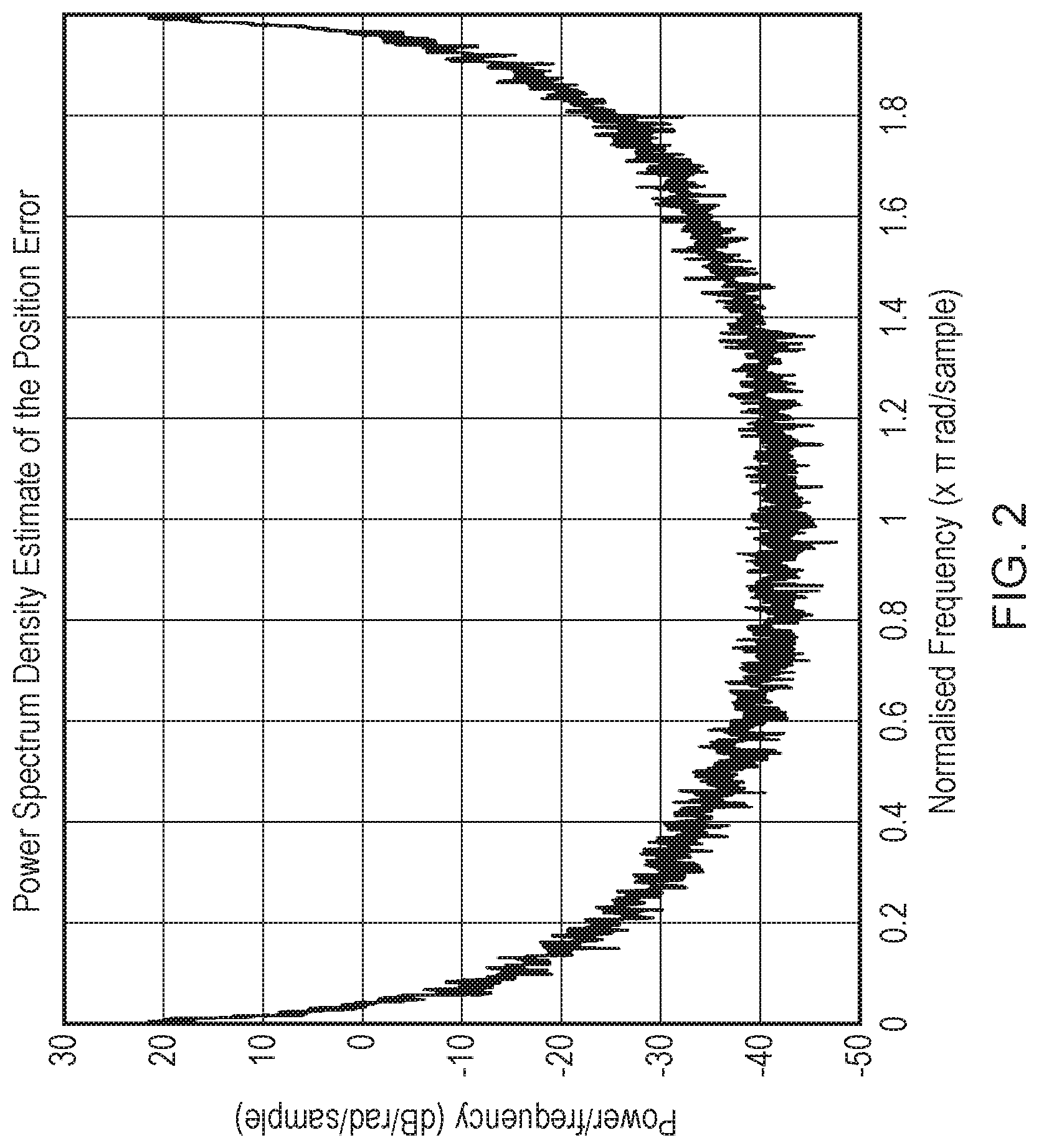
FIG. 2 illustrates a power spectrum density estimate of the position error shown in FIG. 1;
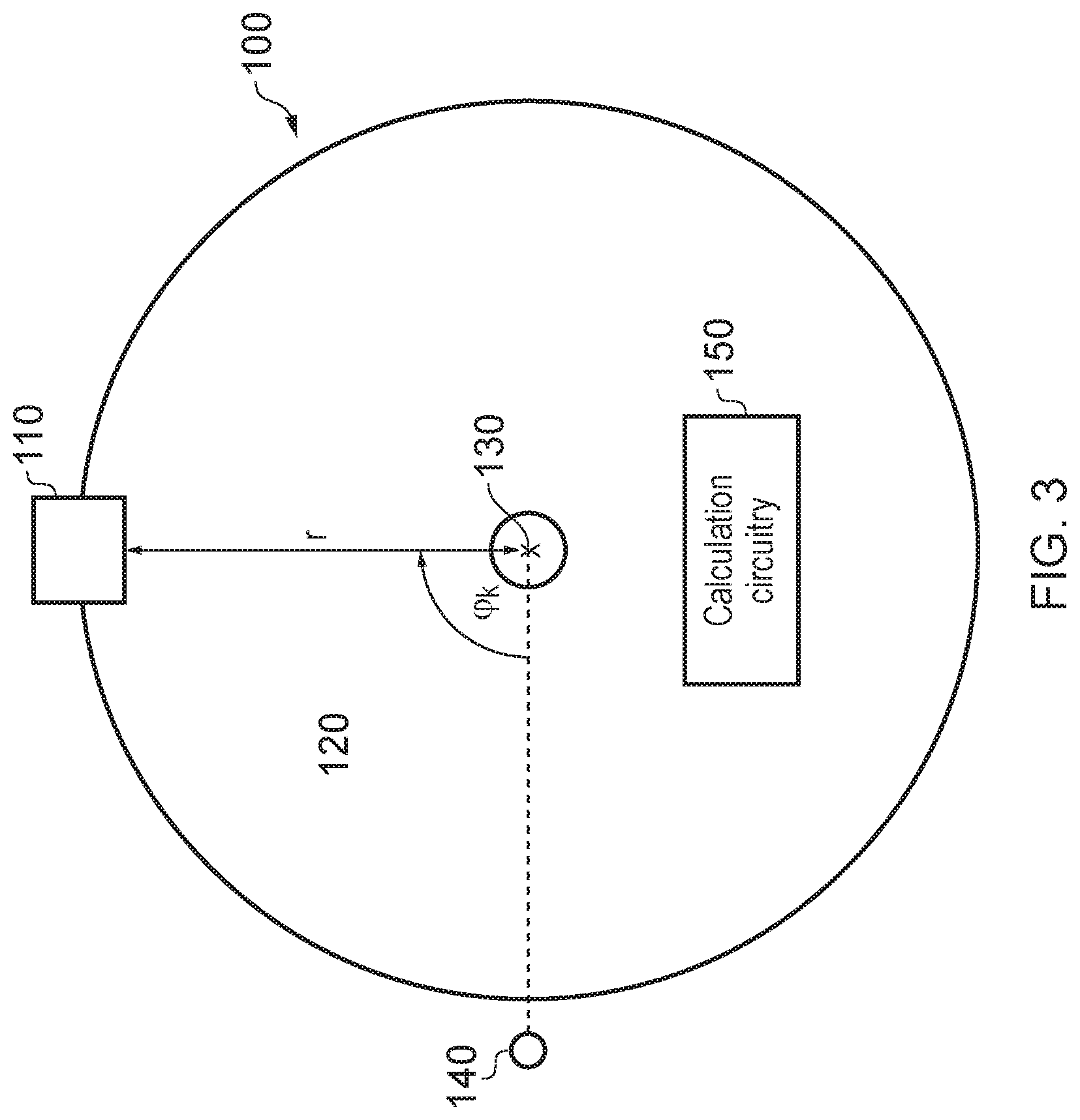
FIG. 3 schematically illustrates an apparatus in accordance with one embodiment;
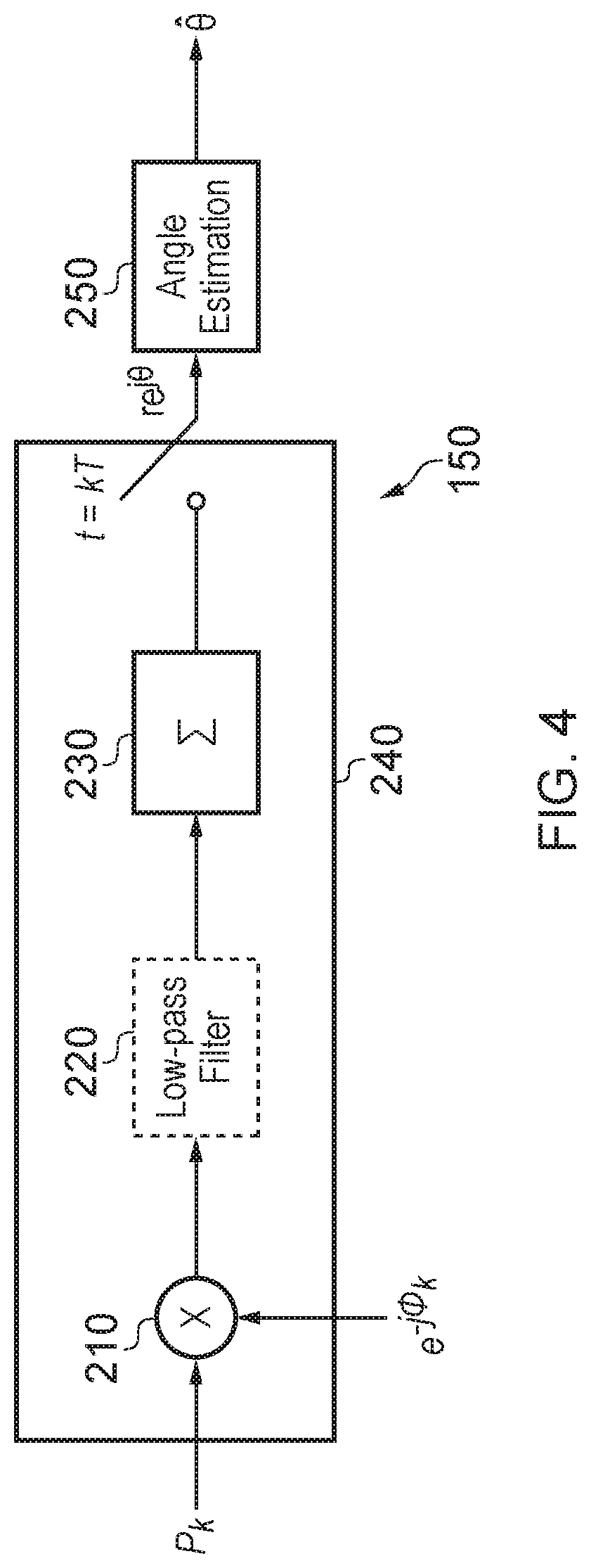
FIG. 4 shows calculation circuitry in accordance with one embodiment;
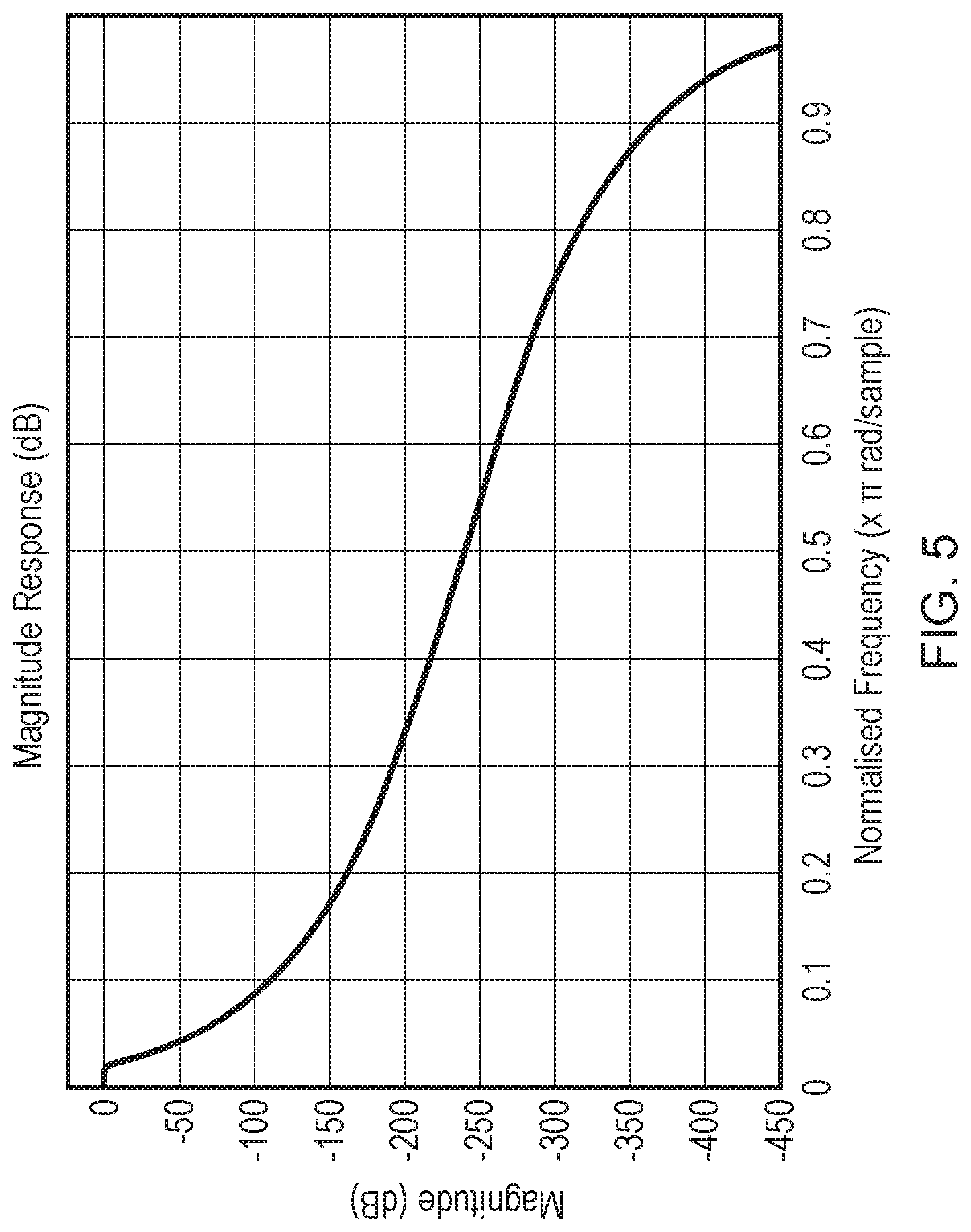
FIG. 5 illustrates characteristics of a suitable low-pass filter for use in one embodiment;
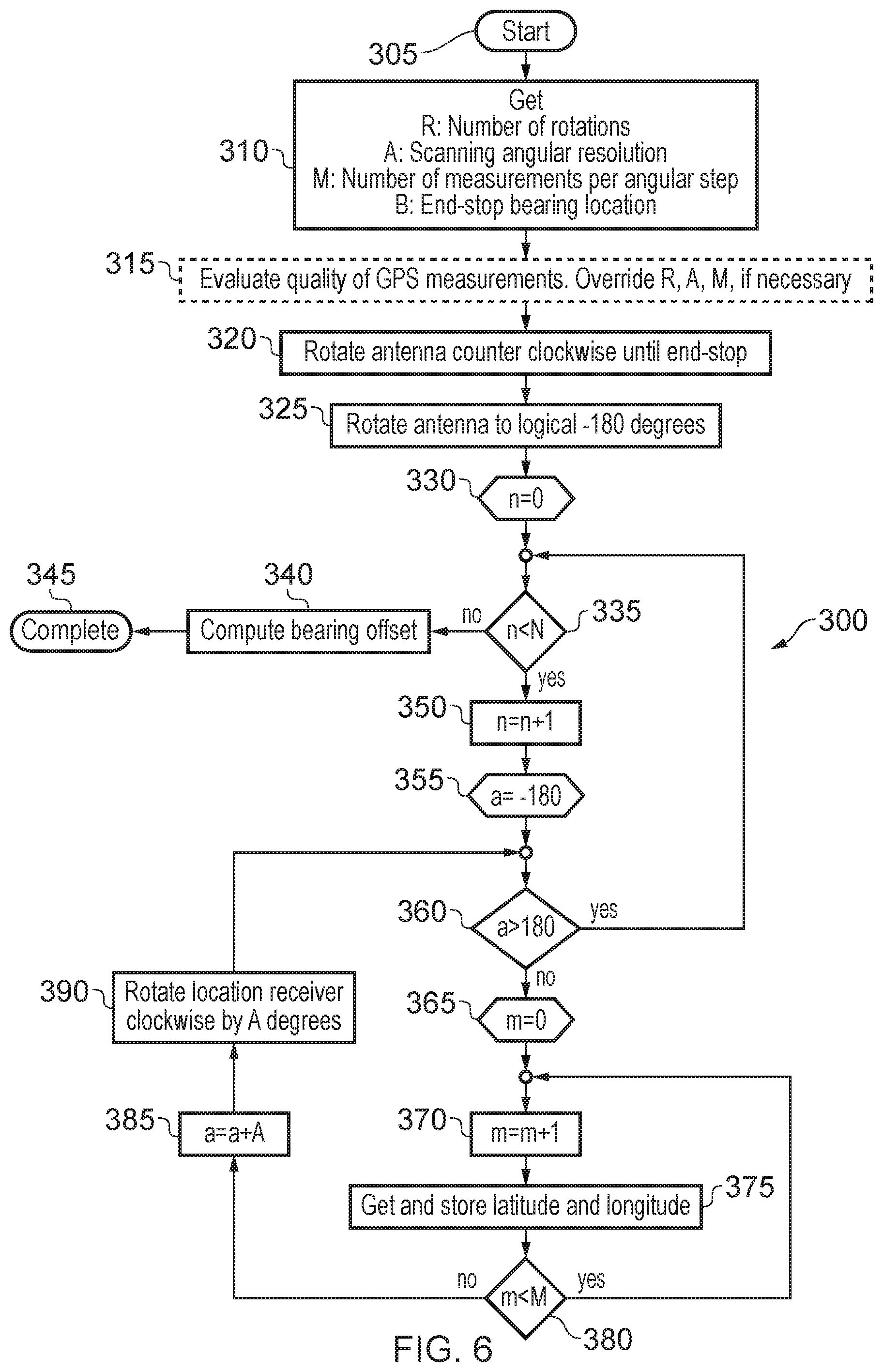
FIG. 6 shows a flow chart illustrating an embodiment of determining a bearing in accordance with one embodiment;
FIG. 7 illustrates a power spectrum density estimate of the position error obtained when using an apparatus in accordance with one embodiment;
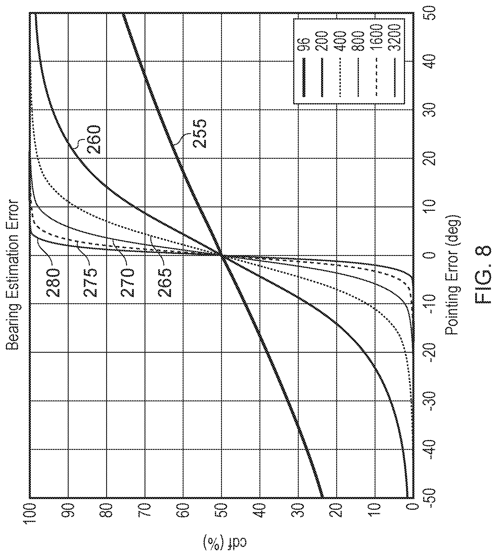
FIG. 8 is a graph showing how the bearing estimation error varies depending on the number of samples taken;
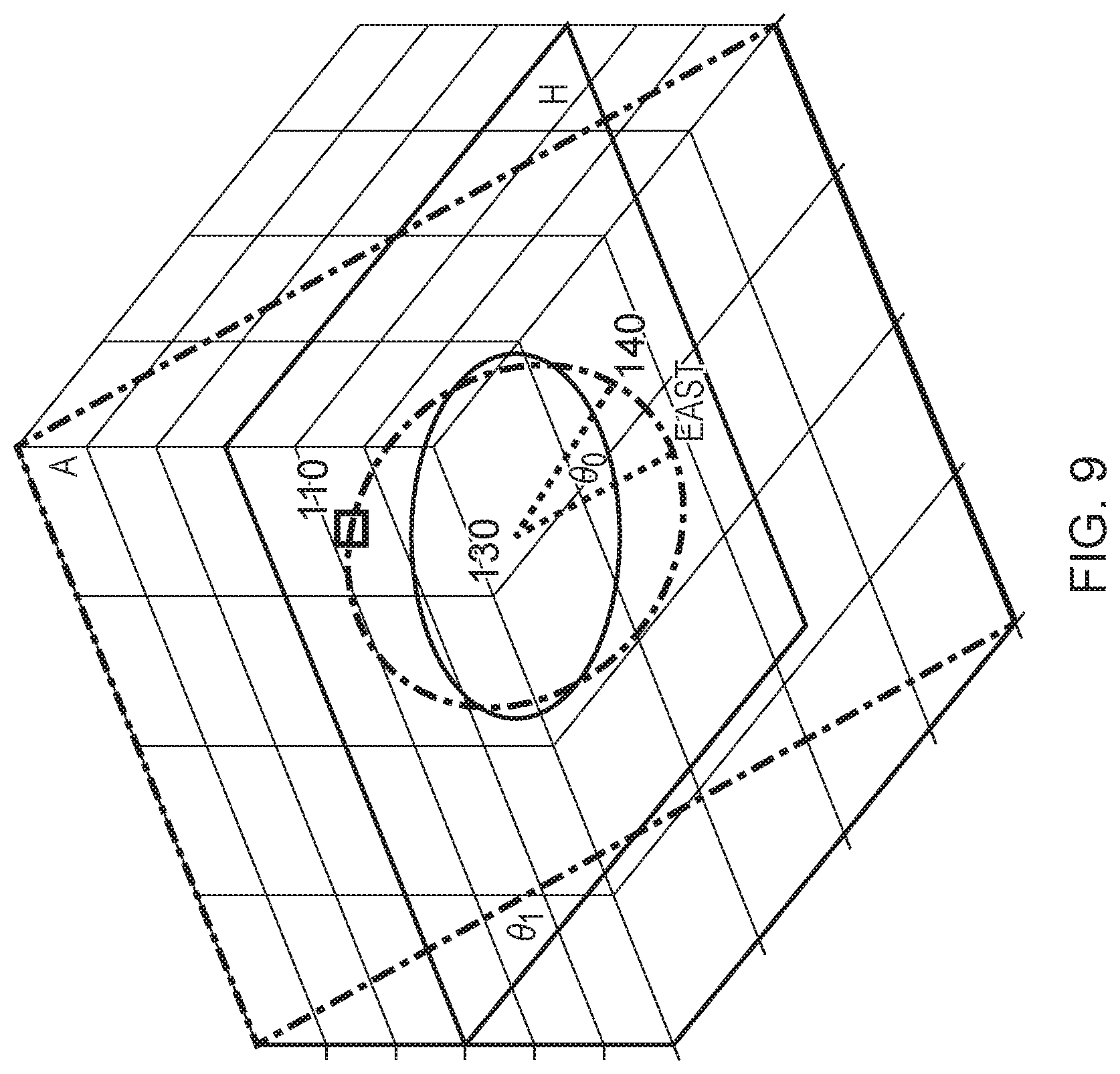
FIG. 9 is an example illustrating the difference between bearing and tilt;
FIG. 10 schematically illustrates calculation circuitry in accordance with one embodiment;
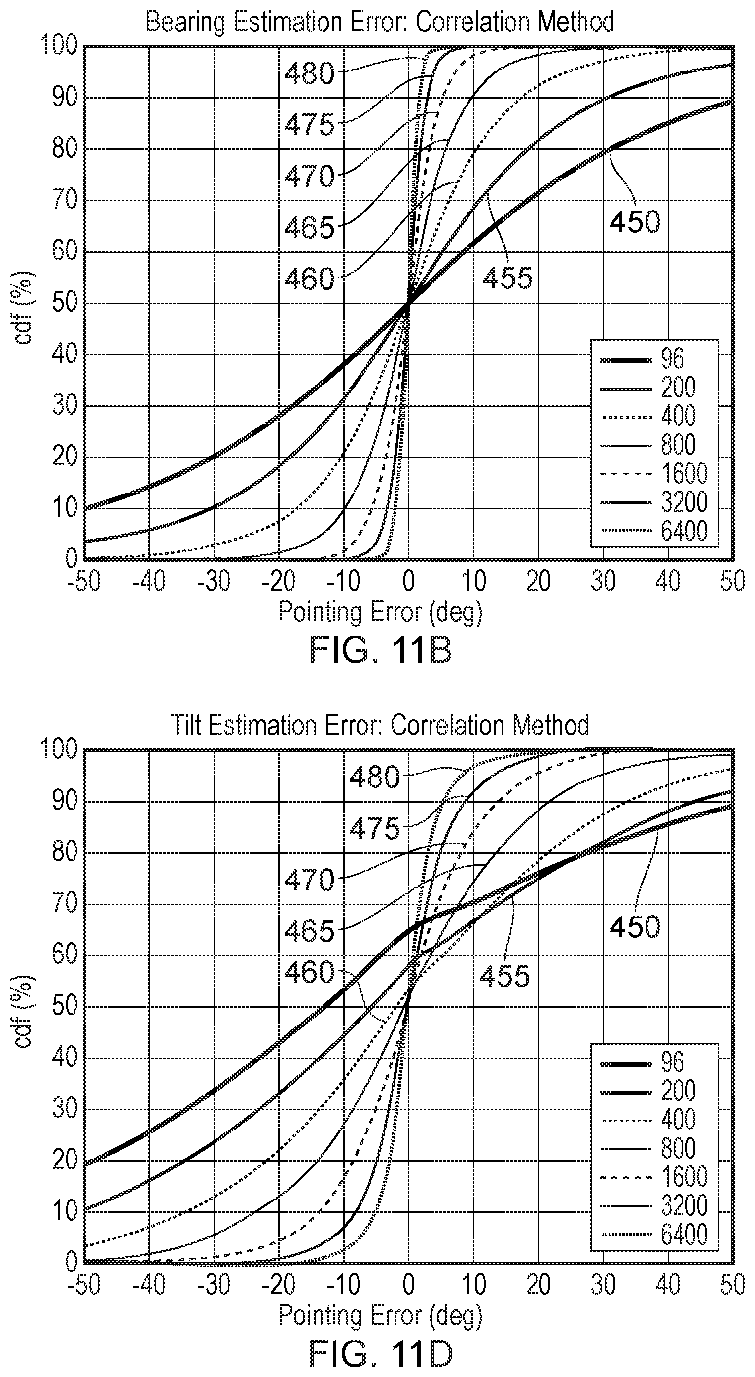
FIGS. 11A, 11B, 11C and 11D are graphs showing how bearing and tilt estimation errors vary depending on the number of samples taken; and
FIG. 12 is a diagram illustrating an example of an apparatus comprising an antenna array in accordance with one embodiment;
Before discussing the embodiments with reference to the accompanying figures, the following description of embodiments and associated advantages is provided.
In accordance with one example configuration there is provided an apparatus comprising: a location receiver to receive a signal indicative of a location of the location receiver; a movement mechanism to rotate the location receiver about an axis and to provide an angle of the location receiver about the axis from a known point; and calculation circuitry to produce an output value indicative of an absolute bearing of the known point about the axis, based on a plurality of given angles of the location receiver about the axis from the known point, and a plurality of associated locations of the location receiver indicated by the signal received when the location receiver is at each of the given angles.
In accordance with the above, a location receiver is rotated (e.g. in a circle) about an axis. At two or more angles (measured in radians) of the location receiver about the axis from the known point (e.g. at two or more angular displacements from the known point), a reading is taken from the location receiver in order to arrive at an angle/reading pair. The calculation circuitry uses two or more of these pairs in order to determine an absolute bearing of the known point. By determining the absolute bearing in this manner, it is possible to compensate for inaccuracy in the location signal while determining the absolute bearing of the known point, which can be used to establish how the apparatus is oriented.
In some embodiments, the apparatus further comprises: a noise filter, wherein the signal indicative of the location of the location receiver comprises a noise component; and the noise filter is to filter out the noise component. The filter may be used to remove a noise component from the received signal that is used to determine a location of the receiver. For example, the filter may be a low-pass filter. The filter can be used to further increase the accuracy of the absolute bearing determined by the calculation circuitry. The noise filter may be implemented at a variety of different points within the apparatus.
Although the calculation circuitry may have a number of different components, in some embodiments, the calculation circuitry comprises: a correlator to correlate the angle of the location receiver about the axis from a known point and output a correlation result; and a phase angle extractor to produce the output value from the correlation result.
In some embodiments, the correlator comprises: a multiplier to multiply the location of the location receiver by e.sup.-j.phi., where j is the unit imaginary number and .phi. is the angle of the location receiver about the axis from the known point with which the location is associated, and to output a plurality of multiplication results; and an integrate and dump filter to operate on the plurality of multiplication results. The correlator in these embodiments considers an angle/reading pair (the reading taken at a particular angle from the known point about the axis). The particular angle is denoted by .phi.. A particular reading is multiplied by the conjugate, i.e. e.sup.-j.phi., where j is the unit imaginary number (often referred to as i, or (-1)). This produces a single multiplication result. By providing multiple angle/reading pairs, a plurality of multiplication results are produced. These are provided to an integrate and dump filter. The integrate and dump filter may, for example, average the provided values and accordingly, eliminate or reduce any noise component inherent in the location value obtained from the location receiver. The result from the integrate and dump filter is the output value and this is indicative of an absolute bearing of the known point about the axis.
The absolute bearing may be represented in a number of different ways. For example, in some embodiments, the absolute bearing of the known point about the axis is a bearing of the known point about the axis relative to true east. The term "true east" is used here to refer to 90 degrees clockwise from true north. For example, true east can be thought of as being along the line of zero latitude. In other embodiments, the absolute bearing may be a bearing relative to true north.
The received signal may be indicative of a location of the location receiver in a number of different ways. For example, in some embodiments, the signal is indicative of a longitude and latitude of the location receiver.
In some embodiments, the signal is a navigation system signal. For example, the signal may be a satellite based global navigation system signal that allows a receiver to estimate or determine its location based on the time taken for signals to travel from one or more satellites to the receiver. These timings may then be used to narrow down the possible locations of the receiver, for example, into an average or expected longitude and latitude. An example of such a satellite based global navigation system signal is a GPS signal. Other systems may include GLONASS (The Russian Global Navigation Satellite System), the planned European Union Galileo positioning system, India's Indian Regional Navigation Satellite System and the Chinese BeiDou Navigation Satellite System.
In some embodiments, the apparatus receives a further signal indicative of a location of the location receiver; and the further signal is a ground based global navigation system signal. Such systems may be used in order to further refine or aid the determination of the location of the location receiver. For example, assisted-GPS (A-GPS) is a ground-based system that can be used to improve the startup performance of a GPS receiver in order for a location receiver to determine its location more quickly.
In some embodiments, the apparatus further comprises: an antenna assembly to perform at least one of receiving or transmitting a further signal, wherein the antenna assembly defines a reference plane; the movement mechanism is to rotate the antenna assembly about the axis; the location receiver is directly or indirectly mounted to the antenna assembly at a distance from the axis equal to the radius such that when the movement mechanism rotates the antenna assembly about the axis, the location receiver rotates about the axis. In such embodiments, the location receiver is directly or indirectly mounted on the antenna assembly such that as the antenna assembly rotates, the location receiver rotates as well. Accordingly, once the absolute bearing of the known point has been determined, since the rotation of the location receiver/antenna assembly around the known point at the axis is known, it is possible to determine the absolute bearing of a reference plane of the antenna assembly. This can be useful where the antenna assembly prominently transmits or receives in a particular direction, in order to help orient the antenna assembly in order to improve reception and/or transmission.
In some embodiments, the apparatus further comprises: an antenna bearing calculation unit to determine an indication of an absolute bearing of the reference plane based on an absolute bearing of the known point about the axis, an angle of the location receiver about the axis from a known point and a position at which the location receiver is directly or indirectly mounted to the antenna assembly. The antenna bearing calculation unit may be used to determine the absolute bearing of the reference plane at a particular time.
There are a number of ways of representing an indication of the absolute bearing of the reference plane. However, in some embodiments, the indication of the absolute bearing of the reference plane is a vector perpendicular to the reference plane.
In some embodiments, the axis is perpendicular to the reference plane; and the axis passes through a mid-point of the antenna assembly. In this manner, the antenna assembly may rotate on the spot. For example, the orientation of the rotation assembly changes without changing the position of the assembly. Conversely, the location receiver continues to rotate at a radius, thereby altering its position as it rotates.
In some embodiments, the axis is upright. For example, the axis may be substantially perpendicular to the plane of the ground.
In some embodiments, the calculation circuitry is to produce the output value and a further output value indicative of a tilt of the location receiver, additionally based on a radius between the location receiver and the axis. The tilt of the location receiver may be defined as, for example, the angle between the horizontal plane (e.g. the plane tangent to the Earth's surface at the location of the apparatus) and the plane formed by the rotation of the location receiver about the axis. Calculating both the tilt and the absolute bearing can be achieved by additionally considering the radius between the location receiver and the axis (in addition to the plurality of given angles of the location receiver about the axis from the known point and the plurality of associated locations of the location receiver indicated by the signal received when the location receiver is at each of the given angles).
There are a number of ways in which the tilt can be determined. In some embodiments, the calculation circuitry comprises cost minimising circuitry to calculate the output value and further output value by performing a cost minimising function. For example, the cost minimising function can be based on a least squares estimate of the output value and the further output value. For example, given a cost function C(absolute bearing, tilt), the cost minimising function may use a least squares estimate in order to seek the absolute bearing and tilt values that best fit the received location data from the location receiver.
In some other embodiments, the calculation circuitry comprises: a correlator to correlate the angle of the location receiver about the axis from a known point and output a correlation result; a phase angle extractor to produce the output value from the correlation result; and a tilt estimator to produce the further output value based on a magnitude of the correlation result.
Particular embodiments will now be described with reference to the figures.
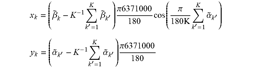
FIG. 1 illustrates the error when a received GPS signal is translated into a longitude and latitude. A GPS receiver was placed in a stationary location. The graph shown in FIG. 1 is a trace that indicates, over time, how the error in calculated position changes. The trace shows that, in this case, the error in the y axis deviated from about 5 metres to -5 metres and the error in the x axis deviated from about -7 metres to just over 15 metres. Hence, it can be seen that the position determined from a GPS signal may be inaccurate. Although this figure relates to the error encountered when using a received GPS signal, it will be appreciated that similar errors may be encountered with other navigation system signals such as satellite based global navigation system signals. Ordinarily, GPS coordinates are given as a longitude ({tilde over (.alpha.)}.sub.k) and latitude ({tilde over (.beta.)}.sub.k) for a reading number k. Small angle approximation can be used to convert longitude and latitude into a Cartesian coordinate system measured in metres where the centre of the Cartesian coordinate system is the average of the longitude and latitude measurements. Specifically, assuming the Earth has a constant radius of 6371000 metres, the x.sub.k and y.sub.k coordinates of a reading number k (out of K total readings) are:
.beta..times.'.times..beta.'.times..pi..times..function..pi..times..times- .'.times..alpha.' ##EQU00001## .alpha.'.times.'.times..alpha.'.times..pi. ##EQU00001.2##
FIG. 2 illustrates a power spectrum density graph of the position error shown in FIG. 1. The profile of the graph shown in FIG. 2 is not flat, thereby indicating that the position error cannot be modelled as Additive White Gaussian Noise. A different process must therefore be used in order to overcome the noise component associated with the location estimation error.
FIG. 3 schematically illustrates an apparatus 100 in accordance with one embodiment. The apparatus comprises a location receiver 110. The location receiver is able to receive a signal that indicates the location of the location receiver 110. In the embodiment shown in FIG. 3, the signal is a GPS signal. However, the signal may be a navigation system signal such as a satellite based global navigation system signal. In some embodiments, the location receiver 110 is able to receive a further signal indicative of the location of the location receiver, from a ground based global navigation system. This can be used to further refine the determined location of the location receiver or may be used to assist in the determination of the location of the location receiver using the signal.
The location receiver 110 may be made to rotate about an axis 130 using a movement mechanism. The location receiver rotates at a radius r from the axis 130. In this embodiment, the location receiver 110 is directly attached to the movement mechanism 120 itself, which rotates about the axis 130. The location receiver 110 is therefore capable of clockwise or anticlockwise movement about axis 130. The location receiver 110 makes an angle with a known point 140 and the movement mechanism 120 is able to determine this angle. In FIG. 3, for example, the location receiver 110 makes a .pi./2 angle with the known point 140 at the axis 130. As the location receiver 110 rotates, it receives a plurality of signals in order to provide a plurality of locations. The calculation circuitry 150 is able to determine the absolute bearing of the known point 140 based on the plurality of locations and the plurality of angles made between the location receiver 110, the axis 130, and the known point 140 when each location was determined. For example, if the location receiver determines a first location L1 at .pi./2 radians and a second location L2 at .pi. radians then these pairings are used by the calculation circuitry 150 in order to determine the absolute bearing of the known point 140. The absolute bearing, in this embodiment, is relative to true east (i.e. 90 degrees clockwise of true north at a latitude of 0). In other embodiments, other points of reference may be used in order to determine the absolute bearing.
Although the above apparatus describes the use of a GPS signal, the location receiver 110 may also use other satellite based systems. For example, the location receiver 110 may operating using a GLONASS (The Russian Global Navigation Satellite System) signal. The apparatus may alternatively use a ground-based navigation signal, or may use such a signal in addition to a satellite based system in order to assist the operation of or refine the estimate produced by, a satellite based system.
FIG. 4 schematically illustrates an example of the calculation circuitry 150 in accordance with one embodiment. The calculation circuitry comprises a correlator 240 and a phase angle extractor 250. The correlator 240 comprises a multiplier 210. The multiplier 210 receives location reading number k, P.sub.k based on the signal received from the location receiver 110. P.sub.k is a complex number, having a real component and an imaginary component with the real component corresponding with an estimate of the location along the x axis and the imaginary component corresponding with an estimate of the location along the y axis. P.sub.k may be thought of as having the following relationship: P.sub.k=re.sup.j(.theta.+.phi..sup.k.sup.)+n.sub.k
Where r is the radius that the location receiver 110 makes with the axis 130, j is the unit imaginary number (i.e. (-1)), .theta. is the absolute bearing of the known point 140 about the axis 130, .phi..sub.k is the bearing of the location receiver 110 from the known point 140 about the axis 130 at reading k, and n.sub.k is the noise component at reading k. This equation represents a conversion of a location reading into polar form. It also recognises that the location of the location receiver about the axis 130 is a function of absolute bearing of the known point 140 and the angle that the location receiver makes with the axis 130 and the known point 140.
The multiplier 210 multiplies P.sub.k by the conjugate e.sup.-j(.phi..sup.k.sup.). This has the effect of cancelling out e.sup.j(.phi..sup.k.sup.): P.sub.k.times.e.sup.-j(.phi..sup.k.sup.)=re.sup.j(.theta.)+n.sub.ke.sup.-- j(.phi..sup.k)
Accordingly, the result of the multiplication is a function of .theta., i.e. the absolute bearing of the known point 140 about the axis 130 and a modified noise component n.sub.ke.sup.-j(.phi..sup.k.sup.).
In this embodiment, the multiplication result passes through a low pass filter 220. This filter is strictly optional and in other embodiments, the multiplication result may pass directly to the integrate and dump filter 230. In this embodiment, the low-pass filter performs a filtering process such that the noise component is reduced.
In any event, the multiplication result or filtered multiplication result passes to the integrate and dump filter 230. This determines a total sum (T) of all readings in order to provide an average value. The averaging performed by the integrate and dump filter 230 has the effect of reducing or eliminating the noise component, thereby producing the value re.sup.j(.theta.). From this, an angle estimation {circumflex over (.theta.)} is produced using a phase angle extractor 250.
In this embodiment, the angle estimate corresponds with the absolute bearing of the known point 140 relative to true east. In other words, an angle estimate of 0 means that the bearing of the known point about the axis 130 points true east (where true east is .pi./2 radians clockwise of true north, along a line of 0 latitude).
FIG. 5 illustrates an example configuration of suitable characteristics for the optional low-pass filter 220. It is clear from FIG. 5 that frequencies in the signal with a low frequency are allowed to pass whereas higher frequency components of the signal are dampened.
FIG. 6 shows a flow chart, which illustrates the procedure for collecting a plurality of location values as the location receiver 110 rotates about the axis 130. A total of N.times.(2.pi./A).times.M readings are taken, in which N is the number of rotations performed by the location receiver 110 about the axis 130, A is the scanning angular resolution (e.g. the number of radians between each angular step), and M is the number of measurements per angular step.
The process starts at step 305 and at step 310, the variables N, A, and M are set to the desired values as specified above. At step 315, the quality of the GPS measurements is evaluated and, if necessary, the values of N, A, and M are changed. For example, if the GPS signal is particularly poor then the values of N, A, and M are altered so that more readings are taken. At step 320, the location receiver is rotated counter clockwise until a mechanical end stop is reached. In other words, the location receiver is rotated counter clockwise as far as it will go. Once this end point is reached, the orientation of the location receiver 110 at this position is assigned an angle. In this embodiment, the assigned angle is -188 degrees because at the position of the mechanical stop, the location receiver 110 will be -188 degrees from the known point about the axis 130. Note that the mechanical stop may be in another position, provided the position is known in advance. At step 325, the antenna is then rotated by 8 degrees until it is at an angle of -180 degrees from the known point. At step 330, the variable n (the current rotation number) is initialised to 0. At step 335, it is determined whether or not n (the current rotation number) is less than N (the number of rotations to be performed). If not, then at step 340, the readings can be used to calculate the bearing offset, and the process completes at step 345. Alternative, if n is not less than N then at step 350, n is incremented by 1. The value a (the current angle of rotation) is initialised to -180 degrees at step 355. At step 360, it is determined whether or not a (the current angle of rotation) is greater than 180 degrees. This represents the situation in which the location receiver has completed an entire rotation from -180 degrees to 180 degrees. If this is the case, then the process returns to step 335. Otherwise, the process proceeds to step 365 where m (the number of readings taken at this position) is initialised to 0. At step 370, m is incremented by one. At step 375, the longitude and latitude are determined from the GPS signal received by the location receiver 110. At step 380, it is determined whether or not m (the number of readings taken at this position) is less than M (the number of readings to take at each position). If so, then the process returns to step 370 where the value of m is incremented and another reading is taken. If not, then the process proceeds to step 385 where the value of a (the current angle of rotation) is incremented by the scanning resolution (A). At step 390, the location receiver 110 is rotated by A degrees and flow proceeds to step 360.
In effect, the flowchart shown in FIG. 6 represents a 3-nested loop. The outer-most loop (steps 330, 335, and 350) iterates through the number of rotations of the location receiver 110. Within each of those iterations, a second loop (steps 355, 360, and 385) iterates through each position at which a reading is to be taken. At each position, an inner-most loop (steps 365, 370, and 380) iterates through the number of readings to be taken at each position. The process therefore collects a set of readings (the number of which is N.times.(2.pi./A).times.M), which is passed through the multiplier 210 and integrate and dump filter 230 as illustrated previously with reference to FIG. 4.
FIG. 7 illustrates a power spectrum density graph for the measurements taken using the process described with reference to FIG. 6 when an angular resolution (A) of 45 degrees is used. As can be seen, a corresponding spectral peak appears at (0.25 .pi. radians/sample), which corresponds with A. This suggests that the use of the correlator 240 that uses a multiplier 210 followed by an integrate and dump filter 230 will yield an accurate estimate of the value of .theta. (i.e. the bearing that the location receiver 110 makes with the known point 140 about the axis 130. Note that if the angular resolution was .pi. radians then the spectral peak would appear at 1.times..pi. radians per sample.
FIG. 8 illustrates a bearing estimation error for 96 readings (255), 200 readings (260), 400 readings (265), 800 readings (270), 1600 readings (275), and 3200 (280) readings. As shown, 90% of the time the bearing estimate is better than .+-.31.6, .+-.14.7, .+-.7.8, .+-.4.4, .+-.2.6 degrees, for 200, 400, 800, 1600, 3200 number of readings, respectively.
Using a similar methodology to that described above, it is possible to determine both the absolute bearing of a known point 140 and also the tilt of the location receiver relative to the plane tangent to the Earth's surface at the location of the location receiver 110. The different angles involved can be seen with reference to FIG. 9. In the figure, H represents the horizontal plane, which is tangent to the Earth's surface at the location of the location receiver 110. In this example, A is a plane made by the rotation of the location receiver 110 around the axis 130. The rotation of the location receiver 110 around the axis 130 is shown by a dotted line. The angle of tilt .theta..sub.1 is the angle between these two planes. Meanwhile, the absolute bearing of the known point 140 about the axis 130 is given by .theta..sub.0. In this example, the absolute bearing is given with reference to true east. The solid circle illustrates the projection of the path taken by the location receiver 110 on to the plane H. This forms an ellipse.
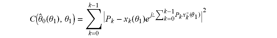
There are a number of ways of determining both .theta..sub.0 and .theta..sub.1. In one embodiment, cost minimising circuitry may be used to perform a cost minimising function based on .theta..sub.0 and .theta..sub.1. For example, consider the following quadratic cost function:
.function..theta..theta..times..function..theta..times..times..times..the- ta. ##EQU00002##
Where k is the number of readings, P.sub.k is location reading number k (as previously discussed), j is the unit imaginary number ( (-1)), .phi..sub.k is the angle made by the location receiver 110 about the axis 130 at reading k and x.sub.k(.theta..sub.1)=r[cos(.phi..sub.k)+j sin(.phi..sub.k)cos(.theta..sub.1)] denotes the trajectory of the ellipse. The aim is to minimise C(.theta..sub.0,.theta..sub.1) with respect to .theta..sub.0 and .theta..sub.1. In other words, this method seeks to compute the absolute bearing and tilt estimates that best fit the received location data.
Minimizing C(.theta..sub.0,.theta..sub.1) with respect to .theta..sub.0 yields:
.theta..function..theta..angle..times..times..times..times..function..the- ta. ##EQU00003##
Where .angle.z denotes the angle of the complex number z and * refers to the complex conjugate. In other words, x.sub.k*(.theta..sub.1)=r[cos(.phi..sub.k)-j sin(.phi..sub.k)cos(.theta..sub.1)]. In the above equation, it can be seen that {circumflex over (.theta.)}.sub.0 is a function of .theta..sub.1. Substituting {circumflex over (.theta.)}.sub.0(.theta..sub.1) into C(.theta..sub.0,.theta..sub.1) yields:
.function..theta..function..theta..theta..times..function..theta..times..- times..times..angle..times..times..times..function..theta. ##EQU00004##
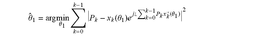
The least squared tilt estimate {circumflex over (.theta.)}.sub.1 is evaluated by firstly finding the minimum of C({circumflex over (.theta.)}.sub.0(.theta..sub.1),.theta..sub.1) and then the least square estimate of the absolute bearing angle {circumflex over (.theta.)}.sub.0 is derived via back substitution. Accordingly, the value of .theta..sub.1 for which C({circumflex over (.theta.)}.sub.0(.theta..sub.1),.theta..sub.1) attains its minimum (arg min) is computed by:
.theta..times..times..theta..times..times..function..theta..times..times.- .times..angle..times..times..times..function..theta. ##EQU00005##
And the least squared estimate of .theta..sub.0 is given by:
.theta..angle..times..times..times..function..theta. ##EQU00006##
Another way to determine both the absolute bearing and tilt is schematically illustrated by the calculation circuitry 400 shown in FIG. 10. In this circuitry, after the accumulate the dump filter 230, the result z is passed to bearing estimation circuitry 250 to determine the absolute bearing as previously discussed, as well as tilt estimation circuitry 420, which is used to determine the tilt. The tilt estimation circuitry determines the tilt based on a function of the magnitude of z. In particular, as previously discussed:
.times..times..times..times..phi. ##EQU00007##
Assuming that .phi..sub.k is sampled uniformly in a circle then by performing trigonometric and algebraic manipulation, it can be shown that:
.times..times..times..theta..function..function..theta. ##EQU00008##
Where n again represents a noise component. The bearing and tilt estimates are therefore given by:
.theta..angle..times..times. ##EQU00009## .theta..function..times..times..times.< ##EQU00009.2##
This method may be less computationally expensive than using the previously described cost minimising circuitry.
FIGS. 11A-11D illustrate the quality of the angle estimates as a function of the number of samples (k) using each of the two methods for determining absolute bearing and tilt. In particular, the figures show the pointing error, in degrees, as a cumulative density function for 96 samples (450), 200 samples (455), 400 samples (460), 800 samples (465), 1600 samples (470), 3200 samples (475), and 6400 samples (480). FIG. 11A illustrates the absolute bearing error when using the least squares (cost minimisation) method. FIG. 11B illustrates the absolute bearing error when using the correlation method (e.g. when using the bearing estimation circuitry and tilt estimation circuitry illustrated in the embodiment of FIG. 10). FIG. 11C illustrates the tilt error when using the least squares (cost minimisation) method and FIG. 11D illustrates the tilt error when using the correlation method (e.g. when using the bearing estimation circuitry and tilt estimation circuitry illustrated in the embodiment of FIG. 10). The figures show that getting absolute bearing and tilt estimates using the computationally simpler correlation method still yields satisfactory results.
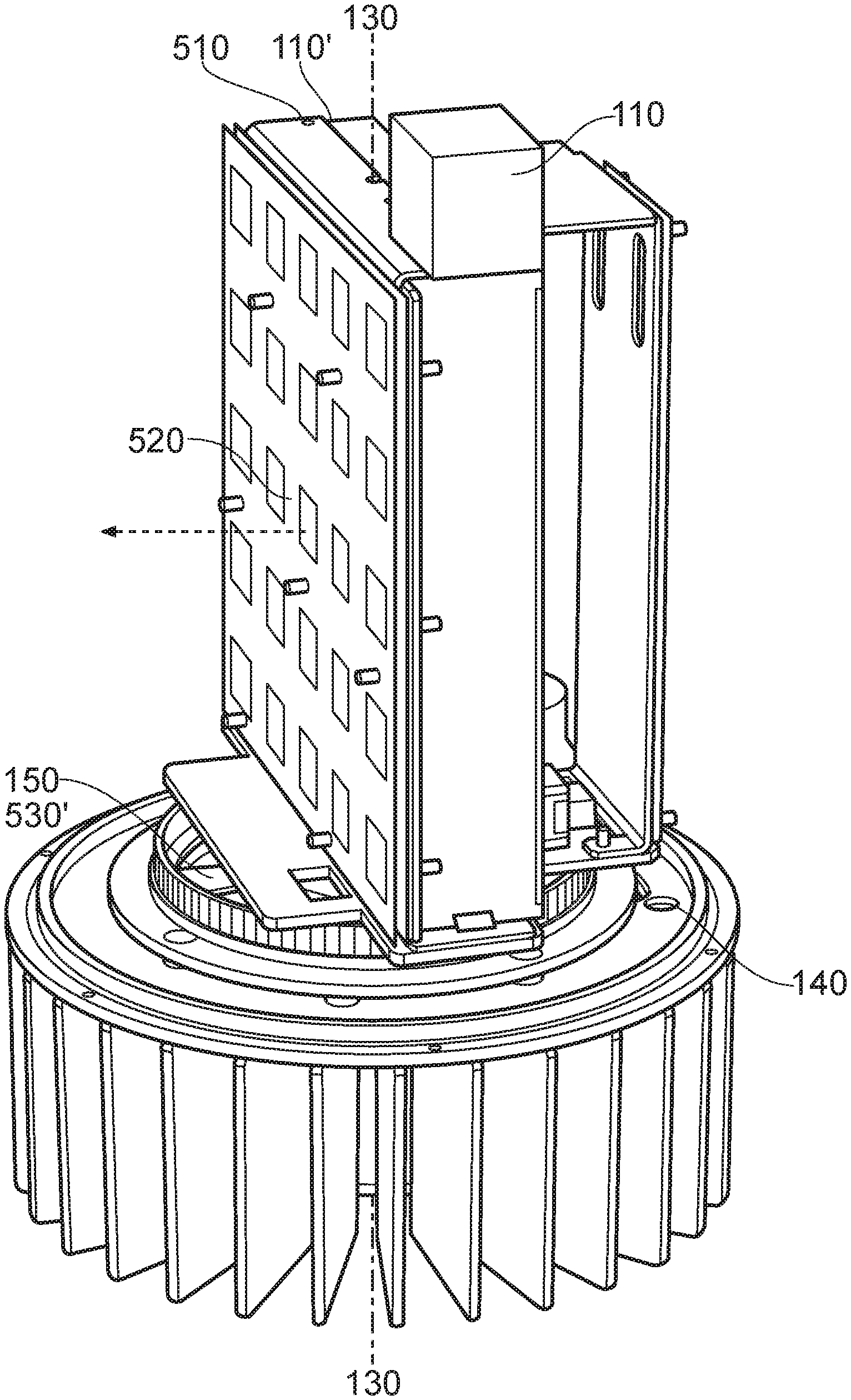
FIG. 12 illustrates an embodiment in which the apparatus 500 additionally comprises an antenna array 510 defining a reference plane 520. The axis 130 is a longitudinal axis of the antenna array 510 and the rotation mechanism 120 rotates the antenna array 510 about this axis. The location receiver 110 is directly attached to the antenna array 520 at a position that is offset from the axis 130 such that rotation of the antenna array 510 about its axis 130 causes the location receiver 110 to rotate about the axis 130 at a radius. Calculation circuitry 150 and an antenna bearing calculation unit 530 are included within the main assembly. The calculation unit 150 determines the absolute bearing and/or tilt of the apparatus 500 as previously discussed. The antenna bearing calculation unit 530 can be used to determine the absolute bearing of the reference plane 520 based on an absolute bearing of the known point 140 about the axis 130, and an angle of the location receiver 110 about the axis 130 from the known point 140 together with knowledge of a position at which the location receiver 110 is directly or indirectly mounted to the antenna assembly 510. For example, if it is known that the known point 140 is 45 degrees clockwise of true east and if it is known that the location receiver 110 is 45 degrees clockwise of the known point 140 then it is known that the location receiver is 90 degrees clockwise of true east. If it is also known that the location receiver is mounted as illustrated in FIG. 12, then it can be known that the direction perpendicular to the reference plane 520 (illustrated by the dashed line in FIG. 12) is 90 degrees clockwise of the angle of the location receiver 110, in other words, that the reference plane faces 180 degrees from true east (i.e. true west). If the location receiver 110 were mounted on the other side of the antenna array 510 at 110' then it would be known that the reference plane 520 faces an angle 90 degrees anti-clockwise of the angle of the location receiver 110. Accordingly, the true bearing of the antenna array 510 can be determined. It will be appreciated that a similar technique may also be used to determine the tilt of the antenna array 510.
In the present application, the words "configured to . . . " are used to mean that an element of an apparatus has a configuration able to carry out the defined operation. In this context, a "configuration" means an arrangement or manner of interconnection of hardware or software. For example, the apparatus may have dedicated hardware which provides the defined operation, or a processor or other processing device may be programmed to perform the function. "Configured to" does not imply that the apparatus element needs to be changed in any way in order to provide the defined operation.
Although illustrative embodiments of the invention have been described in detail herein with reference to the accompanying drawings, it is to be understood that the invention is not limited to those precise embodiments, and that various changes, additions and modifications can be effected therein by one skilled in the art without departing from the scope and spirit of the invention as defined by the appended claims. For example, various combinations of the features of the dependent claims could be made with the features of the independent claims without departing from the scope of the present invention.
* * * * *
D00000
D00001
D00002
D00003
D00004
D00005
D00006
D00007
D00008
D00009
D00010
D00011
D00012
D00013

M00001
M00002

M00003

M00004
M00005
M00006

M00007

M00008

M00009

XML
uspto.report is an independent third-party trademark research tool that is not affiliated, endorsed, or sponsored by the United States Patent and Trademark Office (USPTO) or any other governmental organization. The information provided by uspto.report is based on publicly available data at the time of writing and is intended for informational purposes only.
While we strive to provide accurate and up-to-date information, we do not guarantee the accuracy, completeness, reliability, or suitability of the information displayed on this site. The use of this site is at your own risk. Any reliance you place on such information is therefore strictly at your own risk.
All official trademark data, including owner information, should be verified by visiting the official USPTO website at www.uspto.gov. This site is not intended to replace professional legal advice and should not be used as a substitute for consulting with a legal professional who is knowledgeable about trademark law.