Osteotome with a distal portion for simultaneous advancement and articulation
Purdy , et al.
U.S. patent number 10,660,656 [Application Number 15/862,441] was granted by the patent office on 2020-05-26 for osteotome with a distal portion for simultaneous advancement and articulation. This patent grant is currently assigned to DFine, Inc.. The grantee listed for this patent is DFine, Inc.. Invention is credited to Dan Balbierz, Craig Purdy.


View All Diagrams
| United States Patent | 10,660,656 |
| Purdy , et al. | May 26, 2020 |
Osteotome with a distal portion for simultaneous advancement and articulation
Abstract
Medical devices for creating or expanding a cavity within bone of a patient are disclosed. In some circumstances, a medical device, such as an osteotome is designed to facilitate simultaneous advancement and articulation of a distal portion of the osteotome. Simultaneous advancement and articulation of the distal portion may reduce one or more forces on the distal portion of the osteotome relative to other methods in which advancement and articulation are separated in time, thereby decreasing the risk of breakage or other damage to the osteotome.
| Inventors: | Purdy; Craig (Sunnyvale, CA), Balbierz; Dan (Redwood City, CA) | ||||||||||
|---|---|---|---|---|---|---|---|---|---|---|---|
| Applicant: |
|
||||||||||
| Assignee: | DFine, Inc. (South Jordan,
UT) |
||||||||||
| Family ID: | 62782525 | ||||||||||
| Appl. No.: | 15/862,441 | ||||||||||
| Filed: | January 4, 2018 |
Prior Publication Data
| Document Identifier | Publication Date | |
|---|---|---|
| US 20180193036 A1 | Jul 12, 2018 | |
Related U.S. Patent Documents
| Application Number | Filing Date | Patent Number | Issue Date | ||
|---|---|---|---|---|---|
| 62443371 | Jan 6, 2017 | ||||
| Current U.S. Class: | 1/1 |
| Current CPC Class: | A61B 17/1604 (20130101); A61B 17/1613 (20130101); A61B 17/1671 (20130101); A61B 2017/003 (20130101); A61B 2017/00309 (20130101); A61B 17/3472 (20130101); A61B 17/32 (20130101); A61B 17/320016 (20130101); A61B 2017/00318 (20130101) |
| Current International Class: | A61B 17/16 (20060101); A61B 17/34 (20060101); A61B 17/00 (20060101); A61B 17/32 (20060101) |
References Cited [Referenced By]
U.S. Patent Documents
| 2688329 | September 1954 | Wallace |
| 3140623 | July 1964 | Hoose |
| 3228400 | January 1966 | Armao |
| 3503385 | March 1970 | Stevens |
| 3625200 | December 1971 | Muller |
| 3664344 | May 1972 | Bryne |
| 3692465 | September 1972 | Cohn et al. |
| 3794039 | February 1974 | Kollner et al. |
| 3908637 | September 1975 | Doroshow |
| 4033331 | July 1977 | Guss et al. |
| 4131597 | December 1978 | Bluethgen et al. |
| 4236520 | December 1980 | Anderson |
| 4276880 | July 1981 | Malmin |
| 4294251 | October 1981 | Grennwald et al. |
| 4337773 | July 1982 | Raftopoulos et al. |
| 4386717 | June 1983 | Koob |
| 4399814 | August 1983 | Pratt, Jr. et al. |
| 4411266 | October 1983 | Cosman |
| 4456017 | June 1984 | Miles |
| 4473077 | September 1984 | Noiles |
| 4476861 | October 1984 | Dimakos et al. |
| 4578061 | March 1986 | Lemelson |
| 4586923 | May 1986 | Gould et al. |
| 4595006 | June 1986 | Burke et al. |
| 4619263 | October 1986 | Frisbie et al. |
| 4627434 | December 1986 | Murray |
| 4641654 | February 1987 | Samson et al. |
| 4653489 | March 1987 | Tronzo |
| 4668295 | May 1987 | Bajpai |
| 4719968 | January 1988 | Speros |
| 4722948 | February 1988 | Sanderson |
| 4731054 | March 1988 | Billeter et al. |
| 4742817 | May 1988 | Kawashima et al. |
| 4747840 | May 1988 | Ladika et al. |
| 4748969 | June 1988 | Wardle |
| 4784638 | November 1988 | Ghajar et al. |
| 4795602 | January 1989 | Pretchel et al. |
| 4842603 | June 1989 | Draenert |
| 4843112 | June 1989 | Gerhart et al. |
| 4846814 | July 1989 | Ruiz |
| 4865586 | September 1989 | Hedberg |
| 4869906 | September 1989 | Dingeldein et al. |
| 4888366 | December 1989 | Chu et al. |
| 4900303 | February 1990 | Lemelson |
| 4961730 | October 1990 | Bodicky et al. |
| 4961731 | October 1990 | Bodicky et al. |
| 4963151 | October 1990 | Ducheyene et al. |
| 4969870 | November 1990 | Kramer et al. |
| 4969888 | November 1990 | Scholten et al. |
| 4982730 | January 1991 | Royce |
| 5059193 | January 1991 | Kuslich |
| 4998923 | March 1991 | Samson et al. |
| 5004501 | April 1991 | Faccioli |
| 5017627 | May 1991 | Bonfield |
| 5046513 | September 1991 | O'Leary et al. |
| 5049137 | September 1991 | Thompson |
| 5049157 | September 1991 | Mittelmeier et al. |
| 5085861 | February 1992 | Gerhart et al. |
| 5088991 | February 1992 | Weldon |
| 5116305 | February 1992 | Milder et al. |
| 5092891 | March 1992 | Kummer et al. |
| 5103804 | April 1992 | Abele |
| 5108404 | April 1992 | Scholten et al. |
| 5112303 | May 1992 | Pudenz et al. |
| 5114414 | May 1992 | Buchbinder |
| 5147334 | September 1992 | Moss |
| 5156606 | October 1992 | Chin |
| 5163431 | November 1992 | Greip |
| 5184757 | February 1993 | Giannuzzi |
| 5188619 | February 1993 | Myers |
| 5196201 | March 1993 | Larsson et al. |
| 5197971 | March 1993 | Bonutti |
| 5211631 | May 1993 | Sheaff |
| 5231969 | August 1993 | Middleman et al. |
| 5242082 | September 1993 | Giannuzzi |
| 5264214 | November 1993 | Rhee et al. |
| 5266248 | November 1993 | Ohtsuka et al. |
| 5269750 | December 1993 | Grulke et al. |
| 5282821 | February 1994 | Donahue |
| 5284128 | February 1994 | Hart |
| 5285795 | February 1994 | Ryan et al. |
| 5295980 | March 1994 | Ersek |
| 5296026 | March 1994 | Monroe et al. |
| 5308342 | May 1994 | Sepetka et al. |
| 5322064 | June 1994 | Lundquist |
| 5322505 | June 1994 | Krause et al. |
| 5334181 | August 1994 | Rubinsky et al. |
| 5336699 | August 1994 | Cooke et al. |
| 5343877 | September 1994 | Park |
| 5352715 | October 1994 | Wallace et al. |
| 5356629 | October 1994 | Sander |
| 5360416 | November 1994 | Ausherman et al. |
| 5368598 | November 1994 | Hasson |
| 5372587 | December 1994 | Hammerslag et al. |
| 5378234 | January 1995 | Hammerslag et al. |
| 5380307 | January 1995 | Chee et al. |
| 5385563 | January 1995 | Groos |
| 5389073 | February 1995 | Imran |
| 5425770 | June 1995 | Piez et al. |
| 5431168 | July 1995 | Webster, Jr. |
| 5431639 | July 1995 | Shaw |
| 5437636 | August 1995 | Snoke et al. |
| 5449301 | September 1995 | Hanna et al. |
| 5449351 | September 1995 | Zohmann |
| 5458597 | October 1995 | Edwards et al. |
| 5480382 | January 1996 | Hammerslag et al. |
| 5484424 | January 1996 | Cottenceau et al. |
| 5489275 | February 1996 | Thompson et al. |
| 5496330 | March 1996 | Bates et al. |
| 5512610 | April 1996 | Lin |
| 5514130 | May 1996 | Baker |
| 5514137 | May 1996 | Coutts |
| 5531715 | July 1996 | Engelson et al. |
| 5535922 | July 1996 | Maziarz |
| 5549542 | August 1996 | Kovalcheck |
| 5549679 | August 1996 | Kuslich |
| 5554114 | September 1996 | Wallace et al. |
| 5571085 | November 1996 | Accisano, III |
| 5571088 | November 1996 | Lennox |
| 5574075 | November 1996 | Draemert |
| 5599346 | February 1997 | Edwards et al. |
| 5616121 | April 1997 | McKay |
| 5620447 | April 1997 | Smith et al. |
| 5620467 | April 1997 | Wagner |
| 5624396 | April 1997 | McNamara et al. |
| 5628771 | May 1997 | Mizukawa et al. |
| 5637090 | June 1997 | McGee |
| 5637091 | June 1997 | Hakky et al. |
| 5662680 | September 1997 | Desai |
| 5681269 | October 1997 | Wilcox et al. |
| 5681282 | October 1997 | Eggers et al. |
| 5681317 | October 1997 | Caldarise |
| 5685826 | November 1997 | Bonutti |
| 5695513 | December 1997 | Johnson et al. |
| 5697536 | December 1997 | Eggers et al. |
| 5697909 | December 1997 | Eggers et al. |
| 5700157 | December 1997 | Chung |
| 5704926 | January 1998 | Sutton |
| 5709697 | January 1998 | Ratcliff et al. |
| 5725568 | March 1998 | Hastings |
| 5735829 | April 1998 | Cherian |
| 5741320 | April 1998 | Thornton et al. |
| 5766153 | June 1998 | Eggers et al. |
| 5800408 | September 1998 | Strauss et al. |
| 5810804 | September 1998 | Gough |
| 5810867 | September 1998 | Zarbatany et al. |
| 5820592 | October 1998 | Hammerslag et al. |
| 5833632 | November 1998 | Jacobsen et al. |
| 5833692 | November 1998 | Cesarini et al. |
| 5847046 | December 1998 | Jiang et al. |
| 5849028 | December 1998 | Chen |
| 5851212 | December 1998 | Zirps et al. |
| 5855577 | January 1999 | Murphy-Chutorian et al. |
| 5858003 | January 1999 | Atala |
| 5860952 | January 1999 | Quinn |
| 5860974 | January 1999 | Abele |
| 5876373 | March 1999 | Giba et al. |
| 5891027 | April 1999 | Tu |
| 5902251 | May 1999 | VanHooydonk |
| 5902839 | May 1999 | Lautenschlager et al. |
| 5914356 | June 1999 | Erbe |
| 5921956 | July 1999 | Grinberg et al. |
| 5928239 | July 1999 | Mirza |
| 5931829 | August 1999 | Burbank et al. |
| 5944715 | August 1999 | Goble et al. |
| 5947964 | September 1999 | Eggers |
| 5972015 | October 1999 | Scribner et al. |
| 5997581 | December 1999 | Khalili |
| 6019765 | February 2000 | Thornhill et al. |
| 6027487 | February 2000 | Crocker |
| 6030360 | February 2000 | Biggs |
| 6048346 | April 2000 | Reiley et al. |
| 6059739 | May 2000 | Baumann |
| 6063078 | May 2000 | Wittkampf |
| 6064902 | May 2000 | Haissaguerre |
| 6066154 | May 2000 | Reiley et al. |
| 6066176 | May 2000 | Oshida |
| 6073051 | June 2000 | Sharkey et al. |
| 6080801 | June 2000 | Draenert et al. |
| 6099514 | August 2000 | Sharkey et al. |
| 6106524 | August 2000 | Eggers et al. |
| 6106539 | August 2000 | Fortier |
| 6110155 | August 2000 | Baudino |
| 6123702 | September 2000 | Swanson |
| 6127597 | October 2000 | Beyar et al. |
| 6135999 | October 2000 | Fanton et al. |
| 6146355 | November 2000 | Biggs |
| 6156254 | December 2000 | Andrews et al. |
| 6183435 | February 2001 | Bumbalough et al. |
| 6203507 | March 2001 | Wadsworth et al. |
| 6203574 | March 2001 | Kawamura |
| 6228052 | May 2001 | Pohndorf |
| 6228904 | May 2001 | Yadav et al. |
| 6231569 | May 2001 | Bek et al. |
| 6231615 | May 2001 | Preissman |
| 6235043 | May 2001 | Reiley et al. |
| 6241734 | June 2001 | Scribner et al. |
| 6248110 | June 2001 | Reiley et al. |
| 6251092 | June 2001 | Qin et al. |
| 6258086 | July 2001 | Ashley et al. |
| 6270476 | August 2001 | Santoianni et al. |
| 6280413 | August 2001 | Clark et al. |
| 6280434 | August 2001 | Kinoshita et al. |
| 6280441 | August 2001 | Ryan |
| 6280456 | August 2001 | Scribner et al. |
| 6280473 | August 2001 | Lemperle et al. |
| 6283960 | September 2001 | Ashley |
| 6291547 | September 2001 | Lyles |
| 6312428 | November 2001 | Eggers |
| 6312454 | November 2001 | Stockel et al. |
| 6332894 | December 2001 | Stalcup et al. |
| 6348055 | February 2002 | Preissman |
| 6352533 | March 2002 | Ellman et al. |
| 6358251 | March 2002 | Mirza |
| 6375659 | April 2002 | Erbe et al. |
| 6383188 | May 2002 | Kuslich et al. |
| 6383190 | May 2002 | Preissman |
| 6395007 | May 2002 | Bhatnagar et al. |
| 6408889 | June 2002 | Komachi |
| 6409722 | June 2002 | Hoey et al. |
| 6428894 | August 2002 | Babich et al. |
| 6437019 | August 2002 | Rusin et al. |
| 6440138 | August 2002 | Reiley et al. |
| 6447506 | September 2002 | Swanson et al. |
| 6447514 | September 2002 | Stalcup et al. |
| 6464683 | October 2002 | Samuelson et al. |
| 6478793 | November 2002 | Cosman et al. |
| 6479565 | November 2002 | Stanley |
| 6484904 | November 2002 | Horner et al. |
| 6506217 | January 2003 | Arnett |
| 6511471 | January 2003 | Rosenman et al. |
| 6524296 | February 2003 | Beals |
| 6565588 | May 2003 | Clement et al. |
| 6575969 | June 2003 | Rittman et al. |
| 6575978 | June 2003 | Peterson et al. |
| 6576249 | June 2003 | Gendler et al. |
| 6582446 | June 2003 | Marchosky |
| 6592559 | July 2003 | Pakter et al. |
| 6599961 | July 2003 | Pienkowski et al. |
| 6620162 | July 2003 | Kuslich et al. |
| 6602248 | August 2003 | Sharps et al. |
| 6607544 | August 2003 | Boucher et al. |
| 6613054 | September 2003 | Scribner et al. |
| 6622731 | September 2003 | Daniel et al. |
| 6623448 | September 2003 | Slater |
| 6638268 | October 2003 | Naizi |
| 6641587 | November 2003 | Scribner et al. |
| 6645213 | November 2003 | Sand et al. |
| 6663647 | December 2003 | Reiley et al. |
| 6676665 | January 2004 | Foley et al. |
| 6679886 | January 2004 | Weikel et al. |
| 6689823 | February 2004 | Bellare et al. |
| 6692532 | February 2004 | Healy et al. |
| 6716216 | April 2004 | Boucher et al. |
| 6719761 | April 2004 | Reiley et al. |
| 6719773 | April 2004 | Boucher et al. |
| 6726691 | April 2004 | Osorio et al. |
| 6730095 | May 2004 | Olson, Jr. et al. |
| 6740090 | May 2004 | Cragg et al. |
| 6740093 | May 2004 | Hochschuler et al. |
| 6743239 | June 2004 | Kuehn et al. |
| 6746451 | June 2004 | Middleton et al. |
| 6752863 | June 2004 | Lyles et al. |
| 6753007 | June 2004 | Haggard et al. |
| 6770079 | August 2004 | Bhatnagar et al. |
| 6814734 | November 2004 | Chappuis et al. |
| 6814736 | November 2004 | Reiley et al. |
| 6818001 | November 2004 | Wulfman et al. |
| 6832984 | December 2004 | Stelzer et al. |
| 6835193 | December 2004 | Epstein et al. |
| 6837867 | January 2005 | Kortelling |
| 6863672 | March 2005 | Reiley et al. |
| 6869430 | March 2005 | Balbierz et al. |
| 6869445 | March 2005 | Johnson |
| 6875219 | April 2005 | Arramon |
| 6881214 | April 2005 | Cosman et al. |
| 6887246 | May 2005 | Bhatnagar et al. |
| 6899715 | May 2005 | Beaty |
| 6899719 | May 2005 | Reiley et al. |
| 6907884 | June 2005 | Pellegrino et al. |
| 6913594 | July 2005 | Coleman et al. |
| 6916306 | July 2005 | Jenkins et al. |
| 6923813 | August 2005 | Phillips |
| 6945956 | September 2005 | Waldhauser et al. |
| 6953594 | October 2005 | Lee et al. |
| 6955716 | October 2005 | Xu et al. |
| 6976987 | December 2005 | Flores |
| 6979312 | December 2005 | Shimada |
| 6979352 | December 2005 | Reynolds |
| 6981981 | January 2006 | Reiley et al. |
| 6991616 | January 2006 | Bencini et al. |
| 6998128 | February 2006 | Haggard et al. |
| 7004930 | February 2006 | Marshall |
| 7004945 | March 2006 | Boyd et al. |
| 7008433 | March 2006 | Voellmicke et al. |
| 7018460 | March 2006 | Xu et al. |
| 7022133 | April 2006 | Yee et al. |
| 7029468 | April 2006 | Honebrink |
| 7044954 | May 2006 | Reiley et al. |
| 7059330 | June 2006 | Makower et al. |
| 7063682 | June 2006 | Whayne et al. |
| 7066942 | June 2006 | Treace |
| RE39196 | July 2006 | Ying et al. |
| 7081122 | July 2006 | Reiley et al. |
| 7081161 | July 2006 | Genge et al. |
| 7091258 | August 2006 | Neubert et al. |
| 7091260 | August 2006 | K hn |
| 7094202 | August 2006 | Nobis et al. |
| 7094286 | August 2006 | Liu |
| 7108696 | September 2006 | Daniel et al. |
| 7109254 | September 2006 | Muller et al. |
| 7112205 | September 2006 | Carrison |
| 7114501 | October 2006 | Johnson et al. |
| 7138442 | November 2006 | Smith et al. |
| 7153306 | December 2006 | Ralph et al. |
| 7153307 | December 2006 | Scribner et al. |
| 7156843 | January 2007 | Skarda |
| 7156845 | January 2007 | Mulier |
| 7166121 | January 2007 | Reiley et al. |
| 7172629 | February 2007 | McKay et al. |
| 7179255 | February 2007 | Lettice et al. |
| 7186234 | March 2007 | Dahla et al. |
| 7186761 | March 2007 | Soffiati et al. |
| 7226481 | June 2007 | Kuslich et al. |
| 7252671 | August 2007 | Scribner et al. |
| 7160296 | September 2007 | Pearson et al. |
| 7267683 | September 2007 | Sharkey et al. |
| 7270661 | September 2007 | Dahla et al. |
| 7294127 | November 2007 | Leung |
| 7465318 | December 2008 | Sennett et al. |
| 7480533 | January 2009 | Cosman et al. |
| 7503920 | March 2009 | Siegal |
| 7544196 | June 2009 | Bagga et al. |
| 7559932 | July 2009 | Truckai et al. |
| 7569054 | August 2009 | Michelson |
| 7572263 | August 2009 | Preissman |
| 7591822 | September 2009 | Olson, Jr. et al. |
| 7595634 | September 2009 | Flandre et al. |
| 7625364 | December 2009 | Corcoran et al. |
| 7641664 | January 2010 | Pagano |
| 7731720 | June 2010 | Sand et al. |
| 7811291 | October 2010 | Liu et al. |
| 7824403 | November 2010 | Vaska |
| 7842041 | November 2010 | Liu et al. |
| 7887543 | February 2011 | Sand et al. |
| 7905884 | March 2011 | Simonton et al. |
| 7918874 | April 2011 | Siegal |
| 7972340 | July 2011 | Sand et al. |
| 7976542 | July 2011 | Cosman |
| 8034071 | October 2011 | Scribner et al. |
| 8246627 | August 2012 | Vanleeuwen et al. |
| 8284128 | October 2012 | Kimura |
| 8518036 | August 2013 | Leung |
| 8583260 | November 2013 | Knudson |
| 8591507 | November 2013 | Kramer et al. |
| 8663226 | March 2014 | Germain |
| RE44883 | May 2014 | Cha |
| 8758349 | June 2014 | Germain et al. |
| 8827981 | September 2014 | Liu et al. |
| 8864760 | October 2014 | Kramer et al. |
| 8936631 | January 2015 | Nguyen |
| 9113974 | August 2015 | Germain |
| 9125671 | September 2015 | Germain et al. |
| 9161809 | October 2015 | Germain et al. |
| 9421057 | August 2016 | Germain |
| 9743938 | August 2017 | Germain et al. |
| 2001/0011174 | August 2001 | Reiley et al. |
| 2001/0023349 | September 2001 | Van Tassel et al. |
| 2002/0007180 | January 2002 | Wittenberger et al. |
| 2002/0013600 | January 2002 | Scribner et al. |
| 2002/0026195 | February 2002 | Layne et al. |
| 2002/0026197 | February 2002 | Foley et al. |
| 2002/0068929 | June 2002 | Zvuloni |
| 2002/0068974 | June 2002 | Kuslich et al. |
| 2002/0077595 | June 2002 | Hundertmark et al. |
| 2002/0082605 | June 2002 | Reiley et al. |
| 2002/0115742 | August 2002 | Trieu et al. |
| 2002/0128638 | September 2002 | Chauvel et al. |
| 2002/0133148 | September 2002 | Daniel et al. |
| 2002/0156483 | October 2002 | Voellmicke et al. |
| 2002/0188299 | December 2002 | Reiley et al. |
| 2002/0188300 | December 2002 | Arramon et al. |
| 2003/0014094 | January 2003 | Hammack et al. |
| 2003/0032929 | February 2003 | McGuckin |
| 2003/0036763 | February 2003 | Bhatnagar et al. |
| 2003/0043963 | March 2003 | Yamagami et al. |
| 2003/0050644 | March 2003 | Boucher et al. |
| 2003/0069522 | April 2003 | Jasobsen et al. |
| 2003/0073979 | April 2003 | Naimark et al. |
| 2003/0130664 | July 2003 | Boucher et al. |
| 2003/0163085 | August 2003 | Tanner et al. |
| 2003/0171744 | September 2003 | Leung et al. |
| 2003/0191489 | October 2003 | Reiley et al. |
| 2003/0195547 | October 2003 | Scribner et al. |
| 2003/0212394 | November 2003 | Pearson et al. |
| 2003/0212395 | November 2003 | Woloszko et al. |
| 2003/0220414 | November 2003 | Axen et al. |
| 2003/0225432 | December 2003 | Baptiste et al. |
| 2003/0233096 | December 2003 | Osorio et al. |
| 2004/0023384 | February 2004 | Fukaya |
| 2004/0023784 | February 2004 | Yu et al. |
| 2004/0024081 | February 2004 | Trieu et al. |
| 2004/0024398 | February 2004 | Hovda et al. |
| 2004/0024409 | February 2004 | Sand et al. |
| 2004/0024410 | February 2004 | Olson et al. |
| 2004/0034384 | February 2004 | Fukaya |
| 2004/0044096 | March 2004 | Smith et al. |
| 2004/0044350 | March 2004 | Martin et al. |
| 2004/0059328 | March 2004 | Daniel et al. |
| 2004/0087936 | May 2004 | Stern et al. |
| 2004/0087994 | May 2004 | Suddaby |
| 2004/0092946 | May 2004 | Bagga et al. |
| 2004/0097612 | May 2004 | Rosenberg et al. |
| 2004/0111136 | June 2004 | Sharkey et al. |
| 2004/0127987 | July 2004 | Evans et al. |
| 2004/0133208 | July 2004 | Weikel et al. |
| 2004/0138758 | July 2004 | Evans et al. |
| 2004/0153064 | August 2004 | Foley et al. |
| 2004/0153115 | August 2004 | Reiley et al. |
| 2004/0158237 | August 2004 | Abboud et al. |
| 2004/0167561 | August 2004 | Boucher et al. |
| 2004/0167562 | August 2004 | Osorio et al. |
| 2004/0167625 | August 2004 | Beyar et al. |
| 2004/0210231 | October 2004 | Broucher et al. |
| 2004/0215343 | October 2004 | Hochschuler et al. |
| 2004/0220577 | November 2004 | Cragg |
| 2004/0220680 | November 2004 | Yamamoto et al. |
| 2004/0225296 | November 2004 | Reiss et al. |
| 2004/0226479 | November 2004 | Lyles et al. |
| 2004/0230309 | November 2004 | DiMauro et al. |
| 2004/0236186 | November 2004 | Chu |
| 2004/0247644 | December 2004 | Bratt et al. |
| 2004/0267271 | December 2004 | Scribner et al. |
| 2005/0027245 | February 2005 | Sachdeva et al. |
| 2005/0033303 | February 2005 | Chappuis et al. |
| 2005/0038383 | February 2005 | Kelley et al. |
| 2005/0038422 | February 2005 | Maurice |
| 2005/0043737 | February 2005 | Reiley et al. |
| 2005/0055030 | March 2005 | Falahee |
| 2005/0060030 | March 2005 | Lashinski et al. |
| 2005/0070844 | March 2005 | Chow et al. |
| 2005/0070912 | March 2005 | Voellmicke |
| 2005/0070915 | March 2005 | Mazzuca et al. |
| 2005/0090852 | April 2005 | Layne et al. |
| 2005/0113636 | May 2005 | Lozier et al. |
| 2005/0119650 | June 2005 | Sanders et al. |
| 2005/0124989 | June 2005 | Suddaby |
| 2005/0143827 | June 2005 | Globerman et al. |
| 2005/0177168 | August 2005 | Brunnett et al. |
| 2005/0177210 | August 2005 | Lueng et al. |
| 2005/0182413 | August 2005 | Johnson et al. |
| 2005/0187556 | August 2005 | Stack et al. |
| 2005/0199156 | September 2005 | Khairoun et al. |
| 2005/0209557 | September 2005 | Carroll et al. |
| 2005/0216018 | September 2005 | Sennett |
| 2005/0228391 | October 2005 | Levy et al. |
| 2005/0234425 | October 2005 | Miller et al. |
| 2005/0240193 | October 2005 | Layne et al. |
| 2005/0251266 | November 2005 | Maspero et al. |
| 2005/0251267 | November 2005 | Winterbottom et al. |
| 2005/0261683 | November 2005 | Veldhuizen et al. |
| 2005/0283148 | December 2005 | Janssen |
| 2005/0287771 | December 2005 | Seamons et al. |
| 2006/0024348 | February 2006 | Engqvist et al. |
| 2006/0025763 | February 2006 | Nelson et al. |
| 2006/0041033 | February 2006 | Bisig et al. |
| 2006/0052743 | March 2006 | Reynolds |
| 2006/0064101 | March 2006 | Arramon |
| 2006/0074433 | April 2006 | McGill et al. |
| 2006/0084977 | April 2006 | Lieberman |
| 2006/0085009 | April 2006 | Truckai et al. |
| 2006/0100635 | May 2006 | Reiley et al. |
| 2006/0100706 | May 2006 | Shadduck et al. |
| 2006/0106392 | May 2006 | Embry |
| 2006/0106459 | May 2006 | Truckai et al. |
| 2006/0116689 | June 2006 | Albans et al. |
| 2006/0116690 | June 2006 | Pagano |
| 2006/0122623 | June 2006 | Truckai et al. |
| 2006/0142732 | June 2006 | Karmarkar et al. |
| 2006/0149268 | July 2006 | Truckai et al. |
| 2006/0149281 | July 2006 | Reiley et al. |
| 2006/0156959 | July 2006 | Engqvist et al. |
| 2006/0184106 | August 2006 | McDaniel et al. |
| 2006/0184192 | August 2006 | Markworth et al. |
| 2006/0200121 | September 2006 | Mowery |
| 2006/0206116 | September 2006 | Yeung |
| 2006/0206136 | September 2006 | Sachdeva et al. |
| 2006/0217704 | September 2006 | Cockburn et al. |
| 2006/0217736 | September 2006 | Kaneko |
| 2006/0229625 | October 2006 | Truckai et al. |
| 2006/0229631 | October 2006 | Reiley et al. |
| 2006/0235417 | October 2006 | Sala |
| 2006/0259023 | November 2006 | Abboud et al. |
| 2006/0264819 | November 2006 | Fischer et al. |
| 2006/0264945 | November 2006 | Edidin et al. |
| 2006/0266372 | November 2006 | Miller et al. |
| 2006/0270750 | November 2006 | Almen et al. |
| 2006/0271061 | November 2006 | Beyar et al. |
| 2006/0276797 | December 2006 | Botimer |
| 2006/0276819 | December 2006 | Osorio et al. |
| 2006/0293687 | December 2006 | Bogert |
| 2007/0006692 | January 2007 | Phan |
| 2007/0010845 | January 2007 | Gong et al. |
| 2007/0016130 | January 2007 | Leeflang et al. |
| 2007/0016211 | January 2007 | Botimer |
| 2007/0021769 | January 2007 | Scribner et al. |
| 2007/0043373 | February 2007 | Sala |
| 2007/0055201 | March 2007 | Seto et al. |
| 2007/0055260 | March 2007 | Cragg |
| 2007/0055266 | March 2007 | Osorio et al. |
| 2007/0055275 | March 2007 | Schaller |
| 2007/0055277 | March 2007 | Osorio et al. |
| 2007/0055278 | March 2007 | Osorio et al. |
| 2007/0055279 | March 2007 | Sand et al. |
| 2007/0055281 | March 2007 | Osorio et al. |
| 2007/0055283 | March 2007 | Scribner |
| 2007/0055284 | March 2007 | Osorio |
| 2007/0055285 | March 2007 | Osorio et al. |
| 2007/0055300 | March 2007 | Osorio et al. |
| 2007/0055382 | March 2007 | Osorio et al. |
| 2007/0059281 | March 2007 | Moseley et al. |
| 2007/0067034 | March 2007 | Chirico et al. |
| 2007/0093840 | April 2007 | Pacelli |
| 2007/0114248 | May 2007 | Kovac |
| 2007/0118142 | May 2007 | Krueger et al. |
| 2007/0118143 | May 2007 | Ralph et al. |
| 2007/0142642 | June 2007 | Krueger et al. |
| 2007/0156130 | July 2007 | Thistle |
| 2007/0162042 | July 2007 | Dunker |
| 2007/0173939 | July 2007 | Kim et al. |
| 2007/0185231 | August 2007 | Liu et al. |
| 2007/0197935 | August 2007 | Reiley |
| 2007/0198023 | August 2007 | Sand et al. |
| 2007/0203500 | August 2007 | Gordon |
| 2007/0211563 | September 2007 | DeVries |
| 2007/0233146 | October 2007 | Henniges et al. |
| 2007/0260223 | November 2007 | Scheibe et al. |
| 2007/0260257 | November 2007 | Phan |
| 2007/0270876 | November 2007 | Kuo et al. |
| 2007/0276319 | November 2007 | Betts |
| 2007/0282305 | December 2007 | Goldfarb et al. |
| 2008/0004615 | January 2008 | Woloszko et al. |
| 2008/0033422 | February 2008 | Turner et al. |
| 2008/0058725 | March 2008 | Scribner et al. |
| 2008/0058821 | March 2008 | Maurer et al. |
| 2008/0058827 | March 2008 | Osorio et al. |
| 2008/0058840 | March 2008 | Albrecht |
| 2008/0065020 | March 2008 | Ralph et al. |
| 2008/0065087 | March 2008 | Osorio et al. |
| 2008/0065190 | March 2008 | Osorio et al. |
| 2008/0086142 | April 2008 | Kohm et al. |
| 2008/0140079 | June 2008 | Osorio et al. |
| 2008/0183165 | July 2008 | Buysee et al. |
| 2008/0183265 | July 2008 | Bly |
| 2008/0195112 | August 2008 | Liu et al. |
| 2008/0208255 | August 2008 | Siegal |
| 2008/0221608 | September 2008 | Betts |
| 2008/0228192 | September 2008 | Beyer et al. |
| 2008/0249481 | October 2008 | Crainich |
| 2008/0249525 | October 2008 | Lee et al. |
| 2008/0255571 | October 2008 | Truckai et al. |
| 2008/0269766 | October 2008 | Justis |
| 2008/0269796 | October 2008 | Reiley et al. |
| 2008/0287741 | November 2008 | Ostrovsky et al. |
| 2008/0294167 | November 2008 | Schumacher et al. |
| 2009/0076517 | March 2009 | Reiley et al. |
| 2009/0105775 | April 2009 | Mitchell et al. |
| 2009/0131867 | May 2009 | Liu et al. |
| 2009/0131886 | May 2009 | Liu et al. |
| 2009/0131945 | May 2009 | Liu et al. |
| 2009/0131948 | May 2009 | Liu |
| 2009/0131950 | May 2009 | Liu et al. |
| 2009/0131986 | May 2009 | Lee |
| 2009/0182427 | July 2009 | Liu et al. |
| 2009/0198243 | August 2009 | Melsheimer |
| 2009/0264862 | October 2009 | Neidert et al. |
| 2009/0264892 | October 2009 | Beyar et al. |
| 2009/0292289 | November 2009 | Sand et al. |
| 2009/0293687 | December 2009 | Nino et al. |
| 2009/0299282 | December 2009 | Lau et al. |
| 2010/0057087 | March 2010 | Cha |
| 2010/0082033 | April 2010 | Germain |
| 2010/0114184 | May 2010 | Degtyar |
| 2010/0121332 | May 2010 | Crainich et al. |
| 2010/0152724 | June 2010 | Marion et al. |
| 2010/0160922 | June 2010 | Liu et al. |
| 2010/0211076 | August 2010 | Germain et al. |
| 2010/0274270 | October 2010 | Patel |
| 2010/0298832 | November 2010 | Lau et al. |
| 2011/0034884 | February 2011 | Pellegrino et al. |
| 2011/0098701 | April 2011 | McIntyre et al. |
| 2011/0160737 | June 2011 | Steffen et al. |
| 2011/0251615 | October 2011 | Truckai et al. |
| 2011/0295261 | December 2011 | Germain |
| 2011/0295262 | December 2011 | Germain et al. |
| 2011/0301590 | December 2011 | Podhajsky et al. |
| 2012/0065543 | March 2012 | Ireland |
| 2012/0130381 | May 2012 | Germain |
| 2012/0158004 | June 2012 | Burger et al. |
| 2012/0191095 | July 2012 | Burger et al. |
| 2012/0239049 | September 2012 | Truckai |
| 2012/0265186 | October 2012 | Burger et al. |
| 2012/0277730 | November 2012 | Salahieh |
| 2012/0330180 | December 2012 | Pellegrino et al. |
| 2012/0330301 | December 2012 | Pellegrino et al. |
| 2013/0006232 | January 2013 | Pellegrino |
| 2013/0041377 | February 2013 | Kuntz |
| 2013/0072941 | March 2013 | Tan-Malecki et al. |
| 2013/0231654 | September 2013 | Germain |
| 2013/0237795 | September 2013 | Carr |
| 2013/0261615 | October 2013 | Kramer et al. |
| 2013/0261621 | October 2013 | Kramer et al. |
| 2013/0345709 | December 2013 | Burger et al. |
| 2014/0135779 | May 2014 | Germain |
| 2014/0163566 | June 2014 | Phan et al. |
| 2014/0316413 | October 2014 | Burger et al. |
| 2014/0350542 | November 2014 | Kramer et al. |
| 2014/0371740 | December 2014 | Germain et al. |
| 2015/0216594 | August 2015 | Prakash |
| 2015/0265333 | September 2015 | Shin et al. |
| 2015/0297246 | October 2015 | Patel |
| 2015/0313614 | November 2015 | Germain |
| 2016/0066984 | March 2016 | Janssen et al. |
| 2016/0228131 | August 2016 | Brockman et al. |
| 2017/0095291 | April 2017 | Harrington |
| 2017/0105798 | April 2017 | Allison |
| 2018/0078170 | March 2018 | Panescu et al. |
| 2018/0147006 | May 2018 | Purdy |
| 2018/0147007 | May 2018 | Purdy |
| 2020/0078066 | March 2020 | Purdy et al. |
| 2785207 | Jul 2011 | CA | |||
| 88203061 | Nov 1988 | CN | |||
| 2841051 | Nov 2006 | CN | |||
| 1459691 | Sep 2004 | EP | |||
| 2004242936 | Sep 2004 | JP | |||
| 2008510530 | Apr 2008 | JP | |||
| 2008528081 | Jul 2008 | JP | |||
| 2008541878 | Nov 2008 | JP | |||
| 2010063887 | Mar 2010 | JP | |||
| 2011500156 | Jan 2011 | JP | |||
| 1993004634 | Mar 1993 | WO | |||
| 1996013297 | May 1996 | WO | |||
| 1996020752 | Jul 1996 | WO | |||
| 1997003611 | Feb 1997 | WO | |||
| 2002003870 | Jan 2002 | WO | |||
| 2003101308 | Dec 2003 | WO | |||
| 2005122938 | Dec 2005 | WO | |||
| 2007036815 | Apr 2007 | WO | |||
| 2007087400 | Aug 2007 | WO | |||
| 2008076330 | Jun 2008 | WO | |||
| 2008084479 | Jul 2008 | WO | |||
| 2010039894 | Apr 2010 | WO | |||
| 2010081187 | Jul 2010 | WO | |||
| 2010135602 | Nov 2010 | WO | |||
| 2010135606 | Nov 2010 | WO | |||
| 2011066465 | Jun 2011 | WO | |||
| 2011114602 | Sep 2011 | WO | |||
| 2011137357 | Nov 2011 | WO | |||
| 2011137377 | Nov 2011 | WO | |||
| 2012071464 | May 2012 | WO | |||
| 2013147990 | Oct 2013 | WO | |||
| 2014093673 | Jun 2014 | WO | |||
Other References
|
US 7,063,700 B2, 06/2006, Michelson (withdrawn) cited by applicant . Park, et al., Biomaterials: An Introduction--Second Edition, Plenum Press ,1992 ,177-178. cited by applicant . Park, et al., The Materials Properties of Bone-Particle Impregnated PMMA, Journal of Biomedical Engineering, vol. 108 ,1986 ,141-148. cited by applicant . Office Action dated Dec. 9, 2009 for U.S. Appl. No. 12/262,064. cited by applicant . Office Action dated Dec. 11, 2009 for U.S. Appl. No. 12/261,987. cited by applicant . Disc-O-Tech confidence Cement System at http://www.disc-o-tech.com/Articles/Article.asp?CategoryID=4&ArticleID=16- 8 accessed, ,Dec. 3, 2007. cited by applicant . Dai, et al., Bone-Particle-Impregnated Bone Cement: an in vivo weight-bearing study, Journal Biomedical Materials Search, vol. 25 ,191 ,141-156. cited by applicant . Hasenwinkel, et al.,"A Novel High-Viscosity, Two-Solution Acrylic Bone Cement: Effect of Chemical Composition on Properties", J. Biomed Mater. Res. vol. 47, No. 1 ,1999 ,36-45. cited by applicant . Klawitter, et al., Application of Porous Ceramics for the Attachment of Load Bearing Internal Orthopedic Applications, J. Biomed. Mater. Res. Symp., 2(1) ,1972 ,61-229. cited by applicant . Liu, et al., Bone-Particle-Impregnanted Bone Cement: An In Vitro Study, Journal of Biomedical Materials Research, vol. 21 ,1987 ,247-261. cited by applicant . Office Action dated Dec. 2, 2009 for U.S. Appl. No. 12/029,428. cited by applicant . Office Action dated Nov. 5, 2008 for U.S. Appl. No. 11/941,733. cited by applicant . European Examination Report dated Dec. 19, 2017 for EP13767383.6. cited by applicant . European Search Report dated Jan. 7, 2019 for EP16793433.0. cited by applicant . European Search Report dated Jun. 8, 2017 for EP17154660.9. cited by applicant . International Search Report and Written Opinion dated Jan. 9, 2012 for PCT/US2011/034185. cited by applicant . International Search Report and Written Opinion dated Jan. 22, 2009 for PCT/US2008/83698. cited by applicant . International Search Report and Written Opinion dated Feb. 7, 2018 for PCT/US2017/058303. cited by applicant . International Search Report and Written Opinion dated Feb. 21, 2018 for PCT/US2017/063281. cited by applicant . International Search Report and Written Opinion dated Mar. 30, 2018 for PCT/US2017/065328. cited by applicant . International Search Report and Written Opinion dated Jul. 20, 2010 for PCT/US2010/035687. cited by applicant . International Search Report and Written Opinion dated Jul. 26, 2011 for PCT/US2011/034628. cited by applicant . International Search Report and Written Opinion dated Aug. 25, 2009 for PCT/US2009/035726. cited by applicant . Notice of Allowance dated Jan. 4, 2017 for U.S. Appl. No. 13/302,927. cited by applicant . Notice of Allowance dated Feb. 21, 2019 for U.S. Appl. No. 14/139,372. cited by applicant . Notice of Allowance dated Apr. 3, 2019 for U.S. Appl. No. 15/349,715. cited by applicant . Notice of Allowance dated May 3, 2017 for U.S. Appl. No. 14/815,620. cited by applicant . Notice of Allowance dated May 11, 2018 for U.S. Appl. No. 14/453,427. cited by applicant . Notice of Allowance dated May 26, 2015 for U.S. Appl. No. 13/098,116. cited by applicant . Notice of Allowance dated Nov. 9, 2017 for U.S. Appl. No. 14/815,812. cited by applicant . Office Action dated Jan. 18, 2017 for U.S. Appl. No. 14/815,620. cited by applicant . Office Action dated Jan. 26, 2011 for U.S. Appl. No. 11/941,764. cited by applicant . Office Action dated Jan. 26, 2017 for U.S. Appl. No. 14/815,812. cited by applicant . Office Action dated Feb. 23, 2010 for U.S. Appl. No. 11/941,733. cited by applicant . Office Action dated Feb. 23, 2010 for U.S. Appl. No. 11/941,764. cited by applicant . Office Action dated dated Mar. 21, 2011 for U.S. Appl. No. 11/941,764. cited by applicant . Office Action dated Mar. 21, 2011 for U.S. Appl. No. 12/029,428. cited by applicant . Office Action dated Apr. 24, 2017 for U.S. Appl. No. 14/453,427. cited by applicant . Office Action dated Apr. 26, 2010 for U.S. Appl. No. 12/029,428. cited by applicant . Office Action dated May 1, 2009 for U.S. Appl. No. 12/261,987. cited by applicant . Office Action dated May 5, 2010 for U.S. Appl. No. 11/941,764. cited by applicant . Office Action dated May 6, 2019 for U.S. Appl. No. 15/675,315. cited by applicant . Office Action dated May 13, 2009 for U.S. Appl. No. 12/029,428. cited by applicant . Office Action dated May 17, 2010 for U.S. Appl. No. 12/261,987. cited by applicant . Office Action dated May 21, 2014 for U.S. Appl. No. 13/098,116. cited by applicant . Office Action dated May 31, 2016 for U.S. Appl. No. 14/815,620. cited by applicant . Office Action dated Jun. 8, 2009 for U.S. Appl. No. 11/941,764. cited by applicant . Office Action dated Jun. 12, 2009 for U.S. Appl. No. 11/941,733. cited by applicant . Office Action dated Jun. 21, 2013 for U.S. Appl. No. 13/215,098. cited by applicant . Office Action dated Jul. 11, 2017 for U.S. Appl. No. 14/815,812. cited by applicant . Office Action dated Jul. 12, 2010 for U.S. Appl. No. 11/941,764. cited by applicant . Office Action dated Jul. 25, 2011 for U.S. Appl. No. 11/941,733. cited by applicant . Office Action dated Jul. 29, 2013 for U.S. Appl. No. 13/098,116. cited by applicant . Office Action dated Sep. 1, 2010 for U.S. Appl. No. 12/029,428. cited by applicant . Office Action dated Oct. 2, 2018 for U.S. Appl. No. 14/139,372. cited by applicant . Office Action dated Oct. 30, 2018 for U.S. Appl. No. 15/349,715. cited by applicant . Office Action dated Nov. 3, 2008 for U.S. Appl. No. 11/941,764. cited by applicant . Office Action dated Nov. 3, 2008 for U.S. Appl. No. 12/029,428. cited by applicant . Notice of Allowance dated Dec. 13, 2018 for U.S. Appl. No. 15/917,454. cited by applicant . European Search Report dated Nov. 15, 2017 for EP09818476.5. cited by applicant . Search Report dated Nov. 16, 2016 for EP14772615.2. cited by applicant . International Search Report and Written Opinion dated Nov. 20, 2009 for PCT/US2009/059113. cited by applicant . Allowance dated Jan. 18, 2017 for U.S. Appl. No. 13/097,998. cited by applicant . Allowance dated Apr. 9, 2014 for U.S. Appl. No. 12/578,455. cited by applicant . Allowance dated Apr. 23, 2018 for U.S. Appl. No. 13/083,411. cited by applicant . Allowance dated Aug. 24, 2018 for U.S. Appl. No. 15/388,598. cited by applicant . Allowance dated Oct. 28, 2016 for U.S. Appl. No. 13/853,397. cited by applicant . Allowance dated Nov. 8, 2013 for U.S. Appl. No. 12/578,455. cited by applicant . Allowance dated Nov. 18, 2016 for U.S. Appl. No. 13/097,998. cited by applicant . Allowance dated Nov. 25, 2013 for U.S. Appl. No. 12/571,174. cited by applicant . Allowance dated Nov. 25, 2016 for U.S. Appl. No. 13/853,397. cited by applicant . Notice of Allowance dated Dec. 28, 2017 for U.S. Appl. No. 15/211,359. cited by applicant . Notice of Allowance dated Aug. 31, 2016 for U.S. Appl. No. 14/887,007. cited by applicant . Office Action dated Feb. 3, 2016 for U.S. Appl. No. 13/853,397. cited by applicant . Office Action dated Feb. 10, 2015 for U.S. Appl. No. 13/083,411. cited by applicant . Office Action dated Mar. 1, 2017 for U.S. Appl. No. 15/211,359. cited by applicant . Office Action dated Apr. 19, 2018 for U.S. Appl. No. 15/388,598. cited by applicant . Office Action dated May 24, 2012 for U.S. Appl. No. 12/578,455. cited by applicant . Office Action dated Jun. 4, 2018 for U.S. Appl. No. 15/349,715. cited by applicant . Office Action dated Jun. 22, 2018 for U.S. Appl. No. 15/917,454. cited by applicant . Office Action dated Jun. 25, 2015 for U.S. Appl. No. 13/853,397. cited by applicant . Office Action dated Jun. 29, 2018 for U.S. Appl. No. 15/449,591. cited by applicant . Office Action dated Jul. 12, 2017 for U.S. Appl. No. 13/083,411. cited by applicant . Office Action dated Jul. 30, 2013 for U.S. Appl. No. 13/083,411. cited by applicant . Office Action dated Sep. 6, 2017 for U.S. Appl. No. 15/211,359. cited by applicant . Office Action dated Sep. 26, 2017 for U.S. Appl. No. 15/388,598. cited by applicant . Office Action dated Nov. 12, 2013 for U.S. Appl. No. 13/083,411. cited by applicant . Office Action dated Nov. 25, 2016 for U.S. Appl. No. 13/083,411. cited by applicant . Office Action dated Dec. 3, 2012 for U.S. Appl. No. 12/571,174. cited by applicant . Office Action dated Feb. 27, 2013 for U.S. Appl. No. 12/578,455. cited by applicant . Office Action dated Jul. 12, 2016 for U.S. Appl. No. 14/887,007. cited by applicant . Office Action dated Sep. 10, 2013 for U.S. Appl. No. 12/571,174. cited by applicant . Notice of Allowance dated Aug. 8, 2019 for U.S. Appl. No. 15/836,125. cited by applicant . Notice of Allowance dated Aug. 9, 2019 for U.S. Appl. No. 15/836,241. cited by applicant . International Search Report and Written Opinion dated Apr. 23, 2016 for PCT/US2018/012372. cited by applicant . Office Action dated Dec. 26, 2019 for U.S. Appl. No. 15/822,864. cited by applicant . Notice of Allowance dated Sep. 20, 2019 for U.S. Appl. No. 15/793,509. cited by applicant . Office Action dated Nov. 7, 2019 for U.S. Appl. No. 15/675,315. cited by applicant . Notice of Allowance dated Feb. 19, 2020 for U.S. Appl. No. 15/675,315. cited by applicant . International Search Report and Written Opinion dated Apr. 8, 2020 for PCT/US2019060279. cited by applicant. |
Primary Examiner: Beccia; Christopher J
Attorney, Agent or Firm: Stoel Rives LLP
Parent Case Text
RELATED APPLICATIONS
This application claims priority to U.S. Provisional Application No. 62/443,371, filed on Jan. 6, 2017 and titled, "Osteotome with a Distal Portion For Simultaneous Advancement and Articulation," which is hereby incorporated by reference in its entirety.
Claims
We claim:
1. A medical device for creating or expanding a cavity within bone of a patient, the medical device comprising: a housing; a first shaft that is threadably coupled to the housing; a second shaft that is threadably coupled to the first shaft; a third shaft that is coupled to the first shaft such that a proximal portion of the third shaft moves axially with the first shaft; and a fourth shaft that is coupled to the second shaft such that a proximal portion of the fourth shaft moves axially with the second shaft; wherein the medical device is configured such that rotation of the first shaft relative to the housing in a first direction results in simultaneous displacement of a distal tip of the medical device in a distal direction relative to the housing and displacement of the distal tip of the medical device in a direction that is lateral to a longitudinal axis of the medical device, and wherein the medical device is configured such that rotation of the first shaft relative to the housing results in (1) axial displacement of the first shaft and the proximal portion of the third shaft relative to the housing at a first rate and (2) axial displacement of the second shaft and the fourth shaft relative to the housing at a second rate that is different from the first rate.
2. The medical device of claim 1, wherein the second shaft is coupled to the housing to prevent rotation of the second shaft relative to the housing.
3. The medical device of claim 1, wherein: the first shaft comprises exterior threads that threadably engage threads of the housing; and the second shaft comprises exterior threads that threadably engage with interior threads of the first shaft; wherein the exterior threads of the first shaft have a pitch that is greater than a pitch of the exterior threads of the second shaft.
4. The medical device of claim 3, wherein: the exterior threads of the first shaft form a right-handed helix; and the exterior threads of the second shaft form a right-handed helix.
5. The medical device of claim 1, wherein the fourth shaft is at least partially disposed within an elongate lumen of the third shaft.
6. The medical device of claim 1, further comprising a handle that is coupled to the first shaft such that rotation of the handle results in rotation of the first shaft.
7. The medical device of claim 1, further comprising: a casing that is fixedly coupled to the second shaft and a proximal end of the third shaft; and a shuttle that is rotatably, but not threadably, coupled to the first shaft, wherein the shuttle is disposed within the housing; wherein rotation of the first shaft with respect to the housing results in axial displacement of the casing relative to the shuttle.
8. The medical device of claim 7, wherein the housing comprises one or more recesses that interact with the casing to prevent rotation of the second shaft relative to the housing.
9. The medical device of claim 1, wherein the housing comprises an adaptor that is configured to facilitate attachment of the housing to an introducer.
10. The medical device of claim 1, wherein: a proximal portion of the fourth shaft is longitudinally displaceable relative to the third shaft; and the fourth shaft is attached to the third shaft at a position that is adjacent a distal end of the third shaft.
11. An osteotome comprising: a housing; a first shaft that is threadably coupled to the housing; a second shaft that is threadably coupled to the first shaft; a third shaft that is coupled to the first shaft such that axial displacement of the first shaft a first distance relative to the housing results in axial displacement of the third shaft a distance relative to the housing that is equal to the first distance; a fourth shaft that is at least partially disposed within an elongate lumen of the third shaft, wherein the fourth shaft is coupled to the second shaft such that axial displacement of the second shaft a second distance relative to the housing results in axial displacement of the fourth shaft a distance relative to the housing that is equal to the second distance; and a distal portion of the osteotome, the distal portion comprising both a portion of the third shaft and a portion of the fourth shaft; wherein rotation of the first shaft relative to the housing simultaneously causes (1) axial displacement of the first shaft relative to the housing at a first rate, (2) axial displacement of the second shaft relative to the housing at a second rate that is different from the first rate, and (3) articulation of the distal portion such that a distal tip of the osteotome is laterally displaced relative to a longitudinal axis of the osteotome.
12. The osteotome of claim 11, wherein rotation of the first shaft relative to the housing causes displacement of the distal portion in an axial direction relative to the housing.
13. The osteotome of claim 11, wherein: the first shaft comprises exterior threads that threadably engage with interior threads of the housing; and the second shaft comprises exterior threads that threadably engage with interior threads of the first shaft; wherein the exterior threads of the first shaft have a pitch that is greater than a pitch of the exterior threads of the second shaft.
14. A method of manipulating an osteotome, the method comprising: obtaining the osteotome of claim 11; inserting a distal portion of the osteotome into bone of a patient; and rotating the first shaft of the osteotome relative to the housing.
15. The method of claim 14, wherein inserting the distal portion of the osteotome into bone of the patient comprises inserting the distal portion of the osteotome through an introducer.
16. The method of claim 15, further comprising coupling the housing to the introducer prior to rotating the first shaft of the osteotome relative to the housing.
17. The method of claim 14, wherein the bone of the patient is a human vertebra.
Description
TECHNICAL FIELD
The present disclosure relates generally to the field of medical devices. More particularly, some embodiments relate to osteotomes that are configured for simultaneous advancement and articulation of a distal portion of the osteotome. Related methods and systems are also disclosed.
BRIEF DESCRIPTION OF THE DRAWINGS
The written disclosure herein describes illustrative embodiments that are non-limiting and non-exhaustive. Reference is made to certain of such illustrative embodiments that are depicted in the figures, in which:
FIG. 1 is a perspective view of an osteotome.
FIG. 2 is an alternative perspective view of the osteotome of FIG. 1.
FIG. 3 is a cross-sectional view of the osteotome of FIG. 1 through plane 3-3 of FIG. 1.
FIG. 4 is a cross-sectional perspective view of the osteotome of FIG. 1 through plane 4-4 of FIG. 1.
FIG. 5 is an exploded perspective view of the osteotome of FIG. 1.
FIG. 6 is a perspective view of a distal portion of the osteotome of FIG. 1 in a fully retracted and straight configuration.
FIG. 7 is a bottom view of the distal portion of the osteotome of FIG. 1 in a fully retracted and straight configuration.
FIG. 8 is a cross-sectional side view of the distal portion of the osteotome of FIG. 1 in a fully retracted and straight configuration.
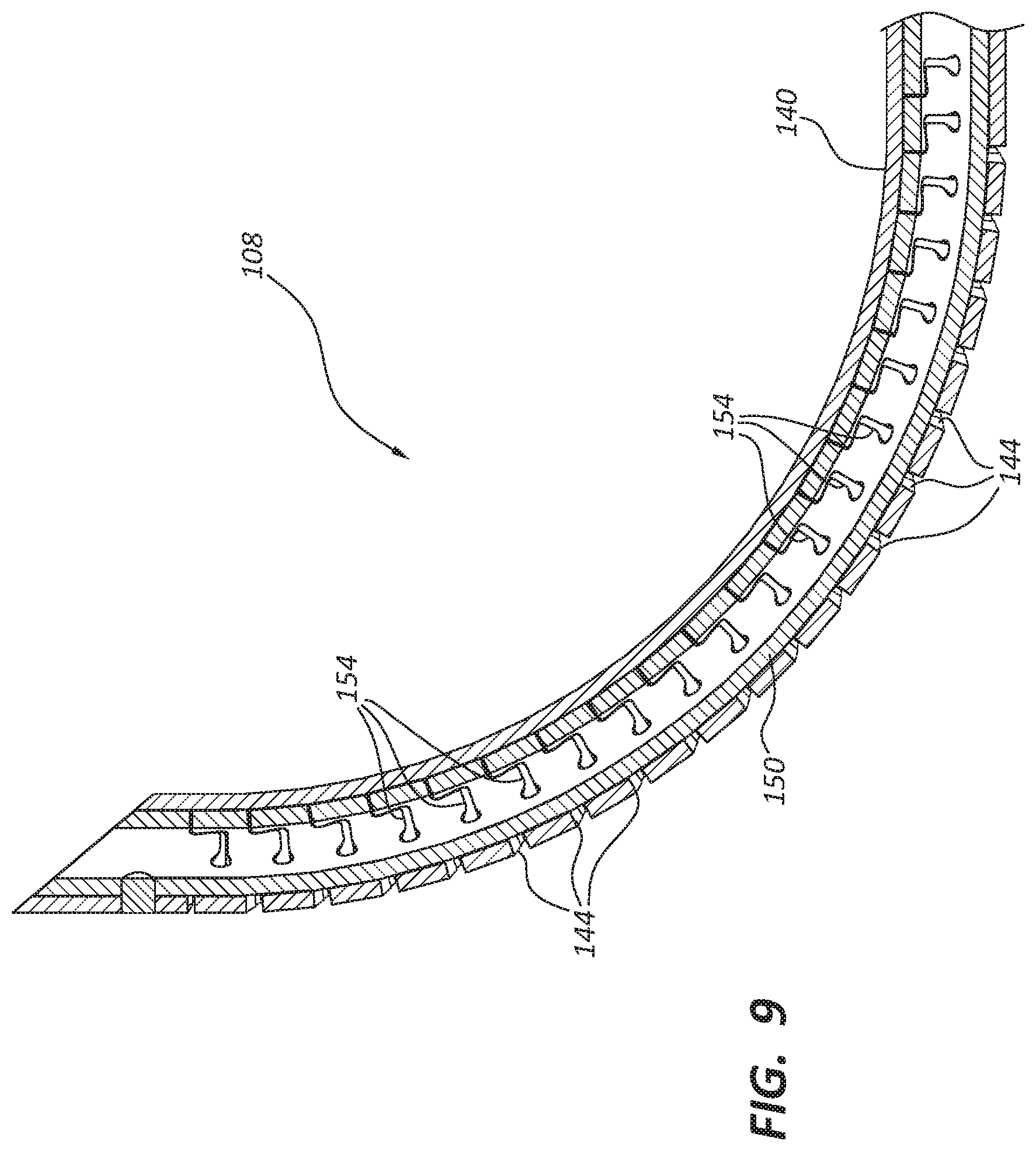
FIG. 9 is a cross-sectional side view of a distal portion of the osteotome of FIG. 1 in a fully advanced and articulated configuration.
FIG. 10A is a cross-sectional view of the osteotome of FIG. 1 in a first configuration.
FIG. 10B depicts the osteotome of FIG. 1 in a vertebra of the patient when the osteotome is in the first configuration.
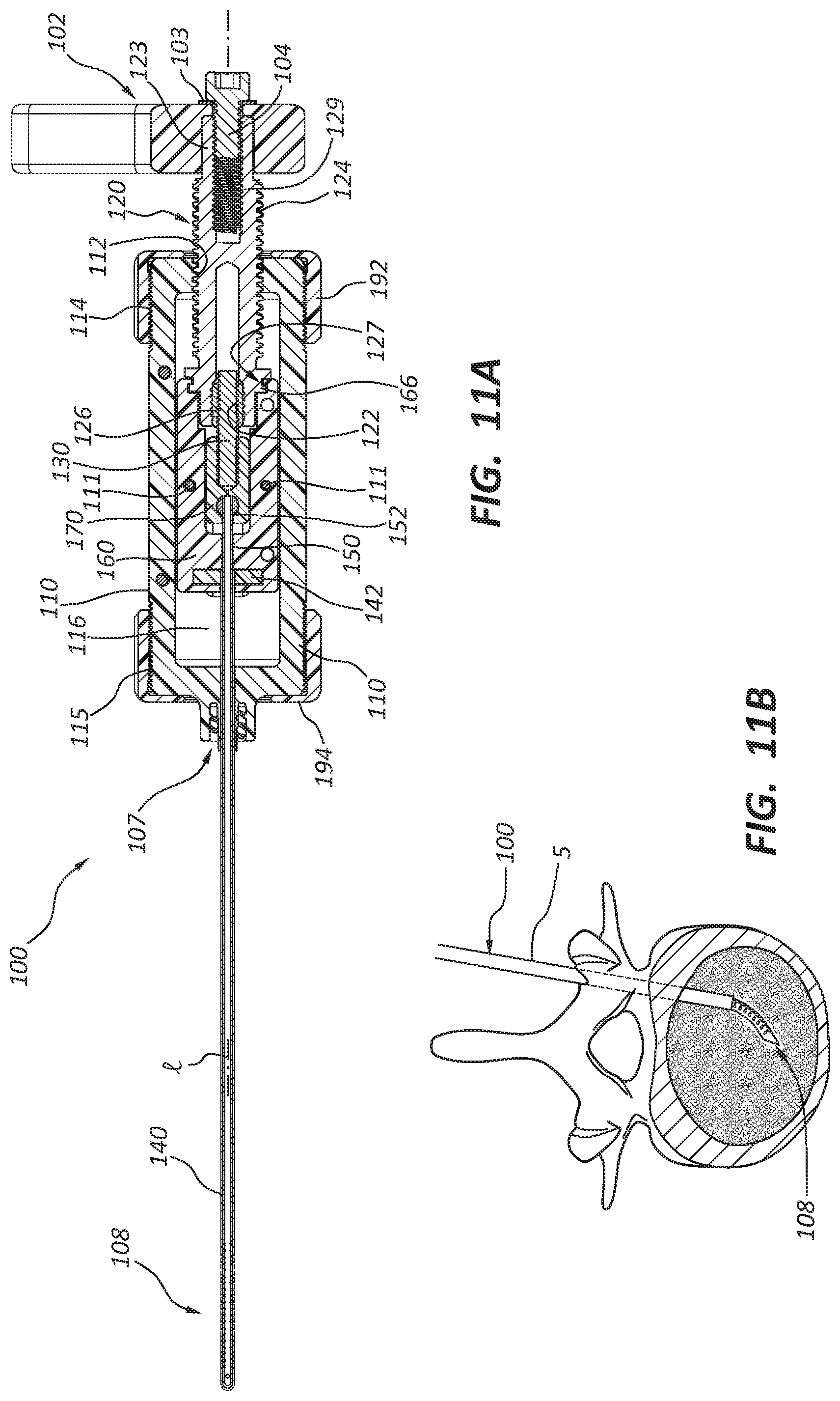
FIG. 11A is a cross-sectional view of the osteotome of FIG. 1 in a second configuration.
FIG. 11B depicts the osteotome of FIG. 1 in a vertebra of the patient when the osteotome is in the second configuration.
FIG. 12A is a cross-sectional view of the osteotome of FIG. 1 in a third configuration.
FIG. 12B depicts the osteotome of FIG. 1 in a vertebra of the patient when the osteotome is in the third configuration.
DETAILED DESCRIPTION
An osteotome may be used to create or expand a cavity within bone of a patient. For example, in some embodiments, a distal portion of an osteotome may be inserted into a bone (e.g., a vertebra) of the patient. Once the distal portion of the osteotome is disposed within the bone of the patient, the distal portion of the osteotome may be displaced. Such displacement may cut, grind, granulate, fragmentize, deform, displace, or otherwise alter the bone, thereby creating and/or expanding a cavity within the bone.
As the distal portion of the osteotome is displaced, the bone of the patient may exert one or more forces on the distal portion of the osteotome. For example, in some embodiments where the distal portion of the osteotome is transitioned from a linear configuration to a bent configuration without simultaneous advancement of the distal portion of the osteotome in a distal direction, the distal portion of the osteotome may contact bone that exerts one or more reactionary forces on the distal portion. Such force(s) may damage or weaken the osteotome.
In some embodiments described herein, the osteotome may be manipulated such that a distal portion of the osteotome is simultaneously advanced and articulated. For example, in some embodiments, rotation of a handle may cause the distal portion of the osteotome to simultaneously both (1) be advanced within the bone of the patient and (2) bend away from a longitudinal axis of the osteotome. Relative to other methods, the simultaneous advancement and articulation of a distal portion of an osteotome may reduce the magnitude of one or more forces that may act on the distal portion of the osteotome. Stated differently, simultaneous advancement and articulation of the distal portion may reduce one or more forces on the distal portion of the osteotome relative to other methods in which advancement and articulation are separated in time, thereby decreasing the risk of breakage or other damage to the osteotome.
The components of the embodiments as generally described and illustrated in the figures herein can be arranged and designed in a wide variety of different configurations. Thus, the following more detailed description of various embodiments, as represented in the figures, is not intended to limit the scope of the present disclosure, but is merely representative of various embodiments. While various aspects of the embodiments are presented in drawings, the drawings are not necessarily drawn to scale unless specifically indicated.
The phrase "coupled to" is broad enough to refer to any suitable coupling or other form of interaction between two or more entities. Two components may be coupled to each other even though they are not in direct contact with each other. For example, two components may be coupled to each other through an intermediate component. Two components are "fixedly coupled" to each other if neither component is displaceable relative to the other. The phrase "attached to" refers to interaction between two or more entities which are in direct contact with each other and/or are separated from each other only by a fastener of any suitable variety (e.g., an adhesive).
The terms "proximal" and "distal" are opposite directional terms. For example, the distal end of a device or component is the end of the component that is furthest from the practitioner during ordinary use. The proximal end refers to the opposite end, or the end nearest the practitioner during ordinary use.
FIGS. 1-5 provide various views of a medical device 100 (an osteotome) or portions thereof for creating or expanding a cavity within a bone of a patient. For example, FIG. 1 provides a first perspective view of the medical device 100. FIG. 2 provides a second perspective view of the medical device 100. FIG. 3 provides a first cross-sectional view of the medical device 100 through plane 3-3 of FIG. 1. FIG. 4 provides a cross-sectional perspective view of the medical device 100 through plane 4-4 of FIG. 1. FIG. 5 provides an exploded perspective view of the medical device 100. FIGS. 6-8 provide perspective (FIG. 6), bottom (FIG. 7), and cross-sectional (FIG. 8) views of a distal portion 108 of the medical device 100 in a fully retracted and straight configuration. FIG. 9 provides a side view of the distal portion 108 of the medical device 100 in a fully advanced and articulated configuration. Elements of the medical device 100 are also shown in FIGS. 10A-12B.
As shown in FIGS. 1-12B, the medical device 100 may include, among other elements, a handle 102, a housing 110, a first shaft 120, a second shaft 130, a third shaft 140, a fourth shaft 150, a shuttle 160, and a casing 170.
The handle 102 may be coupled to the first shaft 120 such that rotation of the handle 102 results in rotation of the first shaft 120. In some embodiments, the handle 102 is coupled to the first shaft 120 such that when the handle 102 is rotated, the first shaft 120 rotates at the same rate as the handle 102. Stated differently, as the handle 102 is rotated 360 degrees about a longitudinal axis (l), the first shaft 120 may also rotate 360 degrees about the longitudinal axis (l).
In the depicted embodiment, the handle 102 is coupled to the first shaft 120 by inserting a hexagonal proximal portion 123 of the first shaft 120 into a complementary hexagonal opening 106 on the handle 102. A fastener 104 (e.g., a bolt) may then be inserted through the handle 102 into a proximal opening 121 of the first shaft 120 such that the fastener 104 is threadably engaged with interior threads 129 disposed adjacent to a proximal end of the first shaft 120. In some embodiments, a washer 103 is disposed between the fastener 104 and the handle 102.
The housing 110 may be generally elongate in shape. In the depicted embodiment, the housing 110 includes interior threads 112 disposed adjacent the proximal end of the housing 110, a recess 116, a distal adaptor 107, proximal exterior threads 114, and distal exterior threads 115. The distal adaptor 107 (e.g., a male luer connection) may be configured to facilitate attachment to an introducer that has been inserted into a patient. The housing may encompass or partially encompass various components, such as the shuttle 160, the casing 170, and the second shaft 130.
In some embodiments, the housing 110 is formed from two separate portions (see FIG. 5) that are attached to one another. For example, in some embodiments, the medical device 100 includes one or more threaded caps 192, 194 that secure a first portion of the housing 110 to a second portion of the housing 110. A proximal threaded cap 192 may be configured to threadably engage with the proximal exterior threads 114, while a distal threaded cap 194 may be configured to threadably engage with the distal exterior threads 115 of the housing 110. The interaction between the threaded caps 192, 194 and the exterior threads 114, 115 of the housing 110 may secure a first portion of the housing 110 to the second portion of the housing 110.
The first shaft 120 may include exterior threads 124. The exterior threads 124 may theadably engage with the interior threads 112 of the housing 110 such that the first shaft 120 is threadably coupled to the housing 110. Due to the threaded interaction between the first shaft 120 and the housing 110, rotation of the handle 102 in a first (e.g., clockwise) direction may cause simultaneous rotation of the first shaft 120, thereby distally displacing the first shaft 120 with respect to the housing 110. As discussed below, the exterior threads 124 may have a pitch that is greater than the pitch of exterior threads 132 on the second shaft 130. In some embodiments, the exterior threads 124 of the first shaft 120 form a right-handed helix.
The first shaft 120 may be coupled to the shuttle 160 that is disposed within the housing 110. For example, the shuttle 160 may be rotatably (but not threadedly) coupled to the first shaft 120 such that rotation of the first shaft 120 in a first (e.g., clockwise) direction with respect to the housing 110 results in axial displacement of the shuttle 160 relative to the housing 110. More particularly, an inward-projecting ridge 166 adjacent the proximal end of the shuttle 160 may be disposed within an exterior slot 127 of the first shaft 120 such that axial displacement of the first shaft 120 results in an equal magnitude of axial displacement of the shuttle 160. In some embodiments, the shuttle 160 is formed from two separate components (e.g., halves) that are attached to one another, such as via screws 111.
The shuttle 160 may further include an aperture 162. The aperture 162 may be configured to permit extension of an arm of the casing 170 through the shuttle 160 for interaction with a recess 116 of the housing 110 as described in further detail below. The shuttle 160 may also include one or more recesses 164 that are designed to accommodate (e.g., secure) an anchor 142 at the proximal end of the third shaft 140. The shuttle 160 may be configured to travel back and forth within the housing 110 along the longitudinal axis of the medical device 100.
In some embodiments, the first shaft 120 further includes an inner sleeve 126 disposed adjacent to the distal end of the first shaft 120. The inner sleeve 126 may be coupled to the remainder of the first shaft 120 such that the inner sleeve 126 and the first shaft 120 rotate at the same rate. In other words, the inner sleeve 126 may be fixedly coupled to a remainder of the first shaft 120. The inner sleeve 126 may have a composition that differs from the composition of the remainder of the first shaft 120. For example, in some embodiments, the inner sleeve 126 is formed from a metal or metal alloy, while the remainder of the first shaft 120 is formed from a synthetic polymer (e.g., a plastic). The composition of the inner sleeve 126 may provide increased durability relative to the composition of the remainder of the first shaft 120. In other embodiments, there is no separate inner sleeve 126.
The first shaft 120 may further include interior threads 122 that are disposed adjacent the distal end of the first shaft 120. In the depicted embodiment, the interior threads 122 are disposed on an interior of the inner sleeve 126.
The second shaft 130 may be threadably coupled to the first shaft 120. For example, in the depicted embodiment, the interior threads 122 adjacent the distal end of the first shaft 120 may threadably engage with the exterior threads 132 of the second shaft 130. The interior threads 122 of the first shaft 120 and the exterior threads 132 of the second shaft 130 may each have a shorter pitch than the exterior threads 124 of the first shaft 120 and the interior threads 112 of the housing 110. In some embodiments, the exterior threads 132 of the second shaft 130 form a right-handed helix.
As the first shaft 120 is rotated in a first (e.g., clockwise) direction, the second shaft 130 may be prevented from rotating about the longitudinal axis (l) of the medical device by the casing 170 described in greater detail below. Thus, rotation of the first shaft 120 in a first direction may cause the first shaft 120 to move distally with respect to the second shaft 130 due to the difference in pitch between the threads 122, 132, and the threads 124, 112. Thus, rotation of the first shaft 120 with respect to the housing 110 may result in axial displacement of the casing 170 relative to the shuttle 160.
As shown in FIG. 5, in some embodiments, the casing 170 is generally T-shaped. The casing 170 may be formed from two separate components (e.g., halves) that are attached to one another. In some embodiments, a proximal portion of the casing 170 is fixedly coupled to the second shaft 130 (e.g., via an adhesive). A distal portion of the casing 170 may be coupled to a proximal end of the fourth shaft 150. For example, the casing 170 may be formed by attaching a first half of the casing 170 that includes a hemisphere-shaped indentation with a second half of the casing 170 that includes another hemisphere-shaped indentation. The indentations on each half of the casing 170 may cooperate to form a pocket (e.g., a spherical pocket) that accommodates a bulbous proximal end 152 (e.g., a spherical ball) of the fourth shaft 150. Due to this interaction, the proximal end 152 of the fourth shaft 150 may be axially displaced with the casing 170 as described in greater detail below. Stated differently, the proximal end 152 of the fourth shaft 150 may move with the casing 170 along the longitudinal axis (l) of the medical device 100.
The casing 170 may include one or more arms that are configured to interact with one or more recesses 116 within the housing 110. For example, in some embodiments, each arm of the T-shaped casing 170 may extend though an aperture 162 in the shuttle 160 to the recess 116 within the housing 110. The recess(es) 116 of the housing 110 may interact with the casing 170 to prevent rotation of both the casing 170 and the second shaft 130 relative to the housing 110.
The third shaft 140 may be a metallic shaft that extends from a proximal anchor 142 that is disposed (e.g., secured) within the recess(es) 164 of the shuttle 160 to a position at or adjacent to the distal end of the medical device 100. The third shaft 140 may include an elongate lumen that extends from a proximal opening in the anchor 142 to adjacent the distal end of the medical device 100. In some embodiments, the third shaft 140 may include a plurality of slots 144 (see FIGS. 6-9) adjacent its distal end.
The fourth shaft 150 may be a metallic shaft that extends distally from the bulbous proximal end 152 within the casing 170 to a position at or adjacent to the distal end of the medical device 100. In some embodiments, the fourth shaft 150 includes an elongate lumen. Like the third shaft 140, the fourth shaft 150 may include a plurality of slots 154 adjacent its distal end. In some embodiments, the slots 154 may be disposed opposite the slots 144 of the third shaft 140.
The fourth shaft 150 may be at least partially disposed within an elongate lumen of the third shaft 140. Stated differently, the third shaft 140 may be disposed around a distal portion of the fourth shaft 150.
The third shaft 140 and the fourth shaft 150 may together form an articulating distal portion 108 of the medical device 100. As shown in FIGS. 8 and 9, the fourth shaft 150 may be attached (e.g., welded) to the third shaft 140 at a position that is adjacent to a distal end of the third shaft 140 while the remainder of the fourth shaft 150 is unattached from the third shaft 140. In other words, a proximal portion of the fourth shaft 150 may be longitudinally displaceable relative to the third shaft 140. By displacing the proximal end of the fourth shaft 150 relative to the third shaft 140 as described in greater detail below, the articulating distal portion 108 of the medical device 100 may be displaced. More specifically, by displacing the proximal end of the fourth shaft 150 relative to the third shaft 140, the distal portion of the medical device 100 may transition from a linear configuration (FIGS. 6-8) to a non-linear configuration (FIG. 9) and vice versa.
The medical device 100 may be used in one or more medical procedures, such as procedures for creating or expanding a cavity within bone of a patient. Various stages of an exemplary procedure for creating or expanding a cavity within bone of a patient are shown in FIGS. 10A-12B. More particularly, FIG. 10A discloses a cross-sectional view of the medical device 100 in a first configuration. FIG. 10B shows the medical device 100 in the first configuration where the medical device 100 is at least partially disposed within an introducer 5. FIGS. 11A and 11B are analogous to FIGS. 10A and 10B, except that the medical device 100 is in a second configuration. FIGS. 12A and 12B similarly show the medical device 100 in a third configuration.
An exemplary medical procedure may involve obtaining a medical device, such as the medical device 100 (e.g., an osteotome) and inserting a distal region (e.g., a pointed distal tip) of the medical device 100 into bone of a patient. For instance, in some embodiments, a distal region of the medical device 100 is inserted through an introducer 5 into a vertebral body (see FIG. 10B) of a patient (e.g., a sedated human patient in the prone position). In some embodiments, the housing 110 of the medical device 100 may be coupled (e.g., attached) to the introducer 5 via the distal adaptor 107 prior to rotating the handle 102 and/or the first shaft 120 of the medical device 100 relative to the housing 110.
Once the distal end of the medical device 100 is disposed within bone of the patient (e.g., as shown in FIG. 10B), the practitioner may rotate the handle 102 about the longitudinal axis (l) of the medical device 100 in a first (e.g., clockwise direction). Due to the interaction of the handle 102 with the first shaft 120, such manipulation of the handle 102 of the medical device 100 causes rotation of the first shaft 120 relative to the housing 110. Rotation of the first shaft 120 relative to the housing 110 causes the first shaft 120 to be displaced in a distal direction relative to the housing 110 due to the interaction of the exterior threads 124 of the first shaft 120 with the interior threads 112 adjacent the proximal end of the housing 110.
Due to the interaction between the inward-projecting ridge 166 of the shuttle 160 and the exterior slot 127 of the first shaft 120, rotation of the first shaft 120 also causes the shuttle 160 to move distally with the first shaft 120 along the longitudinal axis (l) of the medical device 100. Stated differently, as a result of rotational input at the handle 102, the first shaft 120 and the shuttle 160 may move distally within the housing 110 at the same rate. In the depicted embodiment, the shuttle 160 does not rotate within the housing 110 about the longitudinal axis (l) of the medical device 100. Rather, because (1) the casing 170 does not rotate relative to the housing 110 due to the interaction between arms of the casing 170 and the recess 116 within the housing 110 and (2) rotation of the shuttle 160 is constrained by the casing 170, the shuttle 160 of the depicted embodiment cannot rotate about the longitudinal axis (l) of the medical device 100. Stated differently, rotation of the first shaft 120 relative to the housing 110 causes rotation of the inward-projecting ridge 166 within the exterior slot 127 of the first shaft 120.
Furthermore, as the proximal anchor 142 of the third shaft 140 is disposed within the recess 164 of the shuttle 160, the proximal portion of the third shaft 140 moves distally with both first shaft 120 and the housing 110. Stated differently, each of the first shaft 120, the shuttle 160, and the proximal portion third shaft 140 may move axially (e.g., distally) relative to the housing 110 at a first rate. In other words, the shuttle 160 and the third shaft 140 may be coupled to the first shaft 120 such that axial displacement of the first shaft 120 a first distance relative to the housing 110 results in axial displacement of the third shaft 140 and the shuttle 160 a distance relative to the housing 110 that is equal to the first distance.
Additionally, as the first shaft 120 is rotated relative to the housing 110, the interior threads 122 adjacent the distal end of the first shaft 120 may interact with the exterior threads 132 of the second shaft 130. More specifically, as the first shaft 120 is rotated relative to the housing 110, the first shaft 120 may be distally displaced relative to the second shaft 130 due to the interaction between the interior threads 122 of the first shaft 120 and the exterior threads 132 of the second shaft 130. Like the shuttle 160, the second shaft 130 in the depicted embodiment does not rotate within the housing 110 about the longitudinal axis (l) of the medical device 100. Rather, the second shaft 130 is fixedly coupled to the casing 170 and is thereby rotationally constrained within the housing 110. Thus, as a result of being rotationally constrained in this manner, rotation of the first shaft 120 causes the second shaft 130 to move proximally relative to the first shaft 120. Further, as the pitch of the exterior threads 124 of the first shaft 120 and the interior threads 112 of the housing 110 is greater than the pitch of the interior threads 122 and the exterior threads 132, the first shaft 120 may move both (1) proximally relative to the shuttle 160 and (2) distally relative to the housing 110. Stated differently, as the handle 102 is rotated, the second shaft 130 may move distally within the housing 110 at a second rate that is different (e.g., slower) than the first rate at which the first shaft 120, the shuttle 160, and/or the proximal portion of the third shaft 140 move distally within the housing 110. In this manner, the fourth shaft 150 may be coupled to the second shaft 130 such that axial displacement of the second shaft 130 a second distance relative to the housing 110 results in axial displacement of the fourth shaft 150 a distance relative to the housing 110 that is equal to the second distance.
As (1) the casing 170 is fixedly coupled to the second shaft 130 and (2) the fourth shaft 150 is coupled to the casing 170 due to the position of the bulbous proximal end 152 within the pockets of the casing 170, the casing 170 and the proximal portion of the fourth shaft 150 may move axially (e.g., distally) with the second shaft. Stated differently, the second shaft 130 and the fourth shaft 150 may move distally within the housing 110 at a second rate that is slower than the rate at which both the first shaft 120 and the proximal portion of the third shaft 140 move distally with respect to the housing 110.
As the proximal portion of the third shaft 140 moves distally with respect to the housing 110 at a rate that is greater than the rate at which the fourth shaft 150 moves distally with respect to the housing 110, a distal portion of the medical device 100 may transition from a linear configuration (FIGS. 6-8) to a non-linear configuration (FIG. 9).
For example, as the distance between the proximal anchor 142 of the third shaft 140 and the proximal bulbous end 152 of the fourth shaft 150 increases, the distal tip of the medical device 100 may be simultaneously displaced both (1) distally relative to the housing 110 and (2) laterally relative to the longitudinal axis of the medical device 100. Stated differently, as a result of rotation of the first shaft 120 relative to the housing 110, (1) the distal portion 108 of the medical device 100 may be articulated such that a distal tip of the medical device 100 is laterally displaced relative to a longitudinal axis (l) of the medical device 100 and (2) the distal portion 108 of the medical device 100 is displaced in an axial (e.g., distal) direction relative to the housing 110.
In the depicted embodiment, as the first shaft 120 is rotated relative to the housing 110, the distal portion 108 of the medical device 100 may transition from a linear configuration to a non-linear configuration such that (1) the slots 144 on the third shaft 140 are disposed on a concave side of a bend and (2) the slots 154 on the fourth shaft 150 are disposed on a convex side of the bend (see FIG. 9). From the perspective shown in FIGS. 10A, 11A, and 12A, the distal tip of the medical device 100 may be displaced away from the longitudinal axis and into the page. The transition from the linear configuration to the non-linear configuration may occur in a single plane. Stated differently, in some embodiments, movement of the distal portion 108 of the medical device 100 is limited to a single plane. By rotating the handle 102 and the first shaft 120 a selected amount, the articulating distal portion 108 may be bent to a selected degree.
In some embodiments, the process described above is reversible. Stated differently, the medical device 100 may transition from the non-linear configuration to the linear configuration by rotating the handle 102 and/or the first shaft 120 in a second direction (e.g., counterclockwise) that differs from the first direction.
Any methods disclosed herein include one or more steps or actions for performing the described method. The method steps and/or actions may be interchanged with one another. In other words, unless a specific order of steps or actions is required for proper operation of the embodiment, the order and/or use of specific steps and/or actions may be modified. Moreover, sub-routines or only a portion of a method described herein may be a separate method within the scope of this disclosure. Stated otherwise, some methods may include only a portion of the steps described in a more detailed method.
Reference throughout this specification to "an embodiment" or "the embodiment" means that a particular feature, structure, or characteristic described in connection with that embodiment is included in at least one embodiment. Thus, the quoted phrases, or variations thereof, as recited throughout this specification are not necessarily all referring to the same embodiment.
Similarly, it should be appreciated by one of skill in the art with the benefit of this disclosure that in the above description of embodiments, various features are sometimes grouped together in a single embodiment, figure, or description thereof for the purpose of streamlining the disclosure. This method of disclosure, however, is not to be interpreted as reflecting an intention that any claim requires more features than those expressly recited in that claim. Rather, as the following claims reflect, inventive aspects lie in a combination of fewer than all features of any single foregoing disclosed embodiment. Thus, the claims following this Detailed Description are hereby expressly incorporated into this Detailed Description, with each claim standing on its own as a separate embodiment. This disclosure includes all permutations of the independent claims with their dependent claims.
Recitation in the claims of the term "first" with respect to a feature or element does not necessarily imply the existence of a second or additional such feature or element. It will be apparent to those having skill in the art that changes may be made to the details of the above-described embodiments without departing from the underlying principles of the present disclosure.
* * * * *
References
D00000
D00001
D00002
D00003
D00004
D00005
D00006
D00007
D00008
D00009
D00010
D00011
D00012

XML
uspto.report is an independent third-party trademark research tool that is not affiliated, endorsed, or sponsored by the United States Patent and Trademark Office (USPTO) or any other governmental organization. The information provided by uspto.report is based on publicly available data at the time of writing and is intended for informational purposes only.
While we strive to provide accurate and up-to-date information, we do not guarantee the accuracy, completeness, reliability, or suitability of the information displayed on this site. The use of this site is at your own risk. Any reliance you place on such information is therefore strictly at your own risk.
All official trademark data, including owner information, should be verified by visiting the official USPTO website at www.uspto.gov. This site is not intended to replace professional legal advice and should not be used as a substitute for consulting with a legal professional who is knowledgeable about trademark law.