Modular plug-in connector, replaceable module printed circuit board
Werner , et al.
U.S. patent number 10,651,588 [Application Number 16/195,916] was granted by the patent office on 2020-05-12 for modular plug-in connector, replaceable module printed circuit board. This patent grant is currently assigned to PHOENIX CONTACT GMBH & CO. KG. The grantee listed for this patent is Phoenix Contact GmbH & Co. KG. Invention is credited to Klaus-Michael Bath, Thorsten Friedrich, Andreas Schrader, Ingo Werner.
| United States Patent | 10,651,588 |
| Werner , et al. | May 12, 2020 |
Modular plug-in connector, replaceable module printed circuit board
Abstract
A modular plug-in connector includes: at least one connection terminal; and a printed circuit board module housing which is connected to the at least one connection terminal. The printed circuit board module housing includes a recess for reversibly inserting a module printed circuit board, a voltage input terminal connectable to a voltage source, and a voltage supply contact that is electrically connected to the voltage input terminal. The module printed circuit board inserted in the recess is suppliable with electrical energy from the voltage input terminal vis-a-vis the voltage supply contact. The printed circuit board module housing includes a signal line terminal and a signal line contact electrically connected to the signal line terminal, such that data exchange between the signal line terminal and the module printed circuit board inserted into the recess occurs using the signal line contact.
| Inventors: | Werner; Ingo (Detmold, DE), Friedrich; Thorsten (Aerzen, DE), Bath; Klaus-Michael (Blomberg, DE), Schrader; Andreas (Delbrueck, DE) | ||||||||||
|---|---|---|---|---|---|---|---|---|---|---|---|
| Applicant: |
|
||||||||||
| Assignee: | PHOENIX CONTACT GMBH & CO.
KG (Blomberg, DE) |
||||||||||
| Family ID: | 60574317 | ||||||||||
| Appl. No.: | 16/195,916 | ||||||||||
| Filed: | November 20, 2018 |
Prior Publication Data
| Document Identifier | Publication Date | |
|---|---|---|
| US 20190165511 A1 | May 30, 2019 | |
Foreign Application Priority Data
| Nov 27, 2017 [BE] | 2017/5861 | |||
| Current U.S. Class: | 1/1 |
| Current CPC Class: | H01R 12/716 (20130101); H01R 12/515 (20130101); H01R 12/55 (20130101); H01R 13/514 (20130101); H01R 13/6658 (20130101); H01R 9/2408 (20130101); H05K 1/141 (20130101); H05K 2201/10189 (20130101) |
| Current International Class: | H01R 12/00 (20060101); H01R 12/71 (20110101); H01R 13/514 (20060101); H01R 9/24 (20060101); H01R 12/51 (20110101); H01R 12/55 (20110101); H05K 1/14 (20060101); H01R 13/66 (20060101) |
| Field of Search: | ;439/55 |
References Cited [Referenced By]
U.S. Patent Documents
| 4241381 | December 1980 | Cobaugh |
| 4582386 | April 1986 | Martens |
| 4686506 | August 1987 | Farago |
| 4786259 | November 1988 | Paul |
| 4808114 | February 1989 | Mohri |
| 5269708 | December 1993 | DeYoung et al. |
| 5584728 | December 1996 | Cheng |
| 5713766 | February 1998 | Davies |
| 5876239 | March 1999 | Morin |
| 5971813 | October 1999 | Kunz |
| 6116788 | September 2000 | Melchior |
| 6146181 | November 2000 | Plaza |
| 6276943 | August 2001 | Boutros |
| 6413121 | July 2002 | Hyland |
| 6468092 | October 2002 | Graff |
| 6524118 | February 2003 | Kikuchi |
| 6659806 | December 2003 | Shi et al. |
| 6674645 | January 2004 | Anzai |
| 6769939 | August 2004 | Neumann |
| 6783398 | August 2004 | Slack |
| 6997742 | February 2006 | Tung |
| 7458826 | December 2008 | Maatta |
| 7845969 | December 2010 | Stadler |
| 7942680 | May 2011 | MacDougall |
| 7950936 | May 2011 | Wang |
| 8102657 | January 2012 | Hiew |
| 8113864 | February 2012 | Chiang |
| 8174847 | May 2012 | Ohtsuji |
| 8216003 | July 2012 | Fujimoto |
| 8282424 | October 2012 | Weinmann |
| 8435047 | May 2013 | Patel |
| 8469718 | June 2013 | Kobayashi |
| 9325110 | April 2016 | Lostoski |
| 9362639 | June 2016 | Zhang |
| 9419391 | August 2016 | Bolouri-Saransar |
| 9466897 | October 2016 | Wu |
| 9768572 | September 2017 | Gelineau |
| 9819124 | November 2017 | Oberski |
| 9997851 | June 2018 | Ekrot |
| 10085355 | September 2018 | Giefers |
| 10170868 | January 2019 | Oyake |
| 2002/0056625 | May 2002 | Becker |
| 2007/0246256 | October 2007 | Eusterholz et al. |
| 2009/0035983 | February 2009 | Correll |
| 2010/0062617 | March 2010 | Bang et al. |
| 2013/0316552 | November 2013 | Sasano |
| 2014/0113503 | April 2014 | Barber et al. |
| 2018/0090886 | March 2018 | Jeon |
| 2019/0115699 | April 2019 | Dupuis |
| 101674706 | Mar 2010 | CN | |||
| 104321932 | Jan 2015 | CN | |||
| 107018636 | Aug 2017 | CN | |||
| 4412270 | Oct 1995 | DE | |||
| 201242180 | Oct 2012 | TW | |||
Assistant Examiner: Imas; Vladimir
Attorney, Agent or Firm: Leydig, Voit & Mayer, Ltd.
Claims
What is claimed is:
1. A modular plug-in connector, comprising: at least one connection terminal; and a printed circuit board module housing which is connected to the at least one connection terminal, the printed circuit board module housing comprising a recess configured for reversibly inserting a module printed circuit board, a voltage input terminal connectable to a voltage source, and a voltage supply contact that is electrically connected to the voltage input terminal, wherein the module printed circuit board inserted in the recess is suppliable with electrical energy from the voltage input terminal by the voltage supply contact, and wherein the printed circuit board module housing comprises a signal line terminal and a signal line contact electrically connected to the signal line terminal, such that data exchange between the signal line terminal and the module printed circuit board inserted into the recess occurs using the signal line contact.
2. The modular plug-in connector part according to claim 1, wherein the at least one connection terminal is electrically connected to the signal line contact so as to enable data ex-change between the connection terminal and the module printed circuit board.
3. The modular plug-in connector according to claim 1, wherein the printed circuit board module housing further comprises a receiving guide arranged in the recess such that the module printed circuit board is insertable between, on one side, the receiving guide, and, on an other side, the voltage supply contact and the signal line contact.
4. The modular plug-in connector according to claim 1, wherein the printed circuit board module housing further comprises a cover movable between an open position in which the recess is accessible and a closed position in which the recess is closed by the cover.
5. The modular plug-in connector according to claim 4, wherein the cover comprises metal such that the recess is protected from electromagnetic radiation by the cover when the cover is in its closed position.
6. The modular plug-in connector according to claim 1, wherein the printed circuit board module housing further comprises metal such that the recess is protected from electromagnetic radiation by the printed circuit board module housing.
7. The modular plug-in connector according to claim 1, wherein the modular plug-in connector comprises a printed circuit board terminal and the voltage input terminal is arranged on a bottom face of the printed circuit board module housing.
8. A modular plug-in connector, comprising: at least one connection terminal; and a printed circuit board module housing which is connected to the at least one connection terminal, the printed circuit board module housing comprising a recess configured for reversibly inserting a module printed circuit board, a voltage input terminal connectable to a voltage source, and a voltage supply contact that is electrically connected to the voltage input terminal, wherein the module printed circuit board inserted in the recess is suppliable with electrical energy from the voltage input terminal by the voltage supply contact, wherein the printed circuit board module housing comprises a signal line terminal and a signal line contact electrically connected to the signal line terminal, such that data exchange between the signal line terminal and the module printed circuit board inserted into the recess occurs using the signal line contact, wherein the printed circuit board module housing further comprises a receiving guide arranged in the recess such that the module printed circuit board is insertable between, on one side, the receiving guide, and, on an other side, the voltage supply contact and the signal line contact, and wherein the voltage supply contact is subjected to spring force such that the module printed circuit board positioned between the receiving guide and the voltage supply contact is subjected to force by the voltage supply contact in the direction of the receiving guide.
9. A modular plug-in connector, comprising: at least one connection terminal; and a printed circuit board module housing which is connected to the at least one connection terminal, the printed circuit board module housing comprising a recess configured for reversibly inserting a module printed circuit board, a voltage input terminal connectable to a voltage source, and a voltage supply contact that is electrically connected to the voltage input terminal, wherein the module printed circuit board inserted in the recess is suppliable with electrical energy from the voltage input terminal by the voltage supply contact, wherein the printed circuit board module housing comprises a signal line terminal and a signal line contact electrically connected to the signal line terminal, such that data exchange between the signal line terminal and the module printed circuit board inserted into the recess occurs using the signal line contact, wherein the printed circuit board module housing further comprises a receiving guide arranged in the recess such that the module printed circuit board is insertable between, on one side, the receiving guide, and, on an other side, the voltage supply contact and the signal line contact, and wherein the signal line contact is subjected to spring force such that the module printed circuit board positioned between the receiving guide and the signal line contact is subjected to force by the signal line contact in the direction of the receiving guide.
Description
CROSS-REFERENCE TO PRIOR APPLICATION
Priority is claimed to Belgian Patent Application No. BE 2017/5861, filed on Nov. 27, 2017, the entire disclosure of which is hereby incorporated by reference herein.
FIELD
The present invention relates to a plug-in connector comprising a replaceable module printed circuit board.
BACKGROUND
Electrical plug-in connectors are used to connect electrical conductors to a printed circuit board, for example. Depending on the embodiment, the electrical plug-in connector may be designed as a socket part or as a plug part. In the simplest embodiments of plug-in connectors, these are used merely for transmitting electrical power or for transmitting data and signals.
Electrical plug-in connectors that are fitted with processing electronics implemented in particular on a printed circuit board of the plug-in connector are also known. By means of the processing electronics, signals and data can be processed and forwarded. These data or signals may include, for example, an electrical voltage applied to a connection terminal of the plug-in connector, an electric current flowing through the connection terminal, or a temperature of the connection terminal.
If the requirements with regard to the processing electronics of the plug-in connector change, the plug-in connectors known from the prior art have to be replaced in their entirety, resulting in an increased cost of materials and a considerable amount of work for rewiring.
SUMMARY
In an embodiment, the present invention provides a modular plug-in connector, comprising: at least one connection terminal; and a printed circuit board module housing which is connected to the at least one connection terminal, the printed circuit board module housing comprising a recess configured for reversibly inserting a module printed circuit board, a voltage input terminal connectable to a voltage source, and a voltage supply contact that is electrically connected to the voltage input terminal, wherein the module printed circuit board inserted in the recess is suppliable with electrical energy from the voltage input terminal vis-a-vis the voltage supply contact, and wherein the printed circuit board module housing comprises a signal line terminal and a signal line contact electrically connected to the signal line terminal, such that data exchange between the signal line terminal and the module printed circuit board inserted into the recess occurs using the signal line contact.
BRIEF DESCRIPTION OF THE DRAWINGS
The present invention will be described in even greater detail below based on the exemplary figures. The invention is not limited to the exemplary embodiments. Other features and advantages of various embodiments of the present invention will become apparent by reading the following detailed description with reference to the attached drawings which illustrate the following:
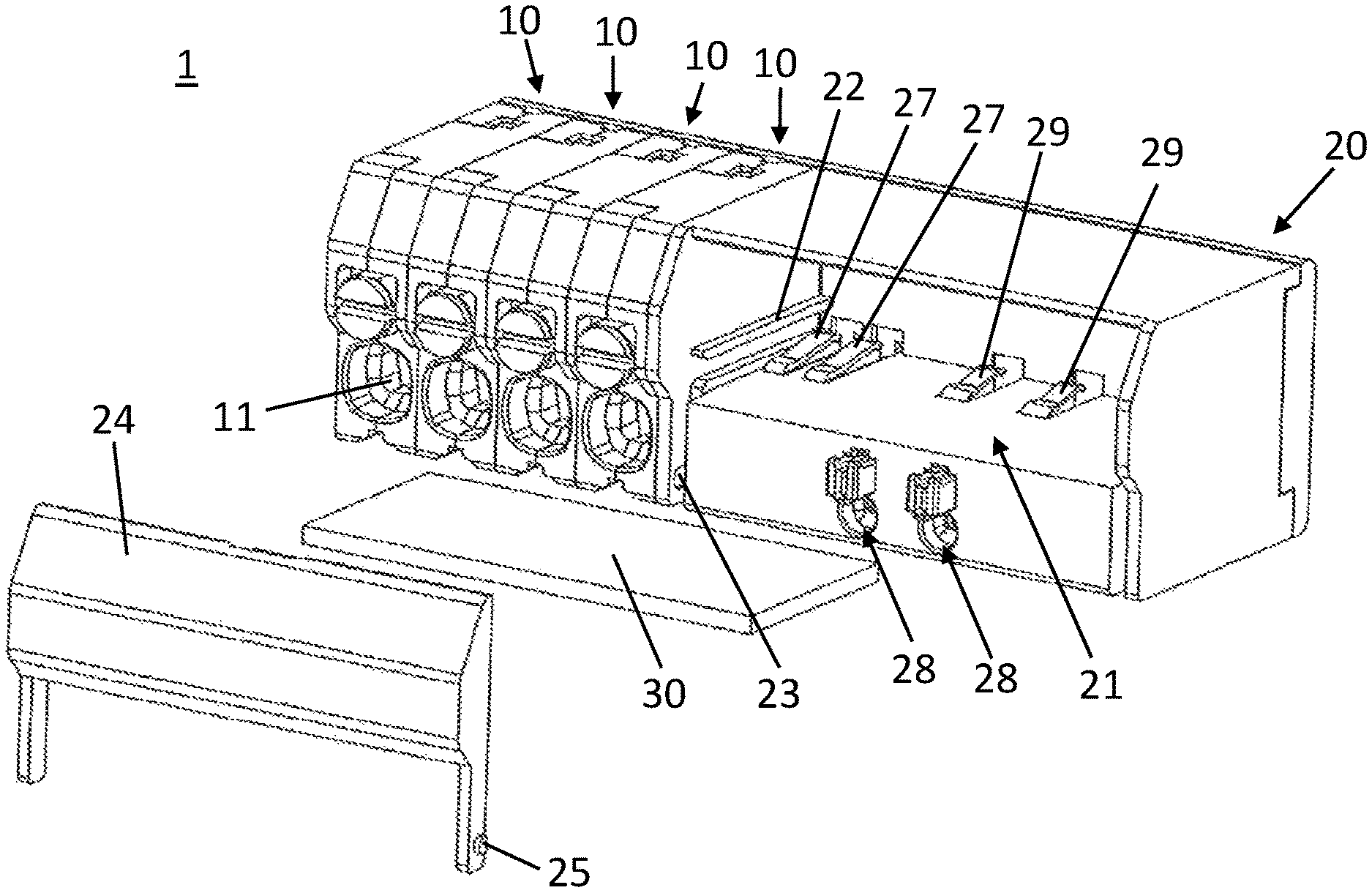
FIG. 1 is a perspective view of a modular plug-in connector according to the invention having an unmounted cover and a removed module printed circuit board;
FIG. 2 is a perspective view of the modular plug-in connector shown in FIG. 1 having a mounted cover;
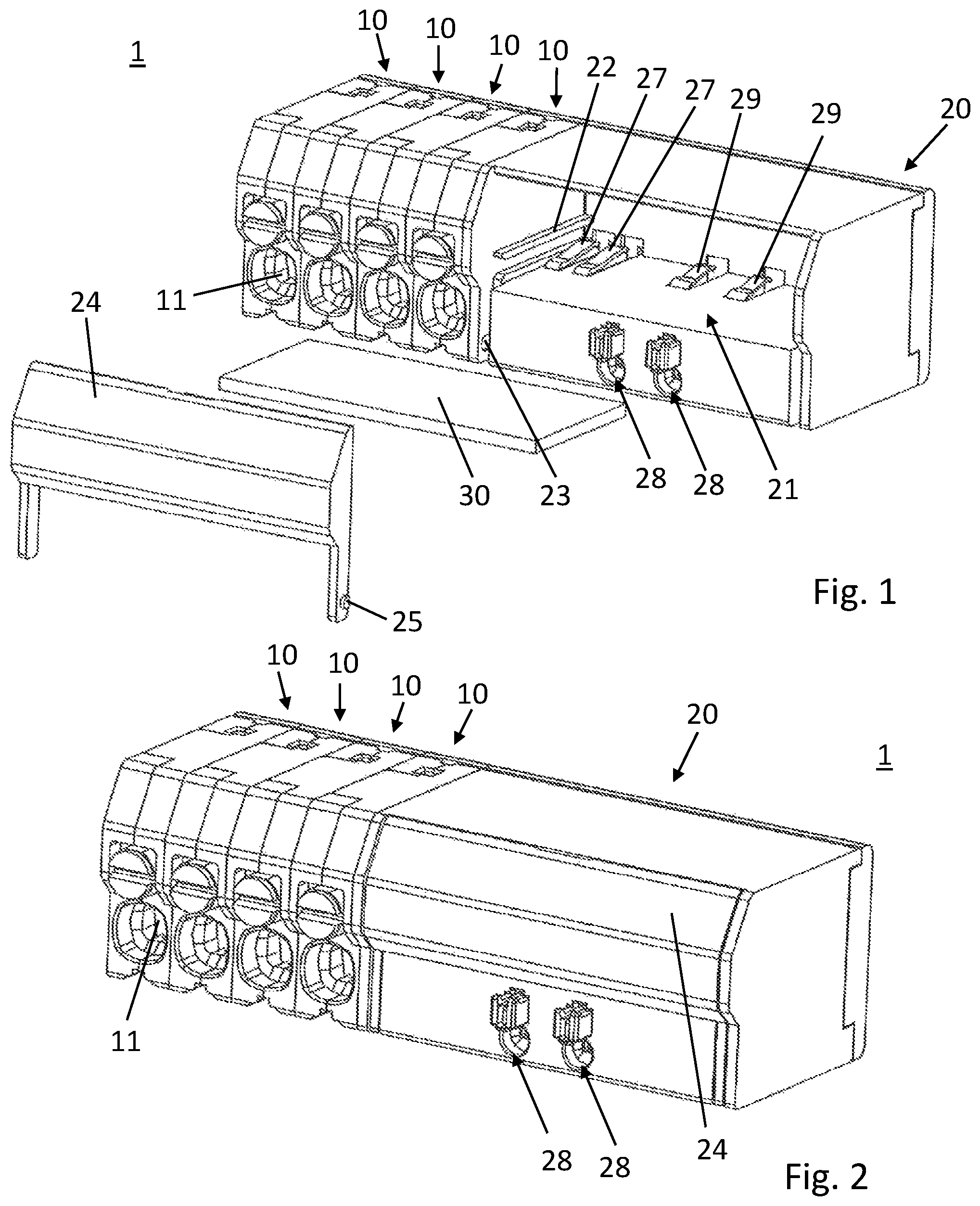
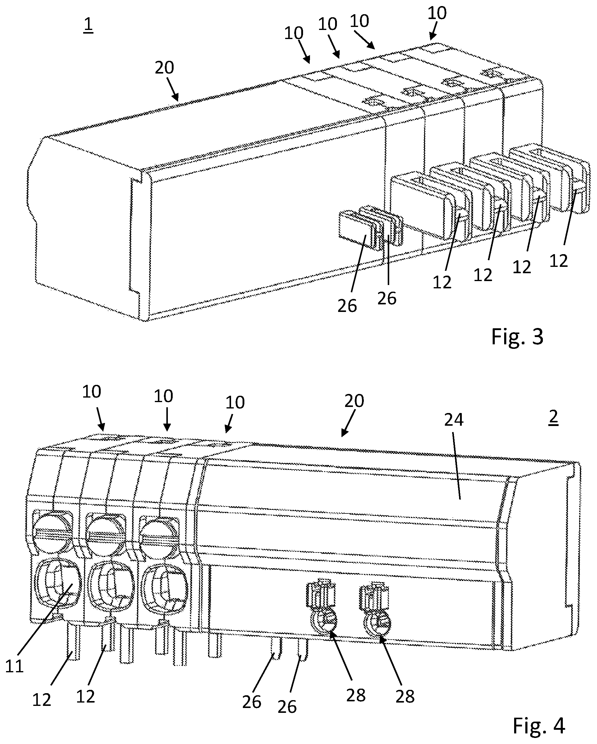
FIG. 3 is a perspective view of a rear face of the modular plug-in connector shown in FIG. 2; and
FIG. 4 is a perspective view of a modular plug-in connector designed as a printed circuit board terminal.
DETAILED DESCRIPTION
An aspect of the present invention provides a plug-in connector the functionality of which can be adapted to different needs.
In an embodiment, the present invention provides a modular plug-in connector which comprises at least one connection terminal and a printed circuit board module housing which is connected to the connection terminal. The modular plug-in connector is designed as a modular electrical plug-in connector. The printed circuit board module housing comprises a recess for reversibly inserting a module printed circuit board. The printed circuit board module housing further comprises a voltage input terminal for connection to a voltage source and comprises a voltage supply contact that is electrically connected to the voltage input terminal. A module printed circuit board inserted in the recess can be supplied with electrical energy by the voltage input terminal by means of the voltage supply contact. Moreover, the printed circuit board module housing comprises a signal line terminal and a signal line contact electrically connected to the signal line terminal, such that data exchange between the signal line terminal and the module printed circuit board inserted into the recess is made possible by means of the signal line contact.
The modular plug-in connector according to the invention is advantageous in that the functionality of the plug-in connector can easily be changed by replacing the module printed circuit board. Therefore, when changing the signal processing logic, the plug-in connector does not have to be replaced in its entirety, meaning that it is not necessary to electrically re-connect the plug-in connector to a printed circuit board, for example. Consequently, considerably less work is required.
Due to the reversible receipt of the module printed circuit board, the module printed circuit board can be easily replaced by or exchanged with another module printed circuit board.
The printed circuit board module housing is preferably made of an insulating material. The printed circuit board module housing preferably comprises an electrically insulating plastics material or an electrically insulating ceramic material.
The recess in the printed circuit board module housing is preferably designed as a receiving space in the printed circuit board module housing. More preferably, a guiding and/or positioning device is arranged in the recess, by means of which device a module printed circuit board is guided and/or positioned in the recess.
The voltage input terminal of the printed circuit board module housing may also be referred to as a power input terminal. The voltage contact device may also be referred to as a power contact device.
The module printed circuit board is preferably formed so as to comprise electrically conductive contact pads which are positioned in such a way that, when the module printed circuit board is inserted as intended, the contact pads are in electrical contact with the voltage contact device and with the signal line contact.
The modular plug-in connector is preferably designed in such a way that the at least one connection terminal is electrically connected to the signal line contact such that data exchange between the connection terminal and the module printed circuit board is made possible.
Data exchange from the connection terminal to the module printed circuit board and/or from the module printed circuit board to the connection terminal is made possible.
The modular plug-in connector is preferably designed in such a way that the printed circuit board module housing comprises a receiving guide arranged in the recess such that the module printed circuit board can be inserted between, on one side, the receiving guide and, on the other side, the voltage supply contact and the signal line contact.
By means of such an embodiment of the modular plug-in connector, it can be ensured that the module printed circuit board is positioned as intended and that the voltage supply contact and the signal line contact are reliably electrically contacted by the module printed circuit board.
The receiving guide is preferably designed as a guide bar, more preferably as two guide bars. The guide bars are preferably formed on lateral walls of the printed circuit board module housing and protrude into a receiving space of the recess.
The modular plug-in connector is preferably designed in such a way that the voltage supply contact is subjected to spring force such that a module printed circuit board positioned between the receiving guide and the voltage supply contact is subjected to force by means of the voltage supply contact in the direction of the receiving guide.
By means of such an embodiment of the modular plug-in connector, it is ensured that the voltage supply contact can be reliably electrically contacted by the module printed circuit board.
The modular plug-in connector is preferably designed in such a way that the signal line contact is subjected to spring force such that a module printed circuit board positioned between the receiving guide and the signal line contact is subjected to force by means of the signal line contact in the direction of the receiving guide.
By means of such an embodiment of the modular plug-in connector, it is ensured that the signal line contact can be reliably electrically contacted by the module printed circuit board.
The modular plug-in connector is preferably designed in such a way that the printed circuit board module housing comprises a cover which can be moved between an open position in which the recess is accessible and a closed position in which the recess is closed by means of the cover.
By means of such an embodiment of the modular plug-in connector, the recess, and thus the module printed circuit board positioned in the recess, is protected from undesirable contact and from contamination.
The modular plug-in connector is preferably designed in such a way that the cover comprises metal such that the recess is protected from electromagnetic radiation by means of the cover when said cover is in its closed position.
By means of such an embodiment of the modular plug-in connector, the recess, and thus the module printed circuit board positioned in the recess, is better protected from electromagnetic radiation.
Preferably, the cover consists of a metal. More preferably, a metal layer is embedded in the cover such that the outer layers of the cover consist of an insulating material (e.g. plastics material or ceramic material) and a metal layer is arranged between the outer layers.
The modular plug-in connector is preferably designed in such a way that the printed circuit board module housing comprises metal such that the recess is protected from electromagnetic radiation by means of the printed circuit board module housing.
By means of such an embodiment of the modular plug-in connector, the recess, and thus the module printed circuit board positioned in the recess, is better protected from electromagnetic radiation.
Preferably, the printed circuit board module housing consists of a metal. More preferably, a metal layer is embedded in the printed circuit board module housing such that the outer layers of the printed circuit board module housing consist of an insulating material (e.g. plastics material or ceramic material) and a metal layer is arranged between the outer layers.
The modular plug-in connector is preferably designed in such a way that the modular plug-in connector is designed as a printed circuit board terminal and the voltage input terminal is arranged on a bottom face of the printed circuit board module housing.
In the following description, identical reference numerals designate identical components or identical features, and therefore a description made with respect to one figure in relation to a component also applies to the other figures, so as to avoid a repeated description. Furthermore, individual features described in connection with one embodiment may also be used separately in other embodiments.
FIG. 1 is a perspective view of a modular plug-in connector 1 according to the invention having an unmounted cover 24 and a removed module printed circuit board 30. The modular plug-in connector 1 comprises at least one connection terminal 10 and a printed circuit board module housing 20. In the embodiment shown in FIG. 1, the modular plug-in connector 1 comprises four mutually adjacent and interconnected connection terminals 10. Each of the connection terminals 10 has an input terminal 11 and an output terminal 12 shown in FIG. 3. The input terminals 11 are respectively arranged on a front face of the modular plug-in connector 1, and the output terminals 12 are respectively arranged on a rear face of the modular plug-in connector 1.
It can be seen from FIG. 1 that the printed circuit board module housing 20, which is connected to the adjacent connection terminal 10 to the left in FIG. 1, has a recess 21. The recess 21 is designed as a receiving space 21. The recess 21 is used for reversibly inserting a module printed circuit board 30. This means that one module printed circuit board 30 can be replaced by another module printed circuit board 30.
In the recess 21, a voltage supply contact 27 is arranged which is electrically connected to a voltage input terminal 26 of the printed circuit board module housing 20 shown in FIG. 3. The voltage input terminal 26 is arranged on the rear face of the printed circuit board module housing 20. A module printed circuit board 30 inserted in the recess 21 can therefore be supplied with electrical energy by the voltage input terminal 26 by means of the voltage supply contact 27.
Furthermore, two signal line contacts 29 are arranged in the recess 21 which are electrically connected to two signal line terminals 28 of the printed circuit board module housing 20. The signal line terminals 28 are arranged on the front face of the printed circuit board module housing 20. Therefore, a module printed circuit board 30 inserted in the recess 21 can exchange data and/or signals with other electrical and/or electronic equipment by means of the signal line contacts 29 and the signal line terminals 28.
The signal line contacts 29 are furthermore preferably electrically connected to one or to a plurality of the connection terminals 10 such that data exchange between the connection terminal 10 or connection terminals 10 and the module printed circuit board 30 is made possible. For example, an electric current flowing through a connection terminal 10 can be determined by means of the module printed circuit board 30. Furthermore, when an appropriate sensor system is provided in the connection terminals 10, the temperature in the connection terminals 10, for example, can be determined and forwarded by means of the module printed circuit board 30 to a further piece of electronic equipment.
It can be seen from FIG. 1 that a receiving guide 22 is arranged in the recess 21 in the printed circuit board module housing 20. The receiving guide 22 in this case is designed in the form of guide bars 22. One guide bar is arranged on an inner face of a lateral wall of the printed circuit board module housing 20 and a further guide bar of the receiving guide 22 is arranged on an inner face of an opposite lateral wall of the printed circuit board module housing.
The module printed circuit board 30 can be inserted or pushed in between, on one side, the receiving guide 22 and, on the other side, the voltage supply contact 27 and the signal line contacts 29. The voltage supply contact 27 and the signal line contacts 29 are subjected to spring force such that a module printed circuit board 30 positioned between the receiving guide 22 and the voltage supply contact 27 and the signal line contacts 29 is subjected to force by means of the voltage supply contact 27 and the signal line contact 29 in the direction of the receiving guide 22. Reliable electrical contacting of the module printed circuit board 30 by means of the voltage supply contact 27 and the signal line contact 29 is thus ensured.
Although not apparent from FIG. 1, electrical contact devices in the form of contact pads are arranged at corresponding points on the module printed circuit board 30 and are in electrical contact with the voltage supply contact 27 and the signal line contacts 29 when the module printed circuit board 30 is inserted as intended in the recess 21.
The modular plug-in connector 1 according to the invention further comprises a cover 24 which can be moved between an open position in which the recess 21 is accessible and a closed position (shown in FIG. 2) in which the recess 21 is closed by means of the cover 24. For this purpose, the cover 24 comprises two bearing journals 25, which are inserted into corresponding bearing openings 23 in the printed circuit board module housing 20 such that the cover 24 is pivotally mounted.
The cover 24 is preferably made of an electrically insulating material, such as a plastics material or an electrically insulating ceramic material. A metal layer is preferably provided in the cover 24 such that the recess 21 is protected from electromagnetic radiation by means of the cover 24.
For this purpose, the printed circuit board module housing 20 may also comprise a metal layer such that the recess 21 is also protected from electromagnetic radiation by means of the printed circuit board module housing 20.
FIG. 4 shows a modular plug-in connector 2 which is designed as a printed circuit board terminal 2. The printed circuit board terminal 2 differs from the modular plug-in connector 1 shown in FIG. 1 in that the output terminals 12 of the connection terminals 10 and also the voltage input terminals 26 of the printed circuit board module housing 20 are arranged on a bottom face of the printed circuit board terminal 2 such that they can be inserted into corresponding openings in a printed circuit board and can be electrically contacted therewith, for example by means of soldering. The design of the printed circuit board terminal 2 shown in FIG. 4 is otherwise identical to the design of the modular plug-in connector 1 shown in FIGS. 1 to 3.
While the invention has been illustrated and described in detail in the drawings and foregoing description, such illustration and description are to be considered illustrative or exemplary and not restrictive. It will be understood that changes and modifications may be made by those of ordinary skill within the scope of the following claims. In particular, the present invention covers further embodiments with any combination of features from different embodiments described above and below. Additionally, statements made herein characterizing the invention refer to an embodiment of the invention and not necessarily all embodiments.
The terms used in the claims should be construed to have the broadest reasonable interpretation consistent with the foregoing description. For example, the use of the article "a" or "the" in introducing an element should not be interpreted as being exclusive of a plurality of elements. Likewise, the recitation of "or" should be interpreted as being inclusive, such that the recitation of "A or B" is not exclusive of "A and B," unless it is clear from the context or the foregoing description that only one of A and B is intended. Further, the recitation of "at least one of A, B and C" should be interpreted as one or more of a group of elements consisting of A, B and C, and should not be interpreted as requiring at least one of each of the listed elements A, B and C, regardless of whether A, B and C are related as categories or otherwise. Moreover, the recitation of "A, B and/or C" or "at least one of A, B or C" should be interpreted as including any singular entity from the listed elements, e.g., A, any subset from the listed elements, e.g., A and B, or the entire list of elements A, B and C.
LIST OF REFERENCE NUMERALS
1 modular plug-in connector 2 printed circuit board terminal 10 connection terminal 11 input terminal (of the connection terminal) 12 output terminal (of the connection terminal) 20 printed circuit board module housing 21 recess (in the printed circuit board module housing) 22 receiving guide 23 bearing opening (in the printed circuit board module housing) 24 cover (of the printed circuit board module housing) 25 bearing journal (of the cover) 26 voltage input terminal/power input terminal (of the printed circuit board module housing) 27 voltage supply contact/power supply contact 28 signal line terminal (of the printed circuit board module housing) 29 signal line contact 30 module printed circuit board
* * * * *
D00000
D00001
D00002
XML
uspto.report is an independent third-party trademark research tool that is not affiliated, endorsed, or sponsored by the United States Patent and Trademark Office (USPTO) or any other governmental organization. The information provided by uspto.report is based on publicly available data at the time of writing and is intended for informational purposes only.
While we strive to provide accurate and up-to-date information, we do not guarantee the accuracy, completeness, reliability, or suitability of the information displayed on this site. The use of this site is at your own risk. Any reliance you place on such information is therefore strictly at your own risk.
All official trademark data, including owner information, should be verified by visiting the official USPTO website at www.uspto.gov. This site is not intended to replace professional legal advice and should not be used as a substitute for consulting with a legal professional who is knowledgeable about trademark law.