Cutting tool assemblies including superhard working surfaces, cutting tool mounting assemblies, material-removing machines including the same, and methods of use
Weaver , et al.
U.S. patent number 10,648,330 [Application Number 15/266,355] was granted by the patent office on 2020-05-12 for cutting tool assemblies including superhard working surfaces, cutting tool mounting assemblies, material-removing machines including the same, and methods of use. This patent grant is currently assigned to US SYNTHETIC CORPORATION. The grantee listed for this patent is US SYNTHETIC CORPORATION. Invention is credited to Regan Leland Burton, Gary Eugene Weaver.


View All Diagrams
| United States Patent | 10,648,330 |
| Weaver , et al. | May 12, 2020 |
Cutting tool assemblies including superhard working surfaces, cutting tool mounting assemblies, material-removing machines including the same, and methods of use
Abstract
Embodiments of the invention are directed to cutting tool assemblies, cutting tool mounting assemblies, material-removing machines that include cutting tool assemblies and/or cutting tool mounting assemblies, and methods of use and operation thereof. In some embodiments, the various assemblies described herein may be used in material-removing machines that may remove target material.
| Inventors: | Weaver; Gary Eugene (Conroe, TX), Burton; Regan Leland (Saratoga Springs, UT) | ||||||||||
|---|---|---|---|---|---|---|---|---|---|---|---|
| Applicant: |
|
||||||||||
| Assignee: | US SYNTHETIC CORPORATION (Orem,
UT) |
||||||||||
| Family ID: | 70612683 | ||||||||||
| Appl. No.: | 15/266,355 | ||||||||||
| Filed: | September 15, 2016 |
Related U.S. Patent Documents
| Application Number | Filing Date | Patent Number | Issue Date | ||
|---|---|---|---|---|---|
| 62232732 | Sep 25, 2015 | ||||
| Current U.S. Class: | 1/1 |
| Current CPC Class: | E21C 35/183 (20130101); E21C 35/19 (20130101); E21C 35/193 (20130101); E01C 23/088 (20130101); E21C 25/10 (20130101); E21C 35/191 (20200501) |
| Current International Class: | E21C 35/19 (20060101); E21C 35/193 (20060101); E21C 35/183 (20060101); E21C 35/18 (20060101); E21C 25/10 (20060101); E01C 23/088 (20060101) |
| Field of Search: | ;299/102-106,110,111,113 |
References Cited [Referenced By]
U.S. Patent Documents
| 2665893 | January 1954 | Ball |
| 3342532 | September 1967 | Krekeler |
| 3544166 | December 1970 | Proctor |
| 3671075 | June 1972 | Bland et al. |
| 3695726 | October 1972 | Krekeler |
| 3751114 | August 1973 | Davis |
| 3785021 | January 1974 | Norgren et al. |
| 3841708 | October 1974 | Kniff |
| D238243 | December 1975 | Polivka |
| 3958832 | May 1976 | Sigott et al. |
| 4006936 | February 1977 | Crabiel |
| 4083644 | April 1978 | Friedline et al. |
| 4140189 | February 1979 | Garner |
| 4193638 | March 1980 | Heckenhauer |
| 4200159 | April 1980 | Jurgens et al. |
| 4299424 | November 1981 | LeBegue et al. |
| 4303136 | December 1981 | Ball |
| 4335921 | June 1982 | Swisher et al. |
| 4337980 | July 1982 | Krekeler |
| 4340325 | July 1982 | Gowanlock et al. |
| D270059 | August 1983 | Wilkins |
| D271497 | November 1983 | Green |
| 4484644 | November 1984 | Cook et al. |
| 4580930 | April 1986 | Zinner et al. |
| 4605343 | August 1986 | Hibbs, Jr. et al. |
| 4655508 | April 1987 | Tomlinson |
| 4678237 | July 1987 | Collin |
| 4679858 | July 1987 | Tank |
| D296107 | June 1988 | Andersson |
| 4765687 | August 1988 | Parrott |
| 4784023 | November 1988 | Dennis et al. |
| 4787466 | November 1988 | Tomlinson et al. |
| 4836178 | June 1989 | Tomlinson |
| 4850649 | July 1989 | Beach et al. |
| 4880278 | November 1989 | Tomlinson |
| 4902073 | February 1990 | Tomlinson et al. |
| D307279 | April 1990 | Vincent |
| 4913125 | April 1990 | Bunting |
| D311747 | October 1990 | Mihic |
| 5007685 | April 1991 | Beach et al. |
| 5060739 | October 1991 | Griffin et al. |
| 5090491 | February 1992 | Tibbitts et al. |
| 5318351 | June 1994 | Walker |
| 5378050 | January 1995 | Kammerer |
| 5417475 | May 1995 | Graham et al. |
| 5431239 | July 1995 | Tibbitts et al. |
| 5605382 | February 1997 | Massa et al. |
| 5649604 | July 1997 | Fuller et al. |
| 5690393 | November 1997 | Massa et al. |
| 5881830 | March 1999 | Cooley |
| 5906245 | May 1999 | Tibbitts et al. |
| 6089123 | July 2000 | Chow et al. |
| 6213931 | April 2001 | Twardowski et al. |
| 6283844 | September 2001 | Tank |
| 6485104 | November 2002 | Keller et al. |
| 6779850 | August 2004 | Schibeci et al. |
| 7108212 | September 2006 | Latham |
| D558802 | January 2008 | Nicholas |
| D616003 | May 2010 | Ueda et al. |
| 7866418 | January 2011 | Bertagnolli et al. |
| 7998573 | August 2011 | Qian et al. |
| 8034136 | October 2011 | Sani |
| 8047260 | November 2011 | Uno et al. |
| 8079785 | December 2011 | Nicholas |
| 8236074 | August 2012 | Bertagnolli et al. |
| D666640 | September 2012 | Cox et al. |
| 8567533 | October 2013 | Myers et al. |
| 8672415 | May 2014 | Neilson et al. |
| 8727044 | May 2014 | Qian et al. |
| 8789894 | July 2014 | Claesson et al. |
| 9017438 | April 2015 | Miess et al. |
| 9027675 | May 2015 | Jones et al. |
| 9028008 | May 2015 | Bookhamner et al. |
| 9238893 | January 2016 | Latham et al. |
| 9272392 | March 2016 | Mukhopadhyay et al. |
| 9272814 | March 2016 | Carver et al. |
| 9303511 | April 2016 | George et al. |
| 9382794 | July 2016 | Latham et al. |
| 9434091 | September 2016 | Burton et al. |
| 9487847 | November 2016 | Mukhopadhyay et al. |
| 9593577 | March 2017 | Ries et al. |
| D809031 | January 2018 | Burton |
| 10018041 | July 2018 | Wachsmann et al. |
| 10323514 | June 2019 | Burton et al. |
| 10408057 | September 2019 | Myers et al. |
| 2001/0040053 | November 2001 | Beuershausen et al. |
| 2002/0153175 | October 2002 | Ojanen et al. |
| 2003/0234569 | December 2003 | Dawood et al. |
| 2005/0082898 | April 2005 | Keller et al. |
| 2006/0033379 | February 2006 | Frear et al. |
| 2006/0087169 | April 2006 | Hesse et al. |
| 2007/0090679 | April 2007 | Ojanen et al. |
| 2008/0030065 | February 2008 | Frear et al. |
| 2008/0035383 | February 2008 | Hall |
| 2008/0036280 | February 2008 | Hall et al. |
| 2008/0202819 | August 2008 | Fader |
| 2008/0250724 | October 2008 | Hall et al. |
| 2008/0309146 | December 2008 | Hall et al. |
| 2010/0052406 | March 2010 | Beach et al. |
| 2010/0194176 | August 2010 | Lucek et al. |
| 2010/0244545 | September 2010 | Hall et al. |
| 2010/0326741 | December 2010 | Patel |
| 2011/0132667 | June 2011 | Smallman et al. |
| 2011/0148178 | June 2011 | Lehnert |
| 2011/0233987 | September 2011 | Maushart et al. |
| 2011/0266070 | November 2011 | Scott et al. |
| 2012/0043138 | February 2012 | Myers et al. |
| 2012/0138370 | June 2012 | Mukhopadhyay |
| 2012/0160573 | June 2012 | Myers et al. |
| 2012/0175939 | July 2012 | O'Neill et al. |
| 2012/0274123 | November 2012 | Ball |
| 2012/0279786 | November 2012 | Cox |
| 2013/0052481 | February 2013 | Konyashin |
| 2013/0092451 | April 2013 | Mukhopadhyay |
| 2013/0092452 | April 2013 | Mukhopadhyay et al. |
| 2013/0322975 | December 2013 | Tan et al. |
| 2014/0110991 | April 2014 | Sollami |
| 2014/0175853 | June 2014 | Warren |
| 2014/0225418 | August 2014 | Lachmann et al. |
| 2014/0240634 | August 2014 | Matsuzaki |
| 2014/0339879 | November 2014 | Burton et al. |
| 2014/0339883 | November 2014 | Burton et al. |
| 2015/0035342 | February 2015 | Jonker |
| 2015/0114727 | April 2015 | Heuser |
| 2015/0176408 | June 2015 | Latham |
| 2015/0176409 | June 2015 | Latham |
| 2015/0240635 | August 2015 | Lachmann et al. |
| 2015/0314483 | November 2015 | Miess et al. |
| 2016/0102550 | April 2016 | Swope et al. |
| 2016/0273356 | September 2016 | Ojanen et al. |
| 2016/0332269 | November 2016 | Prezlock et al. |
| 2013101370 | Nov 2013 | AU | |||
| 102108866 | Jun 2011 | CN | |||
| 202073564 | Dec 2011 | CN | |||
| 203081445 | Jul 2013 | CN | |||
| 1481278 | Jul 1977 | GB | |||
| 2170843 | Aug 1986 | GB | |||
| 2177144 | Jan 1987 | GB | |||
| 2193740 | Feb 1988 | GB | |||
| WO 2010/083015 | Jul 2010 | WO | |||
| WO 2012/130870 | Oct 2012 | WO | |||
| WO 2016/071001 | May 2016 | WO | |||
Other References
|
Advisory Action received for U.S. Appl. No. 14/266,437 dated Mar. 24, 2017. cited by applicant . Non-Final Office Action for U.S. Appl. No. 14/266,437 dated Apr. 21, 2017. cited by applicant . Non-Final Office Action received for U.S. Appl. No. 14/275,574 dated Apr. 7, 2017. cited by applicant . Non-Final Office Action for U.S. Appl. No. 29/555,279 dated Mar. 24, 2017. cited by applicant . Notice of Allowance received for U.S. Appl. No. 29/555,269 dated Apr. 6, 2017. cited by applicant . Notice of Allowance received for U.S. Appl. No. 29/555,281 dated Apr. 12, 2017. cited by applicant . Supplemental Notice of Allowance for U.S. Appl. No. 29/555,269 dated Apr. 28, 2017. cited by applicant . Notice of Allowance for U.S. Appl. No. 29/540,584 dated May 8, 2017. cited by applicant . Notice of Allowance for U.S. Appl. No. 29/540,597 dated May 8, 2017. cited by applicant . Supplemental Notice of Allowance for U.S. Appl. No. 29/540,597 dated Jun. 1, 2017. cited by applicant . U.S. Appl. No. 12/961,787, filed Dec. 7, 2010, Mukhopadhyay et al. cited by applicant . U.S. Appl. No. 13/027,954, filed Feb. 15, 2011, Miess et al. cited by applicant . U.S. Appl. No. 13/070,636, filed Mar. 24, 2011, Qian et al. cited by applicant . U.S. Appl. No. 13/100,388, filed May 4, 2011, Jones et al. cited by applicant . U.S. Appl. No. 13/275,372, filed Oct. 18, 2011, Mukhopadhyay et al. cited by applicant . U.S. Appl. No. 13/648,913, filed Oct. 10, 2012, Mukhopadhyay et al. cited by applicant . U.S. Appl. No. 13/765,027, filed Feb. 12, 2013, Carver, et al. cited by applicant . U.S. Appl. No. 13/795,027, filed Mar. 12, 2013, Mukhopadhyay et al. cited by applicant . U.S. Appl. No. 61/824,022, filed May 16, 2013, Burton et al. cited by applicant . U.S. Appl. No. 61/824,007, filed May 16, 2013, Burton et al. cited by applicant . U.S. Appl. No. 14/266,437, filed Apr. 30, 2014, Miess et al. cited by applicant . U.S. Appl. No. 14/273,360, filed May 8, 2014, Burton et al. cited by applicant . U.S. Appl. No. 14/275,574, filed May 12, 2014, Burton et al. cited by applicant . U.S. Appl. No. 62/030,525, filed Jul. 29, 2014, Myers et al. cited by applicant . U.S. Appl. No. 14/811,699, filed Jul. 28, 2015, Myers et al. cited by applicant . U.S. Appl. No. 62/232,732, filed Sep. 25, 2015, Weaver et al. cited by applicant . U.S. Appl. No. 29/540,584, filed Sep. 25, 2015, Weaver. cited by applicant . U.S. Appl. No. 29/540,597, filed Sep. 25, 2015, Weaver. cited by applicant . U.S. Appl. No. 29/555,269, filed Feb. 19, 2016, Burton. cited by applicant . U.S. Appl. No. 29/555,279, filed Feb. 19, 2016, Burton. cited by applicant . U.S. Appl. No. 29/555,281, filed Feb. 19, 2016, Burton. cited by applicant . International Search Report and Written Opinion from International Application No. PCT/US2014/037708 dated Oct. 30, 2014. cited by applicant . International Search Report and Written Opinion from International Application No. PCT/US2014/037381 dated Oct. 30, 2014. cited by applicant . International Search Report and Written Opinion for International Application No. PCT/US2015/027830 dated Jul. 14, 2015. cited by applicant . Roepke et al.; "Drag Bit Cutting Characteristics Using Sintered Diamond Inserts" Report of Investigations 8802; Bureau of Mines Report of Investigations/ 1983; (1983) 35 pages. cited by applicant . U.S. Appl. No. 14/273,360, Jun. 12, 2015, Restriction Requirement. cited by applicant . U.S. Appl. No. 14/273,360, Oct. 22, 2015, Office Action. cited by applicant . U.S. Appl. No. 14/273,360, Mar. 7, 2016, Office Action. cited by applicant . U.S. Appl. No. 14/273,360, May 18, 2016, Notice of Allowance. cited by applicant . U.S. Appl. No. 14/273,360, Aug. 10, 2016, Supplemental Notice of Allowance. cited by applicant . Final Office Action for U.S. Appl. No. 14/266,437 dated Dec. 12, 2016. cited by applicant . Final Office Action for U.S. Appl. No. 14/275,574 dated Nov. 29, 2016. cited by applicant . Issue Notification for U.S. Appl. No. 14/273,360 dated Aug. 17, 2016. cited by applicant . Non-Final Office Action for U. S. Appl. No. 14/266,437 dated Jun. 9, 2016. cited by applicant . U.S. Appl. No. 13/070,636, filed Mar. 24, 2011. cited by applicant . U.S. Appl. No. 15/238,486, filed Aug. 16, 2016. cited by applicant . U.S. Appl. No. 61/824,022, filed May 16, 2013. cited by applicant . Non-Final Office Action for U.S. Appl. No. 14/275,574 dated Apr. 6, 2016. cited by applicant . Advisory Action received for U.S. Appl. No. 14/275,574 dated Mar. 9, 2017. cited by applicant . Final Office Action for U.S. Appl. No. 14/266,437 dated Nov. 15, 2017. cited by applicant . Final Office Action for U.S. Appl. No. 15/238,486 dated Feb. 26, 2018. cited by applicant . Issue Notification for U.S. Appl. No. 29/540,584 dated Sep. 14, 2017. cited by applicant . Issue Notification for U.S. Appl. No. 29/540,597 dated Sep. 6, 2017. cited by applicant . Issue Notification for U.S. Appl. No. 29/555,279 dated Jan. 10, 2018. cited by applicant . Non-Final Office Action for U.S. Appl. No. 14/266,437 dated Mar. 28, 2018. cited by applicant . Non-Final Office Action for U.S. Appl. No. 14/811,699 dated Nov. 29, 2017. cited by applicant . Non-Final Office Action for U.S. Appl. No. 15/238,486 dated Aug. 17, 2017. cited by applicant . Notice of Allowance for U.S. Appl. No. 14/275,574 dated Jan. 24, 2018. cited by applicant . Notice of Allowance for U.S. Appl. No. 14/275,574 dated Sep. 26, 2017. cited by applicant . Notice of Allowance for U.S. Appl. No. 29/555,279 dated Aug. 31, 2017. cited by applicant . Notice of Allowance for U.S. Appl. No. 29/555,281 dated Jan. 4, 2018. cited by applicant . Supplemental Notice of Allowability for U.S. Appl. No. 29/555,279 dated Jan. 2, 2018. cited by applicant . Supplemental Notice of Allowance for U.S. Appl. No. 29/540,584 dated Sep. 7, 2017. cited by applicant . Supplemental Notice of Allowance for U.S. Appl. No. 29/540,597 dated Aug. 25, 2017. cited by applicant . Supplemental Notice of Allowance for U.S. Appl. No. 29/555,281 dated Feb. 9, 2018. cited by applicant . Supplemental Notice of Allowance for U.S. Appl. No. 29/555,281 dated Jun. 12, 2017. cited by applicant . Final Office Action for U.S. Appl. No. 14/266,437 dated Sep. 18, 2018. cited by applicant . Final Office Action for U.S. Appl. No. 14/811,699 dated Jul. 10, 2018. cited by applicant . Issue Notification for U.S. Appl. No. 29/555,281 dated Aug. 29, 2018. cited by applicant . Notice of Allowance for U.S. Appl. No. 14/275,574 dated Jun. 15, 2018. cited by applicant . Notice of Allowance for U.S. Appl. No. 14/275,574 dated Oct. 11, 2018. cited by applicant . Notice of Allowance for U.S. Appl. No. 15/238,486 dated Oct. 10, 2018. cited by applicant . Notice of Allowance for U.S. Appl. No. 15/238,486 dated Jun. 20, 2018. cited by applicant . Notice of Allowance for U.S. Appl. No. 29/555,281 dated May 16, 2018. cited by applicant . Supplemental Notice of Allowance for U.S. Appl. No. 15/238,486 dated Jun. 27, 2018. cited by applicant . Supplemental Notice of Allowance for U.S. Appl. No. 29/555,281 dated Jun. 4, 2018. cited by applicant . U.S. Appl. No. 14/275,574, filed May 12, 2014. cited by applicant . Advisory Action for U.S. Appl. No. 14/811,699 dated Oct. 22, 2018. cited by applicant . Non-Final Office Action for U.S. Appl. No. 14/266,437 dated Jan. 8, 2019. cited by applicant . Non-Final Office Action for U.S. Appl. No. 14/811,699 dated Jan. 4, 2019. cited by applicant . Supplemental Notice of Allowability for U.S. Appl. No. 14/275,574 dated Oct. 31, 2018. cited by applicant . Notice of Allowance for U.S. Appl. No. 15/238,486 dated Jan. 28, 2019. cited by applicant . Notice of Allowance for U.S. Appl. No. 14/275,574 dated Feb. 12, 2019. cited by applicant . Issue Notification for U.S. Appl. No. 14/275,574 dated May 29, 2019. cited by applicant . Issue Notification for U.S. Appl. No. 15/238,486 dated May 22, 2019. cited by applicant . Non-Final Office Action for U.S. Appl. No. 16/406,673 dated Jun. 27, 2019. cited by applicant . Notice of Allowance for U.S. Appl. No. 14/266,437 dated May 2, 2019. cited by applicant . Notice of Allowance for U.S. Appl. No. 14/811,699 dated May 1, 2019. cited by applicant . Notice of Allowance for U.S. Appl. No. 29/660,512 dated Apr. 25, 2019. cited by applicant . Supplemental Notice of Allowance for U.S. Appl. No. 14/275,574 dated May 21, 2019. cited by applicant . U.S. Appl. No. 16/406,673, filed May 8, 2019. cited by applicant . U.S. Appl. No. 16/527,620, filed Jul. 31, 2019. cited by applicant . Issue Notification for U.S. Appl. No. 14/266,437 dated Aug. 28, 2019. cited by applicant . Issue Notification for U.S. Appl. No. 14/811,699 dated Aug. 21, 2019. cited by applicant . Issue Notification for U.S. Appl. No. 29/660,512 dated Aug. 28, 2019. cited by applicant . Non-Final Office Action for U.S. Appl. No. 16/526,387, dated Oct. 4, 2019. cited by applicant . Non-Final Office Action for U.S. Appl. No. 16/527,620, dated Oct. 2, 2019. cited by applicant . Supplemental Notice of Allowability for U.S. Appl. No. 14/266,437 dated Aug. 19, 2019. cited by applicant . Advisory Action for U.S. Appl. No. 16/406,673 dated Mar. 6, 2020. cited by applicant . Final Office Action for U.S. Appl. No. 16/527,620 dated Mar. 12, 2020. cited by applicant. |
Primary Examiner: Bagnell; David J
Assistant Examiner: Goodwin; Michael A
Attorney, Agent or Firm: Dorsey & Whitney LLP
Parent Case Text
CROSS-REFERENCE TO RELATED APPLICATIONS
This application claims priority to U.S. Provisional Patent Application No. 62/232,732 filed 25 Sep. 2015, the disclosure of which is incorporated herein, in its entirety, by this reference.
Claims
We claim:
1. A cutting tool assembly configured for attachment to a base body on a rotatable assembly of a material-removal machine, the base body having a tool recess and an outer upper surface outside the tool recess, the cutting tool assembly comprising: a support block including: an elongated mounting shank having a vertical axis sized and configured to be secured at least partially within the tool recess of the base body; and an upper portion configured to be positioned outside the base body when the elongated mounting shank is secured at least partially within the tool recess of the base body, the upper portion including two opposing shoulders extending away from the vertical axis beyond the elongated shank in corresponding opposing lateral directions and positioned to contact the outer upper surface of the base body when the elongated mounting shank is secured at least partially within the base body; a bolster body secured to the support block, the bolster body extending away from the vertical axis in a direction that is generally non-parallel to the opposing lateral directions; and a cutting element secured to and positioned at least partially within the bolster body, the cutting element having a superhard working surface that includes a superhard material, and the bolster body being sized and configured to protect at least a portion of the cutting element from at least one of erosion or wear during operation of the cutting tool assembly.
2. The cutting tool assembly of claim 1, wherein the upper portion has a greater peripheral size than the elongated mounting shank, and the bolster body is bonded to or integrated with the upper portion of the support block.
3. The cutting tool assembly of claim 2, wherein the support block includes a transition region extending between the bolster body and the upper portion of the support block.
4. The cutting tool assembly of claim 1, wherein: the upper portion further includes a tapered through opening extending through the support block between the two opposing shoulders; and the bolster body includes a tapered shank that is complementary to and secured in the tapered through opening.
5. The cutting tool assembly of claim 1, wherein the bolster body is elongated and oriented at a non-perpendicular and a non-parallel angle relative to the elongated mounting shank.
6. The cutting tool assembly of claim 1, wherein the bolster body is at least partially defined by a first dimension along a direction substantially perpendicular to a direction of movement of the cutting tool assembly during operation, the first dimension substantially equal to a dimension of the cutting element.
7. The cutting tool assembly of claim 1, wherein the superhard working surface is substantially planar.
8. The cutting tool assembly of claim 7, wherein the cutting element is at least partially leached.
9. The cutting tool assembly of claim 1, wherein: the upper portion includes an interface surface, a back side positioned opposite to the interface surface, and a through opening extending through the support block from the interface surface to the back side and positioned between the two opposing shoulders, the interface surface being angled towards the through opening; the bolster body is bonded to the interface surface; and the cutting element includes: a superhard table having the superhard working surface that includes the superhard material; and a substrate attached to the superhard table and attached to the bolster body opposite to the superhard table, the bolster body being sized and configured to protect at least a portion of a peripheral surface of the substrate from the at least one of erosion or wear during operation of the cutting tool assembly.
10. The cutting tool assembly of claim 1, wherein: each of the two opposing shoulders includes a terminating edge extended beyond the elongated shank; and the upper portion includes an interface surface, a back side positioned opposite to the interface surface, and an upper surface between the interface surface and the back side, the upper surface being generally arcuate from the terminating edge of a first shoulder of the two opposing shoulders to the terminating edge of a second shoulder of the two opposing shoulders.
11. A cutting tool mounting assembly, comprising: a base body sized and configured to be mounted to a material-removal machine, the base body including a tool recess and an outer upper surface outside of the tool recess; and a cutting tool assembly mounted to the base body, the cutting tool assembly including: a support block including: an elongated mounting shank having a vertical axis and positioned at least partially in the tool recess of the base body; and an upper portion positioned outside the base body, the upper portion including two opposing shoulders extending away from the vertical axis beyond the elongated shank in corresponding opposing lateral directions and contacting the outer upper surface of the base body; a bolster body secured to the support block, the bolster body extending away from the vertical axis in a direction that is generally non-parallel to the opposing lateral direction; and a cutting element secured to and positioned at least partially within the bolster body, the cutting element having a superhard working surface that includes a superhard material, and the bolster body being sized and configured to protect at least a portion of the cutting element from at least one of wear or erosion during operation of the cutting tool assembly.
12. The cutting tool mounting assembly of claim 11, wherein the base body has an additional recess on a back side thereof positioned between the two opposing shoulders and extending between the through opening of the support block and a peripheral surface of the base body.
13. The cutting tool mounting assembly of claim 11, wherein the base body includes a curved surface sized and configured to be positioned on an outer surface of a rotary drum of the material-removal machine.
14. The cutting tool mounting assembly of claim 11, further comprising a fastener securing the cutting tool assembly to the base body.
15. The cutting tool mounting assembly of claim 11, wherein the superhard working surface of the cutting element is substantially planar.
16. The cutting tool mounting assembly of claim 15, wherein the cutting tool assembly is positioned relative to the base body to orient the substantially planar superhard working surface at a predetermined clearance angle and one of a predetermined negative rake angle or a positive rake angle.
17. The cutting tool mounting assembly of claim 11, wherein: the upper portion includes an interface surface, a back side positioned opposite to the interface surface, and a through opening extending through the support block from the interface surface to the back side and positioned between the two opposing shoulders, the interface surface being angled towards the through opening; the bolster body is bonded to the interface surface; and the cutting element includes: a superhard table having the superhard working surface that includes the superhard material; and a substrate attached to the superhard table and attached to the bolster body opposite to the superhard table, the bolster body being sized and configured to protect at least a portion of a peripheral surface of the substrate from the at least one of wear or erosion during operation of the cutting tool mounting assembly.
18. The cutting tool mounting assembly of claim 17, wherein the through opening is a tapered opening and the bolster body includes a tapered shank that is complementary to and secured in the tapered opening.
19. A rotary assembly, comprising: a rotary body including an outer surface; and a plurality of cutting tool mounting assemblies mounted to the rotary body, each of the plurality of cutting tool mounting assemblies including: a base body mounted to the outer surface of the rotary body, the base body including a tool recess and an outer upper surface outside the tool recess; and a cutting tool assembly mounted to the base body, the cutting tool assembly including: a support block including an elongated mounting shank positioned in the tool recess of the base body and an upper portion positioned outside the base body, the elongated mounting shank having a vertical axis and the upper portion including two opposing shoulders extending away from the vertical axis beyond the elongated shank in corresponding opposing lateral directions and contacting the outer upper surface of the base body; a bolster body secured to the support block, the bolster body extending away from the vertical axis in a direction that is generally non-parallel to the opposing lateral directions; and a cutting element secured to and positioned at least partially within the bolster body, the cutting element having a superhard working surface that includes a superhard material, and the bolster body being sized and configured to protect at least a portion of the cutting element from at least one of wear or erosion during operation of the cutting tool assembly.
20. The rotary drum assembly of claim 19, wherein the superhard working surface is substantially planar and oriented at a positive or a negative rake angle relative to a line extending from a center point of rotation of the rotary body to a point of intersection between the line and a projected cut line.
21. The rotary drum assembly of claim 19, wherein: the upper portion includes a tapered through opening extending through the support block between the two opposing shoulders; the bolster body includes a tapered shank that is complementary to and secured in the tapered through opening; and the base body has an additional recess on a back side thereof positioned between the two opposing shoulders and extending between the through opening of the support block and a peripheral surface of the base body.
Description
BACKGROUND
Milling and grinding machines are commonly used in various applications and industries, such as mining, asphalt and pavement removal and installation, and others. Such machines may remove material at desired locations. In some applications, material may be removed to facilitate repair or reconditioning of a surface. One example includes removing a portion or a layer of a paved road surface to facilitate repaving. In some instances, the removed material also may be valuable. For example, removed asphalt may be reprocessed and reused. Similarly, in mining operations, removed material may include valuable or useful constituents.
Conventional machines include cutting tools that may cut or grind target material. Typically, such cutting tools are mounted on a rotating drum assembly and engage (e.g., cut and/or grind) the target material as the drum assembly rotates. Failure of the cutting tools may, in turn, lead to the failure of the drum assembly and/or interruptions in operation thereof.
Therefore, manufacturers and users of cutting tools continue to seek improved cutting tools to extend the useful life of drum assemblies and/or reduce or eliminate interruptions in operation thereof.
SUMMARY
Embodiments of the invention are directed to cutting tool assemblies, cutting tool mounting assemblies, material-removing machines that include cutting tool assemblies and/or cutting tool mounting assemblies, and methods of use and operation thereof. In some embodiments, the various assemblies described herein may be used in material-removing machines that may remove target material, such as a portion or a layer of a pavement. For example, a material-removing machine may include a rotary drum, and the cutting tool assemblies and/or the cutting tool mounting assembly may be mounted to or on the rotary drum. Furthermore, as the material-removing machine rotates the cutting tool assemblies together with the rotary drum, the cutting tool assemblies may engage and cut, grind, or otherwise fail the target material, which may be subsequently removed (e.g., by rotary drum assembly of the material-removing machine).
An embodiment includes a cutting tool assembly configured for attachment to a base body on a rotatable assembly of a material-removal machine. The cutting tool assembly includes a support block that includes an elongated mounting shank sized and configured to be secured within the base body. The cutting tool assembly also includes a bolster body fixedly secured to the support block and a cutting element secured to and positioned at least partially within the bolster body. The cutting element has a superhard working surface that includes a superhard material. Moreover the bolster body is sized and configured to protect at least a portion of the cutting element from at least one of erosion or wear during operation of the cutting tool assembly.
At least one embodiment includes a cutting tool mounting assembly. The cutting tool mounting assembly includes a base body sized and configured to be mounted to a rotary drum of a material-removal machine and a cutting tool assembly mounted to the base body. The base body includes a tool recess, and the cutting tool assembly includes a support block that includes an elongated mounting shank positioned in the tool recess of the base body. Moreover, the cutting tool assembly includes a bolster body fixedly secured to the support block and a cutting element secured to and positioned at least partially within the bolster body. The cutting element has a superhard working surface that includes a superhard material, and the bolster body is sized and configured to protect at least a portion of the cutting element from at least one of erosion or wear during operation of the cutting tool assembly.
Embodiments also include a rotary drum assembly. The rotary drum assembly includes a drum body that includes an outer surface and one or more cutting tool mounting assemblies mounted to the drum body. Each of the cutting tool mounting assemblies includes a base body mounted to the outer surface of the drum body and a cutting tool assembly mounted to the base body. The base body includes a tool recess, and the cutting tool assembly includes a support block that includes an elongated mounting shank positioned in the tool recess of the base body. Moreover, the cutting tool assembly includes a bolster body fixedly secured to the support block, and a cutting element secured to and positioned at least partially within the bolster body. The cutting element has a superhard working surface that includes a superhard material, and the bolster body is sized and configured to protect at least a portion of the cutting element from at least one of erosion or wear during operation of the cutting tool assembly.
Features from any of the disclosed embodiments may be used in combination with one another, without limitation. In addition, other features and advantages of the present disclosure will become apparent to those of ordinary skill in the art through consideration of the following detailed description and the accompanying drawings.
BRIEF DESCRIPTION OF THE DRAWINGS
The drawings illustrate several embodiments, wherein identical reference numerals refer to identical or similar elements or features in different views or embodiments shown in the drawings.
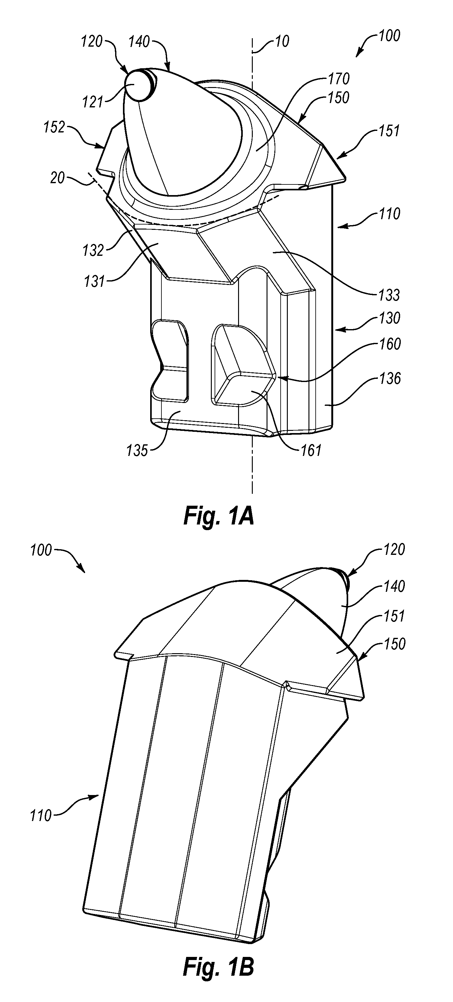
FIG. 1A is a front isometric view of a cutting tool assembly according to an embodiment;
FIG. 1B is a back isometric view of the cutting tool assembly of FIG. 1A;
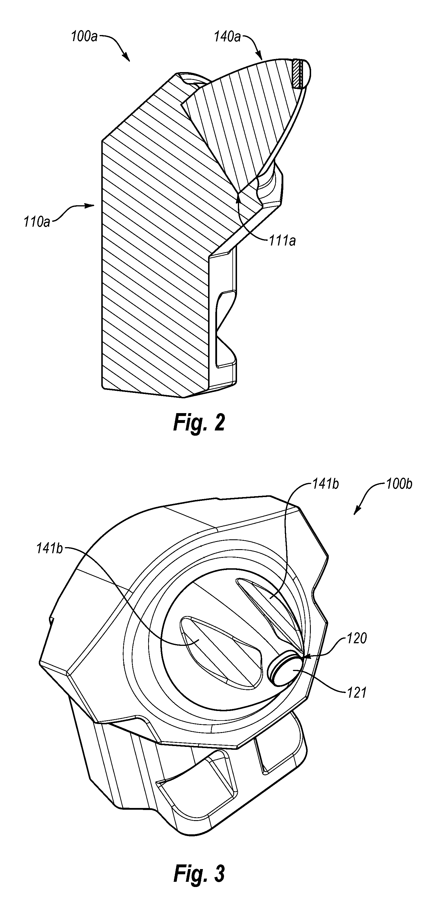
FIG. 2 is a cross-sectional view of the cutting tool assembly of FIG. 1A;
FIG. 3 is an isometric view of a cutting tool assembly according to an embodiment;
FIG. 4 is a partial isometric view of a cutting tool assembly according to another embodiment;
FIG. 5 is a partial isometric view of a cutting tool assembly according to yet another embodiment;
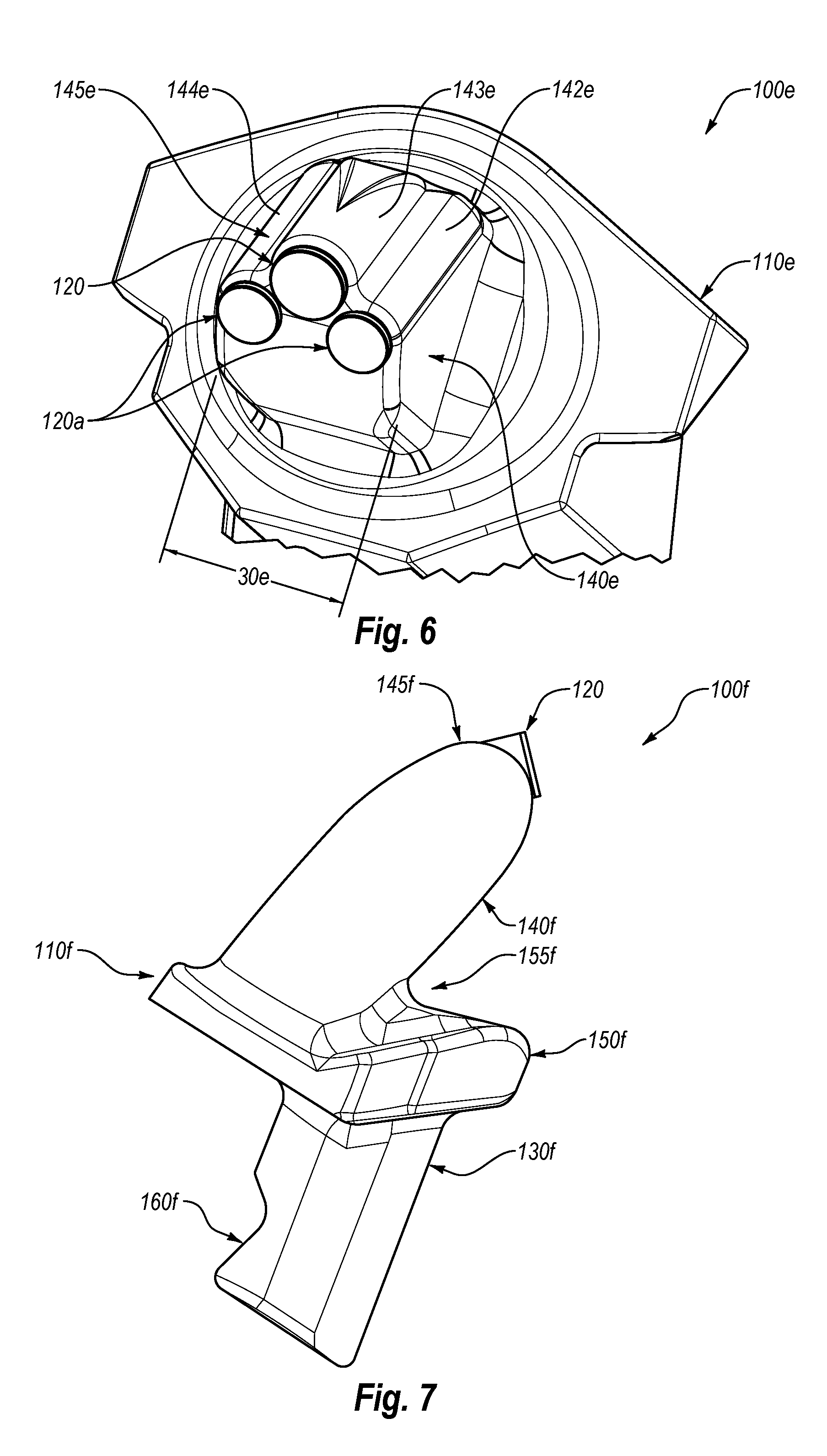
FIG. 6 is a partial isometric view of a cutting tool assembly according to still one other embodiment;
FIG. 7 is a side view of a cutting tool assembly according to an embodiment;
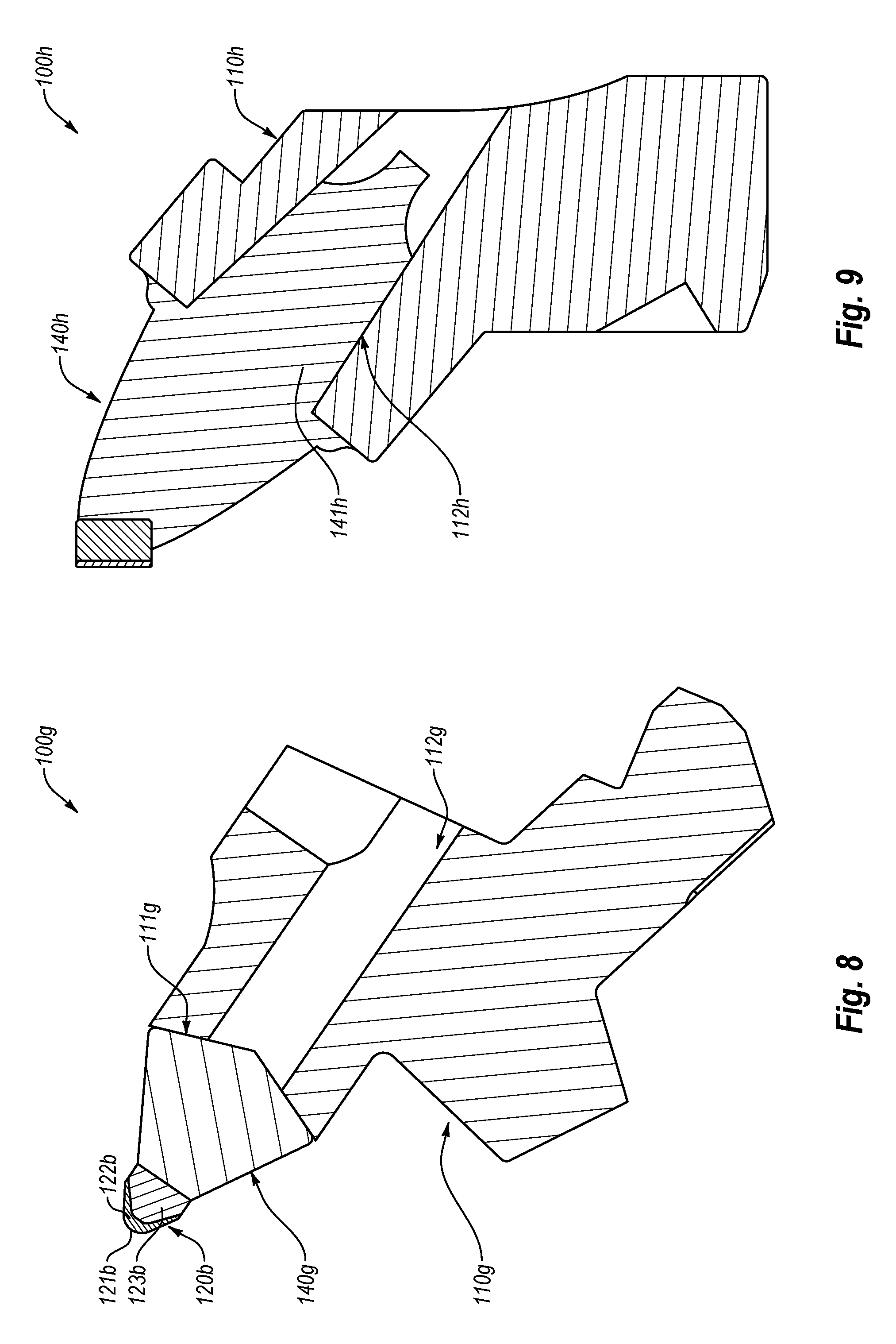
FIG. 8 is a cross-sectional view of a cutting tool assembly according to an embodiment;
FIG. 9 is a cross-sectional view of a cutting tool assembly according to another embodiment;
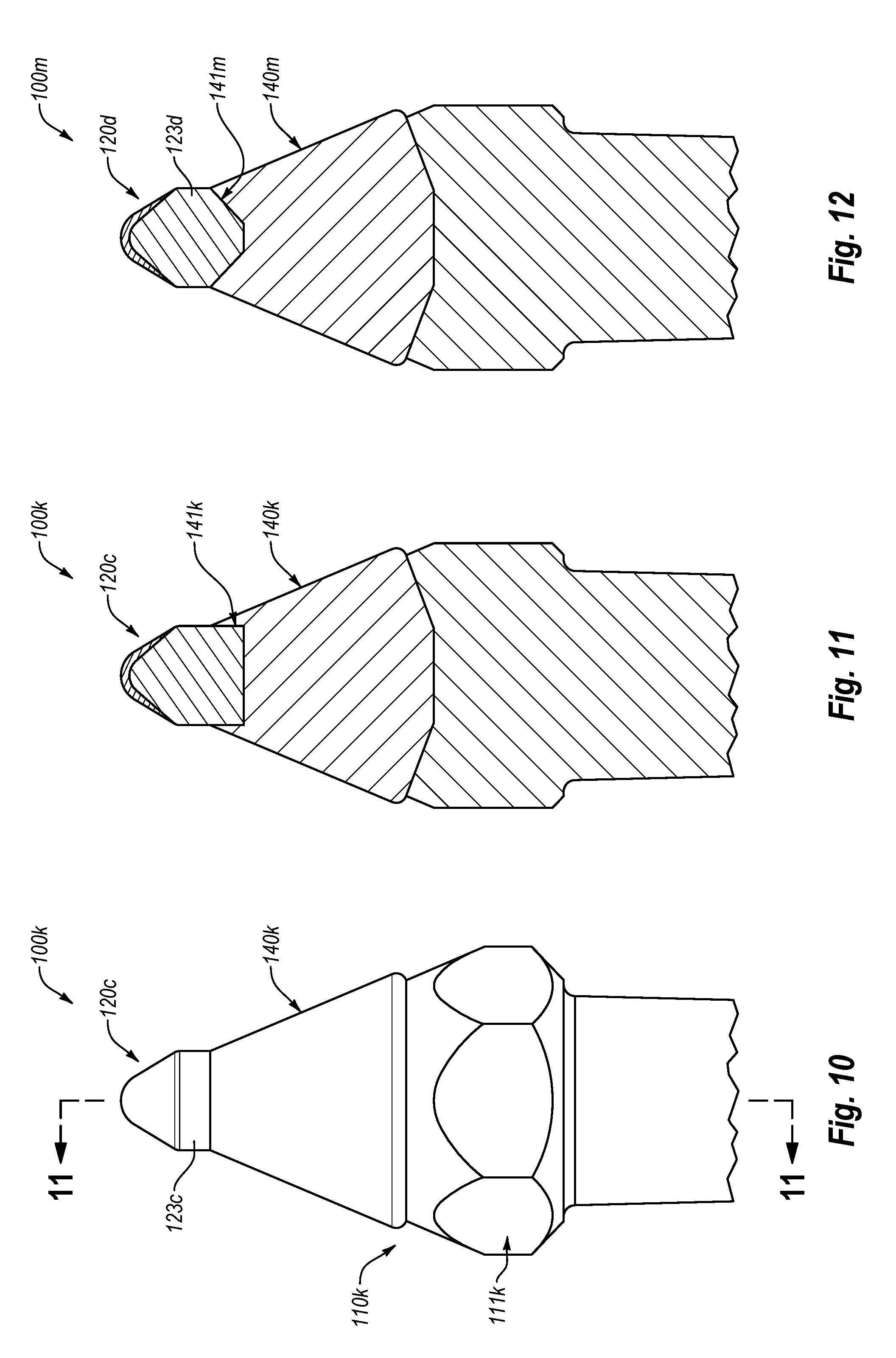
FIG. 10 is a partial side view of a cutting tool assembly according to an embodiment;
FIG. 11 is a partial cross-sectional view of the cutting tool assembly FIG. 10;
FIG. 12 is a partial cross-sectional view of a cutting tool assembly according to another embodiment;
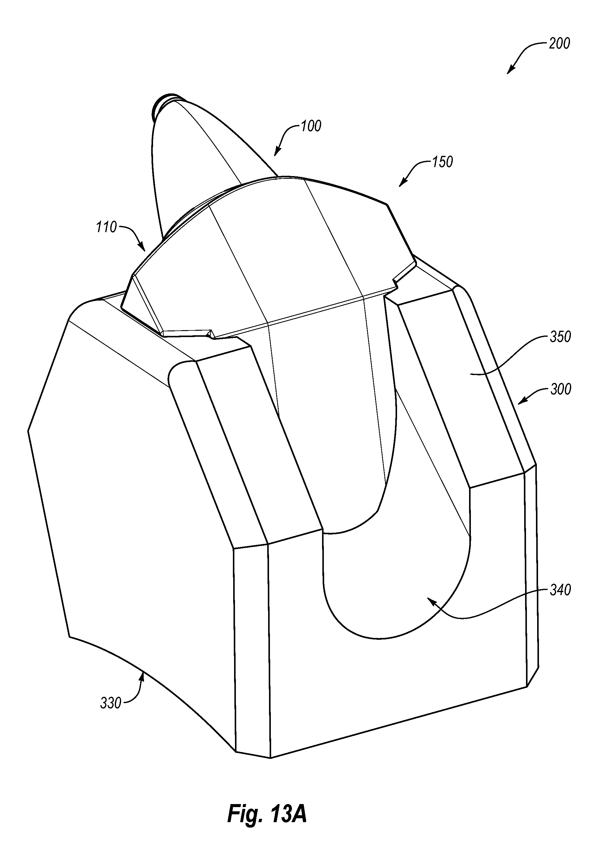
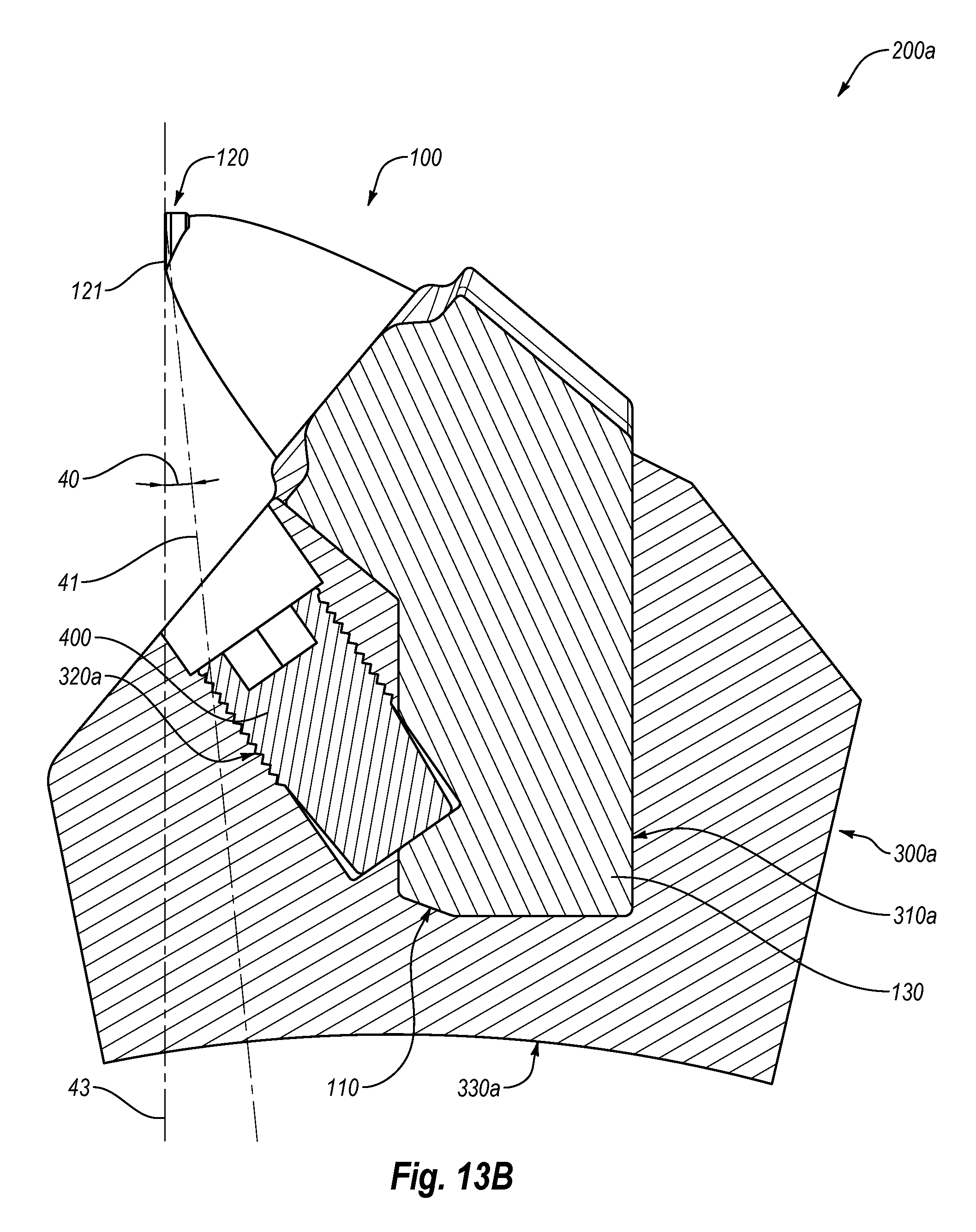
FIG. 13A is a back isometric view of a cutting tool mounting assembly according to an embodiment;
FIG. 13B is a cross-sectional view of the cutting tool mounting assembly of FIG. 13A;
FIG. 14 is side view of a cutting tool assembly according to an embodiment;
FIG. 15 is a partial cross-sectional view of a cutting tool mounting assembly according to an embodiment;
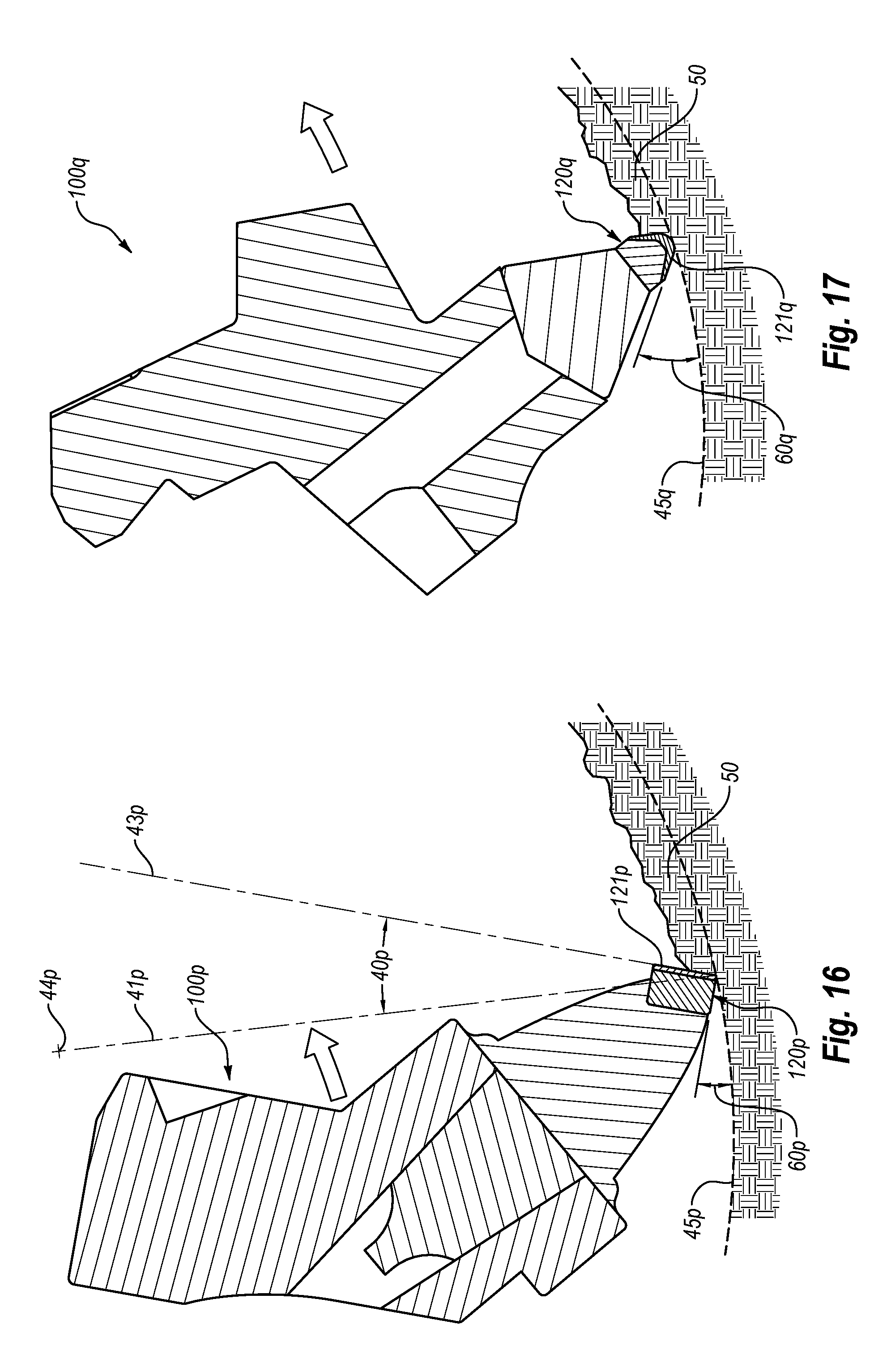
FIG. 16 is a schematic cross-sectional view of a cutting tool assembly in operation according to an embodiment;
FIG. 17 is a schematic cross-sectional view of a cutting tool assembly in operation according to another embodiment;
FIG. 18 is an isometric view of a rotary drum assembly according to an embodiment; and
FIG. 19 is a side view of a material-removing machine according to an embodiment.
DETAILED DESCRIPTION
Embodiments of the invention are directed to cutting tool assemblies, cutting tool mounting assemblies, material-removing machines that include cutting tool assemblies and/or cutting tool mounting assemblies, and methods of use and operation thereof. In some embodiments, the various assemblies described herein may be used in material-removing machines that may remove target material, such as a portion or a layer of a pavement. For example, a material-removing machine may include a rotary drum, and the cutting tool assemblies and/or the cutting tool mounting assembly may be mounted to or on the rotary drum. Furthermore, as the material-removing machine rotates the cutting tool assemblies together with the rotary drum, the cutting tool assemblies may engage and cut, grind, or otherwise fail the target material, which may be subsequently removed (e.g., by rotary drum assembly of the material-removing machine).
In an embodiment, the cutting tool assemblies may include one or more superhard working surfaces that may engage the target material. As used herein, "superhard material" includes materials exhibiting a hardness that is at least equal to the hardness of tungsten carbide (i.e., a portion of or the entire working surface may have a hardness that exceeds the hardness of tungsten carbide). In any of the embodiments disclosed herein, the cutting tool assemblies and the cutting elements may include one or more superhard materials, such as polycrystalline diamond, polycrystalline cubic boron nitride, silicon carbide, tungsten carbide, or any combination of the foregoing superhard materials. For example, a cutting element may include a substrate and a superhard material bonded to the substrate, as described in further detail below. The superhard material may form or define the working surface.
The cutting tool assemblies may include a support block. For example, the support block may be sized and configured to be removably secured to and/or within a base body of cutting tool mounting assembly, and the base body may be secured to a rotatable assembly (e.g., a rotary drum body of a rotary drum). In an embodiment, the support block may include an elongated mounting shank that may be at least partially positioned in a recess of base body and may be secured therein, thereby securing the cutting tool assembly to the base of the cutting tool mounting assembly. Moreover, a bolster body may be bonded to or integrated with the elongated mounting shank of the support block. The bolster body and the elongated mounting shank may be configured such that securing the elongated mounting shank in and/or to the base body to position and orient the bolster body at a predetermined angle relative to a radial line extending from a center of rotation of the rotary drum (e.g., when the base body is mounted to the rotary drum). For example, the bolster body may have a streamlined geometry to help reduce drag during cutting operations and, consequently, improve cutting efficiency.
In an embodiment, the working surface may be formed on or secured to the bolster body (e.g., the working surface may be formed on a cutting element that is secured to the bolster body). Generally, the bolster body may have any number of suitable shapes. In some embodiments, the bolster body may be shaped, sized, or otherwise configured in a manner that may reduce wear thereof during operation. Moreover, in one or more embodiments, the bolster body may be configured to protect or shield at least a portion of the cutting element, such as from erosion and/or wear, (e.g., in a manner that extends the useful life of the cutting element and/or extends useful life of the bond or attachment between the cutting element and the bolster body).
FIGS. 1A and 1B illustrate front and back isometric views, respectively, of a cutting tool assembly 100 according to an embodiment. For example, as shown in FIG. 1A, the cutting tool assembly 100 includes a support block 110 and a cutting element 120. More specifically, for example, the support block 110 may include an elongated mounting shank 130 and a bolster body 140 that may be secured to or integrated with the elongated mounting shank 130; the cutting element 120 may be secured to or integrated with the bolster body 140 (e.g., the cutting element 120 may be secured with fasteners, welding, brazing, press-fitting, etc., or combination of the foregoing). As described above, the support block 110 maybe sized, shaped, or otherwise configured to be secured at least partially within a base body that may be secured to a rotary drum of a material-removal machine.
As described below in more detail, the cutting element 120 may include a superhard working surface 121. In the illustrated embodiment, the superhard working surface 121 is generally planar. However, the superhard working surface 121 may have any suitable shape and configuration, which may vary from one embodiment to another (e.g., the superhard working surface 121 may be generally domed, generally pointed, or semi-spherical and/or may have a perimeter that may be circular, semi-circular, elliptical, square, or wedge-shaped). The superhard working surface 121 may be sized and configured to engage, cut, scrape, or otherwise cause the target material to fail. For example, the superhard working surface 121 may include a cutting edge that may define at least a portion of the perimeter of the superhard working surface 121. In an embodiment, the superhard working surface 121 may include the cutting edge that may facilitate entry or penetration of the cutting element 120 into the target material and subsequent failing and/or removal thereof.
In some embodiments, the superhard working surface 121 may include a chamfered periphery. In other words, a chamfer may extend from and about at least a portion of the superhard working surface 121 to a peripheral surface of the cutting element 120. As such, the chamfer may form two or more cutting edges (e.g., a cutting edge formed at the interface between the superhard working surface 121 and the chamfer and another cutting edge formed at the interface between the chamfer and the peripheral surface of the cutting element 120).
In some embodiments, the superhard working surface 121 may include superhard material. As used herein, "superhard material" includes a material exhibiting a hardness that is at least equal to the hardness of tungsten carbide (e.g., a portion or the entire working surface may have a hardness that exceeds the hardness of tungsten carbide). In any of the embodiments disclosed herein, the cutting assemblies and the cutting elements may include one or more superhard materials, such as polycrystalline diamond, polycrystalline cubic boron nitride, silicon carbide, tungsten carbide, or any combination of the foregoing superhard materials. For example, a cutting element may include a substrate and a superhard material bonded to the substrate, as described in further detail below.
In some embodiments, the superhard working surface 121 may be formed or defined by a superhard table that may be attached to a substrate. In an embodiment, the substrate may be attached to the bolster body 140. For example, the cutting element 120 (e.g., the substrate thereof) may be recessed in the bolster body 140, such that the bolster body 140 protects or shields the cutting element 120 from wear and/or erosion. Alternatively, the superhard table may be attached directly to the bolster body 140 (e.g., the bolster body 140 may include cemented carbide, and the superhard table that defines the superhard working surface 121 may be bonded directly to the bolster body). That is, the bolster body 140 may form the substrate (e.g., the bolster body 140 may include suitable material for bonding the superhard table thereto, such as tungsten carbide).
In an embodiment, the superhard table may comprise polycrystalline diamond and the substrate may comprise cobalt-cemented tungsten carbide. Furthermore, in any of the embodiments disclosed herein, the polycrystalline diamond table may be leached to at least partially remove or substantially completely remove a metal-solvent catalyst (e.g., cobalt, iron, nickel, or alloys thereof) that was used to initially sinter precursor diamond particles to form the polycrystalline diamond. In another embodiment, an infiltrant used to re-infiltrate a preformed leached polycrystalline diamond table may be leached or may otherwise have a metallic infiltrant removed to a selected depth from a working surface. Moreover, in any of the embodiments disclosed herein, the polycrystalline diamond may be un-leached and include a metal-solvent catalyst (e.g., cobalt, iron, nickel, or alloys thereof) that was used to initially sinter the precursor diamond particles that form the polycrystalline diamond and/or an infiltrant used to re-infiltrate a preformed leached polycrystalline diamond table. Examples of methods for fabricating the superhard tables and superhard materials and/or structures from which the superhard tables and elements may be made are disclosed in U.S. Pat. Nos. 7,866,418; 7,998,573; 8,034,136; and 8,236,074; the disclosure of each of the foregoing patents is incorporated herein, in its entirety, by this reference.
The diamond particles that may be used to fabricate the superhard table in a high-pressure/high-temperature process ("HPHT)" may exhibit a larger size and at least one relatively smaller size. As used herein, the phrases "relatively larger" and "relatively smaller" refer to particle sizes (by any suitable method) that differ by at least a factor of two (e.g., 30 .mu.m and 15 .mu.m). According to various embodiments, the diamond particles may include a portion exhibiting a relatively larger size (e.g., 70 .mu.m, 60 .mu.m, 50 .mu.m, 40 .mu.m, 30 .mu.m, 20 .mu.m, 16 .mu.m, 15 .mu.m, 12 .mu.m, 10 .mu.m, 8 .mu.m) and another portion exhibiting at least one relatively smaller size (e.g., 15 .mu.m, 12 .mu.m, 10 .mu.m, 8 .mu.m, 6 .mu.m, 5 .mu.m, 4 .mu.m, 3 .mu.m, 2 .mu.m, 1 .mu.m, 0.5 .mu.m, less than 0.5 .mu.m, 0.1 .mu.m, less than 0.1 .mu.m). In an embodiment, the diamond particles may include a portion exhibiting a relatively larger size between about 10 .mu.m and about 40 .mu.m and another portion exhibiting a relatively smaller size between about 1 .mu.m and 4 .mu.m. In another embodiment, the diamond particles may include a portion exhibiting the relatively larger size between about 15 .mu.m and about 50 .mu.m and another portion exhibiting the relatively smaller size between about 5 .mu.m and about 15 .mu.m. In another embodiment, the relatively larger size diamond particles may have a ratio to the relatively smaller size diamond particles of at least 1.5. In some embodiments, the diamond particles may comprise three or more different sizes (e.g., one relatively larger size and two or more relatively smaller sizes), without limitation. The resulting polycrystalline diamond formed from HPHT sintering the aforementioned diamond particles may also exhibit the same or similar diamond grain size distributions and/or sizes as the aforementioned diamond particle distributions and particle sizes. Additionally, in any of the embodiments disclosed herein, the superhard cutting elements may be free-standing (e.g., substrateless) and/or formed from a polycrystalline diamond body that is at least partially or fully leached to remove a metal-solvent catalyst initially used to sinter the polycrystalline diamond body.
As noted above, the superhard table may be bonded to the substrate. For example, the superhard table comprising polycrystalline diamond may be at least partially leached and bonded to the substrate with an infiltrant exhibiting a selected viscosity, as described in U.S. patent application Ser. No. 13/275,372, entitled "Polycrystalline Diamond Compacts, Related Products, And Methods Of Manufacture," the entire disclosure of which is incorporated herein by this reference. In an embodiment, an at least partially leached polycrystalline diamond table may be fabricated by subjecting a plurality of diamond particles (e.g., diamond particles having an average particle size between 0.5 .mu.m to about 150 .mu.m) to an HPHT sintering process in the presence of a catalyst, such as cobalt, nickel, iron, or an alloy of any of the preceding metals to facilitate intergrowth between the diamond particles and form a polycrystalline diamond table comprising bonded diamond grains defining interstitial regions having the catalyst disposed within at least a portion of the interstitial regions. The as-sintered polycrystalline diamond table may be leached by immersion in or exposure to an acid or subjected to another suitable process to remove at least a portion of the catalyst from the interstitial regions of the polycrystalline diamond table, as described above. The at least partially leached polycrystalline diamond table includes a plurality of interstitial regions that were previously occupied by a catalyst and form a network of at least partially interconnected pores. In an embodiment, the sintered diamond grains of the at least partially leached polycrystalline diamond table may exhibit an average grain size of about 20 .mu.m or less. Subsequent to leaching the polycrystalline diamond table, the at least partially leached polycrystalline diamond table may be bonded to a substrate in an HPHT process via an infiltrant with a selected viscosity. For example, an infiltrant may be selected that exhibits a viscosity that is less than a viscosity typically exhibited by a cobalt cementing constituent of typical cobalt-cemented tungsten carbide substrates (e.g., 8% cobalt-cemented tungsten carbide to 13% cobalt-cemented tungsten carbide).
Additionally or alternatively, the superhard table may be a polycrystalline diamond table that has a thermally-stable region, having at least one low-carbon-solubility material disposed interstitially between bonded diamond grains thereof, as further described in U.S. patent application Ser. No. 13/027,954, entitled "Polycrystalline Diamond Compact Including A Polycrystalline Diamond Table With A Thermally-Stable Region Having At Least One Low-Carbon-Solubility Material And Applications Therefor," the entire disclosure of which is incorporated herein by this reference. The low-carbon-solubility material may exhibit a melting temperature of about 1300.degree. C. or less and a bulk modulus at 20.degree. C. of less than about 150 GPa. The low-carbon-solubility, in combination with the high diamond-to-diamond bond density of the diamond grains, may enable the low-carbon-solubility material to be extruded between the diamond grains and out of the polycrystalline diamond table before causing the polycrystalline diamond table to fail during operations.
In some embodiments, the polycrystalline diamond, which may form the superhard table, may include bonded-together diamond grains having aluminum carbide disposed interstitially between the bonded-together diamond grains, as further described in U.S. patent application Ser. No. 13/100,388, entitled "Polycrystalline Diamond Compact Including A Polycrystalline Diamond Table Containing Aluminum Carbide Therein And Applications Therefor," the entire disclosure of which is incorporated herein by this reference.
In some embodiments, one or more portions and/or surfaces of the support block 110 may be configured to be pressed or forced to at least partially contact corresponding portions and/or surfaces of the base body. For example, pressing one or more surfaces of the support block 110 against corresponding one or more surfaces of the base body may prevent or limit movement of the support block 110 in one or more directions or orientations relative to the base body (e.g., during operation of the cutting tool assembly 100). In the illustrated embodiment, the elongated mounting shank 130 includes an angled surface 131 that may at least partially contact a corresponding angled surface and the base body. In particular, for example, the surface 131 may form an obtuse angle with a vertical axis 10 of the cutting tool assembly 100. For example, the vertical axis 10 may be generally parallel to a vertical portion of the elongated mounting shank 130 (e.g., parallel to peripheral surfaces 135, 136 of the elongated mounting shank 130).
Furthermore, the support block 110 may include multiple angled surfaces that may be oriented at various angles relative to the vertical axis 10. For example, the surface 131 may extend between angled surfaces 132, 133, which may be positioned along each side of surface 131 (e.g., the surfaces 132 and/or 133 may be at a different angle relative to the vertical axis than surface 131). In an embodiment, the surface 131 may be generally planar. Similarly, the surfaces 132 and/or 133 may be generally planar. As shown in the illustrated embodiment, the surfaces 131, 132, 133 may be arranged along a generally arcuate path, such as along an imaginary arcuate path 20 (e.g., the surfaces 131, 132, 133 may be generally tangent to the arcuate path 20). For example, as described below in more detail, when the elongated mounting shank 130 is positioned in the base body, and the surfaces 131, 132, 133 may abut or press against corresponding surfaces of the base body, the surfaces 131, 132, 133 may prevent or limit movement of the cutting tool assembly 100 relative to the base body (e.g., in directions generally outward from the surfaces 131, 132, 133) and may prevent or limit pivoting or twisting of the cutting tool assembly 100 relative to the base body (e.g., about the vertical axis 10).
Generally, the vertical portion of the elongated mounting shank 130 may have any suitable peripheral shape that may be defined by one or more peripheral surfaces and may vary from one embodiment to the next. In the illustrated embodiment, the peripheral surfaces defining the vertical portion of the elongated mounting shank 130 may include one or more planar surfaces, such as surfaces 135 and 136 (e.g., surface 135 may be oriented at approximately 90.degree. angle relative to surface 136, and surfaces 135, 136 may be generally parallel to the vertical axis 10). For example, planar surfaces defining the vertical portion of the elongated mounting shank 130 may correspond to and/or abut or at least partially contact corresponding surfaces of the base body in a manner that prevents or limits rotation or pivoting of the cutting tool assembly 100 about the vertical axis 10.
As described above, the bolster body 140 may be secured (e.g., by welding, brazing, soldering, laser fusing, press-fitting, mechanically attaching, combinations of the foregoing, etc.) to the support block 110 (e.g., to the elongated mounting shank 130). In some embodiments, the bolster body 140 may be oriented at a non-parallel and/or non-perpendicular angle relative to the elongated mounting shank 130. For example, the bolster body 140 and the elongated mounting shank 130 may form or define an obtuse angle therebetween.
In some embodiments, the bolster body 140 may be bonded to the elongated mounting shank 130 (e.g., the bolster body 140 may be bonded to the elongated mounting shank 130 by brazing, welding, press-fitting, mechanically attaching, combinations of the foregoing, etc.). Alternatively, the elongated mounting shank 130 and bolster body 140 may be integral or integrated together (e.g., the bolster body 140 and elongated mounting shank 130 may be formed or fabricated from a single piece of material). In some embodiments, the bolster body 140 and elongated mounting shank 130 may include different materials from each other. For example, the bolster body 140 may include a material that is stronger (e.g., exhibiting a higher yield strength) and/or more abrasion resistant than the material of the elongated mounting shank 130). In at least one embodiment, the bolster body 140 may include a material such as carbide and/or cemented carbide (e.g., the bolster body 140 may include any number of carbide materials and/or cementing alloys, which may be similar to or the same as the carbides described herein in connection with the substrate of the cutting element 120) and the elongated mounting shank 130 may include steel, and the bolster body 140 may be brazed to the elongated mounting shank 130. Additionally or alternatively, the bolster body 140 may include any suitable steel (e.g., carbon steel, stainless steel, or tool steel), which may be heat treated to a suitable hardness. For example, a steel bolster body 140 may be welded to the elongated mounting shank 130.
The support block 110 may include an upper portion 150, and the bolster body 140 may be secured to or integrated with the upper portion 150 and may extend outward therefrom. In some embodiments, the upper portion 150 may have a greater peripheral size (e.g., may be wider and/or longer) that the elongated mounting shank 130. For example, the upper portion 150 may include one or more shoulder portions or shoulders, such as shoulders 151, 152 that extend beyond the elongated mounting shank 130 (e.g., one or more surfaces of the shoulders 151, 152 may extend beyond one or more surfaces of the elongated mounting shank 130 and may optionally extend generally perpendicularly therefrom). For example, the shoulders 151 and/or 152 may at least partially contact one or more corresponding portions or surfaces of the base block (e.g., the shoulders 151 and/or 152 may vertically position the cutting tool assembly 100 relative to the base block). Under some operating conditions, as the cutting element 120 engages and/or enters the target material, the cutting tool assembly 100 may experience one or more forces thereon, which may urge movement of the cutting tool assembly 100 relative to the base body.
In some embodiments, however, the cutting tool assembly 100 may be fixedly secured (e.g., by metallurgical attachment, such as brazing, soldering, welding, etc., by mechanical attachment (e.g., bolts and/or clamps), such as by press-fitting, fastening, etc., or combinations of the foregoing, etc.) to the base body in a manner that limits or prevents movement that may otherwise result during operation of the cutting tool assembly 100. For example, the shoulders 151 and/or 152 may at least partially counteract or oppose the forces experience by the cutting tool assembly 100 during operation (e.g., as the shoulders 151 and/or 152 press against corresponding portions and/or surfaces of the base body). Additionally or alternatively, as mentioned above, the shape and/or size of the elongated mounting shank 130 (e.g., the shape and/or size of the vertical portion of the elongated mounting shank 130, the surfaces 131, 132, 133 of the elongated mounting shank 130, etc.) may prevent or limit movement of the cutting tool assembly 100 relative to the base body (e.g., from the forces experienced by the cutting tool assembly 100 during operation).
In some embodiments, the elongated mounting shank 130 may be secured to and/or positioned at least partially within the corresponding recess in the base body by one or more fasteners. For example, the elongated mounting shank 130 may include one or more locations that may accept or facilitate one or more corresponding fasteners that may secure or fasten the cutting tool assembly 100 to the base body. In the illustrated embodiment, the elongated mounting shank 130 includes fastener recesses 160. In particular, for example, the recesses 160 may include at least one surface against which a fastener may press or contact, thereby positioning the elongated mounting shank 130 at least partially into the recess in the base body. In an embodiment, the recesses 160 may include corresponding surfaces 161 (e.g., the surfaces 161 may be generally perpendicular to the surface 131). In any event, contact between a leading face of a fastener and one or more surfaces 161 of the recesses 160 may retain the elongated mounting shank 130 in the base body, thereby securing the cutting tool assembly at least partially within and/or to the base body in a manner that prevents or limits movement of the cutting tool assembly 100 relative to the base body during operation.
As described below in more detail, the bolster body 140 may be generally shaped to reduce drag as the cutting tool assembly 100, together with the bolster body 140, advances into the target material. In an embodiment, the bolster body 140 may be shaped such that the failed material may move away from the cutting element 120. For example, the bolster body 140 may have a generally tapered shape (e.g., a generally conical shape or frusto-conical shape). Moreover, the elongated mounting shank 130 may include a transition region 170, which may provide or form a transition between the bolster body 140 and the upper portion 150. For example, the transition region may extend between the bolster body 140 and an upper surface of the upper portion 150.
In some embodiments, the transition region 170 may be shaped, sized, and otherwise configured to guide or direct the flow or movement of the failed material past the bolster body 140 and along or over the upper portion 150 of the support block 110. For example, the transition region 170 may be generally tapered, such that the smaller portion of the taper is near the bolster body 140 and the larger portion of the taper is near the upper portion 150. In at least one embodiment, at least a portion of the upper portion 150 may be shaped to deflect or channel the failed material away from the support block 110 during operation. As shown in FIG. 1B, for example, an upper surface 151 of the upper portion 150 may be generally arcuate or may otherwise slant downward and away from an uppermost point of the upper portion 150.
In an embodiment, the support block 110 may be generally solid or monolithic. Alternatively, the support block 110 may include one or more cutouts or recesses, such as in a back side thereof (e.g., in a side facing away from the direction of movement or cut of the cutting tool assembly 100 during operation). For example, the recess(es) may facilitate or allow channeling movement or flow of failed material away from the cutting tool assembly 100.
As mentioned above, the bolster body 140 may be incorporated with or bonded to the support block 110. FIG. 2 illustrates a cutting tool assembly 100a that includes a bolster body 140a bonded to a support block 110a, according to an embodiment. Except as otherwise described herein, the cutting tool assembly 100a and its materials, features, elements, or components may be similar to or the same as cutting tool assembly 100 (FIGS. 1A-1B) and its respective materials, features, elements and components. For example, the support block 110a may include a cutting element 120 that may be similar to or the same as the cutting element 120 of the cutting tool assembly 100 (FIGS. 1A-1B).
In an embodiment, the support block 110a may include a recess 111a for locating the bolster body 140a relative to the support block 110a. In some embodiments, the recess 111a may have a generally circular perimeter (e.g., the recess 111a may be cylindrical). Alternatively, the perimeter of recess 111a may have at least partially non-circular shape, which may facilitate orienting the bolster body 140a relative to the support block 110a. In any event, in at least one embodiment, the bolster body 140a may be positioned in the recess 111a and may be bonded (e.g., brazed, welded, etc.) to at least a portion of a wall defining the recess 111a and/or to the support block 110a.
As described above, the bolster body may be generally shaped to reduce or minimize or limit drag during operation of the cutting tool assembly, as the cutting tool assembly moves through the target material. In some embodiments, the bolster body may include one or more drag-reduction features that may reduce drag of the bolster body (e.g., as compared with a bolster body without such features), which may extend the useful life of the cutting tool assembly. FIG. 3 illustrates an isometric view of a cutting tool assembly 100b that has a bolster body 140b with drag-reduction features, according to an embodiment. Except as otherwise described herein, the cutting tool assembly 100b and its materials, features, elements, or components may be similar to or the same as any of the cutting tool assemblies cutting tool assemblies 100, 100a (FIGS. 1A-2) and their respective materials, features, elements and components. For example, the cutting tool assembly 100b may include a support block 110b and a bolster body 140b bonded together or integrated with each other, and the support block 110b may be similar to or the same as the support block 110 (FIGS. 1A-1B). It should be appreciated that, as noted above, the same or similar reference numbers (e.g., the same base reference numbers with different letter modifiers, such as support blocks 110 and 110a (FIGS. 1A-2), may comprise the same or similar material and/or may include one, some, or all of the same features and/or elements.
In an embodiment, the bolster body 140b may include notches 141b that may extend from a forward facing portion of the bolster body 140b (e.g., portion facing generally in the same direction as the superhard working surface 121 of the cutting element 120) and to the backward facing portion of the bolster body 140b (e.g., portion facing away from the superhard working surface 121 of the cutting element 120). As described above, during operation, as the bolster body 140b of the cutting tool assembly 100b enters the target material, the cutting element 120 may fail the target material. For example, at least some of failed material may flow or move away from the superhard working surface 121 of the cutting element 120 and through one or more notches 141b. In some embodiments, the notches 141b may facilitate movement of the failed material away from the superhard working surface 121, thereby extending useful life thereof. Furthermore, for example, the bolster body 140b that includes the notches 141b may be generate less drag through the target material and thereby may require less energy during operation thereof (as compared with a bolster body that does not include the notches).
In some embodiments, the bolster body may have a generally narrow profile, which may facilitate reduced drag as the cutting tool assembly moves through the target material (as compared with a cutting tool that includes a relatively wider bolster body). FIG. 4 illustrates an isometric view of a cutting tool assembly 100c that includes a narrow bolster body 140c, according to an embodiment. Except as otherwise described herein, the cutting tool assembly 100c and its materials, features, elements, or components may be similar to or the same as any of the cutting tool assemblies 100, 100a, 100b (FIGS. 1A-3) and their respective materials, features, elements and components. For example, the cutting tool assembly 100c may include a support block 110c and a bolster body 140c bonded together or integrated with each other, and the support block 110c may be similar to or the same as the support block 110 (FIGS. 1A-1B).
In an embodiment, the bolster body 140c may be generally narrow to reduce drag thereof in the target material (e.g., as compared with wider bolster bodies). More specifically, for example, the cutting element 120 may be mounted to the bolster body 140c, and the bolster body 140c may have a first dimension, such as width 30c, that may be similar to or the same as a dimensions of the cutting element 120, such as the width or diameter of the cutting element 120 (e.g., as measure along an imaginary line that is generally perpendicular to the direction of cut during operation of the cutting tool assembly 100c). For example, the width 30c of the bolster body 140c may be smaller than a length 35c thereof. In an embodiment, the width 30c of the bolster body 140c may be less than 2 times the diameter of the cutting element 120 or less than 3.times. the diameter of the cutting element 120 (e.g., the width 30c may be a multiple of the diameter of the cutting element 120, which may be in one or more of the following ranges: about 1.01-1.1 times the diameter of the cutting element 120; about 1.09-1.3 times the diameter of the cutting element 120; about 1.1-1.5 times the diameter of the cutting element 120; or about 1.4-1.9 times the diameter of the cutting element 120). Hence, in an embodiment, the width 30c of the bolster body 140c may be suitably narrow (e.g., relative to the support block 110), such as to reduce resistance or contact between the bolster body 140c and the target material engaged by the cutting tool assembly 100c.
Furthermore, in some embodiments, the bolster body 140c may include one or more generally planar surfaces, such as surfaces 142c, 143c. In an embodiments, the width 30c of the bolster body 140c may be defined by generally planar surfaces, such as the surface 142c and a surface opposite thereto, which may be similar to or the same as the surface 142c. In at least one embodiment, the leading face of the bolster body 140c (e.g., a face of the bolster body 140c that generally faces in the direction of cut or movement of the cutting tool assembly 100c during operation) and/or the trailing face thereof (e.g., a face of the bolster body 140c that generally faces away from the direction of cut or movement of the cutting tool assembly 100c during operation) may be defined by one or more generally planar surfaces. For example, the trailing face of the bolster body 140c may be at least partially defined by the surface 143c.
Any of the cutting tool assemblies described herein may include any number of cutting elements, which may vary from one embodiment to the next. FIG. 5 illustrates a cutting tool assembly 100d that includes two cutting element 120a, according to an embodiment. Except as otherwise described herein, the cutting tool assembly 100d and its materials, features, elements, or components may be similar to or the same as any of the cutting tool assemblies 100, 100a, 100b, 100c (FIGS. 1A-4) and their respective materials, features, elements and components. For example, the cutting tool assembly 100d may include a support block 110d and a bolster body 140d bonded together or integrated with each other, and the support block 110d may be similar to or the same as the support block 110 (FIGS. 1A-1B).
In an embodiment, the cutting elements 120a may be positioned near each other and/or may abut each other. For example, the cutting elements 120a may be aligned generally along a width 30d of the bolster body 140d. Alternatively or additionally, the cutting elements 120a may be positioned near each other and at a predetermined height (e.g., as measured downward from an uppermost portion of the bolster body 140d.
As described above, the bolster body 140d may include one or more notches that (for example) may facilitate movement or flow of failed material away from superhard working surfaces 121a of the cutting elements 120a. In some embodiments, the bolster body 140d may include a notch 141d that may extend between the cutting elements 120a. For example, at least some of the failed material may move away from the superhard working surface 121a of the cutting elements 120a and into the notch 141d of the bolster body 140d, which may extend useful life of the cutting elements 120a.
FIG. 6 illustrates an isometric view of a cutting tool assembly 100e that includes three cutting elements, according to an embodiment. Except as otherwise described herein, the cutting tool assembly 100e and its materials, features, elements, or components may be similar to or the same as any of the cutting tool assemblies 100, 100a, 100b, 100c, 100d (FIGS. 1A-5) and their respective materials, features, elements and components. For example, the cutting tool assembly 100e may include a support block 110e and a bolster body 140e bonded together or integrated with each other, and the support block 110e may be similar to or the same as the support block 110 (FIGS. 1A-1B).
In an embodiment, the cutting tool assembly 100e may include two cutting elements 120a and one cutting element 120 (e.g., the cutting element 120 may be positioned at least partially between the cutting elements 120a). For example, the corresponding ones of the cutting elements 120a may and the cutting element 120 may be positioned at different apexes of an imaginary triangle (e.g., the imaginary triangle may be an equilateral triangle with the base thereof oriented generally parallel to a width 30e of the bolster body 140e). In some embodiments, the cutting element 120 may be positioned at or near an upper apex and near an uppermost portion of the bolster body 140, and the cutting elements 120a may be positioned at or near lower apexes of the imaginary triangle and along a base thereof.
The bolster body 140e may be generally sized, shaped, and otherwise configured to accommodate the cutting elements 120, 120a at suitable positions or locations. For example, the bolster body 140e may have an upper portion 145e supporting the cutting elements 120, 120a, such that the upper portion 145e is at least in part defined by rounded surfaces 142e, 143e, 144e, which may generally follow the contour of corresponding ones of the cutting elements 120a, 120. In some embodiments, a bolster body 140e may have a reduced drag through the target material (e.g., as compared with the bolster body that includes more material between the outer surface thereof and the cutting elements 120a and/or 120).
As described above, the bolster body may have any number of suitable shapes and/or sizes and may be integrated with the support block. FIG. 7 illustrates a side view of a cutting tool assembly 100f according to an embodiment. Except as otherwise described herein, the cutting tool assembly 100f and its materials, features, elements, or components may be similar to or the same as any of the cutting tool assemblies 100, 100a, 100b, 100c, 100d, 100e (FIGS. 1A-6) and their respective materials, features, elements and components. For example, as mentioned above, the cutting tool assembly 100f may include a support block 110f and bolster body 140f incorporated together (e.g., the support block 110f and the bolster body 140f may be integrally formed, such as fabricated from a single piece of material).
The support block 110f may include an elongated mounting shank 130f at least portion of which may be inserted into and/or secured to a base body (e.g., the elongated mounting shank 130f may include at least one recess 160f that may accept a portion of a fastener that may contact and/or restrict movement of the elongated mounting shank 130f, thereby securing the elongated mounting shank 130f in a recess of the base body). As described above, the support block 110f may include a upper portion 150f that may be attached to or integrated with the elongated mounting shank 130f (e.g., the upper portion 150f may facilitate positioning and/or securing of the support block 110f relative to the base body). Moreover, the bolster body 140f may extend from and/or may be integrated with the upper portion 150f.
In an embodiment, the bolster body 140f may have a generally cylindrical shape and a rounded upper portion 145f (e.g., a cutting element 120 may be attached to the bolster body 140f at or near the upper portion 145f thereof). In an embodiment, the cutting tool assembly 100s may include a transition region 155f (e.g., bend, notch, fillet, or chamfer) between the bolster body 140f and the upper portion 150f. For example, the transition region 155f may facilitate flow or movement failed material away from a leading portion of the cutting tool assembly 100f (e.g., away from a portion of the cutting tool assembly 100f that faces toward the cutting direction of the cutting tool assembly 100f during operation).
As mentioned above, the bolster body may be bonded to the support block of the cutting tool assembly. FIG. 8 illustrates a cross-sectional view of a cutting tool assembly 100g that includes a bolster body 140g bonded to a support block 110g, according to an embodiment. For example, the bolster body 140g may be brazed, welded, or otherwise metallurgically bonded to the support block 110g (e.g., along interface surface 111g). Except as otherwise described herein, the cutting tool assembly 100g and its materials, features, elements, or components may be similar to or the same as any of the cutting tool assemblies 100, 100a, 100b, 100c, 100d, 100e, 100f (FIGS. 1A-7) and their respective materials, features, elements and components. For example, as mentioned above, the cutting tool assembly 100g may include a support block 110g and bolster body 140g bonded together. The support block 110g may be similar to the any of the support blocks 110, 110a, 110b, 110c, 110d, 110e, or 110f (FIGS. 1A-7), as discussed above. Moreover, the bolster body 140g may be similar to any of bolster bodies 140a, 140b, 140c, 140d, 140e, or 140f (FIGS. 1A-7). It should be also appreciated that, while any of the bolster bodies described herein, such as the bolster body 140g, may include or comprise hard (e.g., superhard) or hardened material, additionally or alternatively, any of the bolster bodies may include coating, hardfacing, protective or wear plate, combinations thereof, etc. Also, the bolster bodies, the support block, and wear-resistant shields (e.g., a protective coating, hardfacing, or protective or wear plate) may have one or more of any number of suitable shapes, sizes, or materials, such as described in more detail in U.S. Patent Application No. 62/030,525; Ser. No. 14/266,437; and Ser. No. 14/275,574, the disclosure of each of the foregoing applications is incorporated herein, in its entirety, by this reference.
In some embodiments, the bolster body 140g may be bonded to the support block 110g along an angled or interface surface 111g. For example, the interface surface 111g may position and/or orient the bolster body 140g relative to the support block 110g at a predetermined position and orientation. In an embodiment, the support block 110g may include an opening or recess 112g. For example, the recess 112g may facilitate securing the bolster body 140g to the support block 110g with a fastener.
Also, as mentioned above, the particular shape and/or size of cutting element(s) included in the cutting tool assembly may vary from one environment to the next. In the illustrated embodiment, the cutting tool assembly 100g includes a generally convex cutting element 120b (e.g., at least partially domed, pointed, ovoid, conical, or rounded). In particular, the cutting element 120b may include a generally convex superhard working surface 121b, which may be defined by a superhard table 122b bonded to a substrate 123b. Moreover, the cutting element 120b may be bonded to and may extend beyond the bolster body 140g in a manner that facilitates engagement of the superhard working surface 121b with the target material during operation of the cutting tool assembly 100g.
Alternatively or additionally, a bolster body may be mechanically secured to support block (e.g., with fastener(s), press-fitting, fitted at a locking angle, etc.). FIG. 9 illustrates a cross-sectional view of a cutting tool assembly 100h that includes a bolster body 140h mechanically secured to the support block 110h, according to an embodiment. Except as otherwise described herein, the cutting tool assembly 100h and its materials, features, elements, or components may be similar to or the same as any of the cutting tool assemblies 100, 100a, 100b, 100c, 100d, 100e, 100f, 100g (FIGS. 1A-8) and their respective materials, features, elements and components. For example, as mentioned above, the cutting tool assembly 100h may include a support block 110h and bolster body 140h secured together, and the support block 110h may be similar to or the same as any of the support blocks 110, 100a, 100b, 110c, 110d, 110e, 110f, or 110g (FIGS. 1A-8), as described above.
In the illustrated embodiment, the support block 110h includes a recess 112h, and the bolster body 140h includes a shank 141h that may fit into the recess 112h and may be secured therein, thereby securing the bolster body 140h to the support block 110h. For example, the recess 112h may have a tapered configuration, and the shank 141h may have a generally corresponding or complementary taper, which may secure or lock the shank 141h in the recess 112h (e.g., the taper of the recess 112h and 114h may have a locking angle and/or may be a machine taper, such as Morse taper). Under some operating conditions, the bolster body 140h may be detached and/or removed from the support block 110h (e.g., for servicing and/or replacement). For example, the recess 112h may extend through the support block 110h, such that the shank 141h may be accessed from a back side of the support block 110h (e.g., access from the backside of the support block 110h may facilitate forcing the shank 141h out of the recess 112h). Moreover, in an embodiment, the shank 141h may be integrated with the bolster body 140h. In an embodiment, the shank 141h may be attached or secured to the bolster body 140h (e.g., the shank may be welded, brazed, soldered, or otherwise metallurgically attached to the bolster body 140h and/or may be fastened to the bolster body 140h).
The particular configuration of the cutting element may vary from one embodiment to the next. FIG. 10 is a partial side view of a cutting tool assembly 100k that includes a generally convex cutting element 120c, according to an embodiment. Except as otherwise described herein, the cutting tool assembly 100k and its materials, features, elements, or components may be similar to or the same as any of the cutting tool assemblies 100, 100a, 100b, 100c, 100d, 100e, 100f, 100g, 100h (FIGS. 1A-9) and their respective materials, features, elements and components.
In at least one embodiment, the cutting tool assembly 100k may be fastened to the base body. For example, a portion of a support block 110k may include one or more features that may accommodate a tool for fastening the support block to the base body (e.g., a wrench, etc.). In an embodiment, a lower portion 111k of the support block 110k may be configured to accept a wrench (e.g., the lower portion 111k of the support block 110k may have one or more flats, may have a generally hexagonal or square shape, etc.).
In at least one embodiment the cutting element 120c may be bonded to a bolster body 140k of the cutting tool assembly 100k. In some embodiments, a substrate 123c of the cutting element 120c may be at least partially exposed out of and/or extend beyond the bolster body 140k of the cutting tool assembly 100k. As shown in FIG. 11, for example, the bolster body 140k may include a pocket or recess 141k that may accommodate the cutting element 120c (e.g., the substrate 123c of the cutting element 120c). As described above, the cutting element 120c may be brazed, press-fit, fastened, or otherwise secured to the bolster body 140k. For example, the recess 141k may be sized and shaped in a manner that facilitates brazing, press-fitting, or otherwise securing the cutting element 120c to the bolster body 140k (e.g., the recess 141k may be generally cylindrical).
Alternatively, as shown in FIG. 12, a cutting tool assembly 100m may include a bolster body 140m that may have an at least partially tapered recess 141m that may accommodate complementary shaped cutting element 120d, according to an embodiment. Except as otherwise described herein, the cutting tool assembly 100m and its materials, features, elements, or components may be similar to or the same as any of the cutting tool assemblies 100, 100a, 100b, 100c, 100d, 100e, 100f, 100g, 100h, 100k (FIGS. 1A-11) and their respective materials, features, elements and components. In an embodiment, the recess 141m may include a tapered portion and a substrate 123d of the cutting element 120d may include a corresponding or complementary tapered portion. In some embodiments, the tapered portions of the cutting element 120d and the recess 141k may position and/or orient the cutting element 120d and the bolster body 140k relative to each other.
FIGS. 13A and 13B illustrate a cutting tool mounting assembly 200 that includes the cutting tool assembly 100 (FIGS. 1A-1B) and a base body 300 secured together, according to different embodiments. In particular, FIG. 13A is back isometric view of the cutting tool mounting assembly 200 according to an embodiment, and FIG. 13B is a cross-sectional view of a cutting tool mounting assembly 200a. Except as otherwise described herein, the cutting tool mounting assembly 200 (FIG. 13A) and its materials, components, elements, or features may be similar to or the same as the cutting tool mounting assembly 200a (FIG. 13B) and its corresponding materials, components, elements, and features. It should be appreciated that, while the following description relates to the cutting tool assembly 100, which is secured to the base body 300, any cutting tool assembly described herein may be secured to and/or within the base body 300. In an embodiment, the base body 300 may include a tool recess (e.g., similar to or the same as tool recess 310a (FIG. 13B)) that may be sized and configured to accept the support block 110 of the cutting tool assembly 100. Generally, the tool recess may be sized, shaped, or otherwise configured to complement the shape of the support block 110. For example, a portion of the tool recess may be sized and/or shaped to accommodate insertion of the elongated mounting shank 130.
Moreover, the base body 300 may include a recess that may accommodate a fastener (e.g., similar to or the same as recess 320a and fastener 400 (FIG. 13B)) that may secure the support block 110 within the tool recess 310, thereby securing the cutting tool assembly 100 to the base body 300. In an embodiment, the base body 300 may include a recess 340 on a back side thereof. In the illustrated embodiment, the support block 110 is solid or monolithic (e.g., without recess(es)), such that the recess 340 in the base body 300 extends from the mounting shank of the support block 110.
As described above, in at least one embodiment, the support block 110 may include the recess that facilitate channeling the flow or movement of failed material away from the cutting tool assembly 100. In some embodiments, The recess 340 may extend between the recess of the support block 110 and an outer or peripheral surface of the base body 300. For example, the failed material may enter the recess in the support block 110, move or flow into the recess 340 in the base body 300, and further move out of the recess 340 and away from the cutting tool mounting assembly. Moreover, in some embodiments, the base body 300 may include a slanted surface 350 that may partially defined the periphery of the base body 300, and which may generally extend from one or more peripheral surfaces of upper portion 150 of the support block 110. For example, the failed material may move along one or more portions of the peripheral surfaces of the upper portion 150, onto the slanted surface 350 of the base body 300, and away from the cutting tool mounting assembly 200.
Generally, the base body 300 may be mounted and/or secured to a rotary drum in any number of suitable ways. In an embodiment, the base body 300 may include a curved surface (e.g., similar to or the same as curved surface 330a of base body 300a (FIG. 13B)) that may be complementary to and/or match a corresponding surface of a rotary drum of a material-removal machine (e.g., the base body 300 and/or the base body 300a (FIG. 13B) may be mounted on an outer surface of the rotary drum, as described below in more detail).
As shown in FIG. 13B, in at least one embodiment, the cutting tool mounting assembly 200a includes a base body 300a and the cutting tool assembly 100 is secured thereto (e.g., in a manner described above in connection with FIG. 13A). In some embodiments, when the cutting tool mounting assembly 200a is secured to the rotary drum, the superhard working surface 121 (as shown extended by imaginary line 43) of the cutting element 120 may be positioned at a rake angle 40 relative to an imaginary radial line 41 extending from a center of rotation of the rotary drum. For example, the rake angle 40 may be a negative rake angle (as shown in the illustrated embodiment). Alternatively, the rake angle 40 may be a positive rake angle.
Moreover, as mentioned above, the cutting tool assembly may include multiple cutting elements. In some embodiments, one, some, or all of the cutting elements may have a positive or negative rake angle and/or a positive or a negative clearance angle. Moreover, the rake angles of two, some, or all the multiple cutting elements may be the same as one another or different from one another. In an embodiment, some of the cutting elements may have a positive rake angle, while other cutting elements may have a negative rake angle. Generally, rake angle may be any suitable angle (e.g., the rake angle may be any angle from -20 degrees to 20 degrees). However, the clearance angle will generally be positive (e.g., from 1 degree to 20 degrees; from 15 degrees to 25 degrees; from 25 degrees to 40 degrees, etc.).
In an embodiment, as shown in FIG. 13B, the tool recess 310a in the base body 300a may contact the mounting shank substantially about the entire peripheral surface thereof (e.g., the base body 300a may be without a recess (such as the recess described above in connection with base body 300 (FIG. 13A)). In some embodiments, the base body 300a may have one or more openings or holes extending from an outer or peripheral surface thereof to the support block 110 of the cutting tool assembly 100. For example, the openings or holes may be sized and positioned to facilitate removal of the cutting tool assembly 100 from the base block 300 (e.g., a knocker or a knock-out rod may be placed into the opening and an impact may be transferred thereby to the cutting tool assembly 100, in a manner that dislodges and/or at least partially removes the support block 110 from the tool recess 310a).
The cutting tool assembly and its elements and components (e.g., the support block and/or the bolster body of the cutting tool assembly) may have any number of suitable shapes and may include one or more features for a fastening tool (e.g., for a wrench). As shown in FIG. 14, a cutting tool assembly 100n may be generally straight or linearly configured (e.g., the support block 110n, including the elongated mounting shank 130n thereof, and bolster body 140n may be generally linearly aligned with each other), according to an embodiment. Except as otherwise described herein, the cutting tool assembly 100n and its materials, features, elements, or components may be similar to or the same as any of the cutting tool assemblies 100, 100a, 100b, 100c, 100d, 100e, 100f, 100g, 100h, 100k, 100m (FIGS. 1A-12) and their respective materials, features, elements and components.
In some embodiments, at least a portion of the support block 110n may be generally cylindrical (e.g., the elongated mounting shank 130n may be generally cylindrical). In an embodiment, the elongated mounting shank 130n may include one or more recesses, which may accommodate securing the cutting tool assembly 100n to a base body (e.g., as described below in more detail). For example, the support block 110n may include a recess 160n that may accommodate a ring (e.g., a snap ring), a pin, or another expandable mechanical fastener or any other mechanical fastener that may secure the cutting tool assembly 100n to the base body.
Alternatively or additionally, the cutting tool assembly 100n may be secured to the base body with one or more fasteners. FIG. 15 illustrates a cutting tool mounting assembly 200n that includes the cutting tool assembly 100n and a base body 300n secured together, according to an embodiment. Except as otherwise described herein, the cutting tool mounting assembly 200n and its materials, features, elements, or components may be similar to or the same as the cutting tool mounting assembly 200 (FIG. 13) and its corresponding materials, features, elements, and components. For example, the base body 300n may include a tool recess 310n that may be sized, shaped, and otherwise configured to accept the elongated mounting shank 130n of the cutting tool assembly 100n.
In some embodiments, the cutting tool assembly 100n may be secured to the base body 300n with a fastener 400n. For example, the fastener 400n may secure the elongated mounting shank 130n of the cutting tool assembly 100n in the tool recess 310n of the base body 300n. As mentioned above, in an embodiment, the cutting tool mounting assembly 200n may include one or more fasteners (e.g., snap rings, pins, etc.) or other mechanical fasteners that may secure the cutting tool assembly 100n to and/or within the base body 300n. Furthermore, the cutting tool assembly 100n may be welded, brazed, or otherwise bonded and/or secured to the base body 300n. While in some embodiments the cutting tool assemblies described herein may be secured to a base body that is secured to the rotary drum of a material-removal machine, in one or more additional or alternative embodiment, any of the cutting tool assemblies described herein may be directly secured to the rotary drum of the material-removal machine.
FIG. 16 illustrates a cutting tool assembly 100p in operation according to an embodiment. For clarity, the cutting tool assembly 100p is shown without a base body and not mounted on a rotary drum. It should be appreciated that the cutting tool assembly 100p may be mounted to any base body described herein and may be mounted to a rotary drum that may rotate the cutting tool assembly 100p about an axis. Except as otherwise described herein, the cutting tool assembly 100p and its materials, features, elements, or components may be similar to or the same as any of the cutting tool assemblies 100, 100a, 100b, 100c, 100d, 100e, 100f, 100g, 100h, 100k, 100m, 100n (FIGS. 1A-12, 14-15) and their respective materials, features, elements and components.
As discussed above, the cutting tool assembly 100p may include a cutting element 120p that may have a generally planar, superhard working surface 121p. As the cutting tool assembly 100p advances in and/or fails material 50, the working surface 121p may have a suitable positive or negative rake angle or orientation, such as to facilitate clearing or moving the failed material away from the cutting element 120 and/or from the cutting tool assembly 100p. For example, rake angle 40p (illustrated as a negative rake angle) may be measured between an imaginary line 43p, which extends in a plane that is coplanar with the working surface 121p, and an imaginary line 41p, which extends from a center point 44p of rotation of the cutting tool assembly 100p to a point of intersection between the imaginary line 41p and a projected cut line 45p. The projected cut line 45p may be generally circular and may be defined by a path of a point or portion of the working surface 121 that is farthest from the center point 44p, as that farthest point moves about the center point 44p. In one or more embodiments, the magnitude of the rake angle 40p (negative or positive) may be in one or more of the following ranges: from about 5 degrees to about 15 degrees; from about 15 degrees to about 25 degrees, from about 25 degrees to about 40 degrees. Moreover, the rake angle 40p may be greater than about 40 degrees or less than about 5 degrees.
In some embodiments, the cutting element 120 may be positioned and/or oriented such as to form a clearance angle 60p between a lowest portion of the outer or peripheral surface (e.g., farthest away from center point 44p) and the projected cut line 45p. Note that while the projected cut line 45p may be generally circular, the circumference of the projected cut line 45p may be such that at the locations near the cutting element 120p (e.g., at a distance from the cutting element 120p that is equal to the 1.times., 2.times., 3.times., etc., the size of the cutting element 120p) the projected cut line 45p may be approximated by a linear segment. In one or more embodiments, the clearance angle 60p may be in one or more of the following ranges, from about 5 degrees to about 15 degrees, from about 15 degrees to about 25 degrees, from about 25 degrees to about 40 degrees. Moreover, the clearance angle 60p may be greater than about 40 degrees or less than about 5 degrees.
FIG. 17 illustrates a cutting tool assembly 100q in operation according to another embodiment. Except as otherwise described herein, the cutting tool assembly 100q and its materials, features, elements, or components may be similar to or the same as any of the cutting tool assemblies 100, 100a, 100b, 100c, 100d, 100e, 100f, 100g, 100h, 100k, 100m, 100n, 100q (FIGS. 1A-12, 14-16) and their respective materials, features, elements and components. For example, as described above, the cutting tool assembly 100q may include a cutting element 120q, which may have a non-planar working surface, such as a dome-shaped working surface 121q.
In some embodiments, a portion of the working surface 121q may be generally conical. For example, the conical portion of the working surface 121q may form a clearance angle 60q with projected cut line 45q. In one or more embodiments, the clearance angle 60q may be in one or more of the following ranges, from about 5 degrees to about 15 degrees, from about 15 degrees to about 25 degrees, from about 25 degrees to about 40 degrees. Moreover, the clearance angle 60q may be greater than about 40 degrees or less than about 5 degrees.
Also, in at least one embodiment, the cutting tool assembly 100q may be angled relative to the material 50 and/or relative to the projected cut line 45q. For example, the cutting tool assembly 100q may be oriented such that an imaginary line extending through the center of the cutting element 120q is non-perpendicular relative to the projected cut line 45q and/or relative to an imaginary line that is substantially tangent to the projected cut line 45q. As mentioned above, the circumference of the imaginary cut line 45q may be sufficiently great, such that a segment of the projected cut line 45q, which is near the cutting element 120q, may be approximated as a linear segment.
FIG. 18 illustrates an embodiment of a rotary drum assembly 500, which may include any number of cutting tool assemblies, such as cutting tool mounting assembly 200. As described above, the cutting tool mounting assembly 200 may include cutting tool assembly 100 secured to the base body 300. It should be appreciated, however, that the rotary drum assembly 500 may include any of the cutting tool assemblies and/or corresponding base bodies described herein and combinations thereof. In addition, the rotary drum assembly 500 may include one or more conventional cutting tools (e.g., conventional tools that do not include a superhard working surface).
In an embodiment, the rotary drum assembly 500 includes a drum body 510 that may have an outer surface 520, which may have a substantially cylindrical shape. It should be appreciated that the shape of the outer surface 520 may vary from one embodiment to the next. For example, the outer surface 520 may have oval or other non-cylindrical shapes. As described above, the base body 300 may be mounted on the outer surface 520 of the drum body 510 (e.g., the base body 300 may be welded to the drum body 510). In addition, the drum body 510 may be solid, hollow, or tubular (e.g., the drum body 510 may have a cored-out inner cavity or space). In any event, the drum body 510 may have sufficient strength and rigidity to secure the cutting tool mounting assemblies cutting tool mounting assembly 200 and to remove material, as may be suitable for a particular application.
Similarly, a cutting exterior of the rotary drum assembly 500, which may be formed or defined by the cutting tool mounting assemblies cutting tool mounting assembly 200, may have an approximate cylindrical shape. More specifically, superhard working surfaces of the cutting tool assemblies cutting tool assembly 100 (e.g., working surfaces of the cutting element 120 of the cutting tool assembly 100), collectively, may form an approximately cylindrical cutting exterior. It may be appreciated that the particular shape of the cutting exterior formed by the cutting tool assemblies cutting tool assembly 100 depend on the shape of the superhard working surfaces and on the orientation of the cutting tool assemblies cutting tool assembly 100 relative to the drum body 510, among other things.
Moreover, the cutting tool assemblies cutting tool assembly 100 have any number of suitable patterns and/or configurations on the drum body 510, which may vary from one embodiment to the next. For example, cutting tool assemblies cutting tool assembly 100 may form helical rows about the drum body 510, and such rows may wrap about the circumference of the drum body 510. In any event, the cutting exterior of the rotary drum assembly 500 may rotate about the center axis of the drum body 510 to cut, grind, or otherwise fail the target material by engaging the target material with the cutting tool assemblies cutting tool assembly 100.
Additionally, the helical arrangement may facilitate movement of the failed material between the cutting tool mounting assemblies cutting tool mounting assembly 200 and removal thereof from a worksite. Also, the rotary drum assembly 500 may include one or more paddles 530 (e.g., as shown in FIG. 18). The paddles 530 may facilitate transferring of the failed material away from the worksite (e.g., to a conveyor belt in a material-removing machine).
FIG. 19 illustrates an embodiment of a material-removal machine 600, which may incorporate the drum assembly 500. Particularly, as the material-removal machine 600 moves (e.g., in a direction indicated by an illustrated arrow), the drum assembly 500 may rotate in a manner that produces material failure and/or removal.
In some instances, the rotation of the drum assembly 500 and movement of the material-removing machine 600 may produce conventional cutting motion, where cutting tool assemblies engage the target material in the same direction as the direction of the movement of the material-removal machine 600 (i.e., as shown in FIG. 19). Alternatively, the rotation of the drum assembly 500 and movement of the material-removing machine 600 may produce a climb cutting motion, where the cutting tool assemblies of the drum assembly 500 engage the target material in a clockwise direction, with the direction of the material-removing machine 600, as shown in FIG. 19. Furthermore, in some instances, the material-removing machine 600 may engage material at a selected depth of cut. For example, the material-removing machine 600 may engage the target material at an unfinished, partial depth, or final finished depth, such as to achieve the selected depth. In any case, rotation of the drum assembly 500 together with the movement of the material-removal machine 600 may remove at least a portion of the target material.
In an embodiment, movement of the material-removal machine 600 together with the rotation of the drum assembly 500 may remove a portion of a pavement 20, thereby producing a cut surface 21. Removed pavement may be subsequently recycled. Additionally or alternatively, the material-removal machine 600 may remove material in any number of suitable applications, including above ground and underground mining.
It should be noted that any of the cutting tool assemblies and cutting tool mounting assemblies disclosed herein may be employed on other types of material removal systems besides the drum assembly 500 and the material-removal machine 600. For example, any of the cutting tool assemblies and cutting tool mounting assemblies disclosed herein may be employed on a long-wall material removal system or any material-removal system disclosed in U.S. Patent Application Nos. 62/030,525, the disclosure of which is incorporated herein, in its entirety, by this reference.
While various aspects and embodiments have been disclosed herein, other aspects and embodiments are contemplated. The various aspects and embodiments disclosed herein are for purposes of illustration and are not intended to be limiting. Additionally, the words "including," "having," and variants thereof (e.g., "includes" and "has") as used herein, including the claims, shall be open ended and have the same meaning as the word "comprising" and variants thereof (e.g., "comprise" and "comprises").
* * * * *
D00000
D00001
D00002
D00003
D00004
D00005
D00006
D00007
D00008
D00009
D00010
D00011
D00012
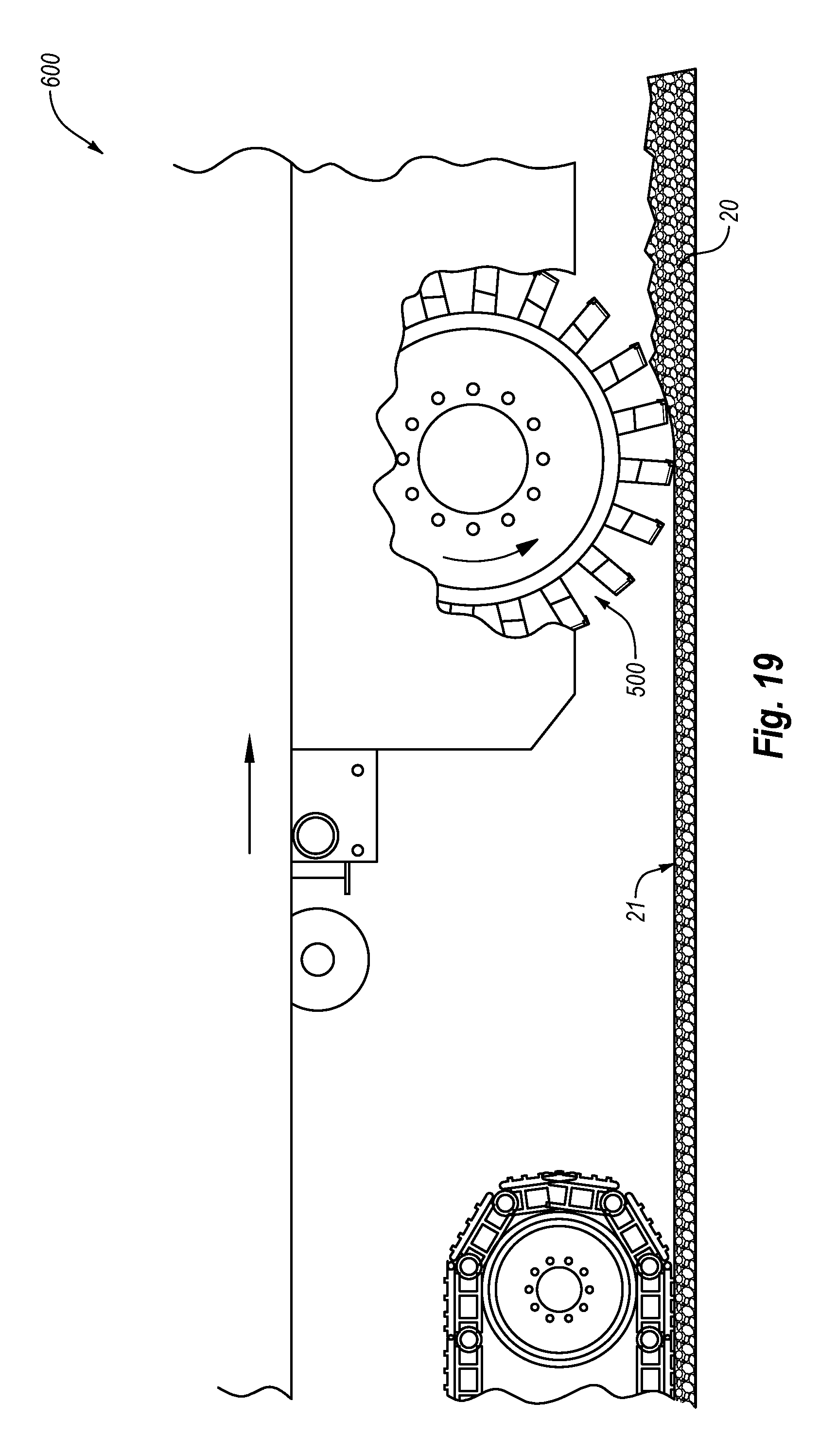
XML
uspto.report is an independent third-party trademark research tool that is not affiliated, endorsed, or sponsored by the United States Patent and Trademark Office (USPTO) or any other governmental organization. The information provided by uspto.report is based on publicly available data at the time of writing and is intended for informational purposes only.
While we strive to provide accurate and up-to-date information, we do not guarantee the accuracy, completeness, reliability, or suitability of the information displayed on this site. The use of this site is at your own risk. Any reliance you place on such information is therefore strictly at your own risk.
All official trademark data, including owner information, should be verified by visiting the official USPTO website at www.uspto.gov. This site is not intended to replace professional legal advice and should not be used as a substitute for consulting with a legal professional who is knowledgeable about trademark law.