Panel structure
Carlson , et al.
U.S. patent number 10,647,083 [Application Number 15/628,055] was granted by the patent office on 2020-05-12 for panel structure. This patent grant is currently assigned to ZEPHYROS, INC.. The grantee listed for this patent is Zephyros, Inc.. Invention is credited to Kearney Barton, David Carlson, Matthew Harthcock, Brandon Madaus, Charles L. Taylor, Jason Walker.

| United States Patent | 10,647,083 |
| Carlson , et al. | May 12, 2020 |
Panel structure
Abstract
A panel structure and a method of forming the panel structure are disclosed. The panel structure typically includes at least one panel associated with a material. The panel structure has been found particularly advantageous for use as an interior panel of an airplane.
| Inventors: | Carlson; David (Rochester Hills, MI), Madaus; Brandon (Shelby Township, MI), Harthcock; Matthew (Oakland Township, MI), Barton; Kearney (Oak Island, NC), Taylor; Charles L. (Arlington, TX), Walker; Jason (Lenox, MI) | ||||||||||
|---|---|---|---|---|---|---|---|---|---|---|---|
| Applicant: |
|
||||||||||
| Assignee: | ZEPHYROS, INC. (Romeo,
MI) |
||||||||||
| Family ID: | 35512482 | ||||||||||
| Appl. No.: | 15/628,055 | ||||||||||
| Filed: | June 20, 2017 |
Prior Publication Data
| Document Identifier | Publication Date | |
|---|---|---|
| US 20170282486 A1 | Oct 5, 2017 | |
Related U.S. Patent Documents
| Application Number | Filing Date | Patent Number | Issue Date | ||
|---|---|---|---|---|---|
| 13292686 | Nov 9, 2011 | 9688050 | |||
| 11151957 | Dec 6, 2011 | 8070994 | |||
| 60581190 | Jun 18, 2004 | ||||
| Current U.S. Class: | 1/1 |
| Current CPC Class: | B29C 44/186 (20130101); B32B 5/20 (20130101); B32B 7/02 (20130101); B32B 3/12 (20130101); E04C 2/365 (20130101); B32B 5/18 (20130101); B29C 44/1228 (20130101); B29L 2031/776 (20130101); B32B 2262/106 (20130101); B32B 2307/102 (20130101); B32B 2307/732 (20130101); B32B 2262/101 (20130101); B32B 2419/00 (20130101); B32B 2479/00 (20130101); Y10T 428/24157 (20150115); B32B 2307/304 (20130101); B32B 2509/00 (20130101); B32B 2439/00 (20130101); B32B 2250/40 (20130101); B29K 2995/0002 (20130101); B32B 2605/00 (20130101); B32B 2262/0261 (20130101) |
| Current International Class: | B32B 3/12 (20060101); B32B 5/18 (20060101); B29C 44/18 (20060101); B29C 44/12 (20060101); B32B 5/20 (20060101); E04C 2/36 (20060101); B32B 7/02 (20190101) |
References Cited [Referenced By]
U.S. Patent Documents
| 2744042 | May 1956 | Pace |
| 3249659 | May 1966 | Voelker |
| 4049855 | September 1977 | Cogan |
| 4234648 | November 1980 | Patz |
| 4273818 | June 1981 | Buchs |
| 4291079 | September 1981 | Hom |
| 4294329 | October 1981 | Rose et al. |
| 4318453 | March 1982 | Rose et al. |
| 4348442 | September 1982 | Figge |
| 4421201 | December 1983 | Nelson et al. |
| 4421811 | December 1983 | Rose et al. |
| 4427481 | January 1984 | Smith et al. |
| 4476183 | October 1984 | Holtrop et al. |
| 4538380 | September 1985 | Colliander |
| 4541879 | September 1985 | Riel |
| 4557961 | December 1985 | Gorges |
| 4601769 | July 1986 | DeHoff |
| 4693775 | September 1987 | Harrison |
| 4724243 | February 1988 | Harrison |
| 4749434 | June 1988 | Harrison |
| 4757665 | July 1988 | Hardigg |
| 4769166 | September 1988 | Harrison |
| 4778845 | October 1988 | Tschan et al. |
| 4871590 | October 1989 | Merz et al. |
| 4898630 | February 1990 | Kitoh et al. |
| 4908273 | March 1990 | Ureeh et al. |
| 4922596 | May 1990 | Wycech |
| 4923902 | May 1990 | Wycech |
| 4978562 | December 1990 | Wycech |
| 4995545 | February 1991 | Wycech |
| 4996090 | February 1991 | Steinke et al. |
| 5037498 | August 1991 | Umeda |
| 5124186 | June 1992 | Wycech |
| 5212003 | May 1993 | Homer |
| 5238725 | August 1993 | Effing et al. |
| 5242637 | September 1993 | Inoue et al. |
| 5266133 | November 1993 | Hanley et al. |
| 5274006 | December 1993 | Kagoshima et al. |
| 5328744 | July 1994 | Kaufmann et al. |
| 5338594 | August 1994 | Wang et al. |
| 5342873 | August 1994 | Merz et al. |
| 5382606 | January 1995 | Butikofer |
| 5445861 | August 1995 | Newton et al. |
| 5470886 | November 1995 | Makhlouf et al. |
| 5475039 | December 1995 | Butikofer |
| 5648401 | July 1997 | Czaplicki et al. |
| 5653836 | August 1997 | Mnich et al. |
| 5712317 | January 1998 | Makhlouf et al. |
| 5763813 | June 1998 | Cohen et al. |
| 5783272 | July 1998 | Wong |
| 5841079 | November 1998 | Parente |
| 5884960 | March 1999 | Wycech |
| 5894071 | April 1999 | Merz et al. |
| 5932680 | August 1999 | Heider |
| 5942330 | August 1999 | Kelley et al. |
| 5948508 | September 1999 | Pastore et al. |
| 5964979 | October 1999 | George et al. |
| 5980174 | November 1999 | Gallagher et al. |
| 5985435 | November 1999 | Czaplicki et al. |
| 5994422 | November 1999 | Born et al. |
| 6004425 | December 1999 | Born et al. |
| 6030701 | February 2000 | Johnson et al. |
| 6039287 | March 2000 | Liston et al. |
| 6039832 | March 2000 | McCarville |
| 6040350 | March 2000 | Fukui |
| 6057382 | May 2000 | Karim et al. |
| 6077884 | June 2000 | Hess et al. |
| 6093468 | July 2000 | Toms et al. |
| 6096791 | August 2000 | Born et al. |
| 6103784 | August 2000 | Hilborn et al. |
| 6110567 | August 2000 | Bird |
| 6133335 | October 2000 | Mahoney et al. |
| 6136398 | October 2000 | Willett et al. |
| 6136944 | October 2000 | Stewart et al. |
| 6153302 | November 2000 | Karim et al. |
| 6158690 | December 2000 | Wadey et al. |
| 6162504 | December 2000 | Hubert et al. |
| 6173807 | January 2001 | Welch et al. |
| 6174932 | January 2001 | Pachl et al. |
| 6179086 | January 2001 | Bansemir et al. |
| 6179943 | January 2001 | Welch et al. |
| 6180206 | January 2001 | Kain, Jr. |
| 6182787 | February 2001 | Kraft et al. |
| 6187411 | February 2001 | Palmer |
| 6218442 | April 2001 | Hilborn et al. |
| 6220388 | April 2001 | Sanborn |
| 6228449 | May 2001 | Meyer |
| 6232433 | May 2001 | Narayan |
| 6235842 | May 2001 | Kuwano et al. |
| 6263635 | July 2001 | Czaplicki |
| 6277898 | August 2001 | Pachl et al. |
| 6287669 | September 2001 | George et al. |
| 6298633 | October 2001 | McCorkle et al. |
| 6303672 | October 2001 | Papalos et al. |
| 6312668 | November 2001 | Mitra et al. |
| 6319964 | November 2001 | Blank et al. |
| 6348513 | February 2002 | Hilborn et al. |
| 6350791 | February 2002 | Feichtmeier et al. |
| 6376564 | April 2002 | Harrison |
| 6403222 | June 2002 | Harrison |
| 6405978 | June 2002 | Dean et al. |
| 6419305 | July 2002 | Larsen |
| 6429244 | August 2002 | Rinka et al. |
| 6432475 | August 2002 | Yamamoto et al. |
| 6437055 | August 2002 | Moriarity et al. |
| 6439340 | August 2002 | Shirvan |
| 6440257 | August 2002 | Zhou et al. |
| 6441075 | August 2002 | Hirata et al. |
| 6441081 | August 2002 | Sadatoshi et al. |
| 6444149 | September 2002 | Valentinsson |
| 6444713 | September 2002 | Pachl et al. |
| 6448338 | September 2002 | Born et al. |
| 6451231 | September 2002 | Harrison et al. |
| 6451876 | September 2002 | Koshy |
| 6455146 | September 2002 | Fitzgerald |
| 6455476 | September 2002 | Imai et al. |
| 6467834 | October 2002 | Barz et al. |
| 6471285 | October 2002 | Czaplicki et al. |
| 6479560 | November 2002 | Freitag et al. |
| 6482486 | November 2002 | Czaplicki et al. |
| 6486256 | November 2002 | Tarbutton et al. |
| 6506494 | January 2003 | Brandys et al. |
| 6511411 | January 2003 | Brown |
| 6518347 | February 2003 | Boyd et al. |
| 6537413 | March 2003 | Hochet et al. |
| 6548593 | April 2003 | Merz et al. |
| 6551441 | April 2003 | Sato et al. |
| 6561571 | May 2003 | Brennecke |
| 6565942 | May 2003 | Anderson et al. |
| 6573309 | June 2003 | Reitenbach et al. |
| 6607831 | August 2003 | Ho et al. |
| 6611659 | August 2003 | Meisiek |
| 6617366 | September 2003 | Sueda et al. |
| 6620501 | September 2003 | Kassa et al. |
| 6667089 | December 2003 | Barker |
| 6668457 | December 2003 | Czaplicki |
| 6670291 | December 2003 | Tompkins et al. |
| 6682818 | January 2004 | Czaplicki et al. |
| 6706772 | March 2004 | Czaplicki et al. |
| 6730713 | May 2004 | Czaplicki |
| 6740379 | May 2004 | Congard |
| 6740399 | May 2004 | George et al. |
| 6753379 | June 2004 | Kawate et al. |
| 6774171 | August 2004 | Kassa |
| 6776869 | August 2004 | Schenkel |
| 6777079 | August 2004 | Zhou et al. |
| 6787065 | September 2004 | Schapira et al. |
| 6787579 | September 2004 | Czaplicki et al. |
| 6787593 | September 2004 | Bell et al. |
| 6787605 | September 2004 | Clough et al. |
| 6787606 | September 2004 | Chen |
| 6790597 | September 2004 | Dershem et al. |
| 6790906 | September 2004 | Chaignon et al. |
| 6797371 | September 2004 | Gehlsen et al. |
| 6800157 | October 2004 | Tarbutton et al. |
| 6800680 | October 2004 | Stark et al. |
| 6805768 | October 2004 | Agarwal et al. |
| 6806320 | October 2004 | Everaerts et al. |
| 6811864 | November 2004 | Czaplicki et al. |
| 6820192 | November 2004 | Cho et al. |
| 6820337 | November 2004 | Buge et al. |
| 6838509 | January 2005 | Shimo et al. |
| 6846559 | January 2005 | Czaplicki et al. |
| 6855393 | February 2005 | Ayres |
| 6860186 | March 2005 | Cohen |
| 6862863 | March 2005 | McCorkle et al. |
| 6884055 | April 2005 | Cox |
| 6884854 | April 2005 | Schoenfeld et al. |
| 6887914 | May 2005 | Czaplicki et al. |
| 6890964 | May 2005 | Czaplicki et al. |
| 6893733 | May 2005 | Obeshaw |
| 6894082 | May 2005 | Brantl et al. |
| 6911109 | June 2005 | Giroux et al. |
| 8070994 | December 2011 | Carlson |
| 9688050 | June 2017 | Carlson |
| 2002/0009582 | January 2002 | Golden |
| 2002/0070074 | June 2002 | Bongiovi |
| 2002/0119311 | August 2002 | Tongbi |
| 2002/0120064 | August 2002 | Khandpur et al. |
| 2002/0123575 | September 2002 | Kato et al. |
| 2002/0136891 | September 2002 | Khandpur et al. |
| 2002/0137808 | September 2002 | Gehlsen et al. |
| 2003/0040598 | February 2003 | Wang |
| 2003/0187129 | October 2003 | Bell et al. |
| 2004/0033324 | February 2004 | Meyer |
| 2004/0063800 | April 2004 | Brantl et al. |
| 2004/0079478 | April 2004 | Merz |
| 2004/0131839 | July 2004 | Eagle |
| 2004/0131840 | July 2004 | Ferguson et al. |
| 2004/0180193 | September 2004 | Oda et al. |
| 2004/0181013 | September 2004 | Schenkel |
| 2004/0197545 | October 2004 | Gehlsen et al. |
| 2004/0202881 | October 2004 | Everaerts et al. |
| 2004/0229000 | November 2004 | Khandpur et al. |
| 2004/0234774 | November 2004 | Cheng et al. |
| 2004/0253407 | December 2004 | Shah et al. |
| 2004/0266898 | December 2004 | Kassa et al. |
| 2005/0016677 | January 2005 | Carlson et al. |
| 2005/0020703 | January 2005 | Czaplicki et al. |
| 2005/0048276 | March 2005 | Wilson |
| 2005/0154089 | July 2005 | Taylor et al. |
| 2005/0159511 | July 2005 | Kramer |
| 2005/0159531 | July 2005 | Ferng et al. |
| 19919783 | Nov 2000 | DE | |||
| 0442178 | Feb 1990 | EP | |||
| 0360214 | Mar 1990 | EP | |||
| 0819723 | Jan 1998 | EP | |||
| 1022320 | Jul 2000 | EP | |||
| 1055699 | Nov 2000 | EP | |||
| 1123184 | Dec 2002 | EP | |||
| 0703931 | Oct 2003 | EP | |||
| 1240266 | Feb 2004 | EP | |||
| 0851894 | Apr 2004 | EP | |||
| 1272587 | May 2004 | EP | |||
| 1155084 | Jun 2004 | EP | |||
| 1431325 | Jun 2004 | EP | |||
| 1075498 | Jul 2004 | EP | |||
| 0820491 | Aug 2004 | EP | |||
| 0947529 | Aug 2004 | EP | |||
| 1185595 | Aug 2004 | EP | |||
| 1252217 | Aug 2004 | EP | |||
| 1449868 | Aug 2004 | EP | |||
| 1023413 | Sep 2004 | EP | |||
| 1155082 | Sep 2004 | EP | |||
| 1305376 | Sep 2004 | EP | |||
| 1155053 | Oct 2004 | EP | |||
| 1163308 | Oct 2004 | EP | |||
| 1471105 | Oct 2004 | EP | |||
| 1001893 | Nov 2004 | EP | |||
| 1115770 | Nov 2004 | EP | |||
| 1187888 | Nov 2004 | EP | |||
| 1574537 | Sep 2005 | EP | |||
| 1265489 | Mar 1972 | GB | |||
| 1291753 | Oct 1972 | GB | |||
| 56-004432 | Jan 1981 | JP | |||
| 57-117542 | Jul 1982 | JP | |||
| 4059819 | Feb 1992 | JP | |||
| 4059820 | Feb 1992 | JP | |||
| 9249730 | Sep 1997 | JP | |||
| 95/33785 | Dec 1995 | WO | |||
| 97/02967 | Jan 1997 | WO | |||
| 97/12929 | Apr 1997 | WO | |||
| 97/19124 | May 1997 | WO | |||
| 98/52997 | Nov 1998 | WO | |||
| 9902578 | Jan 1999 | WO | |||
| 00/12571 | Mar 2000 | WO | |||
| 00/12595 | Mar 2000 | WO | |||
| 00/13876 | Mar 2000 | WO | |||
| 00/20483 | Apr 2000 | WO | |||
| 00/37242 | Jun 2000 | WO | |||
| 00/37554 | Jun 2000 | WO | |||
| 00/39232 | Jul 2000 | WO | |||
| 00/40629 | Jul 2000 | WO | |||
| 00/52086 | Sep 2000 | WO | |||
| 01/57130 | Aug 2001 | WO | |||
| 01/88033 | Nov 2001 | WO | |||
| 02/070620 | Sep 2002 | WO | |||
| 02/088214 | Nov 2002 | WO | |||
| 03/011954 | Feb 2003 | WO | |||
| 03/040251 | May 2003 | WO | |||
| 03/054069 | Jul 2003 | WO | |||
| 03/059997 | Jul 2003 | WO | |||
| 03/072677 | Sep 2003 | WO | |||
| 03/078163 | Sep 2003 | WO | |||
| 03/095575 | Nov 2003 | WO | |||
| 04/055092 | Jul 2004 | WO | |||
| 04/060956 | Jul 2004 | WO | |||
| 04/060984 | Jul 2004 | WO | |||
| 04/062869 | Jul 2004 | WO | |||
| 04/065485 | Aug 2004 | WO | |||
| 04/076507 | Sep 2004 | WO | |||
| 04/085510 | Oct 2004 | WO | |||
| 04/085564 | Oct 2004 | WO | |||
| 04/099312 | Nov 2004 | WO | |||
| 04/104125 | Dec 2004 | WO | |||
| 05/007720 | Jan 2005 | WO | |||
| 05/035217 | Apr 2005 | WO | |||
| 05/047393 | May 2005 | WO | |||
| 04/050740 | Jun 2014 | WO | |||
Other References
|
"The Epoxy Book", Published by System Three Resins, Inc. Seattle, Washington. cited by applicant . "Expoxy Resins" Second Edition Encyclopedia of Polymer Science and Engineering, vol. 6, pp. 322-383 (1985). cited by applicant . Born et al., "Structural Bonding in Automotive Applications". cited by applicant . Dvorko. "One-Part Epoxy Compounds and Derived Foam Plastics", published Apr. 13, 2004. cited by applicant . Zalobsky et al., "Recommendations on Selection and Use of Cavity Reinforcement Materials" Proceedings of the 1999 Noise and Vibrations Conference. cited by applicant . Weber et al., "Requirements for Improved Performance of Specialty Sealing and Bonding Materials for Automotive Applications", SAE 2000 World Congress, Mar. 6-9, 2000. cited by applicant . Liu et at, "Validation of Epoxy Foam for Structural and Crash Application". 2004 SAE World Congress, Mar. 8-11, 2004. cited by applicant . Schulenburg et al., "Structural Adhesives--Improvements in Vehicle Crash Performance", 2004 SAE World Congress, Mar. 8-11, 2004. cited by applicant . Casey et al., Expandable Epoxy Foam: A Systematic Approach to Improve Vehicle Performance, 2004 SAE World Congress, Mar. 8-11, 2004. cited by applicant . Copending U.S. Appl. No. 10/783,326, filed Feb. 20, 2004. cited by applicant . Copending U.S. Appl. No. 11/089,712, filed Mar. 25, 2005. cited by applicant . Product Literature for Structural Adhesives and Structural Specialty Products. cited by applicant . International Search Report dated Nov. 28, 2605. PCT/US05/014385. cited by applicant. |
Primary Examiner: Grun; Robert J
Attorney, Agent or Firm: The Dobrusin Law Firm, P.C.
Parent Case Text
This application claims the benefit of the filing date of U.S. Provisional Application No. 60/581,190, the contents of which are expressly incorporated herein by reference.
Claims
What is claimed is:
1. An interior panel structure of a transportation vehicle, comprising: a first panel formed at least partially of a plastic material; a second panel formed at least partially of a porous material, the second panel being an outer panel that is closer to a body of the transportation vehicle than the first panel while the first panel is closer to an interior cabin of the transportation vehicle; and an activatable material intermediate the first panel and the second panel, the activatable material softens, expands, and cures upon exposure to heat; wherein a volume is defined between the first panel and the second panel and wherein the activatable material when activated, fills from about 5% to about 90% of the volume, and wherein the interior panel structure, when assembled and in use, provides at least one functional attribute selected from reinforcement, baffling, sound absorption, sound attenuation, baffling or sealing.
2. The interior panel structure as in claim 1, wherein the transportation vehicle is an airplane and the body of the transportation vehicle is a fuselage of the airplane.
3. The interior panel structure as in claim 1, wherein the activatable material is part of a composite that includes a support having a plurality of openings.
4. The interior panel structure as in claim 1, wherein the activatable material is epoxy-based.
5. The interior panel structure as in claim 1, wherein the activatable material is a thermoset, a thermoplastic or a combination thereof.
6. The interior panel structure as in claim 1, wherein the activatable material is adhered to either the first panel or the second panel.
7. The interior panel structure as in claim 1, wherein the first panel is formed of an epoxy/glass composite.
8. The interior panel structure as in claim 1, wherein space is formed between the activatable material when activated and the first panel.
9. The interior panel structure as in claim 3, wherein the support is a honeycomb structure located between the first and second panel.
10. The interior panel structure as in claim 9, wherein expansion of the activatable material provides adhesion between at least one of the panels and the support.
11. The interior panel structure as in claim 1, wherein the activatable material when activated has a compressive strength of about 1.5 MPa or greater.
12. A method of forming an interior panel structure of a transportation vehicle, comprising: providing a first panel formed at least partially of a plastic material, the first panel being an inner panel at least partially defining an interior cabin of the transportation vehicle; providing a second panel formed at least partially of a porous material, the second panel being an outer panel that is closer to a body of the transportation vehicle than the first panel; locating an activatable material that softens, expands, and cures upon exposure to heat and a support intermediate the first panel and the second panel; and exposing the activatable material to an elevated temperature for activating the activatable material to expand and form a foam whereby the interior panel structure, when assembled and in use, provides a functional attribute selected from reinforcement, baffling, sound absorption, sound attenuation, baffling or sealing to the panel structure, wherein a volume is defined between the first panel and the second panel and wherein the activatable material when activated, fills from about 5% to about 90% of the volume.
13. The method as in claim 12, wherein a volume is defined between the first panel and the second panel and wherein the foam, the support or both fill at least about 15% of the volume but less than about 75% of the volume.
14. The method as in claim 12, wherein the first panel is formed of an epoxy/glass composite.
15. The method as in claim 12, wherein, upon expansion, the activatable material expands to a volume that is at least 500% greater than its original unexpanded volume.
16. The method as in claim 12, wherein the support is a honeycomb structure located between the first and second panel having a plurality of openings for receiving the activatable material.
17. The method as in claim 16, wherein a plurality of spaces are formed between the foam in each of the plurality of openings and the first panel.
18. The method as in claim 12, wherein a plurality of spaces are formed between the activatable material when activated and the first panel.
19. The method as in claim 12, wherein expansion of the activatable material provides adhesion between at least one of the panels and the support.
Description
FIELD OF THE INVENTION
The present invention relates generally to a panel structure that incorporates one or more panels and a material for providing reinforcement, baffling, sealing, sound absorption, damping or attenuation, thermal insulation, combinations thereof or the like.
BACKGROUND OF THE INVENTION
For many years, industry, and particularly the transportation industry, has been concerned with designing innovative structures that assist in providing functional attributes such as reinforcement, baffling, sealing, sound absorption, damping or attenuation, thermal insulation, combinations thereof or the like to articles of manufacture such as airplanes, automotive vehicles, buildings, furniture or the like. In the interest of continuing such innovation, the present invention provides a panel structure having one or more desirable functional attributes
SUMMARY OF THE INVENTION
Accordingly, the present invention provides a panel structure having at least one panel and a material associated with the panel. In one desirable embodiment, the panel structure includes a first panel and a second panel with the material disposed therebetween. Typically, the material provides reinforcement, baffling, sealing, sound absorption, damping, attenuation, thermal insulation, combinations thereof or the like to the panel structure and/or an article of manufacture incorporating the panel structure. In one particular embodiment, the panel structure has been particularly useful when employed for interior portions of transportation vehicles and particularly aerospace vehicles such as airplanes.
BRIEF DESCRIPTION OF THE DRAWINGS
The features and inventive aspects of the present invention will become more apparent upon reading the following detailed description, claims and drawings, of which the following is a brief description:
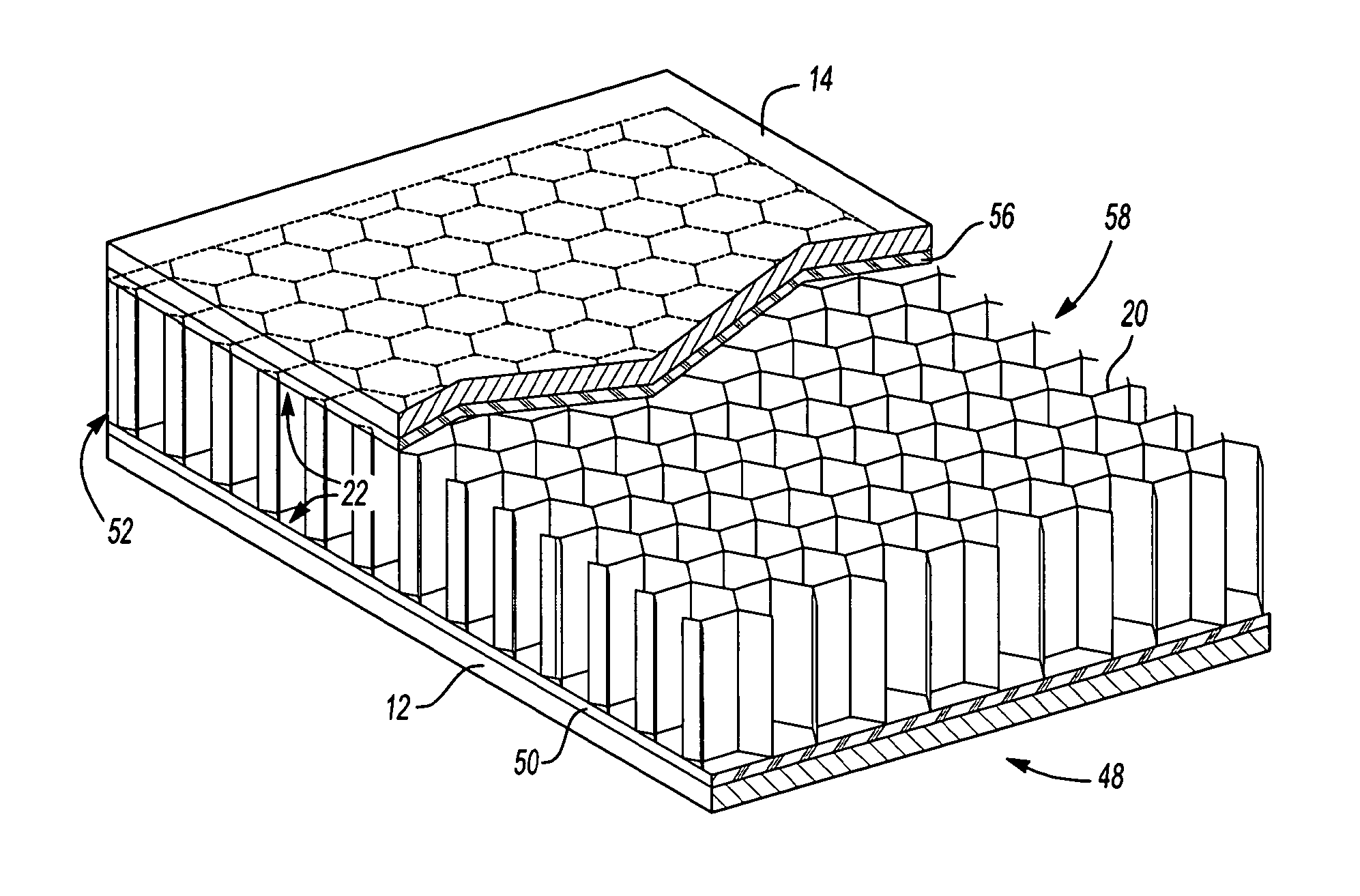
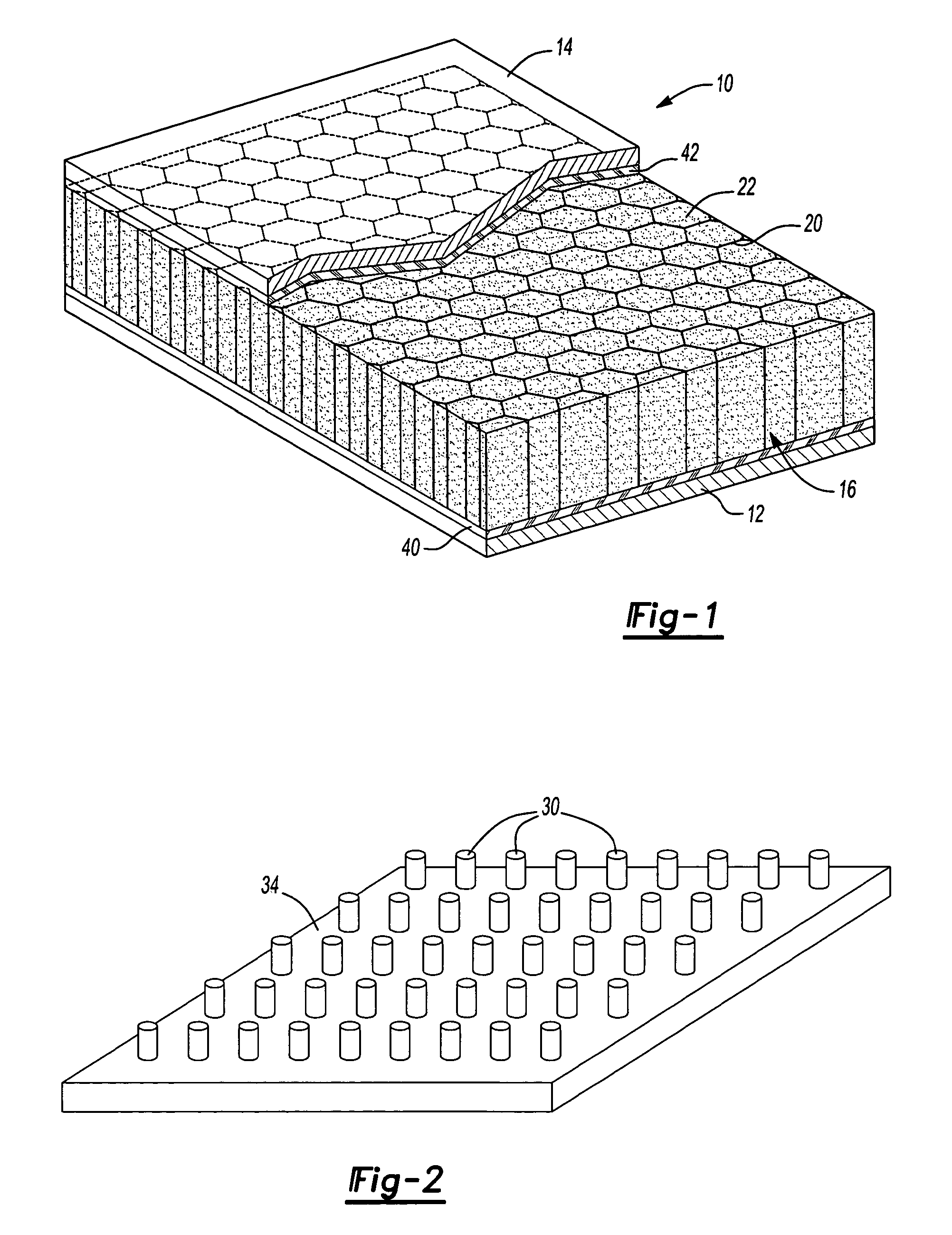
FIG. 1 is a perspective partially cut-away view of a portion of an exemplary panel structure formed in accordance with an aspect of the present invention.
FIG. 2 is a perspective view of a sheet with masses of material distributed thereon according to an exemplary aspect of the present invention.
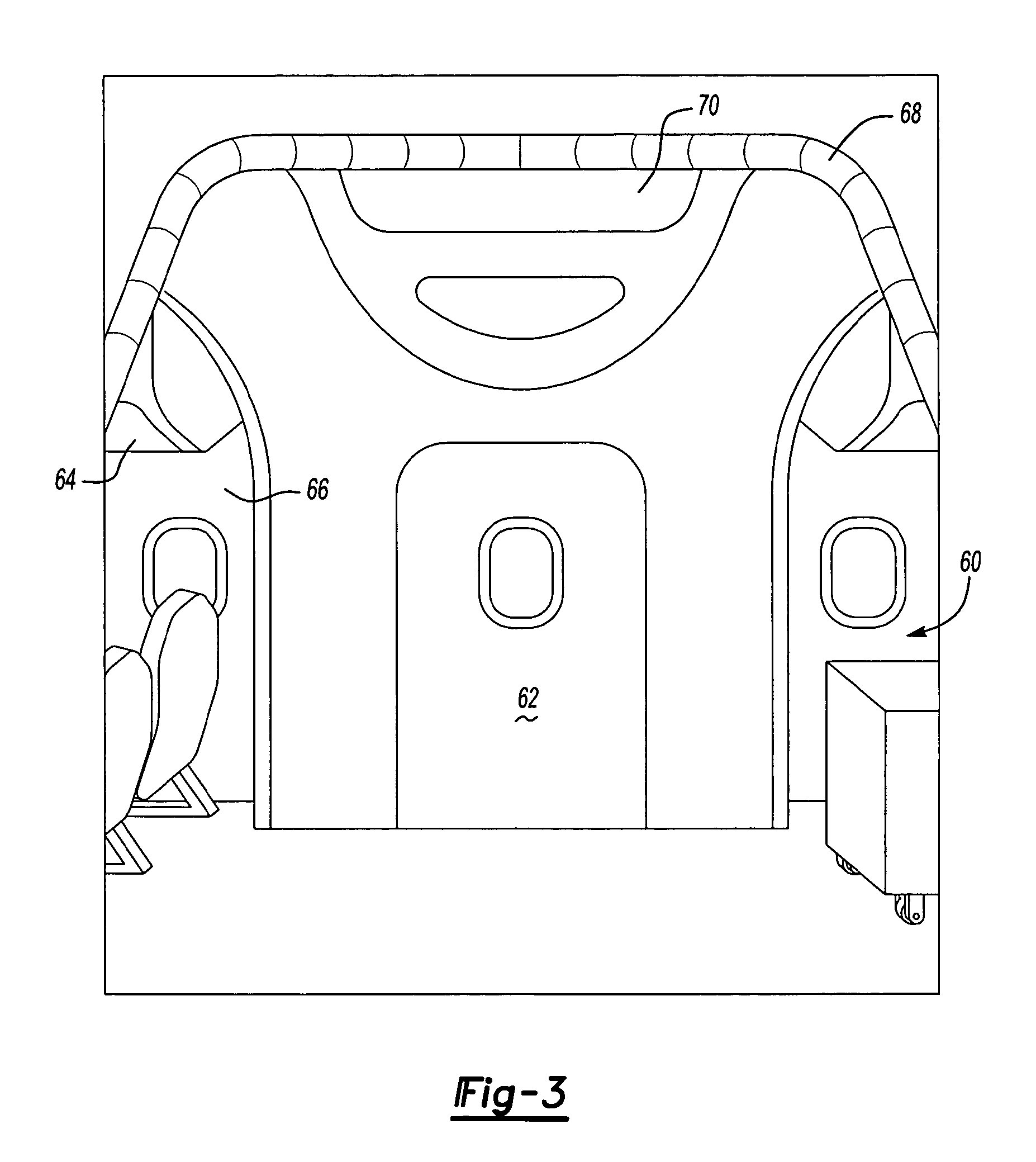
FIG. 3 is a perspective view of an exemplary interior of an airplane in accordance with an aspect of the present invention.
FIG. 4A is a perspective partially cut-away view of a portion of an exemplary panel structure prior to activation of a material of the structure.
FIG. 4B is a perspective partially cut-away view of the portion the exemplary panel structure of FIG. 4A after activation of the material of the structure.
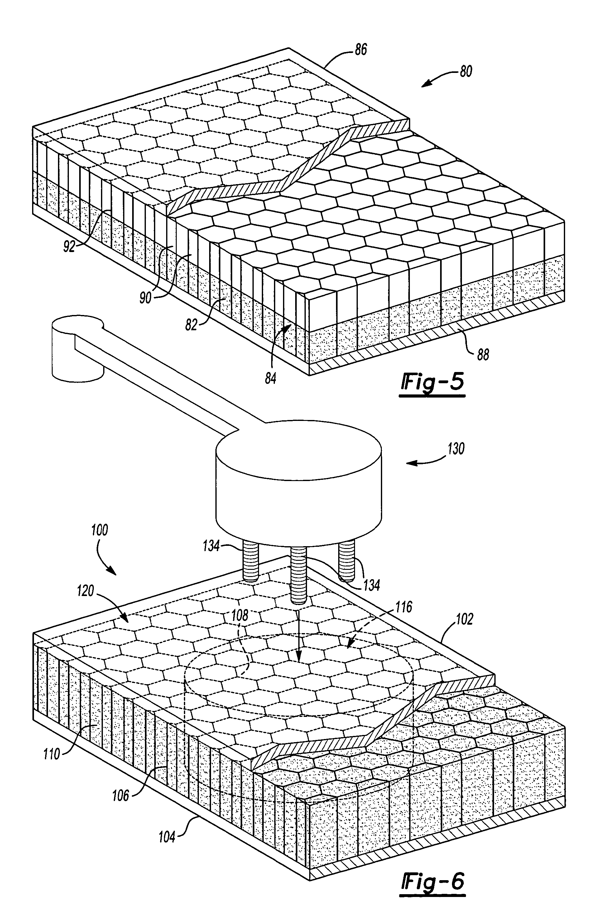
FIG. 5 is a perspective view of an additional or alternative embodiment of a panel structure according to the present invention.
FIG. 6 is a perspective view of another additional or alternative embodiment a of a panel structure according to the present invention.
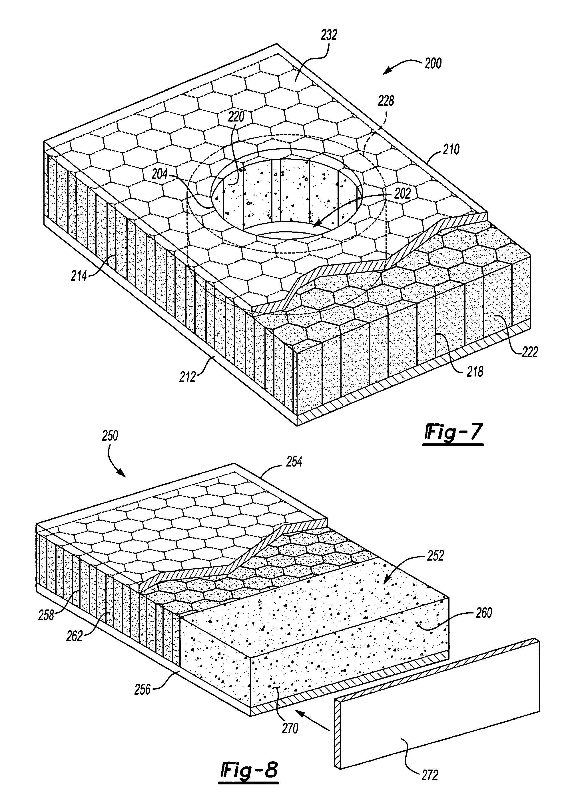
FIG. 7 is a perspective view of another additional or alternative embodiment a of a panel structure according to the present invention.
FIG. 8 is a perspective view of another additional or alternative embodiment a of a panel structure according to the present invention.
DETAILED DESCRIPTION OF THE INVENTION
The invention relates to a panel structure of an article of manufacture and a method of forming the panel structure. The panel structure includes at least one panel and a material associated with (e.g., laminated or layered with) the at least one panel. Typically, the material is disposed between a first panel and second panel, although not necessarily required. The material is also typically a functional material that provides reinforcement, baffling, sealing, sound absorption, sound damping, sound attenuation, thermal insulation, combinations thereof or the like to the panel structure and/or to an article of manufacture incorporating the panel structure.
It is contemplated that the panel structure may be employed in a variety of articles. Exemplary articles include household or industrial appliance (e.g., dishwashers, washing machines, dryers or the like), furniture, storage containers or the like. In one embodiment, the panel structure is employed in a transportation vehicle (e.g., an automotive vehicle, a boat, an airplane or the like). When used for a transportation vehicle, the panel structure has been found to be particularly useful as an interior panel structure (e.g., a panel exposed to an interior cabin portion of the vehicle). In one embodiment, the panel structure has been found particularly useful as an interior panel structure of an aerospace vehicle (e.g., an airplane). As such, the panel structure of the present invention is primarily discussed in relation to an airplane, however, the invention should not be so limited unless otherwise stated.
Referring to FIG. 1, there is illustrated an exemplary embodiment of an interior panel structure 10 of an airplane in accordance with an aspect of the present invention. The panel structure 10 includes a first or inner panel 12 opposite a second or outer panel 14. The panel structure 10 also includes a composite 16 intermediate the first panel 12 and second panel 14.
It should be understood that the panels (e.g., the first and second panels 12, 14) of the present invention may be as thick or thin as needed or desired. For exemplary purposes, the thickness of the panels is typically at least about 0.03 mm but may be less, more typically at least about 0.2 mm and even more typically at least about 0.4 mm and is typically less than about 0.5 cm but may be greater, typically less than about 3 mm and even more typically less than about 1 mm.
The first panel 12 and the second panel 14 are shown as being substantially planar, however, it is contemplated that the first and second panels 12, 14 may be contoured as desired or needed. Typically, such contouring will depend upon the location that the panels 12, 14, the panel structure 10 or both are to be installed within the airplane or other article of manufacture.
The first panel 12 and second panel 14 may be formed of a variety of materials. Exemplary materials include metals, polymeric materials (e.g., plastics, elastomers, thermoplastics, thermosets, combinations thereof or the like). The materials of the panels may also be reinforced with minerals, fibrous materials (e.g., glass, carbon or nylon fibers), combinations thereof or the like. In one embodiment, the first panel 12 is formed of fiberglass/plastic composite and the second panel 14 is formed of a metal or metal alloy.
The composite 16, as shown, includes a support 20 and a material 22 (e.g., a matrix material or functional material) integrated with the support 20. It should be noted, however, that it is contemplated that the panel structure 10 may include only the material 22 without the support 20. The support 20 may be formed in a variety of shapes and configurations such as corrugations, lattice structures or the like. In the particular embodiment shown, the support 20 is a honeycomb structure defining a plurality of openings into which the material 22 has been placed or located.
When included, the support is typically formed of a polymeric material such as a thermoplastic or thermoset polymeric material, which may or may not be reinforced with minerals or fibrous materials (e.g., glass, carbon or nylon fibers). It is contemplated, however, that the support may be formed of several additional or alternative materials as well such as metals, fibrous materials (e.g. cardboard, paper materials), combinations thereof or the like which may be coated or uncoated.
The Material
The material 22 typically provides the panel structure 10 (or the article of manufacture including the panel structure) with reinforcement, baffling, sealing, sound absorption, damping or attenuation, thermal insulation, combinations thereof or the like. Thus, the material may exhibit relatively high strength to weight ratios, relatively high sound attenuation characteristics, combinations thereof or the like.
The material 22 is typically selected so as to be activatable under a desired condition. As used herein, activatable means that the material softens (e.g, melts), cures, expands, foams or a combination thereof upon exposure to a condition or upon the combination of particular chemicals (e.g., 2-component materials). Typically, the material, upon activation, can wet, and preferably bond to adjacent surfaces (e.g., the surfaces provided by the panels 12, 14, the support 20 or a combination thereof).
In a preferred embodiment, typically for reinforcement, the material has a post-cure glass transition temperature that is greater than any temperatures to which the material may be exposed while in its intended environment of use (e.g., in an airplane or automotive vehicle). Exemplary post-cure glass transition temperatures may be greater than about 80 degrees Celsius and more preferably greater than about 100 degrees Celsius. Other desired characteristics of the material might include good adhesion retention and degradation resistance particularly in adverse environments such as highly variable temperature environments, high dynamic activity environments, combinations thereof or the like. For particular embodiments (e.g., where damping or sound absorption is desired), the material may stay in a softer or goopy state or it may become more solid particularly if it has a lower post-cure glass transition temperature.
The material may be a thermoplastic, a thermoset or a blend thereof. According to one embodiment, the material is as an epoxy-containing material, an ethylene-containing polymer, an acetate or acrylate containing polymer, or a mixture thereof, which when compounded with appropriate ingredients (typically a blowing agent, a curing agent, and perhaps a filler), typically expands, cures or both in a reliable and predictable manner upon the application of heat or another activation stimulus. Thus, according to one embodiment, an exemplary material may be a heat-activated and/or epoxy-based resin having foamable characteristics. Of course, the material may be activated by other conditions or stimuli. Generally, it is contemplated that, particularly for higher expansion materials, the activatable material may include or be based upon an elastomer (e.g., rubber), an acetate, an acrylate or combinations thereof.
From a chemical standpoint for a thermally-activated material, such material is usually initially processed as a thermoplastic material before curing. After curing, the material typically becomes a thermoset material that is fixed and incapable of any substantial flow. Examples of preferred formulations that are commercially available include those available from L&L Products, Inc. of Romeo, Mich., under the designations L-0502, L-0504, L-1066, L-2105, L-2663, L-5204, L-5206, L-5207, L-5208, L-5214, L-5218, L-5222, L-5248, L-7102, L-7220, L-8000, L-8100 or combinations thereof. It is also contemplated that the material may have a fiberglass or other fabric material integrated to one or more sides of the material and/or within the material.
The material 22 may be formed using a variety of processing techniques, machines and the like. Possible processing techniques for the preferred materials include injection molding, blow molding, thermoforming, extrusion with a single or twin screw extruder or extrusion with a mini-applicator extruder. The material may also be formed as a blown or a cast film, particularly prior to expansion.
Though preferred materials are disclosed other suitable material may be used in conjunction with the present invention. The choice of the material 22 used will typically be dictated by performance requirements and economics of the specific application and requirements. Examples of other possible materials include, but are not limited to, polyolefins, copolymers and terpolymers with at least one monomer type an alpha-olefin, phenol/formaldehyde materials, phenoxy materials, polyurethanes typically with high glass transition temperatures (including polyureas), and mixtures or composites thereof (optionally including solid or porous metals). See also, U.S. Pat. Nos. 5,766,719; 5,755,486; 5,575,526; 5,932,680 (incorporated herein by reference).
In applications where the material is a heat activated material, such as when a thermally melting, expanding, curing and/or foaming material is employed, an important consideration involved with the selection and formulation of the material can be the temperature at which the material activates, cures or both. In most applications, it is undesirable for the material to activate at room temperature or the ambient temperature in a production or assembly environment. Typically, it is desirable for the material to activate at higher processing temperatures. Typical activation temperature[s] is at least about 120.degree. F. or less, more typically at least about 190.degree. F., still more typically at least about 230.degree. F. and even more typically at least about 265.degree. F. and typically less than about 600.degree. F. or greater, more typically less than about 450.degree. F. and even more typically less than about 350.degree. F. and still more typically less than about 275.degree. F. Exposure to such temperatures typically occurs for a period of time that is at least about 10 minutes or less, more typically at least about 20 minutes and even more typically at least about 30 minutes and typically less than about 300 minutes or greater, more typically less than about 180 minutes and even more typically less than about 90 minutes.
Although the material 22 may be heat activated, it may be otherwise additionally or alternatively activated by other stimuli to cure, expand, bond, combinations thereof or the like. Without limitation, such material may be activated by alternative stimuli such as, pressure, moisture, chemicals, ultraviolet radiation, electron beam, induction, electromagnetic radiation or by other ambient conditions. As particular examples, the material may be a two-component adhesive material that expand, cure, adhere or a combination thereof upon adding one component to the other. Examples of first component/second component materials include epoxy/amine materials and epoxy/acid materials.
Manufacture
The panel structure of the present invention may be formed according to a variety of protocols. The material may be applied directly to the panels, the support or both. Thereafter, the material may be activated to soften, cure, expand or a combination thereof to wet and adhere the material to the panels, the support or both. It is also contemplated that the material may be pre-activated and subsequently applied to the panels, the support or both. Further, it is contemplated that one or more adhesives may be employed for attaching the panels, the material, the support or combinations thereof to each other.
When the material 22 is incorporated with a support 20 having openings such as the honeycomb structure of FIG. 1, various different techniques may be used to provide the material 22 to the openings. In one embodiment, and referring to FIG. 2, masses 30 of the material 22 may be provided on a surface 34, which may be part of one of the panels 12, 14, of the panel structure 10 or of another panel, according to the pattern of openings of the support 20. Then, the masses 30 are located within the openings of the support 20, while they remain upon the surface 34 by bringing the surface 34 and support 22 closer to each other. In such an embodiment, the masses 30 may be provided manually or automatically to the surface 34. For instance, the masses 30 may be provided to the surface 34 using an extruder (e.g., using extrude-in-place techniques). It may also be possible to manually or automatically (e.g., with an extruder and or extrude-in-place techniques) apply masses 30 of the material 22 directly into the opening of the support 20. Techniques for extruding such materials in these embodiments are disclosed in commonly owned U.S. Pat. No. 5,358,397 and U.S. patent application Ser. No. 10/342,025, filed Jan. 14, 2003, titled "Method and Apparatus for Applying Flowable Materials", both of which are incorporated herein by reference for all purposes.
In an alternative embodiment, and referring to FIG. 2, it is contemplated that both the panel may be formed of a material (e.g., an expandable material) as well as the masses 30 of material. In such an embodiment the panel of material would typically serves to adhere the masses and the support to one of the panels 12, 14.
In another embodiment, the material 22 is applied to the support 20 by dispensing multiple (e.g. 3, 6, 20, 100 or more) masses (e.g., as small pellets or as a powder) of the material 22 into each of the openings of the support 20. Such masses may be poured, sprinkled or otherwise dispensed into the openings of the support 20.
The panels 12, 14 may be attached to the support 20, the material 22 or both before, during or after activation of the material 22. Thus, in one embodiment, the material 22 is activated to soften, expand, cure or a combination thereof followed by attaching the panels 12, 14 to the material. In the embodiment illustrated, the material 22 is activated to soften (e.g., melt), expand and wet the support 20 while simultaneously and/or thereafter to cure and adhere to the support 20 thereby forming the composite 16. Thereafter, the panels 12, 14 are respectively adhered to opposite sides of the composite 16 with adhesive layers 40, 42.
In another embodiment, one or both of the panels 12, 14 are placed adjacent the material 22, the support 20 or both (e.g., placed adjacent opposite sides of the material 22 and/or the support 20). Then, the material 22 is activated to soften (e.g., melt), expand and wet the support 20 and one or both of the panels 12, 14 while simultaneously and/or thereafter curing and adhering to the support 20 and one or both of the panels 12, 14. In such an embodiment, the material 22, the composite 16 or both can be attached to the panels 12, 14 without the additional adhesive layers 40, 42, although such adhesive layers may be additionally included. Also, in such an embodiment, temporary attachments (e.g., fasteners) may be employed to located the panels 12, 14, the material 22 and, if used, the support 20 relative to each other at least until activation of the material 22.
In one particular embodiment, referring to FIGS. 4A and 4B, there is a panel structure 48 with a first layer 50 of the material 22 positioned between the first panel 12 and a first side 52 of the support 20 and a second layer 56 of the material 22 positioned between the second panel 14 and a second side 58 of the support 20.
Once assembled, typically either automatically, manually or a combination thereof, the layers 50, 56 of material 22 are activated to soften, expand and cure. As can be seen, the layers 50, 56 wet and adhere to both the support 20, particularly the sides 52, 58 of the support and to side surface of the panels 12, 14. The layers 50, 56 can also expand into and fill at least a portion of the opening of the support 20. Advantageously, the layers 50, 56 may be able to provide reinforcement, structural integrity, sound and/or vibration dampening, sound absorption or a combination thereof to the panel structure 48. While, the material 22 in FIGS. 4A and 4B is not shown as being located in the more central openings of the support 20 as discussed in previous embodiments, it is contemplated that such material may additionally be so located and employed as previously described.
In a preferred embodiment, the material 22 of the panel structure is heat activated in a panel press. For activation, the components (i.e., the material 22, the layers 52, 56, the support 20 and the panels 12, 14 or a combination thereof) of the panel structure may be assembled as described above or otherwise. Thereafter, the panel structure is fed to a panel press where it experiences temperatures that are typically above about 150.degree. F., more typically above about 200.degree. F. and even more typically above about 265.degree. F. and below about 550.degree. F., more typically below about 420.degree. F. and even more typically below about 350.degree. F. Such exposure is typically for a time period of at least about 10 minutes, more typically at least about 30 minutes and even more typically at least about 60 minutes and less than about 360 minutes more typically less than about 180 minutes and even more typically less than about 90 minutes. While in the press, a pressure is typically applied to the panel structure urging the components (i.e., the material 22, the layers 52, 56, the support 20 and the panels 12, 14 or a combination thereof) of the panel structure toward each other. Advantageously, typically for reinforcement, the material can provide more thorough adhesion to the support.
It is additionally contemplated that other additional or alternative techniques may be used to assist in the formation of the panel structure. Such techniques can include vacuum forming and baking, autoclaving and pressure, others or combinations thereof. Such techniques can assist in forming panels with contours. Heats and time period for these techniques can be the same as those discussing above or may be different depending upon the activatable material used.
Application
As discussed, the panel structure 10 may be used in several different articles of manufacture such as transportation vehicles (e.g., automotive vehicles), buildings, furniture or the like. Typically, although not required, the panel structure is employed for forming the interior of one of these articles of manufacture. In such an embodiment wherein the panel structure includes at least two panels, at least one panels of the panel structure is typically exposed to and/or at least partially defines an inner open area of the article while another panel of the panel structure is closer to a body of the article. For example, in a building, the inner or first panel would typically be exposed to and/or define the interior of a room of the building while the outer or second panel would typically be closer to the outer building material (e.g., brick, siding or the like) of the building. As another example, in an automotive vehicle, the inner or first panel would typically be exposed to and/or at least partially define an interior cabin of the vehicle while the outer or second panel would typically be closer to the body of the vehicle.
Referring additionally to FIG. 3, it is contemplated that the panel structure 10 can be employed in several locations within the interior 60. For example, and without limitation, the panel may form part or the entirety of a door 62, an overhead storage compartment 64, a side panel 66, an archway 68, a ceiling panel 70, combinations thereof or the like. The panel may also be employed in an airplane wing, floor structure or the like.
When the structure 10 is employed within an airplane the first or inner panel 12 will typically be exposed and/or at least partially define the interior cabin 60 of the airplane. The second or outer panel 14 is typically closer to the fuselage of the airplane. Of course, the panels may be reversed. Moreover, the panel may be located away from the fuselage and may or may not be exposed to the interior cabin of the plane. For example, the panel may be completely enclosed (e.g., within an interior door of a plane) or may be covered with carpet (e.g., as in a floor panel of a plane). It should be understood that the panel (e.g., the first panel) that is typically closest to the interior cabin 60 may be covered by an aesthetic covering such as paint, wallpaper, a plastic fascia, cloth, leather, combinations thereof or the like and may still define the interior cabin 60.
The panel structure 10 may be attached to the fuselage of the airplane according to a variety of techniques. Generally it is contemplated that the second or outer panel 14 may be connected directly or indirectly connected or attached to the fuselage and may be attached thereto with fasteners, adhesives, interference fits, support structures, combinations thereof or the like.
When the materials of the present invention are integrated into the support as shown and discussed in relation to FIG. 1, the materials can provide significant acoustical damping properties to the panels in addition to the other properties imparted to the panels. When, the materials are used on opposing sides of the support, as shown and discussed in relation to FIGS. 4A and 4B, the materials can provide significant structural integrity to the panels in addition to the other properties imparted to the panels. As such, it should be understood that the material integrated into the support may be different or may be the same as the material used to adhere to the opposing sides. For example, where the materials are different, it is contemplated that the material integrated into the support may volumetrically expand at least 10%, more typically at least 30% and even more typically 100% more than the expansion of the material on the sides. As used herein, a material that expands to a volume that is 210% of its original unexpanded volume volumetrically expands 10% more than a material that expands to 200% of its original volume, and similar calculations may be made for the other percentages. Generally, higher expanding materials can be more specifically tailored for acoustical dampening while the lower expanding material can be tailored far providing structural integrity.
As an addition or alternative to the previous embodiments, it is contemplated that that activated or activatable material, the support or a combination thereof may fill none, a portion, a substantial portion or substantially the entirety of a volume between two panels. The amount of the volume filled may depend upon considerations such desired strength, desired sound absorption or the like.
In FIG. 5, one embodiment of a panel structure 80 is illustrated as having an activated material 82 (e.g., a foam) that fills a portion of a volume 84 between a first panel 86 (e.g., a resistive face sheet) and a second panel 88. In the illustrated embodiment, the activated material 82 is located within openings 90 of a support 92. Typically, although not required, the material 82 (e.g., the foam and the voids or cells defined by the foam), the support 92 or both fill at least 5%, more typically at least 15% and even more typically at least 30% of the volume between the panels. It is also typical, although not required, for the material 82, the support 92 or both to fill less than 90%, more typically less than 75% and even more typically less than 60% of the volume between the panels.
The particular embodiment illustrated can, if desired, exhibit a relatively high degree of sound absorption due to one or more factors such as the materials used for the panel structure, the configuration of the components of the panel structure or other factors. Generally, the panels 86, 88 may be formed of any of the materials discussed herein or other materials. According to one preferred embodiment, however, the first panel 86 is formed of a fabric (e.g., upholstery, felt material, wire mesh) or non-fabric material that includes or is formed substantially entirely of a polymer, fiberglass, natural fiber, metal (e.g., aluminum, steel, magnesium, a combination thereof or the like), metal fibers, combinations thereof or the like, which may be woven into a fabric, molded, extruded or other wise formed or processed. The first panel 86 if typically formed of a material that allows sound waves to pass through it and the material may additionally provide some amount of sound impedance. Generally, it is contemplated that the material of the first panel may or may not be impervious to fluids.
The second panel 88, like the first, may also be formed of any of the suitable materials discussed herein. As one example, the second panel 88, may include or be formed substantially entirely of an epoxy/glass fiber prepreg or composite. The support 92 can also be formed of any of the suitable materials discussed herein. In the illustrated embodiment, the support 92 is a honeycomb structure similar to that described for FIG. 1.
For forming the panel structure of FIG. 5, the activated material may be located within the opening of the honeycomb according to any of the techniques discussed herein. According to one embodiment, activatable material is located adjacent the second panel 88 and expanded or foamed (e.g., by exposure to heat as described herein) into the openings 90 of the support 92 to whatever distance or degree is desired. Preferably, after activation, the activated material 82 occupies a volume that is at least 150%, more typically at least 400% and even more typically at least 800% of the volume occupied by the activatable material prior to activation. Advantageously, such an expansion of the activatable material allows for the activated material 82 to efficiently fill at least part of the volume 84 between the panels 86, 88.
As another addition or alternative to the previous embodiment, it is contemplated that the panel structure of the present invention may include a relatively high strength material throughout or within a region of the panel structure. Advantageously, such a material or region can assist providing structural integrity to the panel structure, particularly at locations where components are attached to the panel structure.
Referring to FIG. 6, an exemplary panel structure 100 is illustrated as having a first panel 102 and a second panel 104. The panel structure 100 also includes support 106 and one or more activated materials 108, 110 between the first panel 102 and the second panel 104. It should be understood that any of the components of the panel structure 100 can be formed of any of the suitable materials discussed herein or others unless otherwise specified. Moreover, the components may be assembled or applied to each other using any of the suitable techniques discussed herein or others, unless otherwise specified.
As can be seen, the panel structure 100 of FIG. 6 includes a relatively high strength region 116 as defined by the dashed line. Although shown as cylindrical, the region 116 may shaped as desired depending upon its intended use. The high strength region 116 is defined by the fact that its activated material 108 has a relatively high strength. For example, the material 108 can have a compressive strength that is at least about 0.7 MPa (but may be less), more typically at least about 1.5 MPa and even more typically at least about 2.5 MPa. If needed, such compressive strength values can be measured according to automotive standard ASTM D-1621. In addition to compressive strength, the material 108 can have a compressive modulus of at least 100 MPa but may be less, more typically at least about 150 MPa and even more typically at least about 200 MPa. Preferably, the activated material 108 of FIG. 6 is a structural foam that has been activated according to techniques already described herein, however, the material 108 may also be selected from the other materials discussed herein or others, unless otherwise specified.
In FIG. 6, the high strength region 116 is surrounded by or adjacent a lower strength region 120, however, it should be understood that the entire panel structure 100 may be a high strength region. The lower strength region 120 is defined by the fact that its activated material 110 has a compressive strength that is less than that of the activated material 108 of the high strength region 116. For example, the compressive strength of the material of the lower strength region can be less than 90%, less that 80% or even less than 60% of the compressive strength of the higher strength region 116.
Generally, for activated materials, the material of the high strength region is formed from an activatable or expandable material having lower expansion percentages than an activatable or expandable material forming the material of the lower strength region. Such relative expansion levels have been discussed above and apply here. It is also contemplated that the lower strength material could be configured as shown and described in relation to FIG. 5. Advantageously, high strength regions such as the region 116 of FIG. 6 are particularly suitable for having one or more components attached thereto. In FIG. 6, a component 130 is illustrated just prior to attachment of the component 130 to the high strength region 116. The component 130 shown is a handle (e.g. a door handle), however it could be any number of different components such as mouldings, pictures, advertisements, mirrors, other components, combinations thereof or the like. Typically, the component will include one or more fasteners for attaching the component to the panel structure. In FIG. 6, the component 130 includes a plurality of fasteners 134 (e.g., screws, blind rivets, clips or the like) which may be directly or indirectly attached to (e.g., threadably fastened to, inserted into or the like) the high strength region 116 including one or any combination of the activated material 108, the panels 102, 104 and/or the support 106.
As another addition or alternative to the previous embodiments, it is contemplated that the panel structure of the present invention may include one or more relatively large openings (e.g., through-holes, cavities or the like) that are suitable for receipt of one or more components. For example, panel structures of the present invention may need to have opening suitable for receipt of components such as wiring, handles (e.g., closure panel handles), fasteners, trim, windows, signs, combinations thereof or other components.
Referring to FIG. 6, an exemplary panel structure 200 according to the present invention is illustrated as have at least one relatively large opening 202. As used herein, the term relatively large opening in intended to mean any opening having a volume located between one or more surfaces defining the opening wherein that volume is at least 2 cm.sup.3, more typically at least 4 cm.sup.3 and even more typically at least 6 cm.sup.3. In the illustrated embodiment illustrated, the opening 202 is a through-hole with an annular surface 204 defining the opening 202 as disc shaped volume between or surrounded by the annular surface 204. It is contemplated that the volume of the opening may be as large as needed. However, it is generally desirable that such volume does not exceed 50 cm.sup.2, more typically does not exceed 30 cm.sup.2 and even more typically does not exceed 15 cm.sup.2.
As shown, the panel structure 200 is comprised of a first panel 210 and a second panel 212 and a composite 214 therebetween. The composite 214 includes a support 218 and a first material 220 (e.g., activated or activatable material such a foam or foamable) and optionally, a second material 222. It will be understood that the panel structure 200 and its components (i.e., the panels 210, 212, the support 218 and the materials 220, 222) may be formed of any of the suitable materials discussed herein and may be configured according to any of the other embodiments described herein unless otherwise specified. It should also be understood that the components of the panel structure may be assembled according to any of the embodiments described herein unless otherwise specified.
The illustrated panel structure 200 also includes a peripheral region 128 that extends adjacent to the opening 202. As used herein, a peripheral region of the panel structure is intended to mean a region of the panel structure that extends from adjacent the opening 202 (e.g., firming one or more surfaces defining the opening) into the actual panel structure. Typically, although not required, a peripheral region (e.g., the entirety of the peripheral region) extends from adjacent the opening and into the panel structure a distance of at least 1 cm, more typically at least 2 cm and even more typically at least 3 cm. While it is contemplated that the peripheral region may extend from the opening any distance into the panel structure, it may be desirable for the region to extend less than 30 cm, more typically less than 25 cm and even more typically less than 10 cm into the panel structure. Generally, the peripheral region may extend substantially continuously, intermittently or only adjacent a portion of the opening.
Typically, the material 220 of the peripheral region 228, which may be a foam or any of the other suitable materials discussed herein, has one or more relatively high strength characteristics. For example, the material can have a compressive strength that is at least about 0.7 MPa or lower, more typically at least about 1.5 MPa and even more typically at least about 2.5 MPa. Such values can be measured according to automotive standard ASTM D-1621. Additionally, the material can have a compressive modulus of at least 100 MPa or lower, more typically at least about 150 MPa and even more typically at least about 200 MPa. Advantageously, the material 220 of the peripheral region 228 can assist in providing structural integrity to the panel structure 200, particularly at locations where components may extend into and/or through the opening 202 of the structure 202.
While not required, it is contemplated that a secondary region 232 of the panel structure 200 will include the second material 222, which has a strength that is less than the strength of the first material 220. For example, the second material 222 may have a compressive strength that is less than 90% more typically less than 70% and even more typically less than 50% of the compressive strength of the first material 220 as determined above.
While the peripheral region of FIG. 7 has been discussed primarily in relation to relatively large openings, it is contemplated that such a peripheral region may be located at any ending region (e.g., a side, edge, border or the like) of the panel structure. For example, the peripheral region could be the outer border of a door or could be at the edge of a panel defining an archway or doorway or others. Thus, the peripheral region is typically adjacent to open space, although not necessarily required. It should additionally, be understood that a peripheral region can be a high relatively strength region and vice versa.
As yet another addition or alternative to the previous embodiments, it is contemplated that a peripheral region may be formed substantially entirely of activated material without a support. In FIG. 8, a panel structure 250 is illustrated with a peripheral or relatively high strength region 252.
The exemplary panel structure 250 is illustrated as having a first panel 254 and a second panel 256 and a support 258 and one or more activated materials 260, 262 between the first panel 254 and the second panel 256. It should be understood that any of the components of the panel structure 250 can be formed of any of the suitable materials discussed herein or others. Moreover, the components may be assembled, configured or applied to each other using any of the suitable techniques discussed herein or others, unless otherwise specified.
The activated material 260 of the peripheral region 252 of the panel structure 250 extends substantially continuously between the panels 254, 256. The peripheral region 252 is like previously discussed peripheral regions in that the activated material 260 can have similar or same sizes, strengths and configurations as compared to the previously discussed peripheral regions. However, in the embodiment depicted, the peripheral region 252 is without a support or, stated another may, the support 258 of the panel structure 250 stops prior to entry and/or does not extend into the peripheral region 252.
The peripheral region 252 of FIG. 8 can be formed according to any of the techniques discussed herein or others. In one embodiment, an activatable material is located within the peripheral region 252 and activated to expand and/or foam such that the material adheres to the panels 254, 256 and forms the activated material 260 (e.g., structural foam) of the panel structure 250. The activatable material may be located in the peripheral region 252 between the panels 254, 256 using techniques such as manual or automatic placement of an insert formed of the activatable material into the region 252. Alternatively, the activatable material could be extruded or molded into the peripheral regions.
According to one embodiment, it is preferable for the activated material 260 to provide a relatively smooth edge or side surface 270 of the panel structure 250. Such a surface may be formed by machining (e.g., sanding) the activated material 260 after expansion to form the surface 270. Alternatively, such a surface may be formed by placing a barrier 272 adjacent the peripheral region such that the activatable material, during expansion, contacts and conforms to the barrier 272. Then, upon removal of the barrier 272, the surface 270 is relatively smooth. Of course, such surface 270 could include contours and still be considered relatively smooth. Preferably, the barrier 272 provides a non-stick surface such that the activated material 260 does not adhere to the barrier 272 with a high degree of strength during formation of the surface 270.
It should be understood that the panel structure 250 may or may not have a lower strength region 278 in the same manner as the panel structures 100, 200 of FIGS. 6 and 7. Unless stated otherwise, dimensions and geometries of the various structures depicted herein are not intended to be restrictive of the invention, and other dimensions or geometries are possible. Plural structural components can be provided by a single integrated structure. Alternatively, a single integrated structure might be divided into separate plural components. In addition, while a feature of the present invention may have been described in the context of only one of the illustrated embodiments, such feature may be combined with one or more other features of other embodiments, for any given application. It will also be appreciated from the above that the fabrication of the unique structures herein and the operation thereof also constitute methods in accordance with the present invention.
The preferred embodiment of the present invention has been disclosed. A person of ordinary skill in the art would realize however, that certain modifications would come within the teachings of this invention. Therefore, the following claims should be studied to determine the true scope and content of the invention.
* * * * *
D00000
D00001
D00002
D00003
D00004
D00005
XML
uspto.report is an independent third-party trademark research tool that is not affiliated, endorsed, or sponsored by the United States Patent and Trademark Office (USPTO) or any other governmental organization. The information provided by uspto.report is based on publicly available data at the time of writing and is intended for informational purposes only.
While we strive to provide accurate and up-to-date information, we do not guarantee the accuracy, completeness, reliability, or suitability of the information displayed on this site. The use of this site is at your own risk. Any reliance you place on such information is therefore strictly at your own risk.
All official trademark data, including owner information, should be verified by visiting the official USPTO website at www.uspto.gov. This site is not intended to replace professional legal advice and should not be used as a substitute for consulting with a legal professional who is knowledgeable about trademark law.