Reusable surgical instrument for minimally invasive procedures
Beira
U.S. patent number 10,646,294 [Application Number 15/536,576] was granted by the patent office on 2020-05-12 for reusable surgical instrument for minimally invasive procedures. This patent grant is currently assigned to Distalmotion SA. The grantee listed for this patent is DistalMotion SA. Invention is credited to Ricardo Daniel Rita Beira.


View All Diagrams
| United States Patent | 10,646,294 |
| Beira | May 12, 2020 |
Reusable surgical instrument for minimally invasive procedures
Abstract
Disclosed is a reusable surgical instrument (1) with an articulated end-effector (3), such as a dissector, scissor or grasper, to enhance a surgeon's performance during various surgical procedures. The longitudinal axis of the instrument is defined by a shaft (2), comprising an internal structural element (2'') covered by an external tube (2'), which may be inserted through a surgical incision into the body of a patient, optionally through a trocar. The articulated end-effector (3) is mounted on the distal extremity of the shaft's internal structural element and comprises a plurality of links interconnected by a plurality of joints, whose movements are remotely actuated by the surgeon's hands. This remote actuation is accomplished via mechanical transmission (5, 6, 7), mainly composed of flexible elements, which are able to deliver motion from a set of actuation elements, placed at a proximal extremity of the shaft (2), to the instrument's articulated end-effector (3). The external tube (2') can be easily and individually detached from the shaft (2) after each procedure, so that the instrument (1) can be more effectively cleaned and sterilized.
| Inventors: | Beira; Ricardo Daniel Rita (Lausanne, CH) | ||||||||||
|---|---|---|---|---|---|---|---|---|---|---|---|
| Applicant: |
|
||||||||||
| Assignee: | Distalmotion SA (Epalinges,
CH) |
||||||||||
| Family ID: | 55590104 | ||||||||||
| Appl. No.: | 15/536,576 | ||||||||||
| Filed: | December 18, 2015 | ||||||||||
| PCT Filed: | December 18, 2015 | ||||||||||
| PCT No.: | PCT/IB2015/002512 | ||||||||||
| 371(c)(1),(2),(4) Date: | June 15, 2017 | ||||||||||
| PCT Pub. No.: | WO2016/097868 | ||||||||||
| PCT Pub. Date: | June 23, 2016 |
Prior Publication Data
| Document Identifier | Publication Date | |
|---|---|---|
| US 20180000550 A1 | Jan 4, 2018 | |
Related U.S. Patent Documents
| Application Number | Filing Date | Patent Number | Issue Date | ||
|---|---|---|---|---|---|
| 62094080 | Dec 19, 2014 | ||||
| Current U.S. Class: | 1/1 |
| Current CPC Class: | A61B 17/29 (20130101); A61B 34/37 (20160201); A61B 34/71 (20160201); A61B 2017/2927 (20130101); A61B 2090/0813 (20160201); A61B 2017/2901 (20130101); A61B 2034/305 (20160201); A61B 2017/2948 (20130101) |
| Current International Class: | A61B 34/37 (20160101); A61B 17/29 (20060101); A61B 34/00 (20160101); A61B 90/00 (20160101); A61B 34/30 (20160101) |
References Cited [Referenced By]
U.S. Patent Documents
| 2764301 | September 1956 | Goertz et al. |
| 2771199 | November 1956 | Jelatis |
| 2774488 | December 1956 | Goertz |
| 2846084 | August 1958 | Goertz et al. |
| 3065863 | November 1962 | Saunders, Jr. |
| 3095096 | June 1963 | Chesley |
| 3212651 | October 1965 | Specht et al. |
| 3261480 | July 1966 | Haaker et al. |
| 3297172 | January 1967 | Haaker et al. |
| 3391801 | July 1968 | Haaker |
| 3425569 | February 1969 | Haaker et al. |
| 4221516 | September 1980 | Haaker et al. |
| 4756655 | July 1988 | Jameson |
| 5147357 | September 1992 | Rose et al. |
| 5176352 | January 1993 | Braun |
| 5207114 | May 1993 | Salisbury et al. |
| 5209747 | May 1993 | Knoepfler |
| 5304203 | April 1994 | El-Mallawany et al. |
| 5308358 | May 1994 | Bond |
| 5330502 | July 1994 | Hassler et al. |
| 5368606 | November 1994 | Marlow et al. |
| 5383888 | January 1995 | Zvenyatsky et al. |
| 5484435 | January 1996 | Fleenor et al. |
| 5599151 | February 1997 | Daum et al. |
| 5603723 | February 1997 | Aranyi et al. |
| 5631973 | May 1997 | Green |
| 5649956 | July 1997 | Jensen et al. |
| 5710870 | January 1998 | Ohm et al. |
| 5716352 | February 1998 | Viola et al. |
| 5735874 | April 1998 | Measamer et al. |
| 5784542 | July 1998 | Ohm et al. |
| 5797900 | August 1998 | Madhani et al. |
| 5810716 | September 1998 | Mukherjee et al. |
| 5810805 | September 1998 | Sutcu et al. |
| 5828813 | October 1998 | Ohm |
| 5908436 | June 1999 | Cuschieri et al. |
| 5931832 | August 1999 | Jensen |
| 5951587 | September 1999 | Qureshi et al. |
| 5976122 | November 1999 | Madhani et al. |
| 6026701 | February 2000 | Reboulet |
| 6132368 | October 2000 | Cooper |
| 6197017 | March 2001 | Brock et al. |
| 6206903 | March 2001 | Ramans |
| 6233504 | May 2001 | Das et al. |
| 6281651 | August 2001 | Haanpaa et al. |
| 6312435 | November 2001 | Wallace |
| 6331181 | December 2001 | Tierney |
| 6358249 | March 2002 | Chen et al. |
| 6361534 | March 2002 | Chen et al. |
| 6364879 | April 2002 | Chen et al. |
| 6371952 | April 2002 | Madhani et al. |
| 6394998 | May 2002 | Wallace et al. |
| 6435794 | August 2002 | Springer |
| 6459926 | October 2002 | Nowlin et al. |
| 6491701 | December 2002 | Tierney et al. |
| 6554844 | April 2003 | Lee et al. |
| 6587750 | July 2003 | Gerbi et al. |
| 6594552 | July 2003 | Nowlin et al. |
| 6671581 | December 2003 | Niemeyer et al. |
| 6699177 | March 2004 | Wang et al. |
| 6786896 | September 2004 | Madhani et al. |
| 6788999 | September 2004 | Green |
| 6840938 | January 2005 | Morley |
| 6850817 | February 2005 | Green |
| 6852107 | February 2005 | Wang et al. |
| 6879880 | April 2005 | Nowlin et al. |
| 6902560 | June 2005 | Morley et al. |
| 6913613 | July 2005 | Schwarz et al. |
| 6951535 | October 2005 | Ghodoussi et al. |
| 6991627 | January 2006 | Madhani et al. |
| 6994708 | February 2006 | Manzo |
| 7048745 | May 2006 | Tierney et al. |
| 7083571 | August 2006 | Wang et al. |
| 7090637 | August 2006 | Danitz et al. |
| 7101363 | September 2006 | Nishizawa et al. |
| 7204836 | April 2007 | Wagner et al. |
| 7232440 | June 2007 | Dumbauld et al. |
| 7241289 | July 2007 | Braun |
| 7306597 | December 2007 | Manzo |
| 7316681 | January 2008 | Madhani et al. |
| 7338513 | March 2008 | Lee et al. |
| 7364582 | April 2008 | Lee |
| 7373219 | May 2008 | Nowlin et al. |
| 7398707 | July 2008 | Morley et al. |
| 7481824 | January 2009 | Boudreaux et al. |
| 7549998 | June 2009 | Braun |
| 7594912 | September 2009 | Cooper et al. |
| 7608039 | October 2009 | Todd |
| 7615002 | November 2009 | Rothweiler et al. |
| 7615067 | November 2009 | Lee et al. |
| 7674255 | March 2010 | Braun |
| 7699855 | April 2010 | Anderson et al. |
| 7756036 | July 2010 | Druke et al. |
| 7819894 | October 2010 | Mitsuishi et al. |
| 7824401 | November 2010 | Manzo et al. |
| 7828798 | November 2010 | Buysse et al. |
| 7833156 | November 2010 | Williams et al. |
| 7890211 | February 2011 | Green |
| 7914521 | March 2011 | Wang et al. |
| 7976458 | July 2011 | Stefanchik et al. |
| 8048084 | November 2011 | Schneid |
| 8105320 | January 2012 | Manzo |
| 8114017 | February 2012 | Bacher |
| 8137263 | March 2012 | Marescaux et al. |
| 8142447 | March 2012 | Cooper et al. |
| 8224485 | July 2012 | Unsworth |
| 8246617 | August 2012 | Welt et al. |
| 8267958 | September 2012 | Braun |
| 8287469 | October 2012 | Stefanchik et al. |
| 8292889 | October 2012 | Cunningham et al. |
| 8306656 | November 2012 | Schaible et al. |
| 8308738 | November 2012 | Nobis et al. |
| 8332072 | December 2012 | Schaible et al. |
| 8336751 | December 2012 | Scirica |
| 8347754 | January 2013 | Veltri et al. |
| 8353898 | January 2013 | Lutze et al. |
| 8357161 | January 2013 | Mueller |
| 8382742 | February 2013 | Hermann et al. |
| 8388516 | March 2013 | Sholev |
| 8403832 | March 2013 | Cunningham et al. |
| 8414475 | April 2013 | Sholev |
| 8418904 | April 2013 | Wenchell et al. |
| 8423186 | April 2013 | Itkowitz et al. |
| 8435171 | May 2013 | Sholev |
| 8496152 | July 2013 | Viola |
| 8518024 | August 2013 | Williams et al. |
| 8523900 | September 2013 | Jinno et al. |
| 8540748 | September 2013 | Murphy et al. |
| 8562592 | October 2013 | Conlon et al. |
| 8568444 | October 2013 | Cunningham |
| 8579176 | November 2013 | Smith et al. |
| 8591397 | November 2013 | Berkelman et al. |
| 8602287 | December 2013 | Yates et al. |
| 8603077 | December 2013 | Cooper et al. |
| 8617203 | December 2013 | Stefanchik et al. |
| 8663270 | March 2014 | Donnigan et al. |
| 8668689 | March 2014 | Dumbauld et al. |
| 8668702 | March 2014 | Awtar et al. |
| 8690755 | April 2014 | Sholev |
| 8696666 | April 2014 | Sanai et al. |
| 8709000 | April 2014 | Madhani et al. |
| 8761930 | June 2014 | Nixon |
| 8768509 | July 2014 | Unsworth |
| 8792688 | July 2014 | Unsworth |
| 8801752 | August 2014 | Fortier et al. |
| 8816628 | August 2014 | Nowlin et al. |
| 8818560 | August 2014 | Kishi |
| 8821480 | September 2014 | Burbank |
| 8827135 | September 2014 | Amid et al. |
| 8828046 | September 2014 | Stefanchik et al. |
| 8845517 | September 2014 | Russo |
| 8845622 | September 2014 | Paik et al. |
| 8870049 | October 2014 | Amid et al. |
| 8870867 | October 2014 | Walberg et al. |
| 8887979 | November 2014 | Mastri et al. |
| 8894674 | November 2014 | Balanev et al. |
| 8919348 | December 2014 | Williams et al. |
| 8930027 | January 2015 | Schaible et al. |
| 8945098 | February 2015 | Seibold et al. |
| 8961499 | February 2015 | Paik et al. |
| 8961514 | February 2015 | Garrison |
| 8968187 | March 2015 | Kleyman et al. |
| 8989844 | March 2015 | Cinquin et al. |
| 8992564 | March 2015 | Jaspers |
| 9023015 | May 2015 | Penna |
| 9033998 | May 2015 | Schaible et al. |
| 9044238 | June 2015 | Orszulak |
| 9084606 | July 2015 | Greep |
| 9113861 | August 2015 | Martin et al. |
| 9149339 | October 2015 | Unsworth |
| 9204939 | December 2015 | Frimer et al. |
| 9216013 | December 2015 | Scirica |
| 9295379 | March 2016 | Sholev |
| 9307894 | April 2016 | Von Grunberg et al. |
| 9333040 | May 2016 | Shellenberger et al. |
| 9345545 | May 2016 | Shellenberger et al. |
| 9360934 | June 2016 | Ruiz Morales et al. |
| 9421003 | August 2016 | Williams |
| 9474580 | October 2016 | Hannaford et al. |
| 9480531 | November 2016 | Von Grunberg |
| 9492240 | November 2016 | Itkowitz et al. |
| 9504456 | November 2016 | Frimer et al. |
| 9603672 | March 2017 | Shellenberger et al. |
| 9669542 | June 2017 | Karguth et al. |
| 9696700 | July 2017 | Beira et al. |
| 9757204 | September 2017 | Frimer et al. |
| 9757206 | September 2017 | Frimer et al. |
| 9795282 | October 2017 | Sholev et al. |
| 9795454 | October 2017 | Seeber et al. |
| 9877794 | January 2018 | Csiky |
| D816243 | April 2018 | Barber |
| 9937013 | April 2018 | Frimer et al. |
| 9943372 | April 2018 | Sholev et al. |
| 10028792 | July 2018 | Frimer et al. |
| 10039609 | August 2018 | Frimer et al. |
| 10052157 | August 2018 | Frimer et al. |
| 10064691 | September 2018 | Beira et al. |
| 10071488 | September 2018 | Robinson et al. |
| 10092164 | October 2018 | Sholev et al. |
| 10092359 | October 2018 | Beira et al. |
| 10092365 | October 2018 | Seeber |
| 10136956 | November 2018 | Seeber |
| 10201392 | February 2019 | Frimer et al. |
| 10265129 | April 2019 | Beira |
| 10325072 | June 2019 | Beira et al. |
| 2002/0040217 | April 2002 | Jinno |
| 2002/0049367 | April 2002 | Irion et al. |
| 2002/0072736 | June 2002 | Tierney et al. |
| 2003/0155747 | August 2003 | Bridges |
| 2003/0208186 | November 2003 | Moreyra |
| 2004/0049205 | March 2004 | Lee et al. |
| 2004/0236316 | November 2004 | Danitz et al. |
| 2004/0253079 | December 2004 | Sanchez |
| 2005/0096502 | May 2005 | Khalili |
| 2005/0204851 | September 2005 | Morley et al. |
| 2005/0240078 | October 2005 | Kwon et al. |
| 2006/0043698 | March 2006 | Bridges |
| 2006/0079884 | April 2006 | Manzo |
| 2006/0178559 | August 2006 | Kumar et al. |
| 2006/0183975 | August 2006 | Saadat et al. |
| 2006/0219065 | October 2006 | Jinno et al. |
| 2006/0235436 | October 2006 | Anderson et al. |
| 2006/0253109 | November 2006 | Chu |
| 2007/0088340 | April 2007 | Brock et al. |
| 2007/0137371 | June 2007 | Devengenzo et al. |
| 2007/0156123 | July 2007 | Moll et al. |
| 2007/0208375 | September 2007 | Nishizawa et al. |
| 2007/0299387 | December 2007 | Williams et al. |
| 2008/0039255 | February 2008 | Jinno |
| 2008/0046122 | February 2008 | Manzo et al. |
| 2008/0058776 | March 2008 | Jo et al. |
| 2008/0071208 | March 2008 | Voegele et al. |
| 2008/0103492 | May 2008 | Morley et al. |
| 2008/0177285 | July 2008 | Brock et al. |
| 2008/0243106 | October 2008 | Coe et al. |
| 2008/0287926 | November 2008 | Abou El Kheir |
| 2008/0314181 | December 2008 | Schena |
| 2009/0030449 | January 2009 | Kawai |
| 2009/0036902 | February 2009 | Dimaio et al. |
| 2009/0198253 | August 2009 | Omori |
| 2009/0216248 | August 2009 | Uenohara |
| 2009/0216249 | August 2009 | Jinno et al. |
| 2009/0247821 | October 2009 | Rogers |
| 2009/0248039 | October 2009 | Cooper et al. |
| 2009/0275994 | November 2009 | Phan |
| 2009/0299141 | December 2009 | Downey et al. |
| 2010/0004508 | January 2010 | Naito et al. |
| 2010/0023025 | January 2010 | Zeiner et al. |
| 2010/0094130 | April 2010 | Ninomiya et al. |
| 2010/0121347 | May 2010 | Jaspers |
| 2010/0160929 | June 2010 | Rogers et al. |
| 2010/0160940 | June 2010 | Lutze et al. |
| 2010/0170519 | July 2010 | Romo et al. |
| 2010/0225209 | September 2010 | Goldberg et al. |
| 2010/0305595 | December 2010 | Hermann |
| 2010/0318099 | December 2010 | Itkowitz et al. |
| 2010/0318101 | December 2010 | Choi |
| 2010/0331859 | December 2010 | Omori |
| 2011/0087236 | April 2011 | Stokes et al. |
| 2011/0087238 | April 2011 | Wang et al. |
| 2011/0213346 | September 2011 | Morley et al. |
| 2011/0230867 | September 2011 | Hirschfeld et al. |
| 2011/0275901 | November 2011 | Shelton, IV |
| 2011/0276084 | November 2011 | Shelton, IV |
| 2011/0290854 | December 2011 | Timm et al. |
| 2011/0301419 | December 2011 | Craft et al. |
| 2012/0010628 | January 2012 | Cooper |
| 2012/0027762 | February 2012 | Schofield |
| 2012/0031114 | February 2012 | Mueller et al. |
| 2012/0049623 | March 2012 | Nakayama |
| 2012/0095298 | April 2012 | Stefanchik et al. |
| 2012/0116163 | May 2012 | Lutze et al. |
| 2012/0132018 | May 2012 | Tang et al. |
| 2012/0143173 | June 2012 | Steege et al. |
| 2012/0158014 | June 2012 | Stefanchik et al. |
| 2012/0191245 | July 2012 | Fudaba et al. |
| 2012/0209292 | August 2012 | Devengenzo et al. |
| 2012/0232339 | September 2012 | Csiky |
| 2012/0253326 | October 2012 | Kleyman |
| 2012/0277762 | November 2012 | Lathrop et al. |
| 2012/0283745 | November 2012 | Goldberg et al. |
| 2012/0289973 | November 2012 | Prisco et al. |
| 2012/0289974 | November 2012 | Rogers et al. |
| 2012/0296341 | November 2012 | Seibold et al. |
| 2013/0123805 | May 2013 | Park |
| 2013/0144274 | June 2013 | Stefanchik et al. |
| 2013/0172713 | July 2013 | Kirschenman |
| 2013/0245643 | September 2013 | Woodard et al. |
| 2013/0245647 | September 2013 | Martin et al. |
| 2013/0282027 | October 2013 | Woodard et al. |
| 2013/0303408 | November 2013 | Indermuhle |
| 2013/0304083 | November 2013 | Kaercher et al. |
| 2014/0005681 | January 2014 | Gee et al. |
| 2014/0018447 | January 2014 | McGovern et al. |
| 2014/0018780 | January 2014 | Hirscheld |
| 2014/0076088 | March 2014 | Berkelman et al. |
| 2014/0114481 | April 2014 | Ogawa et al. |
| 2014/0142595 | May 2014 | Awtar et al. |
| 2014/0166023 | June 2014 | Kishi |
| 2014/0180308 | June 2014 | Von Grunberg |
| 2014/0188091 | July 2014 | Vidal et al. |
| 2014/0188159 | July 2014 | Steege |
| 2014/0200561 | July 2014 | Ingmanson et al. |
| 2014/0207150 | July 2014 | Rosa et al. |
| 2014/0230595 | August 2014 | Butt et al. |
| 2014/0249546 | September 2014 | Shvartsberg et al. |
| 2014/0263541 | September 2014 | Leimbach et al. |
| 2014/0263553 | September 2014 | Leimbach et al. |
| 2014/0276950 | September 2014 | Smaby et al. |
| 2014/0276951 | September 2014 | Hourtash et al. |
| 2014/0276956 | September 2014 | Crainich et al. |
| 2014/0350570 | November 2014 | Lee |
| 2015/0057499 | February 2015 | Erden et al. |
| 2015/0057702 | February 2015 | Edmondson et al. |
| 2015/0060517 | March 2015 | Williams |
| 2015/0066018 | March 2015 | Doll et al. |
| 2015/0105821 | April 2015 | Ward et al. |
| 2015/0142018 | May 2015 | Sniffin et al. |
| 2015/0150575 | June 2015 | Hartoumbekis et al. |
| 2015/0230869 | August 2015 | Shim et al. |
| 2015/0250547 | September 2015 | Fukushima et al. |
| 2015/0265355 | September 2015 | Prestel et al. |
| 2016/0022365 | January 2016 | Jensen et al. |
| 2016/0051274 | February 2016 | Howell et al. |
| 2016/0151115 | June 2016 | Karguth et al. |
| 2016/0374766 | December 2016 | Schuh |
| 2017/0245954 | August 2017 | Beira |
| 2017/0273749 | September 2017 | Grover et al. |
| 2017/0308667 | October 2017 | Beira et al. |
| 2017/0360522 | December 2017 | Beira |
| 2017/0367778 | December 2017 | Beira |
| 2018/0000472 | January 2018 | Beira |
| 2018/0000544 | January 2018 | Beira |
| 2018/0000550 | January 2018 | Beira |
| 2018/0028269 | February 2018 | Morel et al. |
| 2018/0055583 | March 2018 | Schuh et al. |
| 2018/0125519 | May 2018 | Beira et al. |
| 2018/0125592 | May 2018 | Beira |
| 2018/0242991 | August 2018 | Beira |
| 2018/0353252 | December 2018 | Chassot et al. |
| 2018/0360548 | December 2018 | Marshall et al. |
| 101584594 | Nov 2009 | CN | |||
| 101637402 | Feb 2010 | CN | |||
| 101732093 | Jun 2010 | CN | |||
| 103717355 | Apr 2014 | CN | |||
| 43 03 311 | Aug 1994 | DE | |||
| 19652792 | May 1999 | DE | |||
| 10314827 | Apr 2004 | DE | |||
| 10314828 | Jul 2004 | DE | |||
| 10 2012 222 755 | Jun 2014 | DE | |||
| 10 2014 205 036 | Sep 2015 | DE | |||
| 10 2014 205 159 | Sep 2015 | DE | |||
| 0 595 291 | May 1994 | EP | |||
| 0 621 009 | Oct 1994 | EP | |||
| 0 677 275 | Oct 1995 | EP | |||
| 1 254 642 | Nov 2002 | EP | |||
| 1 279 371 | Dec 2004 | EP | |||
| 1 886 630 | Feb 2008 | EP | |||
| 1 889 579 | Feb 2008 | EP | |||
| 2 058 090 | May 2009 | EP | |||
| 1 977 677 | Aug 2009 | EP | |||
| 2 095 778 | Sep 2009 | EP | |||
| 1 889 583 | Apr 2011 | EP | |||
| 2 377 477 | May 2012 | EP | |||
| 2 473 119 | Jul 2012 | EP | |||
| 2 305 144 | Oct 2012 | EP | |||
| 2 044 893 | Jul 2013 | EP | |||
| 2 653 110 | Oct 2013 | EP | |||
| 2 679 192 | Jan 2014 | EP | |||
| 2 736 680 | Jun 2014 | EP | |||
| 2 777 561 | Sep 2014 | EP | |||
| 2 783 643 | Oct 2014 | EP | |||
| 2 837 340 | Feb 2015 | EP | |||
| 2 837 354 | Feb 2015 | EP | |||
| 2 554 131 | Aug 2015 | EP | |||
| 2 979 657 | Feb 2016 | EP | |||
| 0 834 244 | May 1960 | GB | |||
| 0 969 899 | Sep 1964 | GB | |||
| 2004-041580 | Feb 2004 | JP | |||
| 2007-290096 | Nov 2007 | JP | |||
| 2008-104620 | May 2008 | JP | |||
| 2009-018027 | Jan 2009 | JP | |||
| 20110032444 | Mar 2011 | KR | |||
| 20130031403 | Mar 2013 | KR | |||
| WO-82/00611 | Mar 1982 | WO | |||
| WO-03/067341 | Aug 2003 | WO | |||
| WO-03/086219 | Oct 2003 | WO | |||
| WO-2004/052171 | Jun 2004 | WO | |||
| WO-2005/009482 | Feb 2005 | WO | |||
| WO-2005/046500 | May 2005 | WO | |||
| WO-2006/086663 | Apr 2006 | WO | |||
| WO-2007/133065 | Nov 2007 | WO | |||
| WO-2008/130235 | Oct 2008 | WO | |||
| WO-2009/091497 | Jul 2009 | WO | |||
| WO-2009/095893 | Aug 2009 | WO | |||
| WO-2009/145572 | Dec 2009 | WO | |||
| WO-2009/157719 | Dec 2009 | WO | |||
| WO-2010/019001 | Feb 2010 | WO | |||
| WO-2010/030114 | Mar 2010 | WO | |||
| WO-2010/050771 | May 2010 | WO | |||
| WO-2010/083480 | Jul 2010 | WO | |||
| WO-2010/096580 | Aug 2010 | WO | |||
| WO-2010/130817 | Nov 2010 | WO | |||
| WO-2011/025818 | Mar 2011 | WO | |||
| WO-2011/027183 | Mar 2011 | WO | |||
| WO-2011/123669 | Oct 2011 | WO | |||
| WO-2012/020386 | Feb 2012 | WO | |||
| WO-2012/049623 | Apr 2012 | WO | |||
| WO-2013/014621 | Jan 2013 | WO | |||
| WO-2014/012780 | Jan 2014 | WO | |||
| WO-2014/018447 | Jan 2014 | WO | |||
| WO-2014/067804 | May 2014 | WO | |||
| WO-2014/094716 | Jun 2014 | WO | |||
| WO-2014/094717 | Jun 2014 | WO | |||
| WO-2014/094718 | Jun 2014 | WO | |||
| WO-2014/094719 | Jun 2014 | WO | |||
| WO-2014/145148 | Sep 2014 | WO | |||
| WO-2014/156221 | Oct 2014 | WO | |||
| WO-2014/201010 | Dec 2014 | WO | |||
| WO-2014/201538 | Dec 2014 | WO | |||
| WO-2015/081946 | Jun 2015 | WO | |||
| WO-2015/081947 | Jun 2015 | WO | |||
| WO-2015/088647 | Jun 2015 | WO | |||
| WO-2015/088655 | Jun 2015 | WO | |||
| WO-2015/111475 | Jul 2015 | WO | |||
| WO-2015/113933 | Aug 2015 | WO | |||
| WO-2015/129383 | Aug 2015 | WO | |||
| WO-2015/139674 | Sep 2015 | WO | |||
| WO-2015/175200 | Nov 2015 | WO | |||
| WO-2016/083189 | Jun 2016 | WO | |||
| WO-2016/154173 | Sep 2016 | WO | |||
| WO-2016/183054 | Nov 2016 | WO | |||
| WO-01/6189284 | Dec 2016 | WO | |||
| WO-2016/189284 | Dec 2016 | WO | |||
| WO-2017/015599 | Jan 2017 | WO | |||
| WO-2017/064301 | Apr 2017 | WO | |||
| WO-2017/064303 | Apr 2017 | WO | |||
| WO-2017/064305 | Apr 2017 | WO | |||
| WO-2017/064306 | Apr 2017 | WO | |||
| WO-2017/220978 | Dec 2017 | WO | |||
| WO-2018/142112 | Aug 2018 | WO | |||
| WO-2018/162921 | Sep 2018 | WO | |||
Other References
|
US 9,232,978 B2, 01/2016, Shellenberger et al. (withdrawn) cited by applicant . Abbott, et al., "Design of an Endoluminal NOTES Robotic System," IEEE/RSJ International Conference on Intelligent Robots and Systems, San Diego, CA, pp. 410-416 (2007). cited by applicant . Aesculap Surgical Technologies, Aesculap.RTM. Caiman.RTM. , Advanced Bipolar Seal and Cut Technology Brochure, 6 pages (retrieved Aug. 31, 2015). cited by applicant . Arata, et al., "Development of a dexterous minimally-invasive surgical system with augmented force feedback capability," IEEE/RSJ International Conference on Intelligent Robots and Systems, pp. 3207-3212 (2005). cited by applicant . avu o{hacek over (g)}lu, et al., "Laparoscopic Telesurgical Workstation," IEEE Transactions on Robotics and Automation,(15)4:728-739 (1999). cited by applicant . Dachs, et al., "Novel Surgical Robot Design: Minimizing the Operating Envelope Within the Sterile Field," 28th International Conference, IEEE Engineering in Medicine Biology Society, New York, pp. 1505-1508 (2006). cited by applicant . Dario, et al., "Novel Mechatronic Tool for Computer-Assisted Arthroscopy," IEEE Transactions on Information Technology in Biomedicine, 4(1):15-29 (Mar. 2000). cited by applicant . Focacci, et al., "Lightweight Hand-held Robot for Laparoscopic Surgery," IEEE International Conference on Robotics & Automation, Rome, Italy, pp. 599-604 (2007). cited by applicant . Guthart, et al., "The Intuitive.TM. Telesurgery System: Overview and Application," IEEE International Conference on Robotics & Automation, San Francisco, CA, pp. 618-621 (2000). cited by applicant . Ikuta, et al., "Development of Remote Microsurgery Robot and New Surgical Procedure for Deep and Narrow Space," IEEE International Conference on Robotics & Automation, Taipei, Taiwan, pp. 1103-1108 (2003). cited by applicant . Ikuta, et al., "Hyper Redundant Miniature Manipulator `Hyper Finger` for Remote Minimally Invasive Surgery in Deep Area," IEEE International Conference on Robotics & Automation, Taipei, Taiwan, pp. 1098-1102 (2003). cited by applicant . International Search Report & Written Opinion dated Feb. 2, 2017 in Int'l PCT Patent Appl. Serial No. PCT/IB2016/001286. cited by applicant . International Search Report & Written Opinion dated Jan. 18, 2013 in Int'l PCT Patent Appl Serial No. PCT/IB2012/053786. cited by applicant . International Search Report dated Jan. 18, 2013 in Int'l PCT Patent Appl Serial No. PCT/IB2012/053786. cited by applicant . International Search Report dated Mar. 23, 2012 in Int'l PCT Patent Appl Serial No. PCT/IB2011/054476. cited by applicant . Ishii, et al., "Development of a New Bending Mechanism and Its Application to Robotic Forceps Manipulator," IEEE International Conference on Robotics & Automation, Rome, Italy, pp. 238-243 (2007). cited by applicant . International Search Report & Written Opinion dated May 23, 2016 in Int'l PCT Patent Appl Serial No. PCT/IB2015/002524. cited by applicant . International Search Report & Written Opinion dated Mar. 30, 2015 in Int'l PCT Patent Appl Serial No. PCT/EP2015/051473. cited by applicant . International Search Report & Written Opinion dated Apr. 26, 2016 in Int'l PCT Patent Appl Serial No. PCT/IB2015/002512. cited by applicant . International Search Report & Written Opinion dated May 24, 2016 in Int'l PCT Patent Appl Serial No. PCT/IB2015/002487. cited by applicant . International Search Report & Written Opinion dated Jun. 10, 2016 in Int'l PCT Patent Appl Serial No. PCT/IB2015/002533. cited by applicant . International Search Report & Written Opinion dated Jun. 13, 2016 in Int'l PCT Patent Appl Serial No. PCT/IB2015/002493. cited by applicant . International Search Report & Written Opinion dated Aug. 25, 2016 in Int'l PCT Patent Appl Serial No. PCT/IB2016/000542. cited by applicant . International Search Report & Written Opinion dated Sep. 2, 2016 in Int'l PCT Patent Appl Serial No. PCT/IB2016/000543. cited by applicant . Kobayashi, et al., "Small Occupancy Robotic Mechanisms for Endoscopic Surgery," International Conference on Medical Image Computing and Computer assisted Interventions, pp. 75-82 (2002). cited by applicant . Mayer, et al., "The Endo[PA]R System for Minimally Invasive Robotic Surgery," IEEE/RSJ International Conference on Intelligent Robots and Systems, Sendai, Japan, pp. 3637-3642 (2004). cited by applicant . Mitsuishi, et al., "Development of a Remote Minimally Invasive Surgical System with Operational Environment Transmission Capability," IEEE International Conference on Robotics & Automation, Taipei, Taiwan, pp. 2663-2670 (2003). cited by applicant . Nakamura, et al., "Multi-DOF Forceps Manipulator System for Laparoscopic Surgery-Mechanism miniaturized & Evaluation of New Interface," 4th International Conference on Medical Image Computing and Computer assisted Interventions (MICCAI2001), pp. 606-613 (2001). cited by applicant . Peirs, et al., "Design of an advanced tool guiding system for robotic surgery," IEEE International Conference on Robotics & Automation, Taipei, Taiwan, pp. 2651-2656 (2003). cited by applicant . Salle, et al., "Optimal Design of High Dexterity Modular MIS Instrument for Coronary Artery Bypass Grafting," IEEE International Conference on Robotics & Automation, New Orleans, LA, pp. 1276-1281 (2004). cited by applicant . Seibold, et al., "Prototype of Instrument for Minimally Invasive Surgery with 6-Axis Force Sensing Capability," IEEE International Conference on Robotics & Automation, Barcelona, Spain, pp. 496-501 (2005). cited by applicant . Simaan et al., "Dexterous System for Laryngeal Surgery: Multi-Backbone Bending Snake-like Slaves for Teleoperated Dexterous Surgical Tool Manipulation," IEEE International Conference on Robotics & Automation, New Orleans, LA, pp. 351-357 (2004). cited by applicant . Stryker.RTM. , Endoscopy, Take a Look Around, Ideal Eyes.TM. FFD122 HD, Articulating Laparoscope Brochure, 2 pages. (2009). cited by applicant . Swiss Search Report dated Jun. 4, 2012 in Swiss Patent Application No. CH 00702/12. cited by applicant . Tavakoli, et al., "Force Reflective Master-Slave System for Minimally Invasive Surgery," IEEE/RSJ International Conference on Intelligent Robots and Systems, Las Vegas, NV, pp. 3077-3082 (2003). cited by applicant . Taylor, et al., "Steady-Hand Robotic System for Microsurgical Augmentation," The International Journal of Robotics Research, 18(12):1201-1210 (1999). cited by applicant . www.cttc.co/technologies/maestro-non-robotic-dexterous-laproscopic-instrum- ent-writs-providing-seven-degrees, "Maestro: Non-Robotic Dexterous Laproscopic Instrument With a Wrist Providing Seven Degrees of Freedom", accessed Nov. 12, 2015, 4 pages. cited by applicant . Yamashita, et al., "Development of Endoscopic Forceps Manipulator Using Multi-Slider Linkage Mechanisms," The 1st Asian Symposium on Computer Aided Surgery-Robotic and Image-Guided Surgery, Ibaraki, Japan, 4 pages (2005). cited by applicant . Zeus, "Robotic Surgical System" available at http://allaboutroboticsurgery.com/zeusrobot.html. cited by applicant . Communication Relating to the Results of the Partial International Search dated May 28, 2019 in Int'l PCT Patent Appl. Serial No. PCT/IB2019/050961. cited by applicant . International Search Report & Written Opinion dated Jul. 10, 2018 in Int'l PCT Patent Appl. Serial No. PCT/IB2018/053272. cited by applicant. |
Primary Examiner: Dang; Phong Son H
Attorney, Agent or Firm: Eversheds Sutherland (US) LLP Bolten; Christopher C. Pisano; Nicola A.
Claims
The invention claimed is:
1. A reusable surgical instrument comprising: an articulated end-effector, mounted on a distal extremity of the reusable surgical instrument, comprising one or more end-effector links; a proximal hub mounted on a proximal extremity of the reusable instrument configured to actuate the end-effector links; mechanical transmission elements configured to transmit motion from the proximal hub to the articulated end-effector; and a shaft which defines the longitudinal axis of the instrument, the shaft comprising one or more internal structural elements incorporating the mechanical transmission elements and an external tube having a threaded surface, the external tube configured to, when attached via the threaded surface, protect the one or more internal structural elements and prevent the passage of air through the reusable instrument to maintain insufflation of a body cavity and, when dis-attached via the threaded surface, expose the mechanical transmission elements from a corresponding threaded surface to a distal end of the shaft, wherein the one or more internal structural elements remain coupled to the proximal hub when the external tube is dis-attached.
2. The reusable surgical instrument of claim 1, wherein the external tube is configured to be dis-attached from the internal structural elements via the threaded surface and the corresponding threaded surface.
3. The reusable surgical instrument of claim 2, wherein the external tube is configured to be dis-attached from the internal structural elements via the threaded surface and the corresponding threaded surface without the need to disassemble any other components of the reusable surgical instrument.
4. The reusable surgical instrument of claim 2, wherein the external tube is configured to be re-attached to the internal structural elements via the threaded surface and the corresponding surface after a cleaning or sterilization procedure is performed on the instrument.
5. The reusable surgical instrument of claim 2, wherein at least one transversal element is mounted on the one or more internal structural elements to improve the air-tightness of the reusable instrument.
6. The reusable surgical instrument of claim 5, wherein the at least one transversal element comprises one or more small channels through which the mechanical transmission elements can pass.
7. The reusable surgical instrument of claim 6, wherein the external tube is in contact with at least one sealing element, which fills a gap between an internal surface of the external tube and the transversal elements.
8. The reusable surgical instrument of claim 1, wherein the external tube is configured to be dis-attached from over the internal structural elements and re-attached to over the internal structural elements via the threaded surface and the corresponding threaded surface for multiple use cycles of the instrument.
9. The reusable surgical instrument according to claim 1, wherein the external tube is in contact with at least one sealing element, which fills a gap between an internal surface of the external tube and the internal structural element.
10. The reusable surgical instrument according to claim 1, wherein the mechanical transmission elements comprise flexible mechanical elements, selected from the group consisting of wires, chains, ropes and belts.
11. The reusable surgical instrument of claim 10, wherein tension on the mechanical transmission elements is configured to be released after use to facilitate effective cleaning and sterilization procedures.
12. The reusable surgical instrument of claim 1, wherein the proximal hub comprises one or more rotating elements configured to actuate the end-effector links.
Description
FIELD OF THE INVENTION
The present invention relates to the field of minimally invasive articulated instruments such as graspers, dissectors, and scissors, wherein the orientation of the distal end effector in relation to the instrument shaft is able to be controlled. More particularly, the invention relates to reusable surgical instruments that have to be cleaned and sterilized after each procedure. Most specifically, the invention relates to such instruments wherein the actuation and orientation of the distal end-effector is remotely performed, from the proximal to the distal extremity of the instrument shaft, by mechanical transmission elements. The instrument of the present invention is intended to be used primarily in surgical procedures, wherein instruments with articulated end-effectors are passed through incisions or trocars into a patient's body cavity, which may be optionally inflated with insufflation gas.
BACKGROUND OF THE INVENTION
Open surgery is still the standard technique for most surgical procedures. It has been used by the medical community for several decades and consists of performing the surgical tasks by a long incision in the abdomen or other body cavity, through which traditional surgical tools are inserted. However, due to the long incision, this approach is extremely invasive for the patient, resulting in substantial blood loss during the surgery and long and painful recovery periods in an in-patient setting.
In order to reduce the invasiveness of open surgery, laparoscopy, a minimally invasive technique, was developed. Instead of a single long incision, one or more smaller incisions are made in the patient through which long and thin surgical instruments and endoscopic cameras are inserted. Because of the low degree of invasiveness, laparoscopic techniques reduce blood loss and pain while also shortening hospital stays. When performed by experienced surgeons, these techniques can attain clinical outcomes similar to open surgery. However, despite the above-mentioned advantages, laparoscopy requires advanced surgical skills to manipulate the rigid and long instrumentation through small incisions in the patient.
Traditionally, laparoscopic instruments, such as graspers, dissectors, scissors and other tools, have been mounted on straight shafts. These shafts are inserted through small incisions into the patient's body and, because of that, their range of motion inside the body is reduced. The entry incision acts as a point of rotation, decreasing the freedom of the surgeon for positioning and orienting the instruments inside the patient. Therefore, due to the drawbacks of its instrumentation, laparoscopic procedures are mainly limited to use in simple surgeries, while only a small minority of surgeons is able to use them in complex procedures. Therefore, there has been a clear trend for providing distal articulations to end-effector elements of laparoscopic instruments, allowing the distal effector elements to be angulated with respect to the longitudinal axis of the instrument shaft.
Laparoscopic instruments can be provided as disposable or reusable medical devices. Disposable devices are thrown away after each utilization, without having the need to be cleaned. On the other hand, reusable devices must be cleaned and sterilized after each procedure. In many instances, cost-effectiveness and operating room efficiency requires that instruments be cleaned, sterilized and re-used.
Although techniques such as steam sterilization have been widely used, they are often insufficient to reach all of the blood and tissue residues that can enter a surgical instrument during a surgical procedure. In particular, for the case of instruments with articulated end-effectors (like the one disclosed in U.S. Pat. No. 7,819,894), the cleaning and sterilization processes are even more challenging. The higher mechanical complexity of the articulated end-effector brings additional places where tissue and blood can easily infiltrate. In addition, in order to be airtight and keep the body cavity inflated, these systems are constructed with an elongated and closed tubular body, from where the penetrated blood and tissue are very difficult to be removed.
Some reusable laparoscopic instruments (like to ones disclosed in EP1889579, U.S. Pat. Nos. 5,147,357, 5,304,203, 5,308,358, 5,368,606, 5,603,723 and US20090299141) can be disassembled for cleaning and thereafter reassembled for subsequent utilization. This enables access to the interior portions of the instrument tube and the internal mechanical elements housed therein, which results in more reliable cleaning and sterilization methods. However, this solution has only been used in instruments with low complexity end-effectors (mainly with a single distal degree of freedom), where the assembly and disassembly procedures are relatively simple and can therefore be easily accomplished by the hospital staff. This easy assembly/disassembly procedure cannot be applied to existing articulated instruments (like the one disclosed in U.S. Pat. No. 7,819,894). Indeed, in these instruments, the external tube of the instrument's shaft has the double function of giving structure to the instrument shaft and providing a sealing function for the instrument with respect to the trocar in order to preserve the inflation of the abdominal cavity where the instrument is operated. This limitation in the design of existing articulated instruments makes it impossible to remove the outer tube, which poses a significant challenge for the cleaning and sterilization of such instruments. Without being able to remove the outer tube, direct access to the internal elements of the articulated instrument is not possible, meaning that cleaning tools cannot be directly applied to the elements requiring cleaning, despite the fact that blood and tissue may have contaminated these elements during a surgical procedure. While some articulated instruments allow for the passage of a stream of water as a method of cleaning the internal elements, this does not provide for complete cleaning and is not an efficient solution.
Accordingly, an aim of the present invention is to overcome the aforementioned drawbacks of known devices by providing a new surgical instrument with an articulated end-effector, with uses in a cable-driven surgical instrument, where the external tube composing the instrument's shaft can be easily removed, for efficient cleaning, and subsequently reassembled for utilization.
SUMMARY OF THE INVENTION
Theses aims and other advantages are achieved by a new articulated and reusable surgical instrument in the form of, for example, a dissector, scissor or grasper. The instrument comprises an articulated end-effector, placed at the distal extremity of an instrument shaft, which comprises an internal structural element and an external tube. The shaft defines the longitudinal axis of the instrument and is able to move according to the mobility constraints imposed by a body incision, which includes a rotational movement about its own axis. This rotation also causes the rotation of the end-effector, mounted on the distal extremity of the shaft. Thus, the instrument shaft has the triple function of (1) positioning the end-effector within the interior of the patient's body, (2) allowing the passage of the different transmission elements that are able to actuate the different distal end-effector articulations and (3) avoiding the passage of air through the instrument, in order to maintain the inflation of the body cavity where the instrument is operating. While the two first functions are achieved by the internal structural element, the third function is primarily achieved by the external tube. Since its primary function is not mechanical, the external tube can be easily and individually detached from the instrument after each procedure. This enables proper access to the internal elements passing through and disposed on the shaft so that the instrument can be more effectively cleaned and sterilized. Finally, the external tube can be easily re-attached to the instrument for the next usage.
With the above mentioned features, this reusable instrument can combine the performance benefits of highly articulated instruments with the benefits of most simple laparoscopic instrumentation, which can be easily and almost completely assembled and disassembled by the hospital staff so that internal components can be accessed for a more effective cleaning and sterilization. This results in a unique combination of safety and performance that is currently not available.
BRIEF DESCRIPTION OF THE FIGURES
The invention will be better understood according to the following detailed description of several embodiments with reference to the attached drawings, in which:
FIG. 1 shows a perspective view of a reusable surgical instrument according to an embodiment of the invention;
FIG. 2 shows a perspective view of a reusable surgical instrument according to an embodiment of the present invention with a schematic cutout of the external tube of the instrument shaft, through which is it possible to see the internal structural elements passing through the instrument shaft;
FIG. 3 shows a perspective view of a reusable surgical instrument according to an embodiment of the present invention with a schematic cutout of the external tube of the instrument shaft, through which is it possible to see different mechanical transmission elements;
FIG. 4 shows a perspective view of an articulated end-effector of a reusable surgical instrument according to an embodiment of the invention;
FIG. 5 shows an articulated end-effector according to an embodiment of the present invention in a first active position;
FIG. 6 shows an articulated end-effector according to an embodiment of the present invention in a second active position;
FIG. 7 shows an articulated end-effector according to an embodiment of the present invention in a third active position;
FIG. 8 shows an articulated end-effector according to an embodiment of the present invention in a fourth active position;
FIG. 9 shows an articulated end-effector according to an embodiment of the present invention in a fifth active position;
FIG. 10 shows actuation topology for a first distal end-effector link according to an embodiment of the present invention;
FIG. 11 shows actuation topology for a second distal end-effector link according to an embodiment of the present invention;
FIG. 12 shows actuation topology for a proximal end-effector link according to an embodiment of the present invention;
FIG. 13 shows a perspective view of proximal hub with different proximal rotating elements according to an embodiment of the present invention;
FIG. 14 shows a simplified path of a flexible transmission element actuating a distal articulation of an end-effector according to an embodiment of the present invention;
FIG. 15 shows a procedure through which an external tube of an instrument shaft can be assembled and disassembled on a reusable surgical instrument according to an embodiment of the present invention;
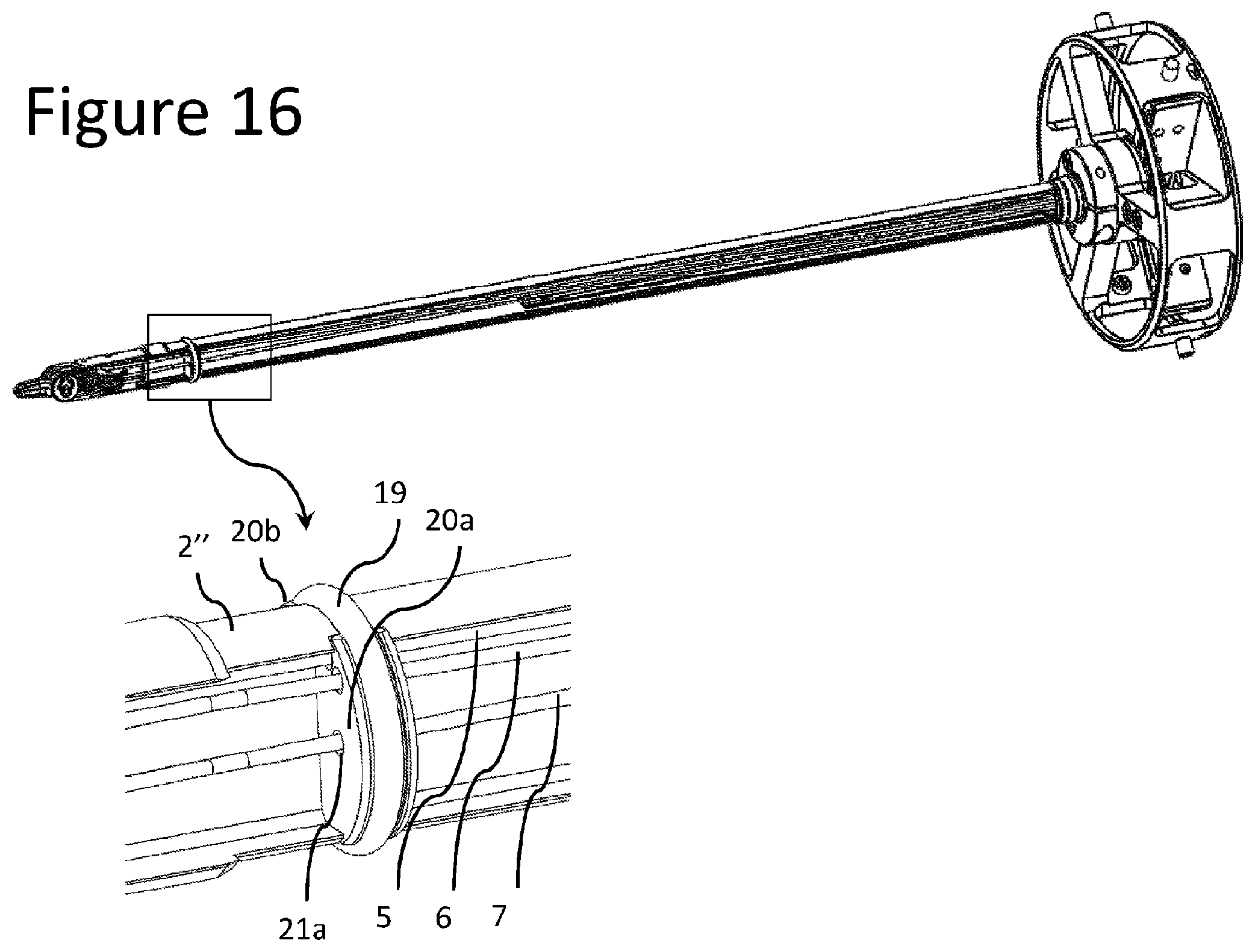
FIG. 16 shows a detailed perspective view of sealing and transversal elements mounted on an internal structural element according to an embodiment of the present invention.
DETAILED DESCRIPTION OF THE INVENTION
A reusable surgical instrument 1 for minimally invasive surgical procedures, with a detachable external tube 2', constructed in accordance with an embodiment of the present invention, is described herein, and is seen generally in FIG. 1. This instrument 1 includes a main shaft 2, a distal articulated end-effector 3 and a proximal hub 4. Referring to FIG. 2, the shaft 2 is composed of two different elements: an internal structural element 2'' and an external tube 2'. The internal structural element 2'' provides a stable positioning to the end-effector 3 and to allow the passage of the different mechanical elements 5, 6, 7 that are able to deliver motion to the different end-effector links 8, 9, 10 from the proximal hub 4 at the proximal extremity of the instrument (FIGS. 3 and 4). The external tube 2' protects the internal elements on the shaft 2 when passing through the incision and avoids the passage of air through the instrument 1, in order to maintain the inflation of the body cavity where the instrument 1 is operating.
Referring still to FIG. 4, the end-effector 3 is connected to the internal structural element 2'' by a proximal joint, which allows the rotation of the proximal end-effector link 8 about the proximal axis 11 in such a manner that the orientation of the proximal end-effector link 8 with respect to the main shaft axis 12 can be changed. The distal end-effector links 9, 10 are rotatably connected to the proximal end-effector link 8 by two distal joints, having coincident axes of rotation, which are represented by the distal axis 13. This distal axis 13 is substantially perpendicular and non-intersecting with the proximal axis 11 and substantially intersects the main shaft axis 12. FIGS. 5 to 9 show the surgical instrument 1 with different angular displacements at the end-effector joints. FIGS. 10 to 12 show the connection between the transmission element 5, 6, 7 and the end-effector links 8, 9, 10.
With reference to FIGS. 13 and 14, the movement is transmitted to each one of the three distal articulations of the instrument 1 by a rotating element 14, 15, 16, which is able to rotate about an axis 17 and is connected to a transmission element 5, 6, 7. As a result, when the rotating element 14, 15, 16 rotates a certain angle .theta.1, .theta.2, .theta.3 about the axis 17, a rotation .alpha.1, .alpha.2, .alpha.3 is transmitted to the respective end-effector member 8, 9, 10.
The external tube 2' can be easily and individually detached and attached to the instrument 1 after each procedure. Referring to FIG. 15, the internal structural element 2'' is fixed directly to the proximal hub 4 and the external tube 2' can be connected and disconnected from the internal structural element 2'' at the threaded surfaces 18a and 18b. Therefore, with this architecture, the external tube 2' can be removed from the instrument 1, without the need to disassemble other parts of the system, like the articulated end-effector 3 or the mechanical transmission elements 5, 6, 7, which remain completely operational from a mechanical perspective without the external tube 2'. This feature facilitates the effective cleaning and sterilization of the instrument 1, which can easily be performed by the hospital staff.
Towards a more distal region of the instrument shaft 2, the external tube 2' is in contact with a sealing element 19, which fills the gap between the internal surface of the external tube 2' and the two transversal elements 20a, 20b that are mounted on the internal structural element 2''. These two transversal elements 20a, 20b have small channels 21a, 21b, 21c, 21d, 21e, 21f through which the transmission elements 5, 6, 7 can pass, guaranteeing the air-tightness of the instrument 1.
In some embodiments of the present invention, the mechanical transmission elements 5, 6, 7 may comprise ropes, whose tension can be released after each procedure, so that the cleaning and sterilization procedures become easier. By releasing the tension on the ropes, the blood and tissue infiltrated amongst the strands of the ropes can be more easily removed. In addition, areas of contact between the ropes and other mechanical elements (like pulleys, end-effector links 8, 9, 10 or rotating elements 14, 15, 16) can be more easily accessed.
While this invention has been shown and described with reference to particular embodiments thereof, it will be understood by those skilled in the art that various changes in form and details may be made therein without departing from the spirit and scope of the invention as defined by the appended claims. For instance, the external tube 2' can be made out of different parts and can be attached to the proximal hub 4. In another embodiment, the internal structural element 2'' can also be composed of different parts and can assume different geometries with diverse cross sections, namely tubular (with openings) or U-shaped.
It will also be easily understood by one of skill in the art that the invention can easily be deployed in the context of other micro-manipulation tasks where complex instruments are used, but regular cleaning and/or sterilization of internal elements of an instrument shaft is desirable. Solely by way of example, micro-manipulation tasks are performed in contaminated environments, wherein thorough cleaning of instrument elements is required after each use. In this context, a detachable outer shaft allowing access to internal elements may be desirable.
* * * * *
References
D00000
D00001
D00002
D00003
D00004
D00005
D00006
D00007
D00008
D00009
D00010
D00011
D00012

D00013
XML
uspto.report is an independent third-party trademark research tool that is not affiliated, endorsed, or sponsored by the United States Patent and Trademark Office (USPTO) or any other governmental organization. The information provided by uspto.report is based on publicly available data at the time of writing and is intended for informational purposes only.
While we strive to provide accurate and up-to-date information, we do not guarantee the accuracy, completeness, reliability, or suitability of the information displayed on this site. The use of this site is at your own risk. Any reliance you place on such information is therefore strictly at your own risk.
All official trademark data, including owner information, should be verified by visiting the official USPTO website at www.uspto.gov. This site is not intended to replace professional legal advice and should not be used as a substitute for consulting with a legal professional who is knowledgeable about trademark law.