Modular hybrid closure
Van Baelen
U.S. patent number 10,637,220 [Application Number 16/073,471] was granted by the patent office on 2020-04-28 for modular hybrid closure. This patent grant is currently assigned to CommScope Connectivity Belgium BVBA. The grantee listed for this patent is COMMSCOPE CONNECTIVITY BELGIUM BVBA. Invention is credited to David Jan Irma Van Baelen.


View All Diagrams
| United States Patent | 10,637,220 |
| Van Baelen | April 28, 2020 |
Modular hybrid closure
Abstract
A hybrid cable distribution system wherein a feeder cable is received by a box. The feeder cable can be a hybrid cable including optical fibers and copper wire (coax). The box may be used only for copper signal handling (such as coaxial signal handling), and then at a later date, the box may be used for receiving fiber signals. Customers can directly connect to the feeder fan out device by connecting a tail of a drop splice module that is spliced to an individual distribution cable to the feeder fan out device. This connection creates a point-to-point connection. The number of fan out devices in the system can be increased or decreased as needed. Alternatively, a splitter input can be connected to the feeder fan out device, such as through a pigtail extending from the splitter, wherein the splitter splits the signal as desired into a plurality of outputs. The outputs of the splitters can be in the form of connectors or adapters. The connectors or adapters are then connected to tails of drop splice modules that are spliced to individual distribution cables so that customers can receive a split signal. The cable distribution system allows for mixing of connection types to the customer(s) such as a direct connection (point-to-point), or a split signal connection. Further, the types of splitters can be mixed and varied as desired. Further, the types of fan out devices can be mixed and varied as desired.
| Inventors: | Van Baelen; David Jan Irma (Winksele, BE) | ||||||||||
|---|---|---|---|---|---|---|---|---|---|---|---|
| Applicant: |
|
||||||||||
| Assignee: | CommScope Connectivity Belgium
BVBA (Kessel-Lo, BE) |
||||||||||
| Family ID: | 57914979 | ||||||||||
| Appl. No.: | 16/073,471 | ||||||||||
| Filed: | January 30, 2017 | ||||||||||
| PCT Filed: | January 30, 2017 | ||||||||||
| PCT No.: | PCT/EP2017/051908 | ||||||||||
| 371(c)(1),(2),(4) Date: | July 27, 2018 | ||||||||||
| PCT Pub. No.: | WO2017/129815 | ||||||||||
| PCT Pub. Date: | August 03, 2017 |
Prior Publication Data
| Document Identifier | Publication Date | |
|---|---|---|
| US 20190036316 A1 | Jan 31, 2019 | |
Related U.S. Patent Documents
| Application Number | Filing Date | Patent Number | Issue Date | ||
|---|---|---|---|---|---|
| 62288267 | Jan 28, 2016 | ||||
| Current U.S. Class: | 1/1 |
| Current CPC Class: | G02B 6/4454 (20130101); G02B 6/4444 (20130101); G02B 6/4472 (20130101); G02B 6/445 (20130101); H02G 3/086 (20130101); H02G 15/085 (20130101); H02G 3/16 (20130101); H02G 15/113 (20130101); H02G 3/083 (20130101); G02B 6/4451 (20130101); H02G 3/088 (20130101); G02B 6/4477 (20130101); G02B 6/4416 (20130101); G02B 6/4466 (20130101) |
| Current International Class: | H02G 3/08 (20060101); H02G 15/113 (20060101); G02B 6/44 (20060101); H02G 3/16 (20060101); H02G 15/08 (20060101) |
References Cited [Referenced By]
U.S. Patent Documents
| 4650933 | March 1987 | Benda et al. |
| 4768961 | September 1988 | Lau |
| 4770639 | September 1988 | Lau |
| 4797114 | January 1989 | Lau |
| 4820200 | April 1989 | Lau |
| 4840568 | June 1989 | Burroughs et al. |
| 5189410 | February 1993 | Kosugi et al. |
| 5199878 | April 1993 | Dewey et al. |
| 5214673 | May 1993 | Morgenstern et al. |
| 5317663 | May 1994 | Beard et al. |
| 5339379 | August 1994 | Kutsch et al. |
| 5363465 | November 1994 | Korkowski et al. |
| 5393249 | February 1995 | Morgenstern et al. |
| 5432875 | July 1995 | Korkowski et al. |
| 5467062 | November 1995 | Burroughs |
| 5497444 | March 1996 | Wheeler |
| 5582525 | December 1996 | Louwagie et al. |
| 5613030 | March 1997 | Hoffer et al. |
| 5627925 | May 1997 | Alferness et al. |
| 5685741 | November 1997 | Dewey et al. |
| 5694511 | December 1997 | Pimpinella et al. |
| 5701380 | December 1997 | Larson et al. |
| 5717810 | February 1998 | Wheeler |
| 5740298 | April 1998 | Macken et al. |
| 5768463 | June 1998 | Foss et al. |
| 5946440 | August 1999 | Puetz |
| 6061492 | May 2000 | Strause et al. |
| 6116961 | September 2000 | Henneberger et al. |
| 6208796 | March 2001 | Williams Vigliaturo |
| 6226111 | May 2001 | Chang et al. |
| 6263136 | July 2001 | Jennings et al. |
| 6307998 | October 2001 | Williams Vigliaturo |
| 6328608 | December 2001 | Olson et al. |
| 6363183 | March 2002 | Koh |
| 6370294 | April 2002 | Pfeiffer et al. |
| 6418262 | July 2002 | Puetz et al. |
| 6424781 | July 2002 | Puetz et al. |
| 6427035 | July 2002 | Mahony |
| 6507691 | January 2003 | Hunsinger |
| 6511330 | January 2003 | Norris |
| 6532332 | March 2003 | Solheid et al. |
| 6535682 | March 2003 | Puetz et al. |
| 6554652 | April 2003 | Musolf et al. |
| 6556738 | April 2003 | Pfeiffer et al. |
| 6556763 | April 2003 | Puetz et al. |
| 6579014 | June 2003 | Melton et al. |
| 6591051 | July 2003 | Solheid et al. |
| 6599024 | July 2003 | Zimmel |
| 6614953 | September 2003 | Strasser et al. |
| 6616459 | September 2003 | Norris |
| 6632106 | October 2003 | Musolf et al. |
| RE38311 | November 2003 | Wheeler |
| 6647197 | November 2003 | Marrs et al. |
| 6668108 | December 2003 | Helkey et al. |
| 6688780 | February 2004 | Duran |
| 6719382 | April 2004 | Sucharczuk et al. |
| 6760531 | July 2004 | Solheid et al. |
| 6761594 | July 2004 | Johnsen et al. |
| 6792191 | September 2004 | Clapp, Jr. et al. |
| 6810193 | October 2004 | Mueller |
| 6822874 | November 2004 | Marler |
| 6824312 | November 2004 | McClellan et al. |
| 6830465 | December 2004 | Norris et al. |
| 6832035 | December 2004 | Daoud et al. |
| 6848952 | February 2005 | Norris |
| 6850685 | February 2005 | Tinucci et al. |
| 6863446 | March 2005 | Ngo |
| 6885798 | April 2005 | Zimmel |
| 6890187 | May 2005 | Norris |
| 6937807 | August 2005 | Franklin et al. |
| 6983095 | January 2006 | Reagan et al. |
| 7029322 | April 2006 | Ernst et al. |
| 7118284 | October 2006 | Nakajima et al. |
| 7142764 | November 2006 | Allen et al. |
| 7149398 | December 2006 | Solheid et al. |
| 7190874 | March 2007 | Barth et al. |
| 7194181 | March 2007 | Holmberg et al. |
| 7218827 | May 2007 | Vongseng et al. |
| 7218828 | May 2007 | Feustel et al. |
| 7233731 | June 2007 | Solheid et al. |
| 7303220 | December 2007 | Zellak |
| 7310474 | December 2007 | Kanasaki et al. |
| 7333606 | February 2008 | Swam et al. |
| 7333706 | February 2008 | Parikh |
| 7346254 | March 2008 | Kramer et al. |
| 7376322 | May 2008 | Zimmel et al. |
| 7376323 | May 2008 | Zimmel |
| 7400813 | July 2008 | Zimmel |
| 7418181 | August 2008 | Zimmel et al. |
| 7418184 | August 2008 | Gonzales |
| 7453706 | November 2008 | Clark et al. |
| 7470068 | December 2008 | Kahle et al. |
| 7495931 | February 2009 | Clark et al. |
| 7509016 | March 2009 | Smith et al. |
| 7536075 | May 2009 | Zimmel |
| 7593617 | September 2009 | Klunder et al. |
| 7606459 | October 2009 | Zimmel et al. |
| 7636507 | December 2009 | Lu et al. |
| 7697812 | April 2010 | Parikh et al. |
| 7706656 | April 2010 | Zimmel |
| 7751673 | July 2010 | Anderson et al. |
| 7760984 | July 2010 | Solheid et al. |
| 7816602 | October 2010 | Landry et al. |
| 7835611 | November 2010 | Zimmel |
| 7853112 | December 2010 | Zimmel et al. |
| 7885505 | February 2011 | Zimmel |
| 7912336 | March 2011 | Zimmel |
| 8019191 | September 2011 | Laurisch |
| 8023791 | September 2011 | Zimmel et al. |
| 8086084 | December 2011 | Bran de Leon et al. |
| 8107816 | January 2012 | Bolster et al. |
| 8121457 | February 2012 | Zimmel et al. |
| 8180192 | May 2012 | Zimmel |
| 8189983 | May 2012 | Brunet et al. |
| 8297708 | October 2012 | Mizobata et al. |
| 8331753 | December 2012 | Zimmel et al. |
| 8340491 | December 2012 | Zimmel |
| 8346045 | January 2013 | Zimmel et al. |
| 8488934 | July 2013 | Zhou et al. |
| 8494329 | July 2013 | Nhep et al. |
| 8520997 | August 2013 | Zimmel |
| 8542972 | September 2013 | Zimmel |
| 8554044 | October 2013 | Bran de Leon |
| 8577198 | November 2013 | Solheid et al. |
| 8634689 | January 2014 | Zimmel |
| 8660429 | February 2014 | Bolster et al. |
| 8705928 | April 2014 | Zimmel et al. |
| 8774585 | July 2014 | Kowalczyk |
| 8798428 | August 2014 | Zimmel et al. |
| 8929708 | January 2015 | Pimentel et al. |
| 9146371 | September 2015 | Zimmel |
| 9197346 | November 2015 | Bolster et al. |
| 9213159 | December 2015 | Zimmel et al. |
| 9239442 | January 2016 | Zhang |
| 9274285 | March 2016 | Courchaine et al. |
| 9335504 | May 2016 | Solheid et al. |
| 9417401 | August 2016 | Zhang |
| 9494760 | November 2016 | Simmons |
| 9563017 | February 2017 | Zimmel et al. |
| 9678292 | June 2017 | Landry et al. |
| 10031305 | July 2018 | Leeman et al. |
| 2004/0175090 | September 2004 | Vastmans |
| 2005/0053341 | March 2005 | Zimmel |
| 2005/0129379 | June 2005 | Reagan et al. |
| 2005/0232551 | October 2005 | Chang et al. |
| 2005/0232565 | October 2005 | Heggestad et al. |
| 2006/0008231 | January 2006 | Reagan et al. |
| 2006/0228086 | October 2006 | Holmberg et al. |
| 2007/0036503 | February 2007 | Solheid et al. |
| 2007/0147765 | June 2007 | Gniadek et al. |
| 2007/0165995 | July 2007 | Reagan et al. |
| 2007/0189691 | August 2007 | Barth et al. |
| 2007/0189692 | August 2007 | Zimmel et al. |
| 2008/0031585 | February 2008 | Solheid et al. |
| 2008/0079341 | April 2008 | Anderson et al. |
| 2008/0124038 | May 2008 | Kowalczyk et al. |
| 2008/0175550 | July 2008 | Coburn et al. |
| 2009/0022468 | January 2009 | Zimmel |
| 2009/0060440 | March 2009 | Wright et al. |
| 2009/0067802 | March 2009 | Hoehne et al. |
| 2009/0103879 | April 2009 | Tang et al. |
| 2009/0110359 | April 2009 | Smith |
| 2009/0263097 | October 2009 | Solheid et al. |
| 2009/0290842 | November 2009 | Bran de Leon et al. |
| 2009/0317047 | December 2009 | Smith et al. |
| 2009/0324187 | December 2009 | Wakileh et al. |
| 2010/0129030 | May 2010 | Giraud et al. |
| 2010/0226654 | September 2010 | Smith et al. |
| 2010/0322580 | December 2010 | Beamon et al. |
| 2010/0329623 | December 2010 | Smith et al. |
| 2010/0329624 | December 2010 | Zhou |
| 2011/0026894 | February 2011 | Rudenick et al. |
| 2011/0058785 | March 2011 | Solheid et al. |
| 2011/0091170 | April 2011 | Bran de Leon |
| 2011/0164853 | July 2011 | Corbille |
| 2011/0211799 | September 2011 | Conner |
| 2011/0262095 | October 2011 | Fabrykowski et al. |
| 2011/0274403 | November 2011 | LeBlanc et al. |
| 2011/0293235 | December 2011 | Nieves et al. |
| 2012/0027355 | February 2012 | LeBlanc et al. |
| 2013/0114930 | May 2013 | Smith et al. |
| 2013/0114937 | May 2013 | Zimmel et al. |
| 2013/0170810 | July 2013 | Badar et al. |
| 2013/0243386 | September 2013 | Pimentel |
| 2014/0219622 | August 2014 | Coan et al. |
| 2014/0334790 | November 2014 | Zhang |
| 2015/0110442 | April 2015 | Zimmel et al. |
| 2015/0137461 | May 2015 | Coenegracht et al. |
| 2015/0241654 | August 2015 | Allen |
| 2015/0286023 | October 2015 | Van Baelen et al. |
| 2015/0301301 | October 2015 | Mullaney |
| 2015/0355428 | December 2015 | Leeman et al. |
| 2016/0370551 | December 2016 | Hill et al. |
| 2017/0097486 | April 2017 | Barrantes |
| 2017/0123175 | May 2017 | Van Baelen et al. |
| 2017/0153407 | June 2017 | Van Baelen et al. |
| 2019/0056559 | February 2019 | Leeman et al. |
| 2008264211 | Jan 2009 | AU | |||
| 203101690 | Jul 2013 | CN | |||
| 103238095 | Aug 2013 | CN | |||
| 41 30 706 | Mar 1993 | DE | |||
| 42 29 510 | Mar 1994 | DE | |||
| 202 01 170 | May 2002 | DE | |||
| 103 50 954 | May 2005 | DE | |||
| 10 2009 008 068 | Aug 2010 | DE | |||
| 0 730 177 | Sep 1996 | EP | |||
| 0 828 356 | Mar 1998 | EP | |||
| 1 092 996 | Apr 2001 | EP | |||
| 1 107 031 | Jun 2001 | EP | |||
| 1 179 745 | Feb 2002 | EP | |||
| 1 473 578 | Nov 2004 | EP | |||
| 1 626 300 | Feb 2006 | EP | |||
| 2 434 317 | Mar 2012 | EP | |||
| 2 300 978 | Nov 1996 | GB | |||
| 2007-121398 | May 2007 | JP | |||
| 2010-122597 | Jun 2010 | JP | |||
| 96/36896 | Nov 1996 | WO | |||
| 00/07053 | Feb 2000 | WO | |||
| 00/75706 | Dec 2000 | WO | |||
| 02/099528 | Dec 2002 | WO | |||
| 02/103429 | Dec 2002 | WO | |||
| 03/093889 | Nov 2003 | WO | |||
| 2005/045487 | May 2005 | WO | |||
| 2006/127397 | Nov 2006 | WO | |||
| 2010/040256 | Apr 2010 | WO | |||
| 2010/134157 | Nov 2010 | WO | |||
| 2012/074688 | Jun 2012 | WO | |||
| 2012/112344 | Aug 2012 | WO | |||
| 2013/117598 | Aug 2013 | WO | |||
| 2015/193384 | Dec 2015 | WO | |||
| 2016/066780 | May 2016 | WO | |||
Other References
|
ADC Telecommunications, Inc., "DSX-3 Digital Signal Cross-Connect (DSX3) System Application Guide," Document No. ADCP-80-323, 1st Edition, Issue 2, Dec. 1996, p. 1-10; p. 1-11. cited by applicant . ADC Telecommunications, Inc., "DSX-1 Digital Signal Cross Connect PIX-DSX-1--Fifth Edition," dated Oct. 1994, 36 Pages. cited by applicant . ADC Telecommunications, Inc., "DSX-3 Digital Signal Cross-Connect, Front and Rear Cross-Connect Products, 2nd Edition," Doc. No. 274, dated Oct. 2004, 65 pages. cited by applicant . ADC Telecommunications, Inc., OmniReach FTTP Solutions, Doc. No. 1276550, dated May 2004, 12 pages. cited by applicant . ADC Telecommunications, Inc., "PxPIus.TM. DS1 Digital Signal Cross-Connect," dated Jan. 1997, 12 pages. cited by applicant . AFLGlobal: "LGX Optical Coupler Modules" May 17, 2012 XP002744968 retrieved from the Internet: URL.https://web.archive.org/web/20120517022939/http://www.aflglobal.com/P- roducts/Fiber-Inside-Plant/Couplers-Splitters/Optical-Coupler-Modules.aspx- . cited by applicant . International Search Report and Written Opinion for Application No. PCT/EP2013/077292 dated May 28, 2014. cited by applicant . International Search Report and Written Opinion for Application No. PCT/EP2015/063620 dated Feb. 5, 2016. cited by applicant . International Search Report and Written Opinion for Application No. PCT/EP2016/079513 dated Mar. 3, 2017. cited by applicant . International Search Report and Written Opinion of the International Searching Authority for International Patent Application No. PCT/EP2017/051908 dated Jul. 18, 2017, 19 pages. cited by applicant. |
Primary Examiner: Cunningham; Xanthia C
Attorney, Agent or Firm: Merchant & Gould P.C.
Parent Case Text
CROSS-REFERENCE TO RELATED APPLICATION
This application is a National Stage Application of PCT/EP2017/051908, filed on Jan. 30, 2017, which claims the benefit of U.S. Patent Application Ser. No. 62/288,267, filed on Jan. 28, 2016, the disclosures of which are incorporated herein by reference in their entireties. To the extent appropriate, a claim of priority is made to each of the above disclosed applications.
Claims
What is claimed is:
1. A telecommunications enclosure comprising: an outer shell having a first half and a second half; and a base tray positioned within at least one of the first and second halves of the outer shell, the base tray including: a first storage location for receiving at least one splice tray, the splice tray being connectable to a feeder cable; a second storage location for receiving a plurality of fan out modules and/or a plurality of splitter modules; and a third storage location for receiving at least one drop splice module, the at least one drop splice module being connectable to a distribution cable.
2. The telecommunications enclosure of claim 1, further comprising a seal block having passages therethrough, the passages being sized and shaped for feeder cables and distribution cables.
3. The telecommunications enclosure of claim 2, wherein the seal is a gel seal.
4. The telecommunications enclosure of claim 1, wherein the enclosure is environmentally sealable.
5. The telecommunications enclosure of claim 4, wherein the enclosure is sealed to IP68 standards.
6. The telecommunications enclosure of claim 1, wherein the enclosure includes at least one fan out module, wherein the at least one splice tray is spliced to the fan out device, and wherein the at least one drop splice module connects to the fan out device to provide at least one point-to-point connection.
7. The telecommunications enclosure of claim 1, wherein the enclosure includes at least one splitter module and at least one fan out device, the at least one splice tray being spliced to the fan out device and the at least splitter module being connected to an output of the fan out device, the at least one drop splice module connecting to the at least one splitter module output of the at least one splitter module to provide at least one split connection.
8. The telecommunications enclosure of claim 1, wherein the enclosure includes a plurality of drop splice modules each being hingedly connected to the tray.
9. The telecommunications enclosure of claim 8, wherein the drop splice modules are arranged in slots on the tray.
10. The telecommunications enclosure of claim 1, wherein the enclosure includes a plurality of fan out modules, wherein the plurality of fan out modules are stacked on top of one another.
11. The telecommunications enclosure of claim 1, wherein the enclosure includes a plurality of splitter modules, wherein the plurality of splitter modules are stacked on top of one another.
12. The telecommunications enclosure of claim 1, further comprising a seal positioned between the first half and the second half of the outer shell.
13. The telecommunications enclosure of claim 1, further comprising a coaxial splitter attached to the enclosure, wherein the coaxial splitter is configured to split a single coaxial signal into a plurality of output split signals.
14. The telecommunications enclosure of claim 1, wherein the enclosure includes mounting features that are configured to mount the enclosure to at least one of an outdoor pole, an interior wall surface, an exterior wall surface, a pedestal mount, an underground surface, and a cabinet.
15. The telecommunications enclosure of claim 1, wherein the base tray includes a fourth storage location for receiving and storing excess cabling.
16. The telecommunications enclosure of claim 1, wherein the base tray includes at least one splice tray spliced to a feeder cable, and wherein the at least one splice tray of a first enclosure has an output connected to an at least one fan out device of a second enclosure.
17. A telecommunications enclosure comprising: an outer shell having a first half and a second half; a base tray positioned within at least one of the first and second halves of the outer shell, the base tray including: at least one splice tray, the splice tray being connected to a feeder cable; at least one fan out module connected to the at least one splice tray; at least one splitter module connected to an output of the at least one fan out module; and at least one drop splice module, the at least one drop splice module being connected to a distribution cable and being connectable to an output of the splitter module or an output of the at least one fan out module to provide a point-to-point connection or a split output.
18. The telecommunications enclosure of claim 17, wherein the enclosure includes a plurality of drop splice modules each being hingedly connected to the tray.
19. The telecommunications enclosure of claim 17, wherein the at least one drop splice module is arranged in a slot on the tray.
20. The telecommunications enclosure of claim 17, wherein the enclosure includes a plurality of fan out modules, wherein the plurality of fan out modules are stacked on top of one another.
21. The telecommunications enclosure of claim 17, wherein the enclosure includes a plurality of splitter modules, wherein the plurality of splitter modules are stacked on top of one another.
22. The telecommunications enclosure of claim 17, further comprising a seal block having passages therethrough, the seal block being positioned between the first and second halves of the outer shell, the passages being sized and shaped for at least one feeder cable and at least one distribution cable.
23. The telecommunications enclosure of claim 22, wherein the seal is a gel seal.
24. The telecommunications enclosure of claim 17, wherein the enclosure is environmentally sealable.
25. The telecommunications enclosure of claim 24, wherein the enclosure is sealed to IP68 standards.
26. The telecommunications enclosure of claim 17, wherein the drop splice module includes: an input pig-tail attached to a main body; a splice area disposed on the main body; and a cable fixation area configured for connection to a distribution cable.
27. The telecommunications enclosure of claim 26, further including a cover configured to enclose the splice area.
28. The telecommunications enclosure of claim 27, wherein the cover is translucent.
29. The telecommunications enclosure of claim 26, wherein the splice area has a plurality of splice positions so as to be configured to allow at least two fibers per distribution cable.
30. The telecommunications enclosure of claim 26, wherein the splice area provides storage for overlength fibers.
31. The telecommunications enclosure of claim 26, further comprising an enclosure fixation fin extending from the main body, wherein the enclosure fixation fin is configured to interface with an enclosure.
32. The telecommunications enclosure of claim 26, further comprising a yarn fixation portion configured to hold excess aramid yard around a spool.
Description
BACKGROUND
As demand for telecommunications increases, networks are being extended in more and more areas. In facilities such as single family homes, multiple dwelling units (MDU's), apartments, condominiums, businesses, etc., boxes are used to provide subscriber access points to a telecommunications network. Cables are also used to interconnect the subscriber access points provided by boxes with subscribers at subscriber locations (e.g., at each residence).
Various boxes for telecommunications equipment are known. The boxes used for subscriber access points can have various forms depending on such factors as the environment, the space requirements for containing telecommunications equipment, and the type of technician access needed for the telecommunications equipment. These and other considerations are related to box design and usability. There is a continued need for improvement in box designs.
SUMMARY
A hybrid cable distribution system is provided wherein a feeder cable is received by a box. The feeder cable can be a hybrid cable including optical fibers and copper wire (coax). In one example, in accordance with the present disclosure, the box may be used only for copper signal handling (such as coaxial signal handling), and then at a later date, the box may be used for receiving fiber signals.
The box can include a copper-splitter mounted to the outside for splitting a coaxial signal. Inside the box, fibers from the feeder cable are spliced to a feeder fan out device. Customers can directly connect to the feeder fan out device by connecting a tail of a drop splice module that is spliced to an individual distribution cable to the feeder fan out device. This connection creates a point-to-point connection. The number of fan out devices in the system can be increased or decreased as needed. Alternatively, a splitter input can be connected to the feeder fan out device, such as through a pigtail extending from the splitter, wherein the splitter splits the signal as desired into a plurality of outputs. The outputs of the splitters can be in the form of connectors or adapters. The connectors or adapters are then connected to tails of drop splice modules that are spliced to individual distribution cables so that customers can receive a split signal.
The cable distribution system allows for mixing of connection types to the customer(s) such as a direct connection (point-to-point), or a split signal connection. Further, the types of splitters can be mixed and varied as desired, such as 1:4, 1:8, 1:16, etc., or other. Further, the types of fan out devices can be mixed and varied as desired, such as fan out devices having 8, 16, outputs, etc., or other. Other combinations are possible.
The fan out devices and splitters can be stored within the box in a vertical or horizontal stacking arrangement. In such an arrangement, the fan out devices and splitters can be stacked on top of one another, or next to one another, in an internal tray. The tray can be secured to a base of a box. The tray is also configured to hold a plurality drop splice modules and a plurality of splice trays for splicing a feeder cable.
The fan out devices, splitters, and drop splice modules can be stored in an environmental resistant box. For example, the box can have a lid and a base including a seal therebetween. Further, the box can include a gel seal to provide a watertight seal for all cables entering and exiting the box. In some embodiments, the box is rated at IP54 and in other embodiments, the box is rated at IP68.
The inputs and outputs of the splitters and fan out devices can be in the form of connectors or adapters mounted at or within the device housings, or connectors or adapters on the ends of stubs extending from the housings. The stubs (semi-rigid) can improve density and improve connector and/or adapter access through movement of the stubs. Preferably, the stubs are not so flexible that the stubs become easily tangled up with each other.
The connectors and adapters utilized in the cable distribution system can be any desired connection type, such as SC type or LC type. MPO types may also be used. Ferrule-less connections may also be used.
Growing capacity may occur where the customer wants more splitters and point-to-point (double density) at the same location. Therefore, the number of fan out devices and splitters can be increased. Alternatively, additional boxes can be interconnected to the initially installed box; a ruggedized fan-out stub of a second box can be spliced to the feeder cable of the initially installed box and routed to the new box, and the new box can be installed similar to the first box. Depending on the feeder cable, more boxes or cabinets can be connected. In another example, growing capacity can occur where the customer wants a second box at a nearby location, such as a somewhere else in the neighborhood.
In one aspect of the present disclosure, a telecommunications enclosure is disclosed. The telecommunications enclosure includes an outer shell that has a first half and a second half. The telecommunications enclosure includes a tray positioned within at least one of the first and second halves of the outer shell. The tray includes a first storage location for receiving at least one splice module. The splice module is connectable to a feeder cable. The tray includes a second storage location for receiving a plurality of fan out modules and/or a plurality of splitter modules. The tray includes a fourth storage location for receiving at least one drop splice module. The at least one drop splice module is connectable to a distribution cable.
In another aspect of the present disclosure, a telecommunications system is disclosed. A telecommunications system includes a first enclosure that has at least one splice module spliced to a feeder cable. The telecommunications system includes a second enclosure that has at least one fan out device. The at least one splice module of the first enclosure has an output connected to the at least one fan out device of the second enclosure.
In another aspect of the present disclosure, a telecommunications enclosure is disclosed. The telecommunications enclosure includes an outer shell that has a first half and a second half. The telecommunications enclosure includes a tray that is positioned within at least one of the first and second halves of the outer shell. The tray includes at least one splice module. The splice module is connected to a feeder cable. The tray includes at least one fan out module connected to the at least one splice module. The tray includes at least one splitter module connected to an output of the at least one fan out module. The tray includes at least one drop splice module. The at least one drop splice module is connected to a distribution cable and is connectable to an output of the splitter module or to an output of the at least one fan out module to provide a point-to-point connection or a split output.
In another aspect of the present disclosure, a telecommunications enclosure is disclosed. The telecommunications enclosure includes an outer shell that has a first half and a second half. The telecommunications enclosure includes a tray that is positioned within at least one of the first and second halves of the outer shell. The tray includes at least one splice module. The splice module is connected to a feeder cable. The tray includes at least one fan out module connected to the at least one splice module. The tray includes at least one drop splice module. The at least one drop splice module is connected to a distribution cable and is connectable to an output of the at least one fan out module to provide a point-to-point connection.
In another aspect of the present disclosure, a telecommunication drop splice cassette is disclosed. The telecommunication drop splice cassette includes an input pig-tail attached to a main body. The telecommunication drop splice cassette includes a splice area that is disposed on the main body and a cable fixation area that is configured for connecting to a distribution cable.
A variety of additional aspects will be set forth in the description that follows. The aspects can relate to individual features and to combinations of features. It is to be understood that both the foregoing general description and the following detailed description are exemplary and explanatory only and are not restrictive of the broad inventive concepts upon which the embodiments disclosed herein are based.
BRIEF DESCRIPTION OF THE DRAWINGS
The following drawings are illustrative of particular embodiments of the present disclosure and therefore do not limit the scope of the present disclosure. The drawings are not to scale and are intended for use in conjunction with the explanations in the following detailed description. Embodiments of the present disclosure will hereinafter be described in conjunction with the appended drawings, wherein like numerals denote like elements.
FIGS. 1-2 show an example telecommunications box in accordance with aspects of the present disclosure, in a closed position.
FIGS. 3-5 show the box opened, with a cover positioned away from a base for access to an interior of the box.
FIG. 6 shows a coax splitter mounted at a bottom of the box and a plurality of distribution cables.
FIGS. 7-8 show the box including mounting features on the outside of the box, and the coax splitter mounted to the base of the box so as not to block fiber access to the box and to allow the cover to freely open.
FIG. 9 shows the coax splitter mounted to the cover of the box.
FIGS. 10-14 show various views of coax splitters, including a 1:4, a 1:8, or a 1:16 splitter; and the option each splitter including a jumper output for connecting other additional splitters, as shown in FIG. 14.
FIGS. 15-16 show the interior of the box when assembled with telecommunications equipment; FIG. 16 shows how each component within the box interacts with one another.
FIG. 17 shows a perspective view of the box opened.
FIG. 18 shows the box equipped for only point-to-point connections.
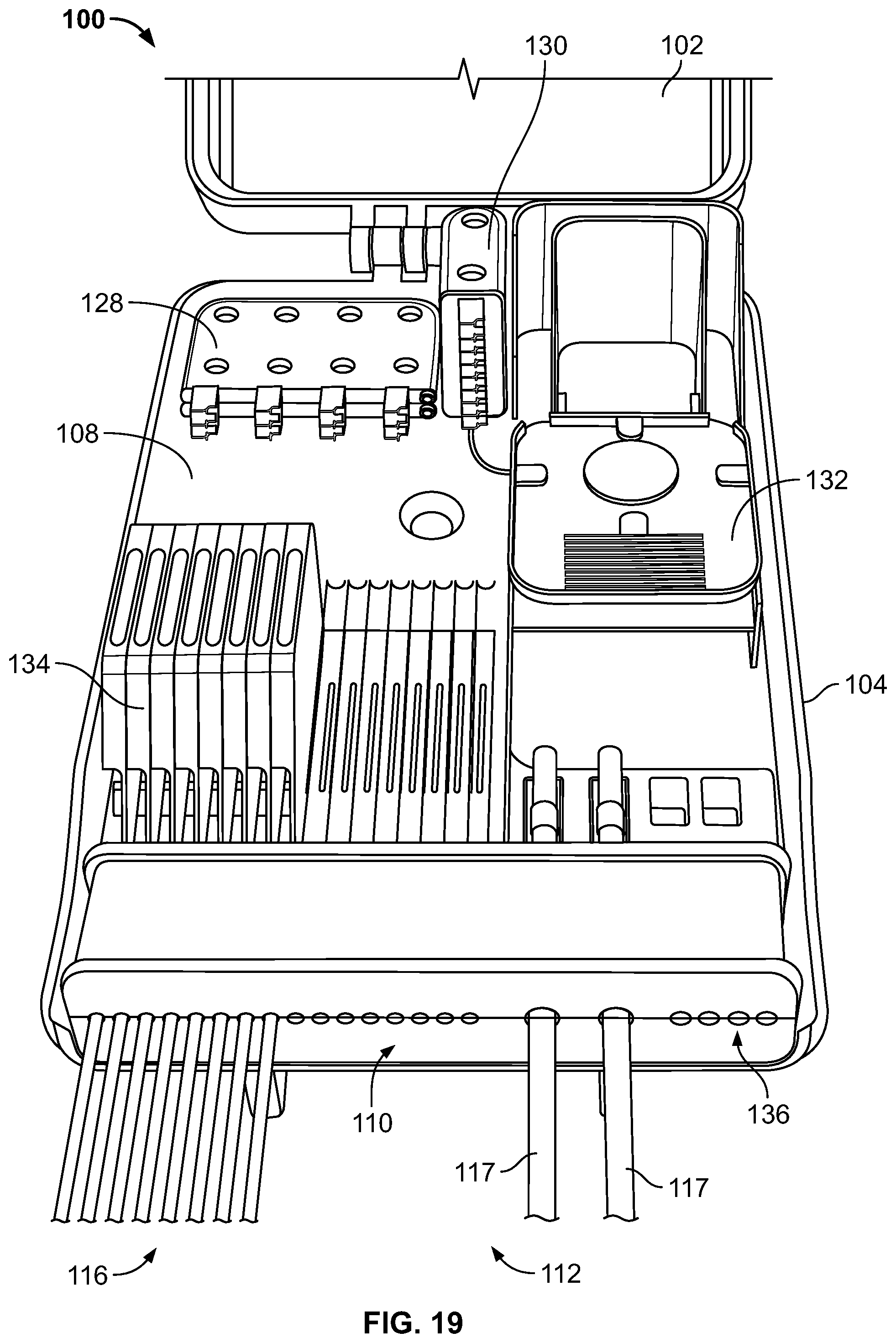
FIGS. 19-22 show examples of the box when configured for split output only; FIG. 19 shows the box configured for eight customers and sealed with a gel seal; FIG. 20 shows the box configured for eight customers and sealed with a gel seal; FIG. 21 shows the box configured for sixteen customers and sealed with a gel seal; FIG. 22 shows the box configured for sixteen customers and does not include a gel seal.
FIGS. 23-25 show examples of the box when configured for point-to-point connections only; FIG. 23 shows the box configured for eight customers and does not include a gel seal; FIG. 24 shows the box configured for eight customers and does not include a gel seal; FIG. 25 shows the box configured for sixteen customers and does not include a gel seal.
FIG. 26 shows a pair of boxes each being configured for sixteen customers a piece, for a total of thirty two customers, with each distribution cable having two fibers.
FIG. 27 shows a centralized solution including five boxes.
FIG. 28 shows the same system, with the boxes distributed from one another (e.g., in a neighborhood).
FIG. 29 shows a pair of boxes each being configured for sixteen customers a piece, for a total of thirty-two customers, with each distribution cable having two fibers.
FIG. 30 shows a centralized solution including three boxes.
FIG. 31 shows the same system, with the boxes distributed from one another (e.g., in a neighborhood).
FIG. 32 shows a chart for various examples of the telecommunications equipment that the box, disclosed herein, can include.
FIGS. 33-34 show a tray, according to one embodiment of the present disclosure.
FIGS. 35-36 show example splitters; FIG. 35 shows a 1:4 splitter; FIG. 36 shows 2.times.1:4, 1.times.1:8, and 1.times.1:16 splitters.
FIG. 37 shows a fan out.
FIG. 38 shows drop splice module.
FIG. 39 shows the drop splice module partially removed from the box.
FIGS. 40-41 show a tray body of the drop splice module.
FIGS. 42-43 show the drop splice module including a seal; a three cable seal is shown in FIG. 42 for illustration purposes.
FIG. 44 shows the box including a riser fan out.
FIGS. 45-46 show the box incorporated into a cabinet solution.
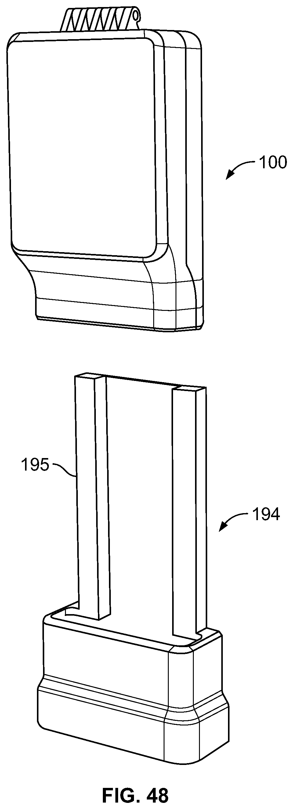
FIGS. 47-50 show the box mounted on a pedestal; in FIG. 49 cable slack can be stored under the pedestal.
FIG. 51 shows a box according to another embodiment of the present disclosure.
DETAILED DESCRIPTION
Various embodiments will be described in detail with reference to the drawings, wherein like reference numerals represent like parts and assemblies throughout the several views. Reference to various embodiments does not limit the scope of the claims attached hereto. Additionally, any examples set forth in this specification are not intended to be limiting and merely set forth some of the many possible embodiments for the appended claims.
Referring now to FIGS. 1-51, a distribution box 100 is shown. Various embodiments of the box 100 are described and shown in the Figures, including an enclosure structure including a base, a cover, and a coax signal splitter for splitting a coaxial signal. The box is configured for use in a variety of different environments. For example, the box can be mounted to a pole outside, on a wall inside or outside, on a pedestal mount, underground within a manhole, or within a cabinet. In the depicted embodiments, a single box can be configured to serve up to thirty-two customers.
Further, the box is configured for use in an environment where it is perceived that a migration from copper wire transmission to fiber optic transmission is imminent. For example, during the initial install, the network may be purely copper wire transmission (coaxial), then transition to a coax/fiber (hybrid) network, and, finally, to a fully fiber optic network.
FIGS. 1 and 2 show the box 100 closed. The box 100 is shown having a cover 102 and a base 104. In the depicted embodiments, the cover is attached via a hinge 106 to the base 104. The box 100 is configured for use indoors and outdoors. In some embodiments, a seal (not shown) exists between the cover 102 and the base 104 allowing the box to be IP54 rated. The box 100 can have a width W of about 24 centimeters, a height H of about 35 centimeters, and a depth of about 13 centimeters.
FIGS. 3-5 shows the box 100 opened, with the cover 102 positioned away from the base 104 for access to the interior of the box 100. Inside the box 100 is a tray 108 for positioning telecommunications equipment. In some embodiments, the tray 108 can be secured to the base 104 by a central screw 109.
Further, a gel seal 110 can be used at an entry 112 of the box 100 for environmentally sealing the interior of the box 100. Depending on the mounting location of the box 100, the gel seal may or may not be included in the box. For example, if installed on a wall indoors, the gel seal 110 may not be installed with the box 100. In some embodiments, the gel seal 110 can be combined with another material such as an elastomer. When a gel seal is used, the box 100, when closed, may be IP68 rated.
The gel of the gel seal 110 can be a soft gel or a generally hard gel. The gel of the gel seal 110 may comprise, for example, silicone gel, urea gel, urethane gel, thermoplastic gel, or any suitable gel or geloid sealing material. Gels are normally substantially incompressible when placed under a compressive force and normally flow and conform to their surroundings, thereby forming sealed contact with other surfaces. Example gels include oil-extended polymers. The polymer may, for example, comprise an elastomer, or a block copolymer having relatively hard blocks and relatively elastomeric blocks. Example copolymers include styrene-butadiene or styrene-isoprene di-block or tri-block copolymers. In still other embodiments, the polymer of the gel may include one or more styrene-ethylene-propylene-styrene block copolymers. Extender oils used in example gels may, for example, be hydrocarbon oils (e.g., paraffinic or naphthenic oils or polypropene oils, or mixtures thereof). The sealing members can also include additives such as moisture scavengers, antioxidants, tackifiers, pigments, and/or fungicides. In certain embodiments, sealing members in accordance with the principles of the present disclosure have ultimate elongations greater than 100 percent with substantially elastic deformation to an elongation of at least 100 percent.
FIGS. 6-7 show the box 100 with a coax splitter 114 and a plurality of distribution cables 116. As shown, each distribution cable 116 enters the box 100 at the entry 112 and is also connected to the coax splitter 114. In some embodiments, the entry 112 can be at the bottom of the box 100, and in other embodiments, the entry can be on a different side of the box 100. Further, a pair of feeder cables 117 is also shown entering the box 100 at an entry 112. As shown in FIG. 7, the box 100 includes mounting features 121 on the outside of the box 100. The mounting features 121 can be used to secure the box 100 to a wall, pole, or other mounting surface. For example, straps can be glided through the mounting features 121 to mount the box 100 to a pole.
The coax splitter 114 is placed on the outside of the box 100 as the coax connections are environmentally resistant, therefore allowing the box 100 footprint to be smaller. The coax splitter 114 splits a single input coax signal into a plurality of output split signals. In some embodiments, the coax splitter 114 is passive and not powered. In some embodiments, the width W of the box 100 is equal to a width of the coax splitter 114. As shown in FIG. 6, the coax splitter 114 can be mounted at a bottom of the box 100. As shown in FIGS. 7-8, the coax splitter 114 is mounted to the base 104 of the box 100 so as not to block fiber access to the box 100 and to allow the cover 102 to freely open. FIG. 9 shows the coax splitter 114 mounted to the cover 102 of the box 100.
The distribution cables 116 can include both a copper cabling (i.e., coax) and optical fibers. In some embodiments, the distribution cables 116 include empty tubing for the optical fibers to be installed at a later date. In other embodiments, the distribution cables 116 can be siamese cables that include a coaxial connector and an over length tube or f-cable at one end. In some embodiments, the coax portion of the distribution cable 116 is removable entirely from the distribution cable 116. In still other embodiments, each distribution cable 116 includes up to four fibers, while only a maximum of two fibers will be used and any additional fibers will be stored.
FIGS. 10-14 show the coax splitter 114. As shown, the coax splitter 114 includes a mounting flange 120, an input 122, a jumper output 124, and a plurality of split outputs 126. A shown in FIGS. 11-13, the coax splitter 114 can be a 1:4, a 1:8, or a 1:16 splitter. Each splitter 114 includes an input 122 and a plurality of split outputs 126. Additionally, each splitter 114 can include a jumper output 124 for connecting other additional splitters, as shown in FIG. 14. The coax splitter 114 can be EMEA certified. In other embodiments, the coax splitter 114 can be of a variety of different sizes. In the depicted embodiment, the coax splitter 114 consists of two rows of connectors.
FIGS. 15-16 show the interior of the box 100 when assembled with telecommunications equipment. Mounted on the tray 108 are at least one splitter 128, a fan out 130, a splice tray 132, and a drop splice module 134. A variety of splitters 128 and fan outs 130 are shown mounted within the box 100. The splitters 128 used are for splitting of the signals of the fanned out feeder fibers at the splice trays 132. Within the interior of the splitter 128, the splitter input is split into a plurality of outputs. The box 100 can hold one or more splitters 128 and fan out devices 130. The preferred box 100 allows for: 1) split outputs of a feeder input cable 117; 2) point-to-point connections with distribution cables 116 via the drop splice modules 134; or 3) both split feeder signals and point-to-point feeder signals.
Each component within the box 100 can be organized within the box 100 so as to allow the system to be customized for particular applications. This allows the user to use similar components for a variety of differently sized applications. The box 100 allows for the later addition of splitters 128 and/or fan outs 130 to delay early cost if the system is small to start. At a later date, if the box 100 needs to expand, splitters and fan-outs can be added. Further, there is no overlength issues with pre-termination distribution cables as all distribution cables 116 are spliced at the drop splice modules 134 within the box 100.
FIG. 16 shows how each component within the box 100 interacts with one another. As shown, feeder cables 117 enter the box 100 via the entry point 112. In some embodiments, the feeder cables 117 pass through the gel seal 110. The feeder cable 117 is then spliced with an input of at least one fan out 130 at the splice tray 132. The inputs of the splitters 128 are then connected to outputs of the fan outs 130. Outputs of the splitters 128 are then connected to the inputs of the drop splice modules 134. Each drop splice module 134 is connected to a single distribution cable allowing for a split output to be sent via the distribution cable 116. When making a point-to-point connection, the inputs of the drop splice modules 134 are connected directly to the output of the fan out 130. Depending on the particular application, the components can be positioned in a variety of different ways within the box 100 on the tray 108.
FIG. 17 shows a perspective view of the box 100 opened. In the depicted embodiment, the box 100 is fully loaded for a purely split output configuration. As shown, two feeder cables 117 are entering the box 100 through the gel seal 110. The gel seal 110 also includes four auxiliary ports 136 for four satellite cables (not shown). Eight splice trays 132 are shown, each having eight splices per tray. The fan out 130 is shown having eight connections, and the splitters 128 are shown having thirty-two connections. There are sixteen drop splice modules 134, each splicing two fibers, for a total of thirty-two total splices.
FIG. 18 shows the box 100 equipped for only point-to-point connections. As shown, four fan outs 130 are connected to four splice trays 132. Each fan out output can be connected to drop splice module 134 input for point-to-point connections.
FIGS. 19-22 show examples of the box 100 when configured for split output only.
FIG. 19 shows the box 100 configured for eight customers and sealed with a gel seal 110 so that the box is rated at IP68. Two splitters 128 are shown and each is configured to be 1:4. As shown, each distribution cable 116 includes one fiber.
FIG. 20 shows the box 100 configured for eight customers and sealed with a gel seal 110 so that the box is rated at IP68. Three splitters 128 are shown. Two splitters are configured to be 1:4, and one splitter is configured to be 1:8. As shown, each distribution cable 116 includes two fibers.
FIG. 21 shows the box 100 configured for sixteen customers and sealed with a gel seal 110 so that the box is rated at IP68. Two splitters 128 are shown and each is configured to be 1:8. As shown, each distribution cable 116 includes one fiber.
FIG. 22 shows the box 100 configured for sixteen customers and does not include a gel seal 110 so that the box is rated at IP54. Two splitters 128 are shown and each is configured to be 1:16. As shown, each distribution cable 116 includes two fibers.
FIGS. 23-25 show examples of the box 100 when configured for point-to-point connections only.
FIG. 23 shows the box 100 configured for eight customers and does not include a gel seal 110 so that the box is rated at IP54. One fan out 130 is shown and is configured to be 1:8. As shown, each distribution cable 116 includes one fiber.
FIG. 24 shows the box 100 configured for eight customers and does not include a gel seal 110 so that the box is rated at IP54. Two fan outs 130 are shown and each is configured to be 1:8. As shown, each distribution cable 116 includes two fibers.
FIG. 25 shows the box 100 configured for sixteen customers and does not include a gel seal 110 so that the box is rated at IP54. Four fan outs 130 are shown and each is configured to be 1:8. As shown, each distribution cable 116 includes two fibers.
FIG. 26 shows a pair of boxes 100, 100' each being configured for 16 customers a piece, for a total of 32 customers, with each distribution cable 116, 116' having two fibers. Further, each box 100, 100' is configured for split outputs. Feeder cables 117 enter the first box 100 and the secondary box 100' can be positioned in either close proximity to, or in the general area of, the first box 100 (e.g., within the neighborhood). A fan out 130' from the second box 100' having a ruggedized stub input 131' exits from the second box 100' and enters through an auxiliary port 136 of the first box 100. Once inside the first box 100, the ruggedized input stub 131' is spliced with the feeder cable 117 at a splice tray 132 in a similar way as the fan out 130 in the first box 100.
FIG. 27 shows a centralized solution including five boxes. As shown, a single primary box 100 is linked to four secondary boxes 100' via inputs 131' from fan outs. In the depicted embodiment, the total capacity for such a system is eighty customers. FIG. 28 shows the same system, with the boxes distributed from one another (e.g., in a neighborhood).
FIG. 29 shows a pair of boxes 100, 100' each being configured for sixteen customers a piece, for a total of thirty-two customers, with each distribution cable 116, 116' having two fibers. Further, each box 100, 100' is configured for point-to-point outputs. Feeder cables 117 enter the first box 100, and the secondary box 100' can be positioned in either close proximity to or in the general area of the first box 100 (e.g., within the neighborhood). Four fan outs 130' from the second box 130', each having ruggedized stub inputs 131' exit from the second box 100' and enter through auxiliary ports 136 of the first box 100. Once inside the first box 100, the input stubs 131' are spliced with the feeder 117 at splice trays 132 in a similar way to the fan outs 130 in the first box 100.
FIG. 30 shows a centralized solution including three boxes. As shown, a single primary box 100 is linked to two secondary boxes 100' via inputs 131' from fan outs. In the depicted embodiment, the total capacity for such a system with three boxes is sixty-four customers. FIG. 31 shows the same system, with the boxes distributed from one another (e.g., in a neighborhood).
FIG. 32 shows a chart for all the telecommunications equipment that the box 100, disclosed here, can include. A left hand vertical column 138 includes desired system characteristics, including the desired environmental rating, the amount of customers, the amount of fibers per customer, and whether the system will be a point-to-point (PtP) or split output (PON) system. Each subsequent column to the right is each individual component of the telecommunications system. Therefore, a user can select a system on the left column and then reference the associated row to the right to determine the amount and type of each component the user will need.
FIGS. 33 and 34 show the tray 108, according to one embodiment of the present disclosure. As shown, the tray 108 is a standalone piece and can be removed and mounted in places other than the box 100 (e.g., a cabinet without a cover). When installing the tray 108 into the box 100, the feeder cables 117 can be installed on the tray 108 first with clips 119. At a backside 140 of the tray 108, any overlength from the feeder cables 117 can be stored.
FIGS. 35 and 36 show example splitters 128. Each splitter 128 includes an input 141 that is connectorized to match an adaptor output on a fan out 130. The splitter 128 shown includes a plurality of outputs 144 spaced so as to allow for the easy connecting and removal of cables. In FIG. 35, a 1:4 splitter is shown. However, other sized splitters 128 can also be used with more outputs or less outputs. FIG. 37 shows 2.times.1:4, 1.times.1:8, and 1.times.1:16 splitters. The splitter outputs 144 can be SC or LC connectors, in addition to multi-fiber connectors, such as MPO connectors. The splitters 128 can include port identifiers, a splitter identifier, and an RFID tag, if desired. The splitter inputs 141 are connected to the outputs of the fan out devices 130, which are spliced to the feeder cable 117. The splitter 128 takes the feeder cables 117 and splits them into splitter outputs. The splitter outputs 144 are shown as fiber optic connectors disposed within a housing 146 of each splitter 128. The housing 146 of each splitter 128 can be configured so that they are interconnectable and stackable, with one side including protrusions 148 and the other side including recesses 150.
FIG. 37 shows the fan out 130. The fan out 130 is configured to receive a signal from the input stub 131 of a feeder cable 117 from which it is spliced. The fan out 130 operates to separate the individual optical fibers of a multi-fiber feeder cable 117 in a manner such that the fibers are not damaged so as to maintain a quality transmission link. As shown, the fan out 130 includes a plurality of outputs 152 spaced so as to allow for the easy connecting and removal of cables. However, the fan out 130 can be configured with more or less outputs. The outputs 152 can be SC or LC connectors, in addition to multi-fiber connectors, such as MPO connectors. The fan out 130 can include port identifiers, a splitter identifier, and an RFID tag, if desired. Each fan out 130 has a housing 154 that is similar to the housing of the splitter 128. The housings 154 are configured so that they are interconnectable and stackable.
FIG. 38 shows the drop splice module 134. The drop splice module 134 includes a tray body 156 and an input 158. A distribution cable 116 is spliced at the tray body 156 with the input 158. The tray body 156 is configured to hold the splice and fit within the box 100. The input 158 can be connectorized so as to be connectable with the outputs of a fan out 130 or outputs of a splitter 128. The drop splice module 134 allows for splicing to be completed out of the box 100, giving the installer flexibility. For example, splicing can be completed in an install vehicle, or at the ground level (in the case where the box 100 is going to be mounted high on a pole). The drop splice module 134 is also suited for use with multi-fiber cabling and blown tubes. In some embodiments, the drop splice module 134 includes a gel seal around the distribution cable 116.
FIG. 39 shows the drop splice module 134 partially removed from the box 100. As shown, the drop splice module 134 is received by a slot 160 in the tray 108. This allows the user to quickly install and remove particular drop splice modules 134. Further, each drop splice module 134 is positioned in a horizontal row so as to allow the installer to freely remove or add drop splice modules 134 without having to move other modules 134. In some embodiments, the drop splice modules 134 can be connected to the tray 108 by a removable hinge. This allows the user to partially pivot the drop splice module 134 away from the tray 108 and box 100 for service.
FIGS. 40 and 41 show the tray body 156 of the drop splice module 134. The tray body 156 includes a cover 162, a splice area 163, a finger lifter 164, a cable fixation area 166, a box fixation fin 168, and a yarn fixation 170. The cover 162 can be configured to enclose the splice area 163, and also be translucent so as to allow the user to maintain a visual confirmation of the splice. The splice area 163 can have two splice positions 172 so as to be configured to allow two fibers per distribution cable 116. Further, the splice area 163 provides storage for overlength of two fibers.
The finger lifter 164 allows the user to easily lift the drop splice module 134 from a seated position on the tray 108. In other embodiments, the finger lifter 164 can be a tab or knob.
The cable fixation area 166 allows the distribution cable 116 to be fixedly secured to the drop splice module 134. In the depicted embodiments the cable fixation area 166 includes flexible protrusions 174 that allow the distribution cable 116 to snap in place and be fixedly held by the tray body 156. In some embodiments, the distribution cables 116 can be secured to the tray body 156 by way of an attachment device such as a clamp or zip-tie. In such an embodiment, the attachment device can pass through a hole 176 in the tray body 156, and be fixed around the distribution cable 116 at the cable fixation area 166.
The box fixation fin 168 is integral to the tray body 156. The fin 168 is configured to mate with the tray 108 of the box, specifically in the slot 160. The fin 168 permits the drop splice module 134 to be properly positioned by the installer and also helps to retain the drop splice module 134 within the box 100.
The yarn fixation portion 170 is configured to hold excess aramid yard around a spool. After being wrapped around the spool, the aramid yarn can be secured by use of a screw.
The drop splice module 134 can include port identifiers, a module identifier, and an RFID tag, if desired.
FIGS. 42 and 43 show the drop splice module 134 including a seal 178. The seal can include a tacky soft-gel portion 180 and a non-tacky hard gel portion 182. A three cable seal is shown in FIG. 42 for illustration purposes. As shown, the drop splice module 134 includes a hard plastic portion 184 surrounding the cable 116. Between the hard plastic portion 184 and the distribution cable 116 is the soft-gel portion 180. Surrounding the hard plastic portion 184 of the drop splice module 134 is hard gel portion 182 that is suitable for re-entry of the drop splice module 134, thereby allowing the installer to remove the drop splice module 134 from the hard gel portion 182 multiple times. In some embodiments, the hard gel portion 182 can be the gel seal 110 in the box 100, as described above.
FIG. 44 shows the box 100 including a riser fan out 186. The riser fan out 186 can combine the outputs of the drop splice modules into a single cable 187. In some embodiments, a single drop splice module having multiple inputs can be used as an alternative to multiple individual drop spice modules 134. Users can also store un-connected customers as fiber-only in an area 188 in an SC splice cassette.
FIGS. 45 and 46 show the box 100 incorporated into a cabinet solution. A cabinet 190 includes multiple boxes 100, 100' and a coax power amplifier 191 mounted to a base 192. The base 192 can have a height H of between about 50 centimeters and about 80 centimeters. The base can also have a width W of about 65 centimeters, and the overall system can have a depth of about 20 centimeters. In the depicted embodiment, the cabinet 190 can service up to thirty-two coax customers and thirty-two fiber customers with up to two fibers per customer. As shown, the boxes 100, 100' can be interlinked with one another, as described above with respect to FIGS. 26-31. The cabinet 190 can also include an entry plate 193 for assuring proper positioning of any input feeder cables and output distribution cables.
The coax amplifier 191 can function to increase the strength of received coax signals to a level that is greater than the signal losses associated with the distribution system. This is to ensure that coax outputs receive proper strength signals.
FIGS. 47-50 show the box 100 mounted on a pedestal 194. The pedestal 194 includes a frame 195 that is configured to accept the box 100. Such an embodiment is especially suited for an application where the box 100 is installed into a system that is purely fiber optic transmission from day one. As shown in FIG. 49, any cable slack can be stored under the pedestal 194. Once installed on the pedestal 194, the box 100 and pedestal 194 can have a height H of about 50 centimeters, a width W of about 24 centimeters, and a depth of about 13 centimeters.
FIG. 51 shows a box 200 according to one embodiment of the present disclosure. As shown, the box 200 receives feeder cables 117 at sides of the box 200, instead of at the bottom of the box, as shown and described above.
As noted, various implementations of the systems are provided for adding capacity over time. One implementation is to add the splitters or fan out devices as needed over time. Another implementation for adding capacity uses two or more boxes. Another implementation for increasing capacity includes adding a second (or more) distribution box at a remote location.
The various embodiments described above are provided by way of illustration only and should not be construed to limit the claims attached hereto. Those skilled in the art will readily recognize various modifications and changes that may be made without following the example embodiments and applications illustrated and described herein, and without departing from the true spirit and scope of the following claims.
PARTS LIST
100 First box 100' Secondary box 102 Cover 104 Base 106 Hinge 108 Tray 109 Central screw 110 Gel seal 112 Entry 114 Coax splitter 116 Distribution cable 116' Distribution cable 117 Feeder cable 119 Clip 120 Mounting flange 121 Mounting feature 122 Input 124 Jumper output 126 Split output 128 Splitter 130 Fan out device 130' Fan out device 131 Input 131' Ruggedized stub input 132 Splice tray 134 Drop splice module 136 Auxiliary port 138 Left hand vertical column 140 Backside of tray 141 Splitter input 144 Splitter output 146 Splitter housing 148 Protrusion 150 Recess 152 Output 154 Fan out housing 156 Tray body 158 Input 160 Slot 162 Cover 163 Splice area 164 Finger lifter 166 Cable fixation area 168 Box fixation fin 170 Yarn fixation 172 Splice position 174 Flexible protrusion 176 Hole 178 Seal 180 Soft gel portion 182 Hard gel portion 184 Hard plastic portion 186 Riser fan out 187 Single cable 188 Fiber-only area 190 Cabinet 191 Coax amplifier 192 Base 193 Entry plate 194 Pedestal 195 Frame 200 Box
* * * * *
References
D00000
D00001
D00002
D00003
D00004
D00005
D00006
D00007
D00008
D00009
D00010
D00011
D00012

D00013

D00014

D00015

D00016

D00017
D00018

D00019

D00020

D00021

D00022

D00023

D00024

D00025

D00026

D00027

D00028

D00029

D00030

D00031

D00032

D00033

D00034

D00035

D00036

D00037

D00038

D00039

D00040

D00041

D00042

D00043

D00044

D00045
D00046

D00047

D00048

XML
uspto.report is an independent third-party trademark research tool that is not affiliated, endorsed, or sponsored by the United States Patent and Trademark Office (USPTO) or any other governmental organization. The information provided by uspto.report is based on publicly available data at the time of writing and is intended for informational purposes only.
While we strive to provide accurate and up-to-date information, we do not guarantee the accuracy, completeness, reliability, or suitability of the information displayed on this site. The use of this site is at your own risk. Any reliance you place on such information is therefore strictly at your own risk.
All official trademark data, including owner information, should be verified by visiting the official USPTO website at www.uspto.gov. This site is not intended to replace professional legal advice and should not be used as a substitute for consulting with a legal professional who is knowledgeable about trademark law.