Heated windshield indicator
Salter , et al.
U.S. patent number 10,631,373 [Application Number 15/153,055] was granted by the patent office on 2020-04-21 for heated windshield indicator. This patent grant is currently assigned to Ford Global Technologies, LLC. The grantee listed for this patent is Ford Global Technologies, LLC. Invention is credited to Paul Kenneth Dellock, Cornel Lewis Gardner, Jennifer Ann Gauthier, Stuart C. Salter.


| United States Patent | 10,631,373 |
| Salter , et al. | April 21, 2020 |
Heated windshield indicator
Abstract
A windshield assembly is provided herein. The windshield assembly includes a windshield having a frit and an indicator thermally coupled to the windshield to visually coincide with the frit and operable to illuminate in order to indicate a relative temperature of the windshield.
| Inventors: | Salter; Stuart C. (White Lake, MI), Dellock; Paul Kenneth (Northville, MI), Gauthier; Jennifer Ann (Fenton, MI), Gardner; Cornel Lewis (Romulus, MI) | ||||||||||
|---|---|---|---|---|---|---|---|---|---|---|---|
| Applicant: |
|
||||||||||
| Assignee: | Ford Global Technologies, LLC
(Dearborn, MI) |
||||||||||
| Family ID: | 59069388 | ||||||||||
| Appl. No.: | 15/153,055 | ||||||||||
| Filed: | May 12, 2016 |
Prior Publication Data
| Document Identifier | Publication Date | |
|---|---|---|
| US 20170332446 A1 | Nov 16, 2017 | |
| Current U.S. Class: | 1/1 |
| Current CPC Class: | H05B 3/84 (20130101); B60K 35/00 (20130101); G02B 27/01 (20130101); B60Q 3/20 (20170201); B60R 16/0231 (20130101); B60K 2370/188 (20190501); B60K 2370/77 (20190501); B60J 1/02 (20130101) |
| Current International Class: | H05B 3/84 (20060101); B60K 35/00 (20060101); G02B 27/01 (20060101); B60Q 3/20 (20170101); B60R 16/023 (20060101); B60J 1/02 (20060101) |
References Cited [Referenced By]
U.S. Patent Documents
| 2486859 | November 1949 | Meijer et al. |
| 5053930 | October 1991 | Benavides |
| 5434013 | July 1995 | Fernandez |
| 5649377 | July 1997 | Lobner |
| 5709453 | January 1998 | Krent et al. |
| 5839718 | November 1998 | Hase et al. |
| 6028291 | February 2000 | Heisler |
| 6031511 | February 2000 | DeLuca et al. |
| 6037573 | March 2000 | Arsenault et al. |
| 6117362 | September 2000 | Yen et al. |
| 6294990 | September 2001 | Knoll et al. |
| 6419854 | July 2002 | Yocom et al. |
| 6494490 | December 2002 | Trantoul |
| 6577073 | June 2003 | Shimizu et al. |
| 6729738 | May 2004 | Fuwausa et al. |
| 6737964 | May 2004 | Samman et al. |
| 6773129 | August 2004 | Anderson, Jr. et al. |
| 6820888 | November 2004 | Griffin |
| 6851840 | February 2005 | Ramamurthy et al. |
| 6859148 | February 2005 | Miller |
| 6871986 | March 2005 | Yamanaka et al. |
| 6953536 | October 2005 | Yen et al. |
| 6990922 | January 2006 | Ichikawa et al. |
| 7015893 | March 2006 | Li et al. |
| 7161472 | January 2007 | Strumolo et al. |
| 7213923 | May 2007 | Liu et al. |
| 7216997 | May 2007 | Anderson, Jr. |
| 7249869 | July 2007 | Takahashi et al. |
| 7264366 | September 2007 | Hulse |
| 7264367 | September 2007 | Hulse |
| 7347576 | March 2008 | Wang et al. |
| 7441914 | October 2008 | Palmer et al. |
| 7501749 | March 2009 | Takeda et al. |
| 7575349 | August 2009 | Bucher et al. |
| 7635212 | December 2009 | Seidler |
| 7638874 | December 2009 | Chui et al. |
| 7726856 | June 2010 | Tsutsumi |
| 7745818 | June 2010 | Sofue et al. |
| 7753541 | July 2010 | Chen et al. |
| 7830267 | November 2010 | Veerasamy |
| 7834548 | November 2010 | Jousse et al. |
| 7862220 | January 2011 | Cannon et al. |
| 7987030 | July 2011 | Flores et al. |
| 8016465 | September 2011 | Egerer et al. |
| 8022818 | September 2011 | la Tendresse et al. |
| 8044415 | October 2011 | Messere et al. |
| 8066416 | November 2011 | Bucher |
| 8071988 | December 2011 | Lee et al. |
| 8097843 | January 2012 | Agrawal et al. |
| 8118441 | February 2012 | Hessling |
| 8120236 | February 2012 | Auday et al. |
| 8136425 | March 2012 | Bostick |
| 8163201 | April 2012 | Agrawal et al. |
| 8169131 | May 2012 | Murazaki et al. |
| 8178852 | May 2012 | Kingsley et al. |
| 8197105 | June 2012 | Yang |
| 8203260 | June 2012 | Li et al. |
| 8207511 | June 2012 | Bortz et al. |
| 8232533 | July 2012 | Kingsley et al. |
| 8247761 | August 2012 | Agrawal et al. |
| 8261686 | September 2012 | Birman et al. |
| 8286378 | October 2012 | Martin et al. |
| 8317329 | November 2012 | Seder et al. |
| 8317359 | November 2012 | Harbers et al. |
| 8408766 | April 2013 | Wilson et al. |
| 8415642 | April 2013 | Kingsley et al. |
| 8421811 | April 2013 | Odland et al. |
| 8459832 | June 2013 | Kim |
| 8466438 | June 2013 | Lambert et al. |
| 8519359 | August 2013 | Kingsley et al. |
| 8519362 | August 2013 | Labrot et al. |
| 8539702 | September 2013 | Li et al. |
| 8552848 | October 2013 | Rao et al. |
| 8606430 | December 2013 | Seder et al. |
| 8624716 | January 2014 | Englander |
| 8631598 | January 2014 | Li et al. |
| 8653553 | February 2014 | Yamazaki et al. |
| 8664624 | March 2014 | Kingsley et al. |
| 8683722 | April 2014 | Cowan |
| 8724054 | May 2014 | Jones |
| 8754426 | June 2014 | Marx et al. |
| 8773012 | July 2014 | Ryu et al. |
| 8846184 | September 2014 | Agrawal et al. |
| 8851694 | October 2014 | Harada |
| 8876352 | November 2014 | Robbins et al. |
| 8905610 | December 2014 | Coleman et al. |
| 8952341 | February 2015 | Kingsley et al. |
| 8994495 | March 2015 | Dassanayake et al. |
| 9006751 | April 2015 | Kleo et al. |
| 9018833 | April 2015 | Lowenthal et al. |
| 9057021 | June 2015 | Kingsley et al. |
| 9059378 | June 2015 | Verger et al. |
| 9065447 | June 2015 | Buttolo et al. |
| 9067530 | June 2015 | Bayersdorfer et al. |
| 9187034 | November 2015 | Tarahomi et al. |
| 9299887 | March 2016 | Lowenthal et al. |
| 9315148 | April 2016 | Schwenke et al. |
| 9452709 | September 2016 | Aburto Crespo |
| 9568659 | February 2017 | Verger et al. |
| 9616812 | April 2017 | Sawayanagi |
| 2002/0159741 | October 2002 | Graves et al. |
| 2002/0163792 | November 2002 | Formoso |
| 2003/0167668 | September 2003 | Fuks et al. |
| 2003/0179548 | September 2003 | Becker et al. |
| 2004/0213088 | October 2004 | Fuwausa |
| 2005/0084229 | April 2005 | Babbitt et al. |
| 2005/0189795 | September 2005 | Roessler |
| 2005/0232469 | October 2005 | Schofield |
| 2006/0087826 | April 2006 | Anderson, Jr. |
| 2006/0097121 | May 2006 | Fugate |
| 2007/0032319 | February 2007 | Tufte |
| 2007/0285938 | December 2007 | Palmer et al. |
| 2007/0297045 | December 2007 | Sakai et al. |
| 2008/0205075 | August 2008 | Hikmet et al. |
| 2009/0217970 | September 2009 | Zimmerman et al. |
| 2009/0219730 | September 2009 | Syfert et al. |
| 2009/0251920 | October 2009 | Kino et al. |
| 2009/0260562 | October 2009 | Folstad et al. |
| 2009/0262515 | October 2009 | Lee et al. |
| 2009/0312887 | December 2009 | Barry et al. |
| 2010/0102736 | April 2010 | Hessling |
| 2011/0012062 | January 2011 | Agrawal et al. |
| 2011/0265360 | November 2011 | Podd et al. |
| 2012/0001406 | January 2012 | Paxton et al. |
| 2012/0104954 | May 2012 | Huang |
| 2012/0183677 | July 2012 | Agrawal et al. |
| 2012/0209448 | August 2012 | Brower |
| 2012/0280528 | November 2012 | Dellock et al. |
| 2013/0050979 | February 2013 | Van De Ven et al. |
| 2013/0092965 | April 2013 | Kijima et al. |
| 2013/0335994 | December 2013 | Mulder et al. |
| 2014/0003044 | January 2014 | Harbers et al. |
| 2014/0029281 | January 2014 | Suckling et al. |
| 2014/0065442 | March 2014 | Kingsley et al. |
| 2014/0103258 | April 2014 | Agrawal et al. |
| 2014/0211498 | July 2014 | Cannon et al. |
| 2014/0264396 | September 2014 | Lowenthal et al. |
| 2014/0266666 | September 2014 | Habibi |
| 2014/0373898 | December 2014 | Rogers et al. |
| 2015/0046027 | February 2015 | Sura et al. |
| 2015/0085488 | March 2015 | Grote, III et al. |
| 2015/0109602 | April 2015 | Martin et al. |
| 2015/0138789 | May 2015 | Singer et al. |
| 2015/0267881 | September 2015 | Salter et al. |
| 2015/0273986 | October 2015 | Benyahia |
| 2015/0307033 | October 2015 | Preisler et al. |
| 2016/0016506 | January 2016 | Collins et al. |
| 2016/0052366 | February 2016 | Hoke et al. |
| 2016/0102819 | April 2016 | Misawa et al. |
| 2016/0131327 | May 2016 | Moon et al. |
| 2016/0236613 | August 2016 | Trier |
| 2016/0240794 | August 2016 | Yamada et al. |
| 2017/0043747 | February 2017 | Salter |
| 2017/0158125 | June 2017 | Schuett et al. |
| 2017/0253179 | September 2017 | Kumada |
| 101337492 | Jan 2009 | CN | |||
| 201169230 | Feb 2009 | CN | |||
| 201193011 | Feb 2009 | CN | |||
| 202200949 | Apr 2012 | CN | |||
| 204127823 | Jan 2015 | CN | |||
| 105102281 | Nov 2015 | CN | |||
| 205092987 | Mar 2016 | CN | |||
| 4120677 | Jan 1992 | DE | |||
| 29708699 | Jul 1997 | DE | |||
| 10319396 | Nov 2004 | DE | |||
| 1793261 | Jun 2007 | EP | |||
| 2778209 | Sep 2014 | EP | |||
| 2000159011 | Jun 2000 | JP | |||
| 2007238063 | Sep 2007 | JP | |||
| 20060026531 | Mar 2006 | KR | |||
| 2006047306 | May 2006 | WO | |||
| 2014068440 | May 2014 | WO | |||
| 2014161927 | Oct 2014 | WO | |||
Attorney, Agent or Firm: Coppiellie; David Price Heneveld LLP
Claims
What is claimed is:
1. A windshield assembly comprising: a heating element thermally coupled to a windshield; an indicator thermally coupled to the windshield and having a light source for illuminating an icon indicating at least one of an activation state of the heating element and a relative temperature of the windshield; and an optical member positioned on the windshield and configured to redirect emitted light from the light source into an interior of a vehicle.
2. The windshield assembly of claim 1, wherein the indicator comprises a printed circuit board having a processor in thermal communication with a thermal VIA structure coupled to the printed circuit board.
3. The windshield assembly of claim 2, wherein the printed circuit board is coupled to the windshield by a thermally conductive adhesive in thermal communication with the thermal VIA structure.
4. The windshield assembly of claim 3, wherein the icon is light-transmissive and is defined in a cover disposed atop the printed circuit board.
5. The windshield assembly of claim 4, wherein the light source is provided on the printed circuit board and is configured as a side emitter, and wherein the cover comprises the optical member configured to direct light emitted from the light source toward the icon.
6. The windshield assembly of claim 1, wherein the light source comprises a first light-emitting diode configured to emit light of a first visible color and a second light-emitting diode configured to emit light of a second visible color that is visually distinguishable from the first visible color, and wherein the relative temperature of the windshield is based on the icon illuminating in the first visible color, the second visible color, or a combination thereof.
7. The windshield assembly of claim 1, further comprising a photoluminescent structure coupled to the icon and configured to luminesce in response to light excitation provided by the light source.
8. A windshield assembly comprising: a windshield having a frit; an indicator thermally coupled to the windshield to visually coincide with the frit and operable to illuminate in order to indicate a relative temperature of the windshield; and a temperature sensor thermally coupled to a thermal VIA structure having a first pad coupled to a first side of a printed circuit board and a second pad coupled to a second side of the printed circuit board and separated from the first pad by one or more barrels.
9. The windshield assembly of claim 8, wherein the printed circuit board has a processor in thermal communication with the thermal VIA structure coupled to the printed circuit board.
10. The windshield assembly of claim 9, wherein the printed circuit board is coupled to the windshield by a thermally conductive adhesive in thermal communication with the thermal VIA structure.
11. The windshield assembly of claim 8, wherein the indicator comprises a light-transmissive icon and a light source provided for illuminating the icon.
12. The windshield assembly of claim 11, wherein the light source is provided on the printed circuit board and is configured as a side emitter, and further comprising an optical member configured to direct light emitted from the light source toward the icon.
13. The windshield assembly of claim 11, wherein the light source comprises a first light-emitting diode configured to emit light of a first visible color and a second light-emitting diode configured to emit light of a second visible color that is visually distinguishable from the first visible color, and wherein the relative temperature of the windshield is based on the icon illuminating in the first visible color, the second visible color, or a combination thereof.
14. The windshield assembly of claim 8, wherein the indicator is operated in conjunction with a heating element configured to defrost the windshield.
15. A vehicle indicator, comprising: a printed circuit board having a processor coupled to a windshield by an adhesive covering a first side of the printed circuit board; a light source disposed on the printed circuit board; an icon illuminated by the light source to indicate a relative temperature of the windshield; and a solder mask positioned on a second side opposing the first side and a third side therebetween of the printed circuit board.
16. The indicator of claim 15, further comprising a thermal VIA structure coupled to the printed circuit board and in thermal communication with the processor.
17. The indicator of claim 16, wherein the adhesive is thermally conductive and the printed circuit board is in thermal communication with the thermal VIA structure.
18. The indicator of claim 15, wherein the light source is provided on the printed circuit board and is configured as a side emitter, and further comprising an optical member configured to direct light emitted from the light source toward the icon.
19. The indicator of claim 15, wherein the light source comprises a first light-emitting diode configured to emit light of a first visible color and a second light-emitting diode configured to emit light of a second visible color that is visually distinguishable from the first visible color, and wherein the relative temperature of the windshield is based on the icon illuminating in the first visible color, the second visible color, or a combination thereof.
20. The indicator of claim 15, disposed to visually coincide with a frit of the windshield.
Description
FIELD OF THE INVENTION
The present invention generally relates to vehicle lighting, and more particularly, to lighting assemblies of a windshield.
BACKGROUND OF THE INVENTION
Nowadays, most vehicles have means for defrosting a windshield. Typically, when a defroster is turned on, an indicator provided inside the vehicle is illuminated to indicate the same.
SUMMARY OF THE INVENTION
According to one aspect of the present invention, a windshield assembly is provided. The windshield assembly includes a windshield and a heating element thermally coupled to the windshield. An indicator is thermally coupled to the windshield and has a light source for illuminating an icon indicating at least one of an activation state of the heating element and a relative temperature of the windshield.
According to another aspect of the present invention, a windshield assembly is provided. The windshield assembly includes a windshield having a frit and an indicator thermally coupled to the windshield to visually coincide with the frit and operable to illuminate in order to indicate a relative temperature of the windshield.
According to yet another aspect of the present invention, an indicator of a windshield is provided. The indicator includes a printed circuit board having a processor thermally coupled to the windshield. A light source is disposed on the printed circuit board for emitting light and an icon is illuminated by the light source to indicate a relative temperature of the windshield.
These and other aspects, objects, and features of the present invention will be understood and appreciated by those skilled in the art upon studying the following specification, claims, and appended drawings.
BRIEF DESCRIPTION OF THE DRAWINGS
In the drawings:
FIG. 1 is a front elevational view of a windshield assembly according to one embodiment;
FIG. 2 illustrates the windshield assembly of FIG. 1 having a pair of windshield wipers parked at a lower portion of a windshield;
FIG. 3 illustrates an indicator visually coinciding with a frit of the windshield, the indicator configured to illuminate in order to indicate a relative temperature of the windshield;
FIG. 4 is an enlarged view of area IV of FIG. 3;
FIG. 5 is a cross-sectional view taken along line V-V of FIG. 4; and
FIG. 6 is a side perspective view of the indicator according to one embodiment.
DETAILED DESCRIPTION OF THE PREFERRED EMBODIMENTS
As required, detailed embodiments of the present invention are disclosed herein. However, it is to be understood that the disclosed embodiments are merely exemplary of the invention that may be embodied in various and alternative forms. The figures are not necessarily to a detailed design and some schematics may be exaggerated or minimized to show function overview. Therefore, specific structural and functional details disclosed herein are not to be interpreted as limiting, but merely as a representative basis for teaching one skilled in the art to variously employ the present invention.
As used herein, the term "and/or," when used in a list of two or more items, means that any one of the listed items can be employed by itself, or any combination of two or more of the listed items can be employed. For example, if a composition is described as containing components A, B, and/or C, the composition can contain A alone; B alone; C alone; A and B in combination; A and C in combination; B and C in combination; or A, B, and C in combination.
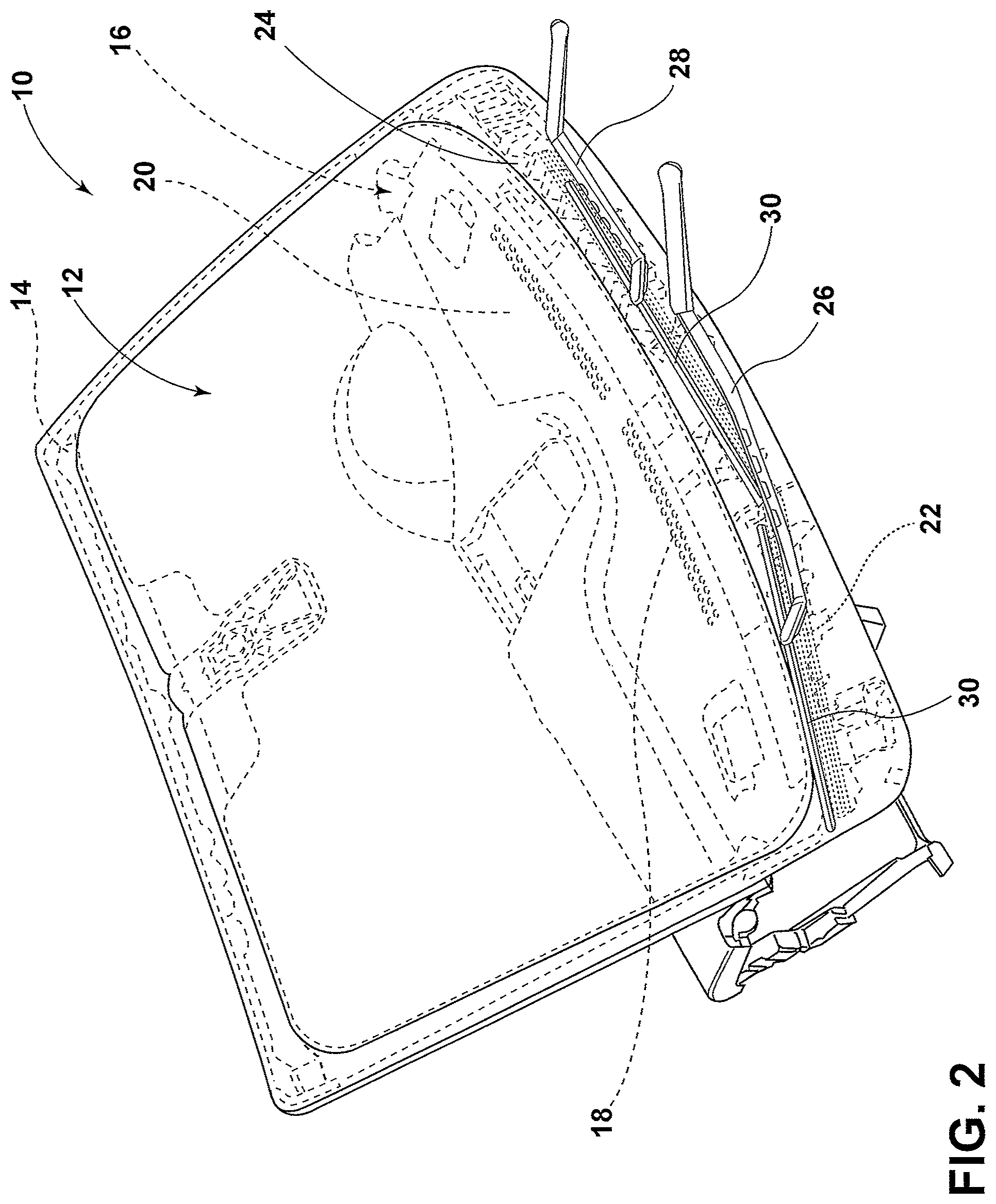
Referring to FIGS. 1 and 2, a front windshield assembly 10 of a vehicle is shown according to one embodiment. The front windshield assembly 10 includes a windshield 12, typically of glass construction, mounted to a windshield frame 14 by conventional means. As depicted in the present embodiment, the windshield 12 is disposed at an angle above a dashboard 16 having defroster ducts 18 defined in a top surface 20 of the dashboard 16. The defroster ducts 18 generally face the windshield 12 and may expel hot air in an effort to defrost the windshield 12. A heating element 22 is thermally coupled to a lower portion 24 of the windshield 12 and generally spans the length thereof. The heating element 22 may be embodied as a series of parallel linear resistive conductors provided on or in the windshield 12 and may receive power from a vehicle power supply to provide localized heating to the lower portion 24 of the windshield 12. Accordingly, the heating element 22 may function as a secondary defroster. As shown in FIG. 2, a pair of windshield wipers 26, 28 are disposed below the defroster ducts 18 such that their respective wiper blades 30 are parked against the lower portion 24 of the windshield 12. In operation, heat supplied from the heating element 22 may also serve to melt snow or ice that accumulates on the parked wiper blades 30.
Referring to FIGS. 3 and 4, the windshield 12 is shown from the vantage point of an occupant inside the vehicle. In the depicted embodiment, a frit 32 is coupled to the windshield 12 and is configured to border a periphery of thereof. The fit 32 is typically a black enamel band that provides an etched surface allowing adhesives to bond to the windshield 12 and generally serves as the contact point between the windshield 12 and the windshield frame 14. Aesthetically, the frit 32 conceals the adhesives used to install the windshield 12 and also provides shielding against ultraviolet (UV) radiation to protect the adhesive bond between the windshield 12 and the windshield frame 14. In the depicted embodiment, an indicator 34 is thermally coupled to a vehicle-inward side of the windshield 12 and is disposed to visually coincide with the frit 32. For example, the indicator 34 may visually coincide with the frit 32 proximate a lower corner portion 36 thereof on the driver side of the vehicle. By virtue of its location relative to the frit 32, the indicator 34 may be made to resemble the frit 32 when not in use, as will be described in greater detail herein. The indicator 34 may have a rectangular or square appearance when viewed head on from inside the vehicle. For purposes of illustration, the outline of the indicator 34 is exemplarily shown with dashed lining in FIG. 4. In operation, the indicator 34 is configured to sense a temperature of the windshield 12 and includes an icon 38, which is generally embodied as a front windshield defroster symbol that illuminates when the heating element 22 is activated through automatic or manual means. Like the heating element 22, the indicator 34 may also be powered by the vehicle power supply. According to one embodiment, illumination of the icon 38 indicates an activation state of the heating element 22. Additionally or alternatively, the indicator 34 may be configured such that illumination of the icon 38 indicates a relative temperature of the windshield 12.
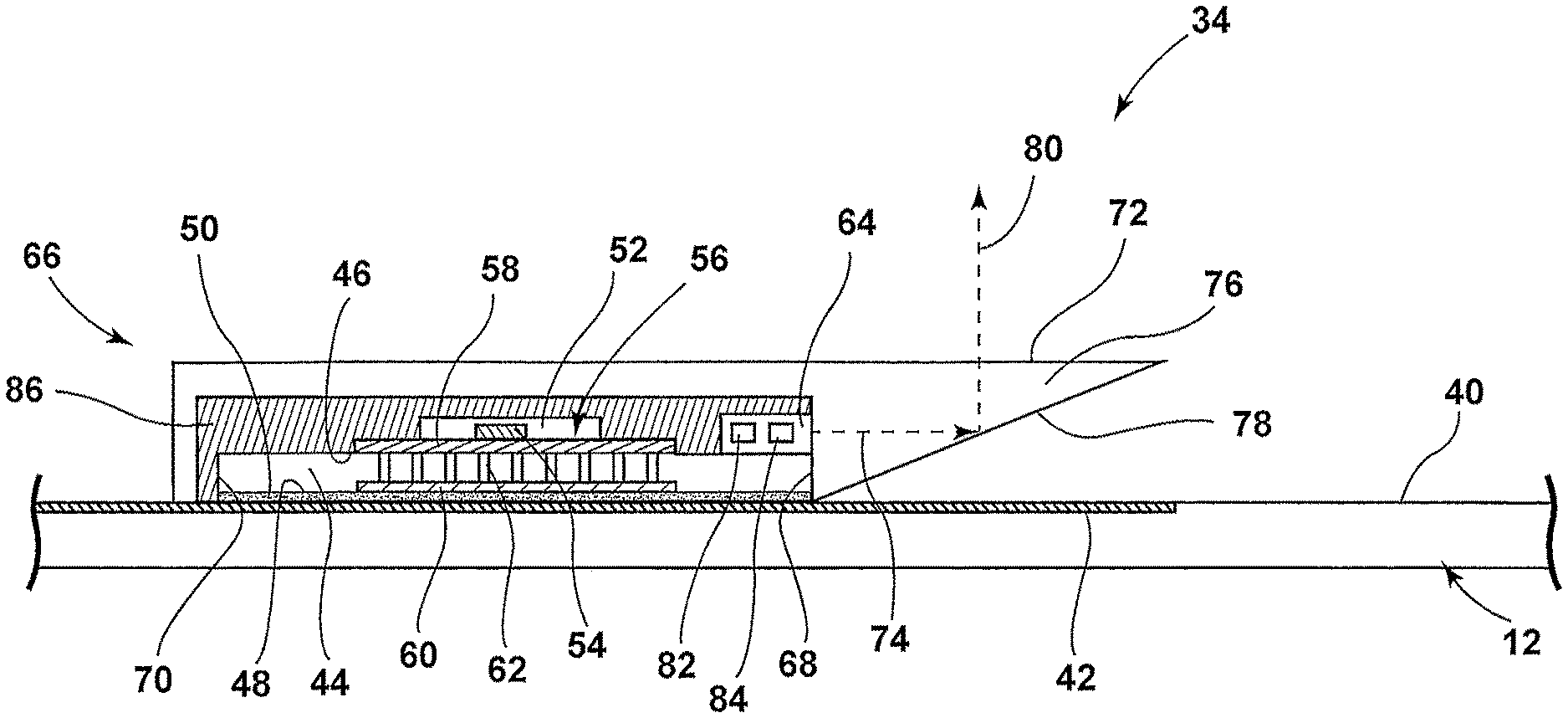
Referring to FIG. 5, a cross-sectional view of the indicator 34 is shown according to one embodiment. As shown, the indicator 34 is coupled to a vehicle-inward side 40 of the windshield 12 and visually coincides with a portion 42 of the frit 32. For purposes of illustration, portion 42 of the frit 32 is integrated in the windshield 12 but may be otherwise provided on side 40 of the windshield 12. Also, the windshield 12 is shown to be planar, but may be curved in other embodiments. In the depicted embodiment, the indicator 34 includes a printed circuit board (PCB) 44 that may be of an FR4 variety or configured as a flex circuit thereby enabling the PCB 44 to be contoured to the windshield 12. The PCB 44 includes a front side 46 and a rear side 48 that is affixed to side 40 of the windshield 12 using a thermally conductive adhesive 50. A processor 52 is provided on the front side 46 of the PCB 44 and includes a temperature sensor 54 that is thermally coupled to a thermal VIA structure 56 having a first pad 58 provided between the processor 52 and the front side 46 of the PCB 44 and a second pad 60 provided at the bottom side of the PCB 44 and thermally coupled to the adhesive 50, the first and second pads 58, 60 being connected by a plurality of barrels 62 extending through the PCB 44 from the front side 46 to the rear side 48. In this configuration, cooperation between the VIA structure 56 and the adhesive 50 enables the temperature sensor 54 of the processor 52 to sense a temperature of the windshield 12.
With continued reference to FIG. 5, the processor 52 drives a light source 64 provided at an upper portion of the front side 46 of the PCB 44. A light-transmissive cover 66 is disposed atop the PCB 44 and covers the front side 46, a top side 68, and a bottom side 70 of the PCB 44. The cover 66 includes a front side 72 on which the icon 38 is defined. For example, the cover 66 may be an overmold of optically clear silicone and the icon 38 may be molded into the silicone. Alternatively, the icon 38 may be defined using an opaque adhesive bonded to the front side 72 of the cover 66 or any other suitable means known in the art. In the depicted embodiment, the light source 64 is configured as a side emitter and emits light in a general upward direction as represented by dashed arrow 74. The cover 66 includes an optical member 76 extending past top side 68 of the PCB 44 and configured as a wedge defined by the front side 72 and a rear side 78 that extends at an upward incline relative the windshield 12. In this configuration, light emitted from the light source 64 is directed by the rear side 78 of the cover 66 toward the front side 72 on which the icon 38 is located as represented by dashed arrow 80. In alternative embodiments, the icon 38 may be directly backlit by the light source 64. In operation, the light source 64 illuminates the icon 38 to indicate at least one of an activation state of the heating element 22 and a relative temperature of the windshield 12. For example, the light source 64 may be activated in conjunction with the activation of the heating element 22 and indicate a relative temperature of the windshield 12 based on the color in which the icon 38 is illuminated.
In the depicted embodiment, the light source 64 may include a first light-emitting diode (LED) 82 configured to emit a visible light of a first color and a second LED 84 configured to emit visible light of a second color that is visually distinguishable from the first color. In one embodiment, the first LED 82 is a red-emitting LED and the second LED 84 is a green-emitting LED, each of which may be independently driven by the processor 52 via pulse-width modulation or direct current control. In order to indicate a relative temperature of the windshield 12, the first and second LEDs 82, 84 may be activated singly or in combination to illuminate the icon 38 in different colors, each indicating an associated temperature or temperature range of the windshield 12. For example, only the first LED 82 may be activated to illuminate the icon 38 in a red color whenever the temperature sensor 54 of the processor 52 registers a windshield temperature of 25 degrees Fahrenheit or less. As the windshield temperature increases due to heating from heating element 22, the first and second LEDs 82, 84 may be jointly activated to effectuate various hues of red, green, and mixtures thereof, including yellow. Once the windshield temperature reaches 50 degrees Fahrenheit or more, only the second LED 84 may remain activated. Thus, in the embodiment described above, the color green can be associated with a cold windshield temperature, the color yellow can be associated with a warm windshield temperature, and the color red can be associated with a hot windshield temperature. Accordingly, by independently controlling the first and second LEDs 82, 84 to effectuate different colored illumination of the icon 38, the indicator 34 is able to visually relate color to a relative temperature of the windshield 12. Furthermore, an occupant is able to track the relative temperature of the windshield 12 based on the color in which the icon 38 is illuminated. In operating the first and second LEDs 82, 84, the processor 52 may use lookup tables and uses temperature limits well within calibrated sensor limits of the temperature sensor 54 to ensure that the illumination of the icon 38 can progress from red to green based on the relative temperature of the windshield 12 as dictated by the heating element 22.
To conceal the indicator 34 a black solder mask 86 may be overlaid on top of the PCB 44, the processor 52, and the light source 64, thereby imparting a like appearance to the indicator 34 as the frit 32. In alternative embodiments, a pad printing process may be employed such that the cover 66 is opaque and blackened out except for portions thereof defining the icon 38. In either embodiment, when the indicator 34 is viewed head on from inside the vehicle, it will resemble the frit 32 and only the icon 38 will be observable when illuminated.
Referring to FIG. 6, another embodiment of the indicator 34 is shown and is similar in construction to that shown in FIG. 5. In the depicted embodiment, the icon 38 is defined via a pad printing process and portions of the cover 66 defining the icon 38 include one or more photoluminescent materials embedded therein or otherwise coupled thereto. For example, a first photoluminescent material 88 may be provided and is configured to luminesce in a first visible color in response to excitation light from one of the first and second LEDs 82, 84. Additionally, a second photoluminescent material 90 is provided and is configured to luminesce in a second visible color, visually distinguishable from the first visible color, in response to excitation light from the other of the first and second LEDs 82, 84. In one embodiment, the first photoluminescent material 88 is red-emitting and the second photoluminescent material 90 is green-emitting while the first LED 82 emits UV light and the second LED 84 emits blue light. In such a configuration, the processor 52 may operate the first and second LEDs 82, 84 in the same manner as described above with reference to FIG. 5 to effectuate luminescence of the icon 38 in a red color, a green color, or a mixture thereof. With respect to the embodiments described with reference to FIGS. 5 and 6, the light source 64 may include a single LED in alternative embodiments, wherein the relative temperature of the windshield 12 is instead indicated by an intensity level in which the icon 38 is illuminated.
It is to be understood that variations and modifications can be made on the aforementioned structure without departing from the concepts of the present invention, and further it is to be understood that such concepts are intended to be covered by the following claims unless these claims by their language expressly state otherwise.
* * * * *
D00000
D00001
D00002
D00003
D00004
D00005
D00006
XML
uspto.report is an independent third-party trademark research tool that is not affiliated, endorsed, or sponsored by the United States Patent and Trademark Office (USPTO) or any other governmental organization. The information provided by uspto.report is based on publicly available data at the time of writing and is intended for informational purposes only.
While we strive to provide accurate and up-to-date information, we do not guarantee the accuracy, completeness, reliability, or suitability of the information displayed on this site. The use of this site is at your own risk. Any reliance you place on such information is therefore strictly at your own risk.
All official trademark data, including owner information, should be verified by visiting the official USPTO website at www.uspto.gov. This site is not intended to replace professional legal advice and should not be used as a substitute for consulting with a legal professional who is knowledgeable about trademark law.