Devices and methods for the treatment of heart failure
Celermajer
U.S. patent number 10,624,621 [Application Number 12/447,617] was granted by the patent office on 2020-04-21 for devices and methods for the treatment of heart failure. This patent grant is currently assigned to Corvia Medical, Inc.. The grantee listed for this patent is David Stephen Celermajer. Invention is credited to David Stephen Celermajer.


View All Diagrams
| United States Patent | 10,624,621 |
| Celermajer | April 21, 2020 |
Devices and methods for the treatment of heart failure
Abstract
A device (10) for treating heart failure in a patient. The device (10) comprising a body (12), at least one passage (18) through the body (12), at least one one way valve (20) in the passage (18) and a mounting means (14) adapted for mounting the body (12) in an opening provided in the patient's atrial septum. In use, the device (10) is oriented such that, when the patient's left atrial pressure exceeds the patient's right atrial pressure by a predetermined amount, the one way valve(s) (20) opens to allow blood flow through the passage(s) from the left atrium to the right atrium to thereby reduce the left atrial pressure.
| Inventors: | Celermajer; David Stephen (Vaucluse, AU) | ||||||||||
|---|---|---|---|---|---|---|---|---|---|---|---|
| Applicant: |
|
||||||||||
| Assignee: | Corvia Medical, Inc.
(Tewksbury, MA) |
||||||||||
| Family ID: | 39364100 | ||||||||||
| Appl. No.: | 12/447,617 | ||||||||||
| Filed: | November 7, 2007 | ||||||||||
| PCT Filed: | November 07, 2007 | ||||||||||
| PCT No.: | PCT/AU2007/001704 | ||||||||||
| 371(c)(1),(2),(4) Date: | April 28, 2009 | ||||||||||
| PCT Pub. No.: | WO2008/055301 | ||||||||||
| PCT Pub. Date: | May 15, 2008 |
Prior Publication Data
| Document Identifier | Publication Date | |
|---|---|---|
| US 20100057192 A1 | Mar 4, 2010 | |
Foreign Application Priority Data
| Nov 7, 2006 [AU] | 2006906202 | |||
| Current U.S. Class: | 1/1 |
| Current CPC Class: | A61F 2/06 (20130101); A61F 2/2412 (20130101); A61B 17/02 (20130101); A61F 2/24 (20130101); A61F 2/2475 (20130101); A61M 27/002 (20130101); A61F 2/2442 (20130101); A61B 17/0057 (20130101); A61B 2017/00575 (20130101); A61B 2017/00252 (20130101); A61B 2017/00606 (20130101); A61B 2017/00867 (20130101); A61B 2017/0237 (20130101); A61B 2017/00592 (20130101) |
| Current International Class: | A61F 2/82 (20130101); A61B 17/02 (20060101); A61B 17/00 (20060101); A61M 27/00 (20060101); A61F 2/24 (20060101); A61F 2/06 (20130101) |
| Field of Search: | ;623/1.24,1.26 ;604/8 |
References Cited [Referenced By]
U.S. Patent Documents
| 3837345 | September 1974 | Matar |
| 3874388 | April 1975 | King et al. |
| 4018228 | April 1977 | Goosen |
| 4373216 | February 1983 | Klawitter |
| 4491986 | January 1985 | Gabbay |
| 4655217 | April 1987 | Reed |
| 4705507 | November 1987 | Boyles |
| 5100423 | March 1992 | Fearnot |
| 5108420 | April 1992 | Marks |
| 5171233 | December 1992 | Amplatz et al. |
| 5284488 | February 1994 | Sideris |
| 5332402 | July 1994 | Teitelbaum |
| 5334217 | August 1994 | Das |
| 5387219 | February 1995 | Rapper |
| 5413599 | May 1995 | Imachi et al. |
| 5429144 | July 1995 | Wilk |
| 5433727 | July 1995 | Sideris |
| 5464449 | November 1995 | Ryan et al. |
| 5478353 | December 1995 | Yoon |
| 5488958 | February 1996 | Topel et al. |
| 5556386 | September 1996 | Todd |
| 5556408 | September 1996 | Farhat |
| 5693090 | December 1997 | Unsworth et al. |
| 5702412 | December 1997 | Popov et al. |
| 5725552 | March 1998 | Kotula et al. |
| 5741297 | April 1998 | Simon |
| 5824071 | October 1998 | Nelson et al. |
| 5846261 | December 1998 | Kotula et al. |
| 5876436 | March 1999 | Vanney et al. |
| 5893369 | April 1999 | Lemole |
| 5944738 | August 1999 | Amplatz et al. |
| 5964754 | October 1999 | Osypka |
| 6050936 | April 2000 | Schweich, Jr. et al. |
| 6059827 | May 2000 | Fenton |
| 6068635 | May 2000 | Gianotti |
| 6120534 | September 2000 | Ruiz |
| 6123682 | September 2000 | Knudson et al. |
| 6123715 | September 2000 | Amplatz |
| 6152937 | November 2000 | Peterson et al. |
| 6156055 | December 2000 | Ravenscroft |
| 6168622 | January 2001 | Mazzocchi |
| 6190353 | February 2001 | Makower et al. |
| 6193734 | February 2001 | Bolduc et al. |
| 6210338 | April 2001 | Afremov et al. |
| 6214029 | April 2001 | Thill et al. |
| 6241678 | June 2001 | Afremov et al. |
| 6258119 | July 2001 | Hussein et al. |
| 6283983 | September 2001 | Makower et al. |
| 6286512 | September 2001 | Loeb et al. |
| 6334864 | January 2002 | Amplatz et al. |
| 6350277 | February 2002 | Kocur |
| 6355052 | March 2002 | Neuss et al. |
| 6355056 | March 2002 | Pinheiro |
| 6357735 | March 2002 | Haverinen |
| 6383195 | May 2002 | Richard |
| 6391036 | May 2002 | Berg et al. |
| 6395017 | May 2002 | Dwyer et al. |
| 6402777 | June 2002 | Globerman et al. |
| 6409716 | June 2002 | Sahatjian et al. |
| 6440152 | August 2002 | Gainor et al. |
| 6454795 | September 2002 | Chuter |
| 6458153 | October 2002 | Bailey et al. |
| 6468301 | October 2002 | Amplatz et al. |
| 6468303 | October 2002 | Amplatz et al. |
| 6527746 | March 2003 | Oslund et al. |
| 6527768 | March 2003 | Berube |
| 6572652 | June 2003 | Shaknovich |
| 6579311 | June 2003 | Makower |
| 6599308 | July 2003 | Amplatz |
| 6626936 | September 2003 | Stinson |
| 6638257 | October 2003 | Amplatz |
| 6645143 | November 2003 | Vantassel et al. |
| 6666885 | December 2003 | Moe |
| 6699256 | March 2004 | Logan et al. |
| 6712836 | March 2004 | Berg et al. |
| 6719768 | April 2004 | Cole et al. |
| 6719934 | April 2004 | Stinson |
| 6837901 | January 2005 | Rabkin et al. |
| 6866679 | March 2005 | Kusleika |
| 6911037 | June 2005 | Gainor et al. |
| 6913614 | July 2005 | Marino et al. |
| 6932837 | August 2005 | Amplatz et al. |
| 6936058 | August 2005 | Forde et al. |
| 6979343 | December 2005 | Russo et al. |
| 7033372 | April 2006 | Cahalan |
| 7037329 | May 2006 | Martin |
| 7044134 | May 2006 | Khairkhahan et al. |
| 7097653 | August 2006 | Freudenthal et al. |
| 7105024 | September 2006 | Richelsoph |
| 7144410 | December 2006 | Marino et al. |
| 7226466 | June 2007 | Opolski |
| 7309341 | December 2007 | Ortiz et al. |
| 7317951 | January 2008 | Schneider et al. |
| 7338514 | March 2008 | Wahr et al. |
| 7350995 | April 2008 | Rhodes |
| 7419498 | September 2008 | Opolski et al. |
| 7445630 | November 2008 | Lashinski et al. |
| 7473266 | January 2009 | Glaser |
| 7485141 | February 2009 | Majercak et al. |
| 7530995 | May 2009 | Quijano et al. |
| 7611534 | November 2009 | Kapadia et al. |
| 7625392 | December 2009 | Coleman et al. |
| 7658747 | February 2010 | Forde et al. |
| 7678123 | March 2010 | Chanduszko |
| 7691144 | April 2010 | Chang et al. |
| 7699297 | April 2010 | Cicenas et al. |
| 7704268 | April 2010 | Chanduszko |
| 7722629 | May 2010 | Chambers |
| 7758589 | July 2010 | Ortiz et al. |
| 7842026 | November 2010 | Cahill et al. |
| 7860579 | December 2010 | Goetzinger et al. |
| 7871419 | January 2011 | Devellian et al. |
| 7905901 | March 2011 | Corcoran et al. |
| 7967769 | June 2011 | Faul et al. |
| 7976564 | July 2011 | Blaeser et al. |
| 8010186 | August 2011 | Ryu |
| 8021359 | September 2011 | Auth et al. |
| 8034061 | October 2011 | Amplatz et al. |
| 8043360 | October 2011 | McNamara et al. |
| 8048147 | November 2011 | Adams |
| 8052750 | November 2011 | Tuval et al. |
| 8157860 | April 2012 | McNamara et al. |
| 8172896 | May 2012 | McNamara et al. |
| 8252042 | August 2012 | McNamara et al. |
| 8303623 | November 2012 | Melzer et al. |
| 8313505 | November 2012 | Amplatz et al. |
| 8361138 | January 2013 | Adams |
| 8398670 | March 2013 | Amplatz et al. |
| 8460372 | June 2013 | McNamara et al. |
| 8740962 | June 2014 | Finch et al. |
| 8745845 | June 2014 | Finch et al. |
| 8752258 | June 2014 | Finch et al. |
| 8777974 | July 2014 | Amplatz et al. |
| 8778008 | July 2014 | Amplatz et al. |
| 8864822 | October 2014 | Spence et al. |
| 8882697 | November 2014 | Celermajer et al. |
| 8979923 | March 2015 | Spence et al. |
| 9681948 | June 2017 | Levi et al. |
| 9724499 | August 2017 | Rottenberg et al. |
| 2001/0027287 | October 2001 | Shmulewitz et al. |
| 2001/0053932 | December 2001 | Phelps |
| 2002/0033180 | March 2002 | Solem |
| 2002/0077698 | June 2002 | Peredo |
| 2002/0082525 | June 2002 | Oslund et al. |
| 2002/0082613 | June 2002 | Hathaway et al. |
| 2002/0095172 | July 2002 | Mazzocchi et al. |
| 2002/0120277 | August 2002 | Hauschild et al. |
| 2002/0143289 | October 2002 | Ellis et al. |
| 2002/0161424 | October 2002 | Rapacki et al. |
| 2002/0161432 | October 2002 | Mazzucco et al. |
| 2002/0165606 | November 2002 | Wolf et al. |
| 2002/0169377 | November 2002 | Khairkhahan et al. |
| 2002/0173742 | November 2002 | Keren et al. |
| 2002/0177894 | November 2002 | Acosta et al. |
| 2002/0183826 | December 2002 | Dorn et al. |
| 2003/0032967 | February 2003 | Park et al. |
| 2003/0093072 | May 2003 | Friedman |
| 2003/0125798 | July 2003 | Martin |
| 2004/0044351 | March 2004 | Searle |
| 2004/0078950 | April 2004 | Schreck |
| 2004/0087937 | May 2004 | Eggers et al. |
| 2004/0093075 | May 2004 | Kuehne |
| 2004/0102719 | May 2004 | Keith et al. |
| 2004/0102797 | May 2004 | Golden et al. |
| 2004/0111095 | June 2004 | Gordon et al. |
| 2004/0133236 | July 2004 | Chanduszko |
| 2004/0143261 | July 2004 | Hartley et al. |
| 2004/0143262 | July 2004 | Visram et al. |
| 2004/0143292 | July 2004 | Marino et al. |
| 2004/0162514 | August 2004 | Alferness et al. |
| 2004/0176788 | September 2004 | Opolski |
| 2004/0193261 | September 2004 | Berreklouw |
| 2004/0206363 | October 2004 | McCarthy et al. |
| 2004/0220653 | November 2004 | Borg et al. |
| 2004/0236308 | November 2004 | Herweck et al. |
| 2004/0243143 | December 2004 | Corcoran et al. |
| 2004/0267306 | December 2004 | Blaeser et al. |
| 2005/0015953 | January 2005 | Keidar |
| 2005/0049692 | March 2005 | Numamoto et al. |
| 2005/0049697 | March 2005 | Sievers |
| 2005/0065507 | March 2005 | Hartley et al. |
| 2005/0065546 | March 2005 | Corcoran et al. |
| 2005/0065548 | March 2005 | Marino et al. |
| 2005/0070934 | March 2005 | Tanaka et al. |
| 2005/0075655 | April 2005 | Bumbalough et al. |
| 2005/0075665 | April 2005 | Brenzel et al. |
| 2005/0080400 | April 2005 | Corcoran et al. |
| 2005/0080430 | April 2005 | Wright et al. |
| 2005/0096735 | May 2005 | Hojeibane et al. |
| 2005/0113868 | May 2005 | Devellian et al. |
| 2005/0131503 | June 2005 | Solem |
| 2005/0137609 | June 2005 | Guiraudon |
| 2005/0137686 | June 2005 | Salahieh et al. |
| 2005/0148925 | July 2005 | Rottenberg et al. |
| 2005/0159738 | July 2005 | Visram et al. |
| 2005/0165344 | July 2005 | Dobak, III |
| 2005/0187616 | August 2005 | Realyvasquez |
| 2005/0234537 | October 2005 | Edin |
| 2005/0240205 | October 2005 | Berg et al. |
| 2005/0251063 | November 2005 | Basude |
| 2005/0251187 | November 2005 | Beane et al. |
| 2005/0267524 | December 2005 | Chanduszko |
| 2005/0273075 | December 2005 | Krulevitch et al. |
| 2005/0273124 | December 2005 | Chanduszko |
| 2005/0288722 | December 2005 | Eigler et al. |
| 2006/0004323 | January 2006 | Chang et al. |
| 2006/0009800 | January 2006 | Christianson et al. |
| 2006/0009832 | January 2006 | Fisher |
| 2006/0041183 | February 2006 | Massen et al. |
| 2006/0085060 | April 2006 | Campbell |
| 2006/0095066 | May 2006 | Chang et al. |
| 2006/0111704 | May 2006 | Brenneman et al. |
| 2006/0122646 | June 2006 | Corcoran et al. |
| 2006/0122647 | June 2006 | Callaghan et al. |
| 2006/0135990 | June 2006 | Johnson |
| 2006/0136043 | June 2006 | Cully et al. |
| 2006/0155305 | July 2006 | Freudenthal et al. |
| 2006/0184088 | August 2006 | Van Bibber et al. |
| 2006/0210605 | September 2006 | Chang et al. |
| 2006/0217761 | September 2006 | Opolski |
| 2006/0224183 | October 2006 | Freudenthal |
| 2006/0241675 | October 2006 | Johnson et al. |
| 2006/0241745 | October 2006 | Solem |
| 2006/0247680 | November 2006 | Amplatz et al. |
| 2006/0253184 | November 2006 | Amplatz |
| 2006/0259121 | November 2006 | Osypka |
| 2006/0276882 | December 2006 | Case et al. |
| 2007/0005127 | January 2007 | Boekstegers et al. |
| 2007/0010851 | January 2007 | Chanduszko et al. |
| 2007/0021739 | January 2007 | Weber |
| 2007/0027528 | February 2007 | Agnew |
| 2007/0038295 | February 2007 | Case et al. |
| 2007/0043431 | February 2007 | Melsheimer |
| 2007/0088375 | April 2007 | Beane et al. |
| 2007/0088388 | April 2007 | Opolski et al. |
| 2007/0118207 | May 2007 | Amplatz et al. |
| 2007/0123934 | May 2007 | Whisenant et al. |
| 2007/0129755 | June 2007 | Abbott et al. |
| 2007/0168018 | July 2007 | Amplatz et al. |
| 2007/0185513 | August 2007 | Woolfson et al. |
| 2007/0197952 | August 2007 | Stiger |
| 2007/0198060 | August 2007 | Devellian et al. |
| 2007/0209957 | September 2007 | Glenn et al. |
| 2007/0225759 | September 2007 | Thommen et al. |
| 2007/0265658 | November 2007 | Nelson et al. |
| 2007/0270741 | November 2007 | Hassett et al. |
| 2007/0282157 | December 2007 | Rottenberg et al. |
| 2008/0015619 | January 2008 | Figulla et al. |
| 2008/0033425 | February 2008 | Davis et al. |
| 2008/0033478 | February 2008 | Meng |
| 2008/0033543 | February 2008 | Gurskis et al. |
| 2008/0039804 | February 2008 | Edmiston et al. |
| 2008/0039881 | February 2008 | Greenberg |
| 2008/0039922 | February 2008 | Miles et al. |
| 2008/0071135 | February 2008 | Shaknovich |
| 2008/0058940 | March 2008 | Wu et al. |
| 2008/0086168 | April 2008 | Cahill |
| 2008/0103508 | May 2008 | Karakurum |
| 2008/0109069 | May 2008 | Coleman et al. |
| 2008/0119891 | May 2008 | Miles et al. |
| 2008/0125861 | May 2008 | Webler et al. |
| 2008/0154250 | June 2008 | Makower et al. |
| 2008/0154302 | June 2008 | Opolski et al. |
| 2008/0154351 | June 2008 | Leewood et al. |
| 2008/0154355 | June 2008 | Benichou et al. |
| 2008/0161901 | July 2008 | Heuser et al. |
| 2008/0172123 | July 2008 | Yadin |
| 2008/0177381 | July 2008 | Navia et al. |
| 2008/0183279 | July 2008 | Bailey et al. |
| 2008/0188880 | August 2008 | Fischer et al. |
| 2008/0188888 | August 2008 | Adams et al. |
| 2008/0215008 | September 2008 | Nance et al. |
| 2008/0221582 | September 2008 | Gia et al. |
| 2008/0228264 | September 2008 | Li et al. |
| 2008/0249397 | October 2008 | Kapadia |
| 2008/0249562 | October 2008 | Cahill |
| 2008/0249612 | October 2008 | Osborne et al. |
| 2008/0262592 | October 2008 | Jordan et al. |
| 2008/0269662 | October 2008 | Vassiliades et al. |
| 2008/0312679 | December 2008 | Hardert et al. |
| 2009/0018570 | January 2009 | Righini et al. |
| 2009/0030495 | January 2009 | Koch |
| 2009/0054805 | February 2009 | Boyle |
| 2009/0054982 | February 2009 | Cimino |
| 2009/0054984 | February 2009 | Shortkroff et al. |
| 2009/0062841 | March 2009 | Amplatz et al. |
| 2009/0076541 | March 2009 | Chin et al. |
| 2009/0082803 | March 2009 | Adams et al. |
| 2009/0099647 | April 2009 | Glimsdale et al. |
| 2009/0112050 | April 2009 | Farnan et al. |
| 2009/0112244 | April 2009 | Freudenthal |
| 2009/0112251 | April 2009 | Qian et al. |
| 2009/0177269 | July 2009 | Kalmann et al. |
| 2009/0234443 | September 2009 | Ottma et al. |
| 2010/0030259 | February 2010 | Pavcnik et al. |
| 2010/0114140 | May 2010 | Chanduszko |
| 2010/0131053 | May 2010 | Agnew |
| 2010/0268316 | October 2010 | Brenneman et al. |
| 2010/0298755 | November 2010 | McNamara et al. |
| 2011/0004296 | January 2011 | Lutter et al. |
| 2011/0040374 | February 2011 | Goetz et al. |
| 2011/0071623 | March 2011 | Finch et al. |
| 2011/0071624 | March 2011 | Finch et al. |
| 2011/0106149 | May 2011 | Ryan et al. |
| 2011/0130784 | June 2011 | Kusleika |
| 2011/0190874 | August 2011 | Celermajer et al. |
| 2011/0213364 | September 2011 | Davis et al. |
| 2011/0218479 | September 2011 | Rottenberg et al. |
| 2011/0257723 | October 2011 | McNamara |
| 2011/0295183 | December 2011 | Finch et al. |
| 2012/0130301 | May 2012 | McNamara et al. |
| 2012/0265296 | October 2012 | McNamara et al. |
| 2012/0289882 | November 2012 | McNamara et al. |
| 2012/0290062 | November 2012 | McNamara et al. |
| 2013/0178783 | July 2013 | McNamara et al. |
| 2013/0178784 | July 2013 | McNamara et al. |
| 2013/0184633 | July 2013 | McNamara et al. |
| 2013/0184634 | July 2013 | McNamara et al. |
| 2013/0204175 | August 2013 | Sugimoto |
| 2013/0231737 | September 2013 | McNamara et al. |
| 2013/0267885 | October 2013 | Celermajer et al. |
| 2014/0012368 | January 2014 | Sugimoto et al. |
| 2014/0194971 | July 2014 | McNamara |
| 2014/0257167 | September 2014 | Celermajer et al. |
| 2014/0277054 | September 2014 | McNamara et al. |
| 2015/0039084 | February 2015 | Levi et al. |
| 2015/0119796 | April 2015 | Finch |
| 2016/0051800 | February 2016 | Vassiliades et al. |
| 2016/0120550 | May 2016 | McNamara et al. |
| 2017/0128705 | May 2017 | Forcucci et al. |
| 2018/0256865 | September 2018 | Finch et al. |
| 2019/0021861 | January 2019 | Finch |
| 2019/0269392 | September 2019 | Celermajer et al. |
| 1218379 | Jun 1999 | CN | |||
| 1556719 | Dec 2004 | CN | |||
| 1582136 | Feb 2005 | CN | |||
| 1780589 | May 2006 | CN | |||
| 101035481 | Sep 2007 | CN | |||
| 101035488 | Sep 2007 | CN | |||
| 101292889 | Oct 2008 | CN | |||
| 101426431 | May 2009 | CN | |||
| 1264582 | Feb 2002 | EP | |||
| 1480565 | Sep 2003 | EP | |||
| 1470785 | Oct 2004 | EP | |||
| 1849440 | Oct 2007 | EP | |||
| 2827153 | Jan 2003 | FR | |||
| 58-27935 | Jun 1983 | JP | |||
| H02-277459 | Nov 1990 | JP | |||
| 2003530143 | Oct 2003 | JP | |||
| WO95/27448 | Oct 1995 | WO | |||
| WO98/08456 | Mar 1998 | WO | |||
| WO98/42403 | Oct 1998 | WO | |||
| WO-00/15149 | Mar 2000 | WO | |||
| WO01/15618 | Mar 2001 | WO | |||
| WO-01/49213 | Jul 2001 | WO | |||
| WO02/094363 | Nov 2002 | WO | |||
| WO-04/019811 | Mar 2004 | WO | |||
| WO2005/048881 | Jun 2005 | WO | |||
| WO2005/048883 | Jun 2005 | WO | |||
| WO2006/127765 | Nov 2006 | WO | |||
| WO2007/054116 | May 2007 | WO | |||
| WO2007/083288 | Jul 2007 | WO | |||
| 2008/058940 | May 2008 | WO | |||
| WO-2008058940 | May 2008 | WO | |||
Other References
|
International Search Report, PCT/AU2007/001704, dated Jan. 16, 2008, 4 pages. cited by applicant . Nanotechnology in Prosthetic Heart Valves, Steven R. Bailey, MD, approx. date 2005, presentation, 31 pages. cited by applicant . A Philosophical Approach to Mitral Valve Repair, Vincent A. Gaudiani, MD and Audrey L. Fisher, MPH, Apr. 24, 2009, presentation, 28 pages. cited by applicant . Direct Flow Medical--My Valve is Better, Steven F. Bolling, MD, Apr. 23, 2009, presentation, 21 pages. cited by applicant . No! Valve Replacement: Patient Prosthetic Mismatch Rarely Occurs, Joseph S. Coselli, MD, Apr. 25, 2009, presentation, 75 pages. cited by applicant . Transcatheter Aortic Valve Therapy: Summary Thoughts, Martin B. Leon, MD, Jun. 24, 2009, presentation, 19 pages. cited by applicant . The Good, the Bad and the Ugly of Transcatheter AVR, Jeffrey W. Moses, MD, Jul. 10, 2009, presentation, 28 pages. cited by applicant . Valve Implantation, Ziyad M. Hijazi, MD, May 10, 2007, presentation, 36 pages. cited by applicant . Transcatheter Devices for Mitral Valve Repair, Surveying the Landscape, Gregg W. Stone, MD, Jul. 10, 2009, presentation, 48 pages. cited by applicant . Comparative Study of in vitro Flow Characteristics between a Human Aortic Valve and a Designed Aortic Valve and Six Corresponding Types of Prosthetic Heart Valves, B. Stormer et al., Eur. Surg. Res. 8: 117-131 (1976), 15 pages. cited by applicant . The Use of an Artificial Foraminal Valve Prosthesis in the Closure of Interatrial and Interventricular Septal Defects, Ramon Larios et al., Dis. Chest 1959: 36; 631-41, 12 pages. cited by applicant . Insertion of a Fenestrated Amplatzer Atrial Sestosotomy Device for Severe Pulmonary Hypertension, A.J. O'Loughlin et al., Heart Lung Circ. 2006, 15(4):275-77, 3 pages. cited by applicant . Long-Term Follow up of a Fenestrated Amplatzer Atrial Septal Occluder in Pulmonary Arterial Hypertension, T.F. Althoff, et al., Chest 2008, 133:183-85, 5 pages. cited by applicant . International Search Report, PCTUS2010/026574, dated Nov. 19, 2010, 4 pages. cited by applicant . Supplementary Partial European Search Report, dated Jul. 17, 2012 for European Application No. EP07815507 filed Nov. 7, 2007, 6 pages. cited by applicant . Ad et al.; A one way valved atrial septal patch: A new surgical technique and its clinical application; The Journal of Thoracic and Cardiovascular Surgery; 111; pp. 841-848; Apr. 1996. cited by applicant . Atz et al.; Preoperative management of pulmonary venous hypertension in hypoplastic left heart syndrome with restrictive atrial septal defect; the American Journal of Cardiology; 83; pp. 1224-1228; Apr. 15, 1999. cited by applicant . Cheatham, John P.; Intervention in the critically ill neonate and infant with hypoplastic left heart syndrome and intact atrial septum; Journal of Interventional Cardiology; 14(3); pp. 357-366; Jun. 2001. cited by applicant . Design News; Low power piezo motion; retrieved from the internet (http://www.designnews.com/document.asp?doc_id=229053&dfpPParams=ht__13,a- id_229053&dfpLayout=article); 3 pgs.; May 14, 2010. cited by applicant . Park et al.; Blade atrial septostomy: Collaborative study; Circulation; 66(2); pp. 258-266; Aug. 1982. cited by applicant . Pedra et al.; Stent implantation to create interatrial communications in patients with complex congenital heart disease; Catheterization and Cardiovascular Interventions; 47; pp. 310-313; Jan. 27, 1999. cited by applicant . Perry et al.; Creation and maintenance of an adequate interatrial communication in left atrioventricular valve atresia or stenosis; The American Journal of Cardiology; 58; pp. 622-626; Sep. 15, 1986. cited by applicant . Philips et al.; Ventriculofemoroatrial shunt: A viable alternative for the treatment of hydrocephalus; J. Neurosurg.; 86; pp. 1063-1066; Jun. 1997. cited by applicant . Physik Instrumente; Piezo for Motion Control in Medical Design and Drug Research (product information); Physik Instrumente (PI) GmbH & Co. KG; 22 pgs.; .COPYRGT. Nov. 21, 2010. cited by applicant . Roven et al.; Effect of compromising right ventricular function in left ventricular failure by means of interatrial and other shunts; Am J Cardiol.; 24(2); pp. 209-219; Aug. 1969. cited by applicant . Sambhi et al.; Pathologic Physiology of Lutembacher Syndrome; Am J Cardiol.; 2(6); pp. 681-686; Dec. 1958. cited by applicant . Sommer et al.; Transcatheter creation of atrial septal defect and fontan fenestration with "butterfly" stent technique; Journal of the American college of Cardiology; 33(2); Suppl. A; 3 pgs.; Feb. 1999. cited by applicant . Watterson et al.; Very small pulmonary arteries: Central end-to-side shunt; Ann. Thorac. Surg.; 52(5); pp. 1132-1137; Nov. 1991. cited by applicant . Celermajer et al.; U.S. Appl. No. 14/498,903 entitled "Apparatus and methods to create and maintain an intra-atrial pressure relief opening," filed Sep. 26, 2014. cited by applicant . Mcnamara et al.; U.S. Appl. No. 14/612,022 entitled "Methods and devices for intra-atrial shunts having adjustable sizes," filed Feb. 2, 2015. cited by applicant . Sugimoto et al.; U.S. Appl. No. 14/986,409 entitled "Devices and methods for retrievable intra-atrial implants," filed Dec. 31, 2015. cited by applicant . Forcucci et al.; U.S. Appl. No. 14/807,544 entitled "Devices and methods for treating heart failure," filed Jul. 23, 2015. cited by applicant . Finch; U.S. Appl. No. 14/645,416 entitled "Devices and methods for treating heart failure," filed Mar. 11, 2015. cited by applicant . Mcnamara et al.; U.S. Appl. No. 14/878,710 entitled "Methods, systems, and devices for resizable intra-atrial shunts," filed Oct. 8, 2015. cited by applicant. |
Primary Examiner: Schall; Matthew W
Attorney, Agent or Firm: Shay Glenn LLP
Claims
The invention claimed is:
1. A device for treating a heart condition in a patient, the device comprising: a body comprising an inner lumen defining at least one passageway with a first end and a second end, wherein the body has a collapsed configuration with a reduced diameter for passing through a catheter, and an expanded configuration with a larger diameter; a first flange and a second flange positioned on either end of the body, wherein both the first and the second flange have a collapsed tubular configuration with a first portion joining the body at a first end of the first portion and a second portion joining the first portion at a second end of the first portion, and an expanded flange configuration with the first portion of both flanges forming a first exterior face and the second portion of both flanges forming a second exterior face, wherein, in the expanded configuration, the first and second flanges are adapted for mounting the body in an opening in the patient's atrial septum each with the first exterior face contacting the atrial septum, and the second exterior face facing away from the atrial septum, and wherein, in the collapsed configuration, both exterior faces of the first and second flanges extend away from one another causing the first and second flanges to lengthen and resume the tubular configuration; and at least one valve disposed inside the passageway, the valve positioned closer to a central portion of the passageway than the first or second ends of the passageway, along a longitudinal axis of the passageway, wherein the at least one valve is adapted to open and allow blood flow through the passageway from the left atrium to the right atrium to thereby reduce the left atrial pressure when the patient's left atrial pressure exceeds the patient's right atrial pressure by a predetermined amount and prevent flow from the right atrium to the left atrium when the right atrial pressure exceeds the left atrial pressure.
2. The device recited in claim 1, wherein the valve is one of a duckbill valve, a leaflet valve, a flap valve, a disc in cage type valve and a ball in cage type valve.
3. The device recited in claim 2, wherein the valve is biased in a closed position.
4. The device as recited in claim 2, wherein the valve is constructed of a resilient material and is biased to the closed position by the force applied by the resilient material.
5. The device as recited in claim 1, wherein the valve opens when the predetermined amount of pressure differential is approximately 2 mm Hg.
6. The device as recited in claim 1, wherein the valve opens when the predetermined amount of pressure differential is approximately 5 to 25 mm Hg.
7. The device as recited in claim 1, wherein the valve opens when the predetermined amount of pressure differential is approximately 5 to 15 mm Hg.
8. The device as recited in claim 1 wherein body defines a single passageway into which a valve is disposed.
9. The device as recited in claim 8, wherein the body includes a central axis and the single passageway is located along the central axis of the body.
10. The device as recited in claim 8, wherein the body includes a central axis and the single passageway is located off the central axis of the body.
11. The device as recited in claim 1, wherein the body defines a plurality of passageways through the body and further comprising a one way valve in each passageway.
12. The device as recited in claim 11, wherein the device includes a central axis and the plurality of passageways are located off the central axis of the body.
13. The device as recited in claim 1, wherein the device is flexible and is deliverable to an implant site via a catheter.
14. The device as recited in claim 13, wherein the device is formed from a material which can be deformed but later return to its original shape.
15. The device as recited in claim 14, wherein the device is formed at least in part from Nitinol.
16. The device as recited in claim 1, wherein the device includes a first configuration that has a reduced cross sectional profile and a second configuration that is adapted for implantation in the body, the first configuration being adapted to deliver the device via a catheter.
17. The device as recited in claim 1, wherein the device is collapsible to a size able to pass through an opening made in the patient's atrial septum and adapted to return to a shape where at least some of the device would be unable to pass through the opening in the patient's atrial septum.
18. The device as recited in claim 17, wherein the device is formed at least in part by a Nitinol mesh.
19. The device as recited in any one of the claim 1, wherein at least one of the first and second flange has a radial dimension larger than the opening in the patient's septum.
20. The device as recited in claim 1, wherein the first and second flanges have a dimension larger than the opening in the patient's septum.
21. The device as recited in claim 1, wherein the first and second flanges are adapted for attaching to the patient's septum by one of gluing, suturing, stapling and pinning.
22. The device as recited in claim 1, wherein the flanges are spaced apart by about the thickness of the patient's atrial septum and are adapted to position the patient's atrial septum between the flanges.
23. The device as recited in claim 1, wherein the flanges are spaced apart by about the thickness of the patient's atrial septum and are adapted to grip the patient's atrial septum between the flanges.
24. The device of claim 1, wherein the valve is disposed substantially in the center of the passageway.
25. The device of claim 1, wherein the valve is disposed away from both ends of the passageway.
Description
FIELD OF THE INVENTION
The present invention relates generally to devices and methods for the treatment of heart failure and, more particularly, to devices and methods for the relief of high pressure in the cardiovascular system to alleviate symptoms of cardiovascular disease.
BACKGROUND OF THE INVENTION
Heart failure is a common and potentially lethal condition affecting humans, with sub-optimal clinical outcomes often resulting in symptoms, morbidity and/or mortality, despite maximal medical treatment. In particular, "diastolic heart failure" refers to the clinical syndrome of heart failure occurring in the context of preserved left ventricular systolic function (ejection fraction) and in the absence of major valvular disease. This condition is characterised by a stiff left ventricle with decreased compliance and impaired relaxation, which leads to increased end-diastolic pressure. Approximately one third of patients with heart failure have diastolic heart failure and there are very few, if any, proven effective treatments.
Symptoms of diastolic heart failure are due, at least in a large part, to an elevation in pressure in the left atrium. In addition to diastolic heart failure, a number of other medical conditions, including systolic dysfunction of the left ventricle and valve disease, can lead to elevated pressures in the left atrium. Increased left atrial pressure often causes acute or chronic breathlessness amongst other problems. In addition, a variety of heart conditions can lead to "right heart failure", which can result in enlargement of the liver (hepatomegaly), fluid accumulation in the abdomen (ascites) and/or swelling of the lower limbs.
In the past, strategies have been described for the relief of high pressure in the right atrium, such as the creation of hole(s) in the native or surgically created septum between the left and right atria. These have been designed for the rare conditions of pulmonary hypertension or cavopulmonary connections for certain complex congenital heart diseases. O'Loughlin et al recently described a fenestrated atrial septal defect closure device for the palliation of advanced pulmonary hypertension. However, this device allows bidirectional flow, and the passage of thrombi, and was shown to be closed over within 6 months of insertion. Thus a need still exists for devices to relieve high pressure in the left atrium and which will prevent or minimize the chance of the passage of thrombi.
Accordingly, there exists a need for devices and methods to treat heart failure particularly diastolic and/or systolic failure of the left ventricle and its consequences.
SUMMARY OF THE INVENTION
According to a first aspect of the invention, there is provided a device for treating heart failure in a patient, the device comprising: a body; at least one passage through the body; at least one one way valve in the passage; and a mounting means adapted for mounting the body in an opening provided in the patient's atrial septum, wherein, in use, the device is oriented such that, when the patient's left atrial pressure exceeds the patient's right atrial pressure by a predetermined amount, the one way valve(s) opens to allow blood flow through the passage(s) from the left atrium to the right atrium to thereby reduce the left atrial pressure.
According to a second aspect of the invention, there is provided a device for treating heart failure or pulmonary venous hypertension in a patient, the device comprising: a body; at least one passage through the body; at least one one way valve in the passage; and a mounting means adapted for mounting the body in the patient's venous system, wherein, in use, the device is oriented such that the one way valve(s) prevents blood flow through the passage(s) in a direction opposite to that of the natural flow direction.
The device is preferably adapted to be fitted into a blood vessel in the patient's venous system, such as the inferior vena cava, superior vena cava, the hepatic vein, an iliac vein, or one or more pulmonary veins.
According to a third aspect of the invention, there is provided a device for treating lower limb venous hypertension in a patient, the device comprising: a body; at least one passage through the body; at least one one way valve in the passage; and a mounting means adapted for mounting the body in the patient's lower limb venous system, wherein, in use, the device is oriented such that the one way valve(s) prevents blood flow through the passage(s) in a direction opposite to that of the natural flow direction.
The above device is also suitable for treating varicose veins.
The body is preferably in the form of a stent, most preferably an expandable stent.
The valve is preferably a duckbill valve, a leaflet valve, a flap valve, a disc in cage type valve or a ball in cage type valve. The valve is preferably biased to a closed position, most preferably by the inherent resilience of the valve material. The valve preferably opens when the predetermined amount of pressure differential is at least approximately 2 mm Hg, preferably approximately 5 to 25 mm Hg, even more preferably 5 to 15 mm Hg.
In one form, the device has a single passage through the body, most preferably centrally located in relation to the body. In another form, the device has a single passage through the body, most preferably eccentrically located in relation to the body. In yet another form, the device has a plurality of passages through the body, each with a one way valve therein, most preferably each eccentrically located in relation to centre of the body.
According to a fourth aspect of the invention, there is provided a device for treating heart failure in a patient, the device comprising: a body; at least one passage through the body; a mesh or grill arrangement within the passage and having apertures therein of a size permitting flow of blood, whilst substantially excluding thrombi, therethrough; a mounting means adapted for mounting the body in an opening provided in the patient's atrial septum, wherein, in use, the device allows blood flow through the passage(s) from the left atrium to the right atrium when the patient's left atrial pressure exceeds the patient's right atrial pressure to thereby reduce the patient's left atrial pressure.
The device preferably includes a mesh or grill arrangement across one or both ends of the passage(s).
The apertures preferably have a maximum dimension of less than 4 mm, most preferably less than 2 mm. The mesh or grill is preferably coated or impregnated with one or more drugs, adapted for preventing thrombosis or endothelialisation of the opening in the patient's atrial septum, including an anticoagulant substance, such as heparin, or an inhibitor of re-endothelialisation, such as sirolimus or paclitaxel
In one form, the device has a single passage through the body, most preferably centrally located in relation to the body. In another form, the device has a plurality of passages through the body, each with a mesh or grill arrangement therein, most preferably each eccentrically located in relation to centre of the body.
The device is preferably flexible, most preferably formed from a material which can be deformed but later return to its original shape. An example of such a material is Nitinol.
The device is preferably collapsible and adapted for implanting via a catheter, although it could be inserted at surgery.
The device is preferably collapsible to a size able to pass through an opening made in the patient's atrial septum (or an enlargement of a pre-existing communication, by standard methods) and adapted to return to a shape where at least some of the device would have been unable to pass through the opening in the patient's atrial septum. The device is preferably formed from a Nitinol mesh, or any other material which can be deformed but later return to its original shape.
The mounting means preferably comprises at least one flange having a dimension larger than the opening in the patient's septum. More preferably, the mounting means preferably comprises a pair of spaced apart flanges having a dimension larger than the opening in the patient's septum.
The external dimension of the body, remote the flange(s), is preferably substantially equal to the opening in the patient's atrial septum.
In one embodiment, the flanges are adapted for gluing, suturing, stapling or pinning to the patient's septum.
In another embodiment, the flanges are spaced apart by about the thickness of the patient's atrial septum and are adapted to locate, most preferably by gripping, the patient's atrial septum therebetween.
According to a fifth aspect of the invention, there is provided a method for treating heart failure in a patient, the method comprising the steps of: forming an opening in the patient's atrial septum; inserting at least one one way valve in the opening that is oriented such that the one way valve(s) allows blood flow through the passage from the left atrium to the right atrium when the patient's left atrial pressure exceeds the patient's right atrial pressure; and securing the one way valve(s) relative to the patient's atrial septum, whereby, when the patient's left atrial pressure exceeds the patient's right atrial pressure by a predetermined amount, the valve opens to allow blood flow through the passage(s) from the left atrium to the right atrium to thereby reduce the patient's left atrial pressure.
The above method is particularly suited for treating cardiovascular disease manifest by left atrial hypertension, such as that due to left ventricular systolic or diastolic dysfunction.
The predetermined amount of pressure differential is at preferably least approximately 3 mm Hg, preferably approximately 5 to 25 mm Hg, even more preferably 5 to 15 mm Hg.
According to a sixth aspect of the invention, there is provided a method for treating heart failure in a patient, the method comprising the steps of: forming an opening in the patient's atrial septum; inserting a mesh or grill arrangement within the opening having apertures therein of a size permitting passage of blood, whilst substantially excluding passage of thrombi, therethrough; and securing the mesh or grill arrangement relative to the patient's atrial septum.
The mesh or grill arrangement is preferably provided within a passage in a body, and the method preferably includes the step of securing the body relative to the patient's atrial septum.
The above method is particularly suited for treating cardiovascular disease manifest by left atrial hypertension, such as that due to left ventricular systolic or diastolic dysfunction.
According to a seventh aspect of the invention, there is provided a method for treating heart failure in a patient, the method comprising the steps of: inserting at least one one way valve in the patient's venous system that is oriented such that the one way valve(s) prevents blood flow through the said venous system in a direction opposite to that of the natural flow direction; and securing the one way valve(s) relative to the patient's venous system.
The method preferably includes the steps of inserting and securing the one way valve in the patient's blood vessel, such as the inferior vena cava, superior vena cava, the hepatic vein, an iliac vein, or one or more pulmonary veins.
The method preferably includes a step of inserting and securing, most preferably by expanding, a stent with the one way valve(s) therein.
According to an eighth aspect of the invention, there is provided a device for treating heart failure in a patient, the device comprising: a tube having first and second ends in fluid communication with the left and right atriums of the heart respectively; and a valve between the first and second ends and adapted to selectively prevent or allow fluid flow through the tube, wherein, in use, when the patient's left atrial pressure exceeds the patient's right atrial pressure by a predetermined amount, the valve opens to allow blood flow through the tube from the left atrium to the right atrium to thereby reduce the left atrial pressure.
The valve opens when the predetermined amount of pressure differential is at preferably least approximately 2 mm Hg, preferably approximately 5 to 25 mm Hg, even more preferably approximately 5 to 15 mm Hg.
According to an ninth aspect of the invention, there is provided a device for treating heart failure or pulmonary venous hypertension in a patient, the device comprising: a tube having first and second ends in fluid communication with the left and right atriums of the heart respectively; and a one way valve in the tube, wherein, in use, the one way valve prevents blood flow through the tube from the right atrium to the left atrium
According to a tenth aspect of the invention, there is provided a method for treating heart failure in a patient, the method comprising the steps of: connecting a tube externally between the patient's left and right atriums; and inserting a one way valve in the tube that is oriented such that the one way valve allows blood flow through the passage from the left atrium to the right atrium when the patient's left atrial pressure exceeds the patient's right atrial pressure, whereby, when the patient's left atrial pressure exceeds the patient's right atrial pressure, by a predetermined amount, the valve open to allow blood flow through the passage(s) from the left atrium to the right atrium to thereby reduce the patient's left atrial pressure.
The predetermined amount of pressure differential is at preferably least approximately 2 mm Hg, preferably approximately 5 to 25 mm Hg, even more preferably approximately 5 to 15 mm Hg.
BRIEF DESCRIPTION OF THE DRAWINGS
Preferred embodiments of the invention will now be described, by way of examples only, with reference to the accompanying drawings in which:
FIG. 1 is a front view of a first embodiment of a device for treating heart failure;
FIG. 2 is a cross sectional side view of the device shown in FIG. 1;
FIG. 3 is a cross sectional side view of the device shown in FIGS. 1 and 2 implanted in a human heart;
FIG. 4 is a rear view of the device shown in FIG. 1;
FIG. 5 is a front view of a second embodiment of a device for treating heart failure;
FIG. 6 is a front view of a third embodiment of a device to treat heart failure;
FIG. 7 is a cross sectional side view of the device shown in FIG. 6;
FIG. 8 is a front view of a fourth embodiment of a device to treat heart failure;
FIG. 9 is a cross sectional side view of the device shown in FIG. 8;
FIG. 10 is a cross sectional side view of a fifth embodiment of a device for treating heart failure;
FIG. 11 is a cross sectional side view of the device shown in FIG. 10 implanted in a patient's inferior vena cava;
FIG. 12 is a cross sectional side view of a first embodiment of a delivery mechanism for the device shown in FIG. 10;
FIG. 13 is a cross sectional side view of a second embodiment of a delivery mechanism for the device shown in FIG. 10;
FIG. 14 is a cross sectional side view of a sixth embodiment of a device for treating heart failure implanted in a patient's hepatic vein;
FIG. 15 is a cross sectional side view of a pair of the devices shown in FIG. 14 implanted in a patient's iliac veins;
FIG. 16 is a front view of a seventh embodiment of a device for treating heart failure;
FIG. 17 is a front view of an eighth embodiment of a device for treating heart failure;
FIG. 18 is a cross sectional side view of the device shown in FIG. 17;
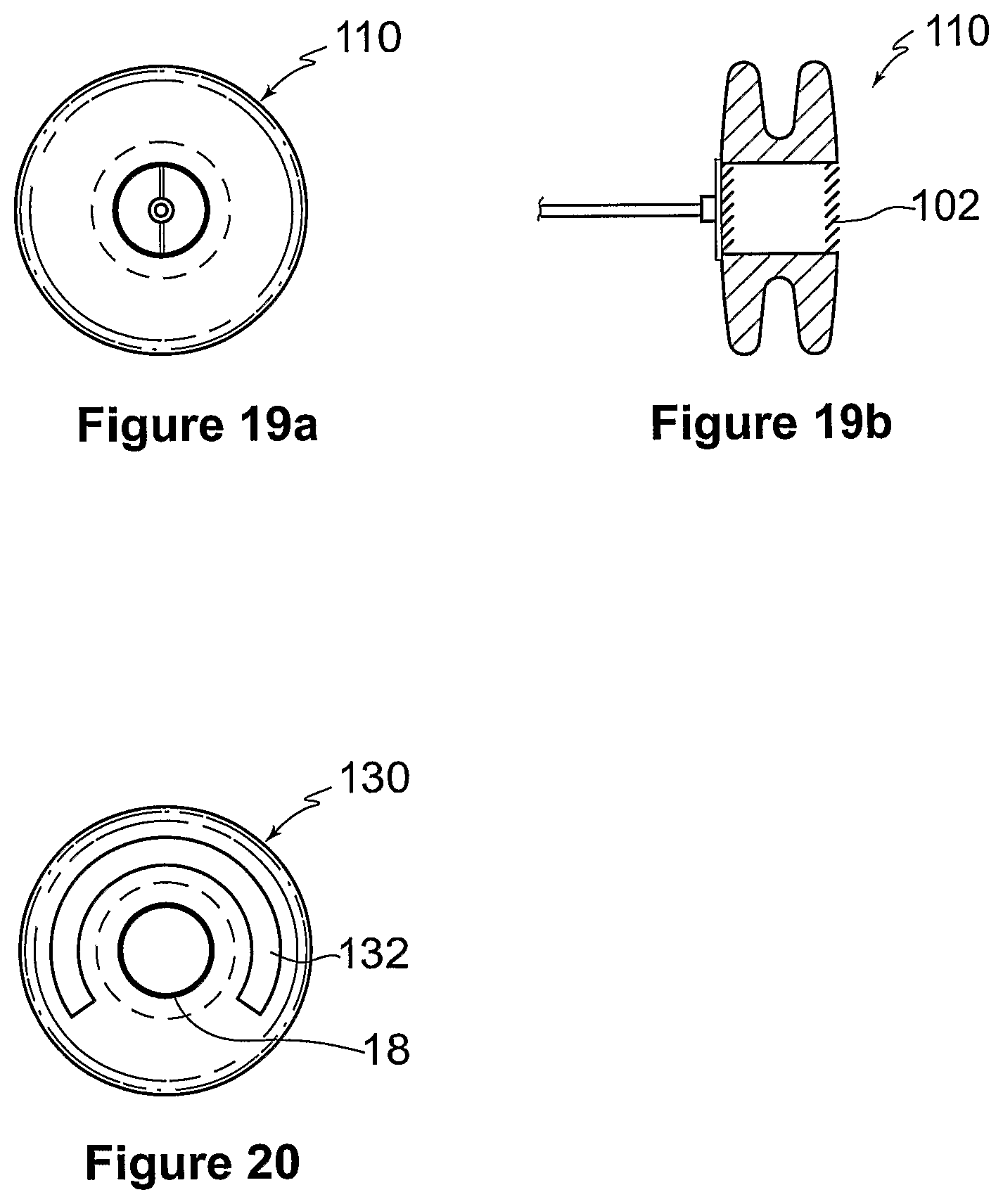
FIG. 19a is a front view of a ninth embodiment of a device for treating heart failure;
FIG. 19b is a cross sectional side view the device shown in FIG. 19a;
FIG. 20 is a front view of a tenth embodiment of a device for treating heart failure,
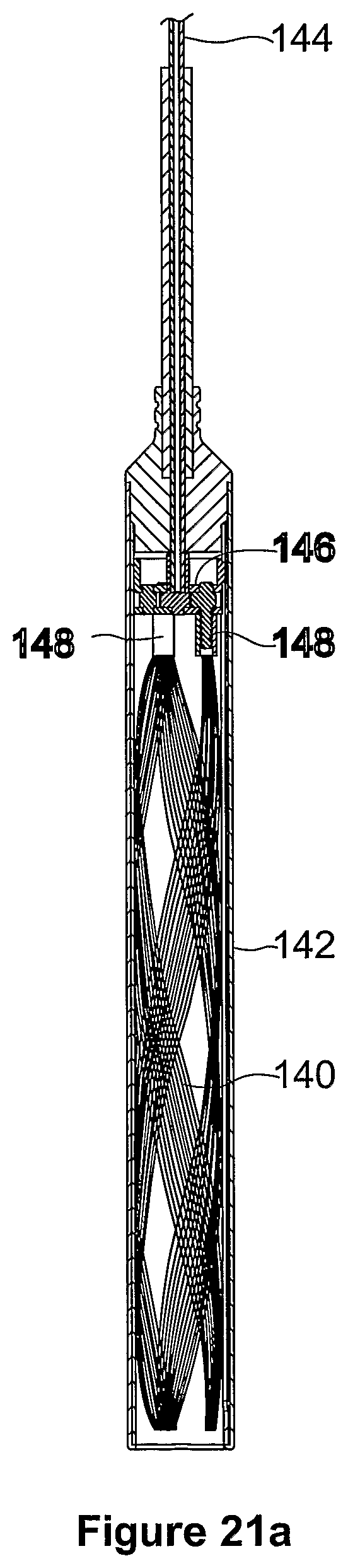
FIG. 21a is a cross sectional side view of an eleventh embodiment of a device for treating heart failure, collapsed within a catheter;
FIG. 21b is a cross sectional perspective view of the device shown in FIG. 21a, collapsed within a catheter;
FIG. 22a is a cross sectional side view of the device shown in FIG. 21a, partially deployed from the catheter;
FIG. 22b is a cross sectional perspective view of the device shown in FIG. 21a, partially deployed from the catheter;
FIG. 22c is an enlarged, partial cross sectional side view of the device shown in FIG. 21a, partially deployed from the catheter;
FIG. 23a is a side view of the device shown in FIG. 21a, deployed from the catheter;
FIG. 23b is a cross sectional side view of the device shown in FIG. 21a, deployed from the catheter; and
FIG. 24 is a cross sectional side view of a twelfth embodiment of a device for treating heart failure.
DETAILED DESCRIPTION OF THE PREFERRED EMBODIMENTS
FIGS. 1 to 4 show a first embodiment of a device 10 for treating heart failure. The device 10 includes a generally cylindrical body 12 with a mounting means, in the form of a pair of annular flanges 14 at either end with an annular gap 16 therebetween. The body 12 has a centrally located passage or duct 18 within which is provided a one way valve 20, in the form of three flexible valve leaflets 20a to 20c.
The external diameters of the body 12, the flanges 14 and internal diameter of the passage 18 are approximately 18, 38 and 12 mm respectively. In other embodiments (not shown), the diameter of the body 12 ranges from 8 to 25 mm, the diameter of the flanges 14 ranges from 20 to 50 mm, and the diameter of the passage 18 ranges from 4 to 15 mm,
FIG. 3 shows a patient's heart 22 with a left atrium 24 and a right atrium 26 separated by an atrial septum 28. The device 10 is mounted within a generally circular opening 30 made in the septum 28 and with the edges of the septum 28 adjacent the opening 30 positioned in the gap 16 between the flanges 14. The opening 30 has an internal diameter approximately equal to the external diameter of the body 12. The device 10 is retained adjacent the opening 30 in the septum 28 as the flanges 14 are larger, and thus cannot pass through, the opening 30. Alternatively, or in addition, one or both of the flanges 14 can be glued, sutured, stapled or pinned to the patient's septum 28 to secure the device 10 thereto.
The device 10 can be implanted during open heart surgery or percutaneously using a catheter. In either case, the opening 30 is firstly fashioned in the patient's atrial septum 28. Some or all of the device 10 is then collapsed to a size able to pass through the opening 30 and subsequently expanded to the configuration shown in FIG. 3. Forming the body 12 and the flanges 14 of the device 10 from a Nitinol wire mesh result in it being suitable for implanting in a manner similar to the implanting of the AMPLATZER (Trade Mark) septal occluder produced by AGA Medical Corp. More particularly, the exterior faces of the flanges 14 are pulled away from one another which causes the device 10 to lengthen and simultaneously reduce in diameter for fitting within a catheter able to pass through the opening 30. When the separating force is then removed the flanges 14 return to the (expanded) configuration in FIGS. 1 to 4.
The device 10 is orientated during implanting with the one way valve 20 only allowing blood flow through the passage 18 from the left atrium 24 to the right atrium 26, as indicated by arrows 32. More particularly, when the left atrial pressure exceeds the right atrial pressure by about 5-15 mm Hg, the valve leaflets 20a to c separate and thus open the passage 18 to blood flow from the left atrium 24 to the right atrium 26.
The leaflets 20a to 20c are formed from biological, mechanical or engineered tissue and are inherently biased towards a closed position. Further, the patient's right atrial pressure exceeding the left atrial pressure also assists in the closing, and the maintaining closed, of the valve 20.
The relief and/or avoidance of the left atrial pressure significantly exceeding the right atrial pressure is beneficial in alleviating the adverse consequences of left atrial hypertension complicating cardiovascular diseases, including left ventricular systolic and/or diastolic dysfunction and/or valvular diseases.
As best seen in FIG. 4, the device 10 includes four thin collapsible struts 34 connected to a central fixture or boss 36 having an internally threaded opening. A cable (not shown) is threadedly attachable to the fixture 36. The fixture 36 is accessible from the left atrium.
To implant the device 10, it is firstly collapsed inside a catheter. When the catheter is correctly positioned adjacent the opening 30, the cable is used to push the device 10 out of the catheter, whereafter it expands to the shape shown in FIG. 3. The cable is then unscrewed from the fixture 36 and removed from the patient with the catheter.
The device 10 can also be adapted to allow later removal by a percutaneous route, for example by the placement of small hooks (not shown) on a surface of the device 10 that is closest to a nearby venous access site.
FIG. 5 shows a second embodiment of a device 40 for treating heart failure. The construction, function and implanting of the device 40 is similar to that of the device 10 and like reference numerals are used to indicate like features between the two embodiments. However, the device 40 has four eccentrically located passages 18 through the body 12 and blood flow therethrough is controlled by four corresponding sets of valve leaflets 20.
FIGS. 6 and 7 show a third embodiment of a device 50 for treating heart failure. The construction, operation and implantation of the device 50 is similar to that of the device 10 and like reference numerals are used to indicate like features between the two embodiments. However, the device 50 has only one collapsible strut 34 connected to a central fixture 36, to which a cable 52 can be attached. The fixture 36 is also accessible from the left atrium. In a variation of this embodiment, the fixture is accessible from the right atrium.
FIGS. 8 and 9 show a fourth embodiment of a device 60 for treating heart failure. The construction, function and implanting of the device 60 is similar to that of the device 10 and like reference numerals are used to indicate like features between the two embodiments. However, the device 60 has three fixtures 36 attached to the body 12, adjacent the passage 18, to which three respective cables 62 (see FIG. 9) can be attached. The fixtures 36 are accessible from the right atrium.
FIGS. 10 and 11 show a fifth embodiment of a device 70 for treating heart failure, in a manner similar to that of the device 10. However, unlike the earlier embodiments, the device 70 only has a single mounting flange 14 which, as shown in FIG. 11, makes it suitable for implanting in the inferior vena cava 72 at or near the junction with the right atrium 74. The device 70 is preferably produced from a deformable material that can resume its preformed shape (such as Nitinol) and may be implanted by a percutaneous approach.
More particularly, the device 70 is collapsed and introduced in the venous system within a sheath, and removed from the sheath to expand when correctly positioned.
FIGS. 12 and 13 show two mechanisms suitable for delivering the device 70 to the inferior vena cava. The mechanism shown in FIG. 12 is similar to that shown in FIGS. 6 and 7 and the mechanism shown in FIG. 13 is similar to that shown in FIGS. 8 and 9.
FIG. 14 is a cross sectional side view of a sixth embodiment of a device 80 for treating heart failure, implanted in a patient's hepatic vein 82. The device 80 does not include any mounting flanges and it's body is instead an expandable stent 84 with a one way valve 20 therein.
FIG. 15 shows an alternative implanting of the device 80 in a patient's iliac veins 84 and 86.
The device 80 is also suitable for placement in the venous system of the lower limb or iliac system to relieve the signs or symptoms of lower limb hypertension (e.g. peripheral oedema and/or varicose veins).
FIG. 16 shows a seventh embodiment of a device 90 for treating heart failure. The construction, function and implanting of the device 90 is similar to that of the device 40 and like reference numerals are used to indicate like features between the two embodiments. However, the device 90 has only two eccentrically located passages 18 through the body 12 and blood flow therethrough is controlled by two corresponding sets of valve leaflets 20.
FIG. 17 shows an eighth embodiment of a device 100 for treating heart failure. This embodiment is constructed and implanted in a similar manner to that previously described. However, the device 100 has a passage 18 therethrough with a mesh or grill arrangement 102 across each end of the passage 18. The mesh 102 has apertures 104 therein of a maximum dimension of less than 4 mm which permit the flow of blood from the left to the right atrium through the passage 18, whilst substantially excluding thrombi. The mesh 102 is coated or impregnated with one or more drugs, adapted for preventing thrombosis or endothelialisation of the opening in the patient's atrial septum, including an anticoagulant substance, such as heparin, or an inhibitor of re-endthelialisation, such as sirolimus or paclitaxel
FIGS. 19a and 19b show a ninth embodiment of a device 110 for treating heart failure. The construction, operation and implantation of the device 110 is similar to that of the device 10 and like reference numerals are used to indicate like features between the two embodiments. The device 110 utilizes a strut/fixture arrangement similar to that shown in FIGS. 6 and 7.
FIG. 20 shows a tenth embodiment of a device 130 for treating heart failure. The construction, operation and implantation of the device 130 is similar to that of the device 10 and like reference numerals are used to indicate like features between the two embodiments. The device 130 has a helical groove 132 for releasably engaging a corresponding fitting on the end of a catheter cable during implantation.
FIGS. 21a to 23b show an eleventh embodiment of a device 140 for treating heart failure. The construction, operation and implantation of the device 100 is similar to that of the device 10 and like reference numerals are used to indicate like features between the two embodiments. The body 12 and the flanges 14 of the device 140 are formed from a Nitinol wire mesh which result in it being suitable for implanting in a manner similar to the implanting of the AMPLATZER (Trade Mark) septal occluder produced by AGA Medical Corp. The device 140 is collapsed by pulling the exterior faces of the flanges 14 away from one another which causes the device 140 to lengthen and simultaneously reduce in diameter. When the separating force is removed the flanges 14 return to the (expanded) configuration.
More particularly, as shown in FIGS. 21a and 21b, the device 140 is initially collapsed within a catheter 142 of about 5 mm in diameter, which is able to pass through an opening in the septum. As shown in FIGS. 22a to 22c, the device 140 is then partially deployed from the catheter 142 by movement of wire 144, and thus head 146, relative to the catheter 142. This results in part of the device 140 expanding to form the first flange 14.
As shown in FIGS. 23a and 23b, fall deployment of the device 140 by further relative movement of the wire 144 and the head 146, relative to the catheter 142, results in the remainder of the device 140 expanding to form the second flange 14. The device 140 is initially attached to the head 146 by three pins 148, which are remotely released after the device has been deployed from the catheter 142.
In other similar embodiments (not shown) the catheter 142 has a diameter of 4-6 mm and the device 140 is initially attached to the head 146 by one or two releasable pins 148.
FIG. 20 shows a twelfth embodiment of a device 150 for treating heart failure. In this embodiment, a tube 152 of about 8 mm internal diameter provides an external fluid communication path between the heart's left and right atriums 154 and 156 respectively. A valve 158 is adapted to selectively occlude the tube 152. As with earlier embodiments, when the left atrial pressure exceeds the right atrial pressure by about 5-15 mm Hg, the valve 158 is released to open the interior of the tube 152 and allow blood flow from the left atrium 24 to the right atrium 26. In a variation of this embodiment, the valve 158 is a one way valve that prevents blood flow from the right atrium 156 to the left atrium 154.
Although the invention has been described with reference to the specific examples it will be appreciated by those skilled in the art that the invention may be embodied in many other forms.
* * * * *
References
D00000
D00001
D00002
D00003
D00004
D00005
D00006
D00007
D00008
D00009
D00010
D00011
D00012

D00013

D00014

XML
uspto.report is an independent third-party trademark research tool that is not affiliated, endorsed, or sponsored by the United States Patent and Trademark Office (USPTO) or any other governmental organization. The information provided by uspto.report is based on publicly available data at the time of writing and is intended for informational purposes only.
While we strive to provide accurate and up-to-date information, we do not guarantee the accuracy, completeness, reliability, or suitability of the information displayed on this site. The use of this site is at your own risk. Any reliance you place on such information is therefore strictly at your own risk.
All official trademark data, including owner information, should be verified by visiting the official USPTO website at www.uspto.gov. This site is not intended to replace professional legal advice and should not be used as a substitute for consulting with a legal professional who is knowledgeable about trademark law.