Multi-functional shower
Yin , et al.
U.S. patent number 10,618,064 [Application Number 16/011,073] was granted by the patent office on 2020-04-14 for multi-functional shower. This patent grant is currently assigned to XIAMEN SOLEX HIGH-TECH INDUSTRIES CO., LTD.. The grantee listed for this patent is XIAMEN SOLEX HIGH-TECH INDUSTRIES CO., LTD.. Invention is credited to Bin Cao, Zhaojin Yin, Mingfu Zhang, Huasong Zhou.


| United States Patent | 10,618,064 |
| Yin , et al. | April 14, 2020 |
Multi-functional shower
Abstract
A multi-functional shower includes body unit, a switch unit, a rain shower unit, a head shower unit and a connecting pipe. The body unit has connecting portion to connect a straight portion and a sloping portion. The rain shower unit is disposed inside the straight portion, and the switch unit and the head shower unit are disposed inside the sloping portion, the connecting pipe is disposed inside the connecting portion and is connected to the switch unit and the rain shower unit. The body unit is disposed with an inlet waterway. By rotating the switch unit, the inlet waterway is connected to the rain shower unit or the head shower unit, or is connected to the rain shower unit and the head shower unit at the same time, making water flow out of the rain shower unit or the head shower unit or both at the same time, respectively.
| Inventors: | Yin; Zhaojin (Fujian, CN), Zhang; Mingfu (Fujian, CN), Cao; Bin (Fujian, CN), Zhou; Huasong (Fujian, CN) | ||||||||||
|---|---|---|---|---|---|---|---|---|---|---|---|
| Applicant: |
|
||||||||||
| Assignee: | XIAMEN SOLEX HIGH-TECH INDUSTRIES
CO., LTD. (Xiamen, CN) |
||||||||||
| Family ID: | 49803740 | ||||||||||
| Appl. No.: | 16/011,073 | ||||||||||
| Filed: | June 18, 2018 |
Prior Publication Data
| Document Identifier | Publication Date | |
|---|---|---|
| US 20180297044 A1 | Oct 18, 2018 | |
Related U.S. Patent Documents
| Application Number | Filing Date | Patent Number | Issue Date | ||
|---|---|---|---|---|---|
| 14103275 | Dec 11, 2013 | 10016769 | |||
Foreign Application Priority Data
| Jul 4, 2013 [CN] | 2013 2 0396769 U | |||
| Current U.S. Class: | 1/1 |
| Current CPC Class: | B05B 1/185 (20130101); B05B 1/1654 (20130101); B05B 12/002 (20130101) |
| Current International Class: | B05B 1/18 (20060101); B05B 1/16 (20060101); B05B 12/00 (20180101) |
| Field of Search: | ;239/391-394,396,397,442-444,446-449,540,558-563,581.1 ;137/625.46 |
References Cited [Referenced By]
U.S. Patent Documents
| 4752975 | June 1988 | Yates |
| 6742725 | June 2004 | Fan |
| 7299510 | November 2007 | Tsai |
| 2006/0138253 | June 2006 | Petrovic |
| 2009/0289129 | November 2009 | Qiu |
| 2010/0320290 | December 2010 | Luettgen |
| 2012/0325353 | December 2012 | Zhou |
| 2013/0032647 | February 2013 | Zhou |
Attorney, Agent or Firm: Cooper Legal Group, LLC
Parent Case Text
CROSS-REFERENCE TO RELATED APPLICATION
This is a continuation of U.S. application Ser. No. 14/103,275, filed on Dec. 11, 2013, and allowed on Mar. 13, 2018, the subject matter of which is incorporated herein by reference. The disclosures of these prior U.S. and foreign applications are incorporated herein by reference.
Claims
What is claimed is:
1. A multi-functional shower, comprising: a body unit comprising a housing including a straight portion, a sloping portion fixed in place relative to the straight portion and a connecting portion connecting the straight portion and the sloping portion, wherein the body unit includes an inlet waterway; a rain shower unit disposed inside the straight portion; a head shower unit disposed inside the sloping portion; a switch unit rotatably disposed inside the sloping portion, wherein: a rain shower water cavity is formed in the switch unit, two head shower water cavities are formed in the switch unit, the switch unit has a rain shower inlet selectively connecting the inlet waterway and the rain shower water cavity together, each of two head shower inlets selectively connects the inlet waterway and a respective one of the two head shower water cavities together, the switch unit has a rain shower outlet connected to the rain shower water cavity, a first one of the two head shower water cavities discharges a first water flow, a second one of the two head shower water cavities discharges a second water flow different from the first water flow, the switch unit controls flow to both the head shower unit and the rain shower unit; and a connecting pipe disposed inside the connecting portion and connecting the switch unit and the rain shower unit together wherein, by rotating the switch unit; the inlet waterway is connected to the rain shower unit or the head shower unit, or the inlet waterway is connected to the rain shower unit and the head shower unit at a same time.
2. The multi-functional shower according to claim 1, further comprising: a switch configured to drive the switch unit to rotate, wherein the switch is connected to the head shower unit.
3. The multi-functional shower according to claim 2, wherein the switch is disposed in an outlet surface of the head shower unit.
4. The multi-functional shower according to claim 3, wherein the switch is configured to be pushed to drive the switch unit to rotate.
5. The multi-functional shower according to claim 3, wherein the switch is configured to be pressed to drive the switch unit to rotate.
6. The multi-functional shower according to claim 3, wherein the switch is configured to be rotated to drive the switch unit to rotate.
7. The multi-functional shower according to claim 1, further comprising: a water diversion dish, wherein: the water diversion dish is disposed inside the sloping portion, the water diversion dish and the body unit form a water cavity, the inlet waterway is connected to the water cavity, the water diversion dish has a first through hole and a second through hole, the water diversion dish abuts the switch unit, the first through hole is connected to or disconnected from the rain shower inlet of the rain shower water cavity, the second through hole is connected to or disconnected from at least one of the two head shower inlets of the two head shower water cavities.
8. The multi-functional shower according to claim 7, wherein: the rain shower water cavity includes a first rain shower water cavity, a second rain shower water cavity, and a third rain shower water cavity, a first head shower water cavity of the two head shower water cavities has a first head shower inlet of the two head shower inlets and a second head shower water cavity of the two head shower water cavities has a second head shower inlet of the two head shower inlets, the first head shower inlet of the first head shower water cavity has a first entrance and a second entrance, the second head shower inlet of the second head shower water cavity has a first inlet and a second inlet, and when rotating the switch unit: the first through hole is connected to the first rain shower water cavity and the second through hole is cut off; or the first through hole is cut off and the second through hole is connected to the first entrance; or the first through hole is connected to the second rain shower water cavity and the second through hole is connected to the second entrance; or the first through hole is cut off and the second through hole is connected to the second entrance and the first inlet; or the first through hole is connected to the third rain shower water cavity and the second through hole is connected to the first inlet; or the first through hole is cut off and the second through hole is connected to the second inlet.
9. The multi-functional shower according to claim 8, wherein: the first head shower water cavity is configured to discharge the first water flow, and the second head shower water cavity is configured to discharge the second water flow.
10. The multi-functional shower according to claim 8, wherein: the rain shower inlet is in a top portion of the switch unit and includes: a first rain shower inlet connected to the first rain shower water cavity, a second rain shower inlet connected to the second rain shower water cavity, and a third rain shower inlet connected to the third rain shower water cavity, and when rotating the switch unit: the first through hole is selectively connected to one of the first rain shower inlet, the second rain shower inlet or the third rain shower inlet, or the first through hole is disconnected from all of the first rain shower inlet, the second rain shower inlet and the third rain shower inlet.
11. The multi-functional shower according to claim 8, further comprising: a setting base entirely disposed inside the body unit, wherein: the rain shower outlet of the switch unit is rotatably connected to the setting base, wherein: the rain shower outlet is in a side portion of the switch unit and includes: a first rain shower outlet connected to the first rain shower water cavity, a second rain shower outlet connected to the second rain shower water cavity, and a third rain shower outlet connected to the third rain shower water cavity, and the switch unit is rotatably connected to the setting base as so to selectively connect one of the first rain shower outlet, the second rain shower outlet or the third rain shower outlet to the setting base or so as to disconnect all of the first rain shower outlet, the second rain shower outlet and the third rain shower outlet from the setting base.
Description
FIELD OF THE INVENTION
The present invention relates to a multi-functional shower.
BACKGROUND OF THE INVENTION
Showers can be divided into rain showers (or named sunflower showers) and head shower (or named head sprayer). The rain shower is assembled at the top surface of the bathroom, and is right above user's head and directly discharges water to user's head in the outlet direction; the head shower is assembled on the wall of the bathroom, and is inclined above user's head and discharges water to user's face in the outlet direction.
Currently the bathroom usually assembles with rain shower and head shower both for different users' needs. Therefore, the bathroom has to assemble connecting pipes for the rain shower and the head shower, which is troublesome in waterway design and high in fixture cost.
SUMMARY OF THE INVENTION
The present invention is provided with a multi-functional shower, which overcomes the disadvantages of the background technology. The technical proposal of the present invention is:
A multi-functional shower, which comprises a body unit and a switch unit, further comprising a rain shower unit, a head shower unit and a connecting pipe, the body unit comprising a straight portion, a sloping portion and a connecting portion connecting the straight portion and the sloping portion, the rain shower unit is disposed inside the straight portion, the switch unit and the head shower unit are disposed inside the sloping portion, the connecting pipe is disposed inside the connecting portion and is connected the switch unit and the rain shower unit, the body unit is disposed with an inlet waterway, by rotating the switch unit, the inlet waterway is connected to the rain shower unit or the head shower unit, or is connected to the rain shower unit and the head shower unit at the same time.
In another preferred embodiment, it further comprising a switch to drive the switch unit to rotate, the switch is connected to the head shower unit.
In another preferred embodiment, the switch is disposed in the outlet surface of the head shower unit.
In another preferred embodiment, the switch is applied with push type to drive the switch to rotate.
In another preferred embodiment, the switch is applied with press type to drive the switch unit to rotate.
In another preferred embodiment, the switch is applied with knob type to drive the switch unit to rotate.
In another preferred embodiment, it further comprising a water diversion dish, the water diversion dish is disposed inside the sloping portion, the water diversion dish and the body unit form a water cavity, the inlet waterway is connected to the water cavity, the water diversion dish is disposed with a first through hole and a second through hole, the switch unit comprising a rain shower water cavity and a head shower water cavity, the water diversion dish abuts against the switch unit, the first through hole is connected to the rain shower water cavity or disconnected, the second through hole is connected to the head shower water cavity or disconnected.
In another preferred embodiment, the body unit is disposed with a setting base inside, one end of the connecting pipe is connected to the rain shower unit, the other end of the connecting pipe is connected to the setting base, the setting base is slidably connected to the switch unit in sealing way, the switch unit, when rotating, makes that the rain shower water cavity is alternately connected to the setting base or disconnected.
In another preferred embodiment, it comprising three rain shower water cavities and two head shower water cavities, a first rain shower water cavity, a second rain shower water cavity, a third rain shower water cavity, a first head shower water cavity and a second head shower water cavity; the first head shower water cavity is disposed with a first entrance and a second entrance, the second head shower water cavity is disposed with a first inlet and a second inlet;
when rotating the switch unit:
the first through hole is connected to the first rain shower water cavity, the second through hole is cut off; or
the first through hole is cut off, the second through hole is connected to the first entrance; or
the first through hole is connected to the second rain shower water cavity, the second through hole is connected to the second entrance; or
the first through hole is cut off, the second through hole is connected to the second entrance and the first inlet; or
the first through hole is connected to the third rain shower water cavity, the second through hole is connected to the first inlet; or
the first through hole is cut off, the second through hole is connected to the second inlet.
In another preferred embodiment, the first head shower water cavity is used to discharge head shower water, the second head shower water cavity is used to discharge head shower massage water.
Compared to the existing technology, the technical proposal of the present invention has advantages as below:
1. the shower comprises a rain shower unit and a head shower unit, by rotating the switch unit, water flows out of the rain shower unit or the head shower unit or both at the same time, the bathroom is just needed to assemble with one inlet waterway, thus reducing the assembly cost.
2. the body unit is disposed with a setting base inside, the other end of the connecting pipe is connected to the setting base, the setting base is slidably connected to the switch unit in sealing way, the connecting pipe would not move with the moving of the switch unit, thus making it with stable structure.
BRIEF DESCRIPTION OF THE DRAWINGS
The present invention will be further described with the drawings and the embodiments.
FIG. 1 illustrates a schematic diagram of the multi-functional shower of the present invention.
FIG. 2 illustrates a front view of the multi-functional shower of FIG. 1.
FIG. 3 illustrates an exploded diagram of the multi-functional shower of FIG. 1.
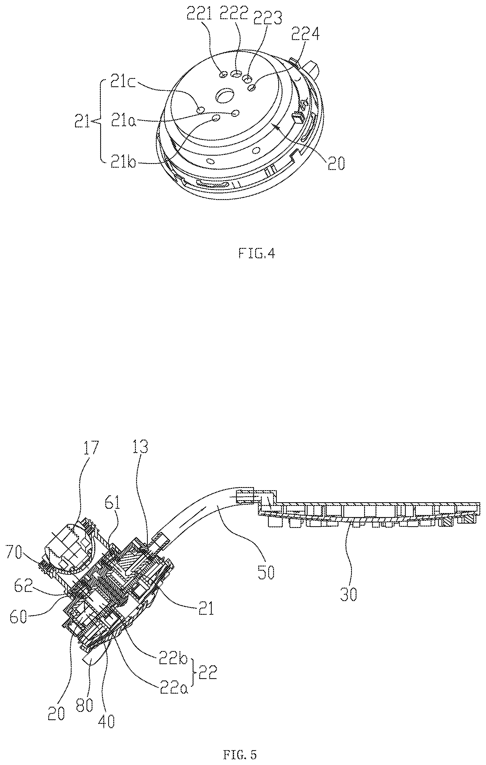
FIG. 4 illustrates a schematic diagram of the switch unit of the multi-functional shower of FIG. 1.
FIG. 5 illustrates a partial sectional view of the multi-functional shower of FIG. 1.
FIG. 6 illustrates a schematic diagram of a second embodiment of the multi-functional shower of the present invention.
FIG. 7 illustrates a schematic diagram of a third embodiment of the multi-functional shower of the present invention.
DETAILED DESCRIPTION OF THE EMBODIMENTS
Please refer to FIG. 1 to FIG. 5, a multi-functional shower of the present invention comprising a body unit 10, a switch unit 20, a rain shower unit 30, a head shower unit 40, a connecting pipe 50, a water diversion dish 60 and a switch 80.
The body unit 10 comprises an upper cover 11, a lower cover 12 and a setting base 13. When the upper cover covers the lower cover, it forms a hollow housing structure. The body unit 10 comprises a straight portion 14, a sloping portion 15 and a connecting portion 16 connecting the straight portion 14 and the sloping portion 15. The straight portion 14 generally has a horizontal body. The setting base 13 is disposed inside the connecting portion 16. The sloping portion 15 of the body unit 10 has an inlet waterway 17 (as figured in FIG. 5).
The switch unit 20 is used to make that the inlet waterway 17 is connected to the rain shower unit 30 or the head shower unit 40, or that the inlet waterway 17 is connected to the rain shower unit 30 and the head shower unit 40 both. The switch unit 20 has a rain shower water cavity 21 and a head shower water cavity 22 inside. The rain shower water cavity 21 is used to supply water to the rain shower unit 30. The head shower water cavity 22 is used to supply water to the head shower unit 40. There are three rain shower water cavities 21, a first rain shower water cavity 21a, a second rain shower water cavity 21b and a third rain shower water cavity 21c. The first rain shower water cavity 21a, the second rain shower water cavity 21b and the third rain shower water cavity 21c are spaced arranged, the central directions of the first, the second and the third rain shower water cavity to the switch unit 20 are equal. There are two head shower water cavities 22, a first head shower water cavity 22a and a second head shower water cavity 22b. The first head shower water cavity 22a is disposed with a first entrance 221 and a second entrance 222. The second head shower water cavity 22b is disposed with a first inlet 223 and a second inlet 224. The first entrance 221, the second entrance 222, the first inlet 223 and the second inlet 224 are spaced arranged, the central directions of the first entrance 221, the second entrance 222, the first inlet 223 and the second inlet 224 to the switch unit 20 are equal. The first head shower water cavity 22a is used to discharge head shower water. The second head shower water cavity 22b is used to discharge massage water.
When the rain shower unit 30 is connected to the inlet waterway 17, it discharges rain shower water.
When the head unit 40 is connected to the inlet waterway 17, it discharges head shower water or head shower massage water.
The water diversion dish 60 is disposed with a first through hole 61 and a second through hole 61. The first through hole 61 is used to connect the inlet watery 17 and the rain shower water cavity 21. The second through hole 62 is used to connect the inlet waterway 17 and the head shower water cavity 22.
The switch 80 is used to drive the switch unit 20 to rotate. The switch 80 is applied with a push type to drive the switch unit to rotate.
The rain shower unit 30 is disposed inside the straight portion 14; the switch unit 20 and the head shower unit 40 are disposed inside the sloping portion 15, the switch unit 20 is rotatably disposed on the head shower 40, the setting base 13 is slidably connected to the switch unit 20 in sealing way; the connecting pipe 50 is disposed inside the connecting portion 16, one end of the connecting pipe 50 is connected to the rain shower unit 30, while the other end is connected to the setting base 13, the switch unit 20, when rotating, alternately makes the rain shower water cavity 21 connected to the setting base 13 or disconnected, that is to say, the connecting pipe 50 is able to connected to the switch unit 20 and the rain shower unit 30; the water diversion dish 60 is disposed inside the sloping portion 15, the water diversion dish 60 and the body unit 10 form a water cavity 70. The inlet waterway 17 is connected to the water cavity 70. the water diversion dish 60 abuts against the switch unit 20. The first through hole 61 and the rain shower water cavity 21 are disposed in alignment, thus making the water cavity 70 connected to the rain shower water cavity 21 or disconnected. The second through hole 62 is aligned with the first entrance 221, the second entrance 222, the first inlet 223 and the second inlet 224, thus making the water cavity 70 connected to the head shower water cavity 22 or disconnected. The switch 80 is connected to the head shower unit 40, and the switch 80 is disposed on the outlet surface of the head shower unit 40.
To switch waterway, dial the switch unit 80 so that the switch 80 drives the switch unit 20 to rotate;
When the first through hole 61 is connected to the first rain shower water cavity 21a, and the second through hole 62 is cut off, only the rain shower unit 30 discharges rain shower water. That is to say, water flows through the inlet waterway 17, the water cavity 70, the first through hole 61, the first rain shower water cavity 21a, the setting base 13, the connecting pipe, and then out of the rain shower unit 30;
When the first through hole 61 is cut off and the second through hole 62 is connected to the first entrance 221, only the head shower unit 40 discharges head shower water. That is to say, water flows through the inlet waterway 17, the water cavity 70, the second through hole 62, the first entrance 221, the first head shower water cavity 22a, and then out of the head shower unit 40;
When the first through hole 61 is connected to the second rain shower water cavity 21b, and the second through hole 62 is connected to the second entrance 222, the rain shower unit 30 discharges rain shower water, the head shower unit 40 discharges head shower water. That is to say, there are two water flows, one flows through the inlet waterway 17, the water cavity 70, the first through hole 61, the second rain shower water cavity 21b, the setting base 13, the connecting pipe 50, and then out of the rain shower unit 30; the other one flows through the inlet waterway 17, the water cavity 70, the second through hole 62, the second entrance 222, the first head shower water cavity 22a, then out of the head shower unit 40;
When the first through hole 61 is cut off, and the second through hole 62 is connected to the first entrance 222 and the first inlet 223, the head shower unit 40 discharges head shower water and head shower massage water. That is to say, water flows through the inlet waterway 17, the water cavity 70, the second through hole 62, the second entrance 222 and the first inlet 223, the first head shower water cavity 22a and the second head shower water cavity 22b, then out of the head shower unit 40;
When the first through hole 61 is connected to the third rain shower water cavity 21c, and the second through hole 62 is connected to the first inlet 223, the rain shower unit 30 discharges rain shower water, the head shower unit 40 discharges head shower massage water. That is to say, there are two water flows, one flows through the inlet waterway 17, the water cavity 70, the first through hole 61, the third rain shower water cavity 21c, the setting base 13, the connecting pipe 50, and then out of the rain shower unit 30; the other one flows through the inlet waterway 17, the water cavity 70, the second through hole 62, the first inlet 223, the second head shower water cavity 22b, then out of the head shower unit 40;
When the first through hole 61 is cut off, and the second through hole is connected to the second inlet 224, only the head shower unit 40 discharges head shower massage water. That is to say, water flows through the inlet waterway 17, the water cavity 70, the second through hole 62, the second inlet 224, the second head shower water cavity 22b, then out of the head shower unit 40.
Please refer to FIG. 6, the difference of this embodiment of the present invention from the first embodiment is that the switch 80a is applied with a press type to drive the switch unit to rotate, that is to say, by pushing vertically the switch 80a, the switch unit rotates.
Please refer to FIG. 7, the difference of this embodiment of the present invention from the first embodiment is that the switch 80b is applied with a knob to drive the switch unit to rotate, that is to say, by turning the knob switch 80b, the switch unit rotates.
Although the present invention has been described with reference to the preferred embodiments thereof for carrying out the patent for invention, it is apparent to those skilled in the art that a variety of modifications and changes may be made without departing from the scope of the patent for invention which is intended to be defined by the appended claims.
* * * * *
D00000
D00001
D00002
D00003
D00004
XML
uspto.report is an independent third-party trademark research tool that is not affiliated, endorsed, or sponsored by the United States Patent and Trademark Office (USPTO) or any other governmental organization. The information provided by uspto.report is based on publicly available data at the time of writing and is intended for informational purposes only.
While we strive to provide accurate and up-to-date information, we do not guarantee the accuracy, completeness, reliability, or suitability of the information displayed on this site. The use of this site is at your own risk. Any reliance you place on such information is therefore strictly at your own risk.
All official trademark data, including owner information, should be verified by visiting the official USPTO website at www.uspto.gov. This site is not intended to replace professional legal advice and should not be used as a substitute for consulting with a legal professional who is knowledgeable about trademark law.