Anvil assembly with frangible retaining member
Williams , et al.
U.S. patent number 10,595,870 [Application Number 15/387,794] was granted by the patent office on 2020-03-24 for anvil assembly with frangible retaining member. This patent grant is currently assigned to Covidien LP. The grantee listed for this patent is Covidien LP. Invention is credited to Steven Joyce, Patrick D. Mozdzierz, Justin Williams.
| United States Patent | 10,595,870 |
| Williams , et al. | March 24, 2020 |
Anvil assembly with frangible retaining member
Abstract
An anvil assembly includes a retaining member having a body portion and a frangible portion connected to the body portion, where the frangible portion is positioned to engage a backup member and separates from the body portion during movement of the backup member from a first, proximal position to a second, distal position. The retaining member keeps the backup plate in the proximal position prior to firing of the stapling assembly, and upon separation of the frangible portion allows the backup plate to move to the distal position during firing of the stapling assembly. Proximal force on the backup plate after firing of the stapling assembly is avoided, thereby helping to ensure titling of the anvil assembly.
| Inventors: | Williams; Justin (Southbury, CT), Mozdzierz; Patrick D. (Glastonbury, CT), Joyce; Steven (Wallingford, CT) | ||||||||||
|---|---|---|---|---|---|---|---|---|---|---|---|
| Applicant: |
|
||||||||||
| Assignee: | Covidien LP (Mansfield,
MA) |
||||||||||
| Family ID: | 51932195 | ||||||||||
| Appl. No.: | 15/387,794 | ||||||||||
| Filed: | December 22, 2016 |
Prior Publication Data
| Document Identifier | Publication Date | |
|---|---|---|
| US 20170100124 A1 | Apr 13, 2017 | |
Related U.S. Patent Documents
| Application Number | Filing Date | Patent Number | Issue Date | ||
|---|---|---|---|---|---|
| 14078766 | Nov 13, 2013 | 9554802 | |||
| Current U.S. Class: | 1/1 |
| Current CPC Class: | A61B 17/1155 (20130101); A61B 2090/037 (20160201) |
| Current International Class: | A61B 17/115 (20060101); A61B 90/00 (20160101) |
| Field of Search: | ;227/19,175.1-182.1 ;606/139,219,153,75,220 |
References Cited [Referenced By]
U.S. Patent Documents
| 3193165 | July 1965 | Akhalaya et al. |
| 3388847 | June 1968 | Kasulin et al. |
| 3552626 | January 1971 | Astafiev et al. |
| 3638652 | February 1972 | Kelley |
| 3771526 | November 1973 | Rudie |
| 4198982 | April 1980 | Fortner et al. |
| 4207898 | June 1980 | Becht |
| 4289133 | September 1981 | Rothfuss |
| 4304236 | December 1981 | Conta et al. |
| 4319576 | March 1982 | Rothfuss |
| 4350160 | September 1982 | Kolesov et al. |
| 4351466 | September 1982 | Noiles |
| 4379457 | April 1983 | Gravener et al. |
| 4473077 | September 1984 | Noiles et al. |
| 4476863 | October 1984 | Kanshin et al. |
| 4485817 | December 1984 | Swiggett |
| 4488523 | December 1984 | Shichman |
| 4505272 | March 1985 | Utyamyshev |
| 4505414 | March 1985 | Filipi |
| 4520817 | June 1985 | Green |
| 4550870 | November 1985 | Krumme et al. |
| 4573468 | March 1986 | Conta et al. |
| 4576167 | March 1986 | Noiles |
| 4592354 | June 1986 | Rothfuss |
| 4603693 | August 1986 | Conta et al. |
| 4606343 | August 1986 | Conta et al. |
| 4632290 | December 1986 | Green et al. |
| 4646745 | March 1987 | Noiles |
| 4665917 | May 1987 | Clanton et al. |
| 4667673 | May 1987 | Li |
| 4671445 | June 1987 | Barker et al. |
| 4700703 | October 1987 | Resnick et al. |
| 4703887 | November 1987 | Clanton et al. |
| 4708141 | November 1987 | Inoue et al. |
| 4717063 | January 1988 | Ebihara |
| 4752024 | June 1988 | Green et al. |
| 4754909 | July 1988 | Barker et al. |
| 4776506 | October 1988 | Green |
| 4817847 | April 1989 | Redtenbacher et al. |
| 4873977 | October 1989 | Avant et al. |
| 4893622 | January 1990 | Green et al. |
| 4903697 | February 1990 | Resnick et al. |
| 4907591 | March 1990 | Vasconcellos et al. |
| 4917114 | April 1990 | Green et al. |
| 4929240 | May 1990 | Kirsch |
| 4957499 | September 1990 | Lipatov et al. |
| 4962877 | October 1990 | Hervas |
| 5005749 | April 1991 | Aranyi |
| 5042707 | August 1991 | Taheri |
| 5047039 | September 1991 | Avant et al. |
| 5104025 | April 1992 | Main et al. |
| 5119983 | June 1992 | Green et al. |
| 5122156 | June 1992 | Granger et al. |
| 5139513 | August 1992 | Segato |
| 5158222 | October 1992 | Green et al. |
| 5188638 | February 1993 | Tzakis |
| 5193731 | March 1993 | Aranyi |
| 5197648 | March 1993 | Gingold |
| 5197649 | March 1993 | Bessler et al. |
| 5205459 | April 1993 | Brinkerhoff et al. |
| 5221036 | June 1993 | Takase |
| 5222963 | June 1993 | Brinkerhoff |
| 5250058 | October 1993 | Miller |
| 5253793 | October 1993 | Green et al. |
| 5261920 | November 1993 | Main et al. |
| 5271543 | December 1993 | Grant et al. |
| 5271544 | December 1993 | Fox et al. |
| 5275322 | January 1994 | Brinkerhoff et al. |
| 5282810 | February 1994 | Allen et al. |
| 5285944 | February 1994 | Green et al. |
| 5285945 | February 1994 | Brinkerhoff et al. |
| 5292053 | March 1994 | Bilotti et al. |
| 5309927 | May 1994 | Welch |
| 5312024 | May 1994 | Grant et al. |
| 5314435 | May 1994 | Green et al. |
| 5314436 | May 1994 | Wilk |
| 5330486 | July 1994 | Wilk |
| 5333773 | August 1994 | Main et al. |
| 5344059 | September 1994 | Green et al. |
| 5346115 | September 1994 | Perouse et al. |
| 5348259 | September 1994 | Blanco et al. |
| 5350104 | September 1994 | Main et al. |
| 5355897 | October 1994 | Pietrafitta et al. |
| 5360154 | November 1994 | Green |
| 5368215 | November 1994 | Green et al. |
| 5392979 | February 1995 | Green et al. |
| 5395030 | March 1995 | Kuramoto et al. |
| 5403333 | April 1995 | Kaster et al. |
| 5404870 | April 1995 | Brinkerhoff et al. |
| 5411508 | May 1995 | Bessler et al. |
| 5425738 | June 1995 | Gustafson et al. |
| 5433721 | July 1995 | Hooven et al. |
| 5437684 | August 1995 | Calabrese et al. |
| 5439156 | August 1995 | Grant et al. |
| 5443198 | August 1995 | Viola et al. |
| 5447514 | September 1995 | Gerry et al. |
| 5454825 | October 1995 | Van Leeuwen et al. |
| 5464415 | November 1995 | Chen |
| 5470006 | November 1995 | Rodak |
| 5474223 | December 1995 | Viola et al. |
| 5497934 | March 1996 | Brady et al. |
| 5503635 | April 1996 | Sauer et al. |
| 5522534 | June 1996 | Viola et al. |
| 5533661 | July 1996 | Main et al. |
| 5588579 | December 1996 | Schnut et al. |
| 5609285 | March 1997 | Grant et al. |
| 5626591 | May 1997 | Kockerling et al. |
| 5632433 | May 1997 | Grant et al. |
| 5639008 | June 1997 | Gallagher et al. |
| 5641111 | June 1997 | Ahrens et al. |
| 5658300 | August 1997 | Bito et al. |
| 5669918 | September 1997 | Balazs et al. |
| 5685474 | November 1997 | Seeber |
| 5709335 | January 1998 | Heck |
| 5715987 | February 1998 | Kelley et al. |
| 5718360 | February 1998 | Green et al. |
| 5720755 | February 1998 | Dakov |
| 5732872 | March 1998 | Bolduc et al. |
| 5749896 | May 1998 | Cook |
| 5758814 | June 1998 | Gallagher et al. |
| 5799857 | September 1998 | Robertson et al. |
| 5814055 | September 1998 | Knodel et al. |
| 5833698 | November 1998 | Hinchliffe et al. |
| 5836503 | November 1998 | Ehrenfels et al. |
| 5839639 | November 1998 | Sauer et al. |
| 5855312 | January 1999 | Toledano |
| 5860581 | January 1999 | Robertson et al. |
| 5868760 | February 1999 | McGuckin, Jr. |
| 5881943 | March 1999 | Heck et al. |
| 5915616 | June 1999 | Viola et al. |
| 5947363 | September 1999 | Bolduc et al. |
| 5951576 | September 1999 | Wakabayashi |
| 5957363 | September 1999 | Heck |
| 5993468 | November 1999 | Rygaard |
| 6024748 | February 2000 | Manzo et al. |
| 6050472 | April 2000 | Shibata |
| 6053390 | April 2000 | Green et al. |
| 6068636 | May 2000 | Chen |
| 6083241 | July 2000 | Longo et al. |
| 6102271 | August 2000 | Longo et al. |
| 6117148 | September 2000 | Ravo et al. |
| 6119913 | September 2000 | Adams et al. |
| 6126058 | October 2000 | Adams et al. |
| 6131789 | October 2000 | Schulze |
| 6142933 | November 2000 | Longo et al. |
| 6149667 | November 2000 | Hovland et al. |
| 6176413 | January 2001 | Heck |
| 6179195 | January 2001 | Adams et al. |
| 6193129 | February 2001 | Bittner et al. |
| 6203553 | March 2001 | Robertson et al. |
| 6209773 | April 2001 | Bolduc et al. |
| 6241140 | June 2001 | Adams et al. |
| 6253984 | July 2001 | Heck et al. |
| 6258107 | July 2001 | Balazs et al. |
| 6264086 | July 2001 | McGuckin, Jr. |
| 6269997 | August 2001 | Balazs et al. |
| 6273897 | August 2001 | Dalessandro et al. |
| 6279809 | August 2001 | Nicolo |
| 6302311 | October 2001 | Adams et al. |
| 6338737 | January 2002 | Toledano |
| 6343731 | February 2002 | Adams et al. |
| 6387105 | May 2002 | Gifford, III et al. |
| 6398795 | June 2002 | McAlister et al. |
| 6402008 | June 2002 | Lucas |
| 6439446 | August 2002 | Perry et al. |
| 6443973 | September 2002 | Whitman |
| 6450390 | September 2002 | Heck et al. |
| 6478210 | November 2002 | Adams et al. |
| 6488197 | December 2002 | Whitman |
| 6491201 | December 2002 | Whitman |
| 6494877 | December 2002 | Odell et al. |
| 6503259 | January 2003 | Huxel et al. |
| 6517566 | February 2003 | Hovland et al. |
| 6520398 | February 2003 | Nicolo |
| 6533157 | March 2003 | Whitman |
| 6551334 | April 2003 | Blatter et al. |
| 6578751 | June 2003 | Hartwick |
| 6585144 | July 2003 | Adams et al. |
| 6588643 | July 2003 | Bolduc et al. |
| 6592596 | July 2003 | Geitz |
| 6601749 | August 2003 | Sullivan et al. |
| 6605078 | August 2003 | Adams |
| 6605098 | August 2003 | Nobis et al. |
| 6626921 | September 2003 | Blatter et al. |
| 6629630 | October 2003 | Adams |
| 6631837 | October 2003 | Heck |
| 6632227 | October 2003 | Adams |
| 6632237 | October 2003 | Ben-David et al. |
| 6652542 | November 2003 | Blatter et al. |
| 6659327 | December 2003 | Heck et al. |
| 6676671 | January 2004 | Robertson et al. |
| 6681979 | January 2004 | Whitman |
| 6685079 | February 2004 | Sharma et al. |
| 6695198 | February 2004 | Adams et al. |
| 6695199 | February 2004 | Whitman |
| 6698643 | March 2004 | Whitman |
| 6716222 | April 2004 | McAlister et al. |
| 6716233 | April 2004 | Whitman |
| 6726697 | April 2004 | Nicholas et al. |
| 6742692 | June 2004 | Hartwick |
| 6743244 | June 2004 | Blatter et al. |
| 6763993 | July 2004 | Bolduc et al. |
| 6769590 | August 2004 | Vresh et al. |
| 6769594 | August 2004 | Orban, III |
| 6820791 | November 2004 | Adams |
| 6821282 | November 2004 | Perry et al. |
| 6827246 | December 2004 | Sullivan et al. |
| 6840423 | January 2005 | Adams et al. |
| 6843403 | January 2005 | Whitman |
| 6846308 | January 2005 | Whitman et al. |
| 6852122 | February 2005 | Rush |
| 6866178 | March 2005 | Adams et al. |
| 6872214 | March 2005 | Sonnenschein et al. |
| 6874669 | April 2005 | Adams et al. |
| 6884250 | April 2005 | Monassevitch et al. |
| 6905504 | June 2005 | Vargas |
| 6938814 | September 2005 | Sharma et al. |
| 6942675 | September 2005 | Vargas |
| 6945444 | September 2005 | Gresham et al. |
| 6953138 | October 2005 | Dworak et al. |
| 6957758 | October 2005 | Aranyi |
| 6959851 | November 2005 | Heinrich |
| 6978922 | December 2005 | Bilotti et al. |
| 6981941 | January 2006 | Whitman et al. |
| 6981979 | January 2006 | Nicolo |
| 7032798 | April 2006 | Whitman et al. |
| 7059331 | June 2006 | Adams et al. |
| 7059510 | June 2006 | Orban, III |
| 7077856 | July 2006 | Whitman |
| 7080769 | July 2006 | Vresh et al. |
| 7086267 | August 2006 | Dworak et al. |
| 7114642 | October 2006 | Whitman |
| 7118528 | October 2006 | Piskun |
| 7122044 | October 2006 | Bolduc et al. |
| 7128748 | October 2006 | Mooradian et al. |
| 7141055 | November 2006 | Abrams et al. |
| 7168604 | January 2007 | Milliman et al. |
| 7179267 | February 2007 | Nolan et al. |
| 7182239 | February 2007 | Myers |
| 7195142 | March 2007 | Orban, III |
| 7207168 | April 2007 | Doepker et al. |
| 7220237 | May 2007 | Gannoe et al. |
| 7234624 | June 2007 | Gresham et al. |
| 7235089 | June 2007 | McGuckin, Jr. |
| RE39841 | September 2007 | Bilotti et al. |
| 7285125 | October 2007 | Viola |
| 7303106 | December 2007 | Milliman et al. |
| 7303107 | December 2007 | Milliman et al. |
| 7309341 | December 2007 | Ortiz et al. |
| 7322994 | January 2008 | Nicholas et al. |
| 7325713 | February 2008 | Aranyi |
| 7334718 | February 2008 | McAlister et al. |
| 7335212 | February 2008 | Edoga et al. |
| 7364060 | April 2008 | Milliman |
| 7398908 | July 2008 | Holsten et al. |
| 7399305 | July 2008 | Csiky et al. |
| 7401721 | July 2008 | Holsten et al. |
| 7401722 | July 2008 | Hur |
| 7407075 | August 2008 | Holsten et al. |
| 7410086 | August 2008 | Ortiz et al. |
| 7422137 | September 2008 | Manzo |
| 7422138 | September 2008 | Bilotti et al. |
| 7431191 | October 2008 | Milliman |
| 7438718 | October 2008 | Milliman et al. |
| 7455676 | November 2008 | Holsten et al. |
| 7455682 | November 2008 | Viola |
| 7481347 | January 2009 | Roy |
| 7494038 | February 2009 | Milliman |
| 7506791 | March 2009 | Omaits et al. |
| 7516877 | April 2009 | Aranyi |
| 7527185 | May 2009 | Harari et al. |
| 7537602 | May 2009 | Whitman |
| 7546939 | June 2009 | Adams et al. |
| 7546940 | June 2009 | Milliman et al. |
| 7547312 | June 2009 | Bauman et al. |
| 7556186 | July 2009 | Milliman |
| 7559451 | July 2009 | Sharma et al. |
| 7585306 | September 2009 | Abbott et al. |
| 7588174 | September 2009 | Holsten et al. |
| 7600663 | October 2009 | Green |
| 7611038 | November 2009 | Racenet et al. |
| 7635385 | December 2009 | Milliman et al. |
| 7669747 | March 2010 | Weisenburgh, II et al. |
| 7686201 | March 2010 | Csiky |
| 7694864 | April 2010 | Okada et al. |
| 7699204 | April 2010 | Viola |
| 7708181 | May 2010 | Cole et al. |
| 7717313 | May 2010 | Criscuolo et al. |
| 7721932 | May 2010 | Cole et al. |
| 7726539 | June 2010 | Holsten et al. |
| 7743958 | June 2010 | Orban, III |
| 7744627 | June 2010 | Orban, III et al. |
| 7770776 | August 2010 | Chen et al. |
| 7771440 | August 2010 | Ortiz et al. |
| 7776060 | August 2010 | Mooradian et al. |
| 7793813 | September 2010 | Bettuchi |
| 7802712 | September 2010 | Milliman et al. |
| 7823592 | November 2010 | Bettuchi et al. |
| 7837079 | November 2010 | Holsten et al. |
| 7837080 | November 2010 | Schwemberger |
| 7837081 | November 2010 | Holsten et al. |
| 7845536 | December 2010 | Viola et al. |
| 7845538 | December 2010 | Whitman |
| 7857187 | December 2010 | Milliman |
| 7886951 | February 2011 | Hessler |
| 7896215 | March 2011 | Adams et al. |
| 7900806 | March 2011 | Chen et al. |
| 7909039 | March 2011 | Hur |
| 7909219 | March 2011 | Cole et al. |
| 7909222 | March 2011 | Cole et al. |
| 7909223 | March 2011 | Cole et al. |
| 7913892 | March 2011 | Cole et al. |
| 7918377 | April 2011 | Measamer et al. |
| 7922062 | April 2011 | Cole et al. |
| 7922743 | April 2011 | Heinrich et al. |
| 7931183 | April 2011 | Orban, III |
| 7938307 | May 2011 | Bettuchi |
| 7942302 | May 2011 | Roby et al. |
| 7951166 | May 2011 | Orban, III et al. |
| 7959050 | June 2011 | Smith et al. |
| 7967181 | June 2011 | Viola et al. |
| 7975895 | July 2011 | Milliman |
| 8002795 | August 2011 | Beetel |
| 8006701 | August 2011 | Bilotti et al. |
| 8006889 | August 2011 | Adams et al. |
| 8011551 | September 2011 | Marczyk et al. |
| 8011554 | September 2011 | Milliman |
| 8016177 | September 2011 | Bettuchi et al. |
| 8016858 | September 2011 | Whitman |
| 8020741 | September 2011 | Cole et al. |
| 8025199 | September 2011 | Whitman et al. |
| 8028885 | October 2011 | Smith et al. |
| 8038046 | October 2011 | Smith et al. |
| 8043207 | October 2011 | Adams |
| 8066167 | November 2011 | Measamer et al. |
| 8066169 | November 2011 | Viola |
| 8070035 | December 2011 | Holsten et al. |
| 8070037 | December 2011 | Csiky |
| 8272552 | September 2012 | Holsten et al. |
| 8317073 | November 2012 | Milliman et al. |
| 8328063 | December 2012 | Milliman et al. |
| 8343185 | January 2013 | Milliman et al. |
| 8360295 | January 2013 | Milliman et al. |
| 8403942 | March 2013 | Milliman et al. |
| 8418905 | April 2013 | Milliman |
| 8424535 | April 2013 | Hessler et al. |
| 8453910 | June 2013 | Bettuchi et al. |
| 8453911 | June 2013 | Milliman et al. |
| 8485414 | July 2013 | Criscuolo et al. |
| 8490853 | July 2013 | Criscuolo et al. |
| 8590763 | November 2013 | Milliman |
| 8608047 | December 2013 | Holsten et al. |
| 8616428 | December 2013 | Milliman et al. |
| 8616429 | December 2013 | Viola |
| 8631993 | January 2014 | Kostrzewski |
| 9554802 | January 2017 | Williams et al. |
| 2003/0111507 | June 2003 | Nunez |
| 2003/0178463 | September 2003 | Jablonski |
| 2005/0051597 | March 2005 | Toledano |
| 2005/0107813 | May 2005 | Gilete Garcia |
| 2005/0125009 | June 2005 | Perry et al. |
| 2005/0145674 | July 2005 | Sonnenschein et al. |
| 2005/0145675 | July 2005 | Hartwick et al. |
| 2005/0149075 | July 2005 | Borghi |
| 2005/0149076 | July 2005 | Borghi |
| 2005/0187576 | August 2005 | Whitman et al. |
| 2005/0205639 | September 2005 | Milliman |
| 2006/0000869 | January 2006 | Fontayne |
| 2006/0011698 | January 2006 | Okada et al. |
| 2006/0047307 | March 2006 | Ortiz et al. |
| 2006/0144897 | July 2006 | Jankowski et al. |
| 2006/0201989 | September 2006 | Ojeda |
| 2006/0241692 | October 2006 | McGuckin et al. |
| 2007/0027473 | February 2007 | Vresh et al. |
| 2007/0029363 | February 2007 | Popov |
| 2007/0060952 | March 2007 | Roby et al. |
| 2008/0230581 | September 2008 | Marczyk |
| 2009/0230170 | September 2009 | Milliman |
| 2009/0236392 | September 2009 | Cole et al. |
| 2009/0236398 | September 2009 | Cole et al. |
| 2009/0236401 | September 2009 | Cole et al. |
| 2009/0255976 | October 2009 | Marczyk et al. |
| 2009/0302089 | December 2009 | Harari et al. |
| 2010/0001037 | January 2010 | Racenet et al. |
| 2010/0019016 | January 2010 | Edoga et al. |
| 2010/0038401 | February 2010 | Milliman et al. |
| 2010/0051668 | March 2010 | Milliman et al. |
| 2010/0065607 | March 2010 | Orban, III et al. |
| 2010/0084453 | April 2010 | Hu |
| 2010/0089971 | April 2010 | Milliman et al. |
| 2010/0108739 | May 2010 | Holsten et al. |
| 2010/0108740 | May 2010 | Pastorelli et al. |
| 2010/0108741 | May 2010 | Hessler et al. |
| 2010/0133319 | June 2010 | Milliman et al. |
| 2010/0147923 | June 2010 | D'Agostino et al. |
| 2010/0163598 | July 2010 | Belzer |
| 2010/0170932 | July 2010 | Wenchell et al. |
| 2010/0224668 | September 2010 | Fontayne et al. |
| 2010/0230465 | September 2010 | Smith et al. |
| 2010/0230466 | September 2010 | Criscuolo et al. |
| 2010/0230467 | September 2010 | Criscuolo et al. |
| 2010/0258611 | October 2010 | Smith et al. |
| 2010/0264195 | October 2010 | Bettuchi |
| 2010/0270356 | October 2010 | Holsten et al. |
| 2010/0282815 | November 2010 | Bettuchi et al. |
| 2010/0301098 | December 2010 | Kostrzewski |
| 2010/0327041 | December 2010 | Milliman et al. |
| 2011/0006100 | January 2011 | Milliam |
| 2011/0006102 | January 2011 | Kostrzewski |
| 2011/0011916 | January 2011 | Levine |
| 2011/0017800 | January 2011 | Viola |
| 2011/0024476 | February 2011 | Bettuchi et al. |
| 2011/0024481 | February 2011 | Bettuchi et al. |
| 2011/0036889 | February 2011 | Heinrich et al. |
| 2011/0036894 | February 2011 | Bettuchi |
| 2011/0042442 | February 2011 | Viola et al. |
| 2011/0042443 | February 2011 | Milliman et al. |
| 2011/0057016 | March 2011 | Bettuchi |
| 2011/0089219 | April 2011 | Hessler |
| 2011/0095067 | April 2011 | Ohdaira |
| 2011/0095068 | April 2011 | Patel |
| 2011/0095069 | April 2011 | Patel et al. |
| 2011/0095070 | April 2011 | Patel et al. |
| 2011/0101065 | May 2011 | Milliman |
| 2011/0114697 | May 2011 | Baxter, III et al. |
| 2011/0114698 | May 2011 | Baxter, III et al. |
| 2011/0114699 | May 2011 | Baxter, III et al. |
| 2011/0114700 | May 2011 | Baxter, III et al. |
| 2011/0114701 | May 2011 | Hessler |
| 2011/0118761 | May 2011 | Baxter, III et al. |
| 2011/0130788 | June 2011 | Orban, III et al. |
| 2011/0139852 | June 2011 | Zingman |
| 2011/0139853 | June 2011 | Viola |
| 2011/0144640 | June 2011 | Heinrich et al. |
| 2011/0147432 | June 2011 | Heinrich et al. |
| 2011/0147434 | June 2011 | Hueil et al. |
| 2011/0147435 | June 2011 | Heinrich et al. |
| 2011/0192882 | August 2011 | Hess et al. |
| 2011/0210156 | September 2011 | Smith et al. |
| 2011/0220703 | September 2011 | Orban, III |
| 2011/0248067 | October 2011 | Takei |
| 2012/0080498 | April 2012 | Shelton, IV |
| 2012/0104073 | May 2012 | Milliman et al. |
| 2012/0125972 | May 2012 | Holsten et al. |
| 2012/0145766 | June 2012 | Milliman et al. |
| 2012/0153005 | June 2012 | Milliman |
| 2012/0168487 | July 2012 | Holsten et al. |
| 2012/0193395 | August 2012 | Pastorelli et al. |
| 2012/0193398 | August 2012 | Williams et al. |
| 2012/0228356 | September 2012 | Milliman et al. |
| 2012/0228357 | September 2012 | Milliman |
| 2012/0232339 | September 2012 | Csiky |
| 2012/0248173 | October 2012 | Milliman et al. |
| 2012/0273548 | November 2012 | Ma et al. |
| 2012/0280018 | November 2012 | Hessler et al. |
| 2012/0292368 | November 2012 | Nalagatla et al. |
| 2012/0298721 | November 2012 | Bettuchi et al. |
| 2012/0305625 | December 2012 | Milliman et al. |
| 2012/0305629 | December 2012 | Orban, III et al. |
| 2012/0325888 | December 2012 | Qiao et al. |
| 2012/0325892 | December 2012 | Kostrzewski |
| 2013/0015232 | January 2013 | Smith et al. |
| 2013/0020372 | January 2013 | Jankowski et al. |
| 2013/0020373 | January 2013 | Smith et al. |
| 2013/0032628 | February 2013 | Li et al. |
| 2013/0037599 | February 2013 | Rebuffat et al. |
| 2013/0048308 | February 2013 | Lehr |
| 2013/0056516 | March 2013 | Viola |
| 2013/0056517 | March 2013 | Patel et al. |
| 2013/0060258 | March 2013 | Giacomantonio |
| 2013/0068817 | March 2013 | Milliman et al. |
| 2013/0068819 | March 2013 | Viola |
| 2013/0105544 | May 2013 | Mozdzierz |
| 2013/0105546 | May 2013 | Milliman et al. |
| 2013/0105549 | May 2013 | Holsten et al. |
| 2013/0105551 | May 2013 | Zingman |
| 2013/0126580 | May 2013 | Smith et al. |
| 2013/0126587 | May 2013 | Bettuchi et al. |
| 2013/0153630 | June 2013 | Miller et al. |
| 2013/0153631 | June 2013 | Vasudevan et al. |
| 2013/0153633 | June 2013 | Casasanta, Jr. et al. |
| 2013/0153634 | June 2013 | Carter et al. |
| 2013/0153638 | June 2013 | Carter et al. |
| 2013/0153639 | June 2013 | Hodgkinson et al. |
| 2013/0175315 | July 2013 | Milliman |
| 2013/0175318 | July 2013 | Felder et al. |
| 2013/0175319 | July 2013 | Felder et al. |
| 2013/0175320 | July 2013 | Mandakolathur Vasudevan et al. |
| 2013/0181029 | July 2013 | Milliman |
| 2013/0181035 | July 2013 | Milliman |
| 2013/0181036 | July 2013 | Olson et al. |
| 2013/0186930 | July 2013 | Wenchell et al. |
| 2013/0193185 | August 2013 | Patel |
| 2013/0193187 | August 2013 | Milliman |
| 2013/0193190 | August 2013 | Carter |
| 2013/0193191 | August 2013 | Stevenson et al. |
| 2013/0193192 | August 2013 | Casasanta, Jr. et al. |
| 2013/0200131 | August 2013 | Racenet et al. |
| 2013/0206816 | August 2013 | Penna |
| 2013/0214027 | August 2013 | Hessler et al. |
| 2013/0214028 | August 2013 | Patel et al. |
| 2013/0228609 | September 2013 | Kostrzewski |
| 2013/0240597 | September 2013 | Milliman et al. |
| 2013/0240600 | September 2013 | Bettuchi |
| 2013/0248581 | September 2013 | Smith et al. |
| 2013/0277411 | October 2013 | Hodgkinson et al. |
| 2013/0277412 | October 2013 | Gresham et al. |
| 2013/0284792 | October 2013 | Ma |
| 2013/0292449 | November 2013 | Bettuchi et al. |
| 2013/0299553 | November 2013 | Mozdzierz |
| 2013/0299554 | November 2013 | Mozdzierz |
| 2013/0306701 | November 2013 | Olson |
| 2013/0306707 | November 2013 | Viola et al. |
| 2014/0008413 | January 2014 | Williams |
| 2014/0012317 | January 2014 | Orban et al. |
| 2014/0367444 | December 2014 | Williams |
| 2014/0367450 | December 2014 | Williams |
| 2015/0083772 | March 2015 | Miller |
| 2015/0129635 | May 2015 | Williams |
| 2016/0106430 | April 2016 | Carter |
| 2016/0157855 | June 2016 | Williams |
| 908529 | Aug 1972 | CA | |||
| 1057729 | May 1959 | DE | |||
| 3301713 | Jul 1984 | DE | |||
| 0152382 | Aug 1985 | EP | |||
| 0173451 | Mar 1986 | EP | |||
| 0190022 | Aug 1986 | EP | |||
| 0282157 | Sep 1988 | EP | |||
| 0503689 | Sep 1992 | EP | |||
| 1354560 | Oct 2003 | EP | |||
| 2524656 | Nov 2012 | EP | |||
| 1461464 | Feb 1966 | FR | |||
| 1588250 | Apr 1970 | FR | |||
| 2443239 | Jul 1980 | FR | |||
| 1185292 | Mar 1970 | GB | |||
| 2016991 | Sep 1979 | GB | |||
| 2070499 | Sep 1981 | GB | |||
| 7711347 | Apr 1979 | NL | |||
| 1509052 | Sep 1989 | SU | |||
| 8706448 | Nov 1987 | WO | |||
| 8900406 | Jan 1989 | WO | |||
| 9006085 | Jun 1990 | WO | |||
| 2001/054594 | Aug 2001 | WO | |||
| 2008/107918 | Sep 2008 | WO | |||
Other References
|
Chinese Office Action dated Feb. 2, 2018, issued in CN Appln. No. 201410641539. cited by applicant . Australian Office Action dated Jun. 21, 2018 in AU Appln. No. 2014227481. cited by applicant . European Search Report EP14192780 dated Feb. 24, 2015. cited by applicant. |
Primary Examiner: Weeks; Gloria R
Assistant Examiner: Seif; Dariush
Attorney, Agent or Firm: Carter, DeLuca & Farrell LLP
Parent Case Text
CROSS-REFERENCE TO RELATED APPLICATIONS
This is a continuation application and claims the benefit of and priority to U.S. patent application Ser. No. 14/078,766 filed Nov. 13, 2013, the entire disclosure of which is incorporated by reference herein.
Claims
What is claimed is:
1. An anvil assembly comprising: a center rod assembly configured for releasable connection to a surgical stapler; and a head assembly including a housing, a backup member, and a retaining member, the head assembly being supported on the center rod assembly from a non-tilted position to a tilted position, wherein the backup member is supported by the housing and movable from a first position in which a portion of the backup member is positioned to prevent pivotal movement of the head assembly relative to the center rod assembly, to a second position in which the backup member is positioned to permit pivotal movement of the head assembly relative to the center rod assembly, the retaining member including a body portion disposed radially inward of the backup member and fixed relative to the housing during movement of the backup member, and a frangible portion separable from the body portion, the frangible portion being engaged with the backup member, wherein separation of the frangible portion from the body portion permits movement of the backup member from the first position to the second position.
2. The anvil assembly according to claim 1, wherein the retaining member is positioned in the head assembly to prevent movement of the backup member from the first position to the second position until the frangible portion of the retainer member separates from the body portion.
3. The anvil assembly according to claim 1, wherein the frangible portion of the retaining member is configured to separate from the body portion of the retaining member when a predetermined force is applied to the backup member.
4. The anvil assembly according to claim 1, wherein the frangible portion of the retaining member is positioned in the head assembly between the housing and the backup member, the retaining member further including a retaining portion formed on a first end of the body portion.
5. The anvil assembly according to claim 4, wherein the retaining portion of the retaining member is positioned adjacent an inside wall of the housing.
6. The anvil assembly of claim 4, wherein the frangible portion is supported on the body portion at a location spaced from the retaining portion.
7. The anvil assembly according to claim 1, wherein the head assembly further includes a post, the housing and the post defining an annular recess and the retaining member being positioned in the annular recess.
8. The anvil assembly of claim 1, wherein the body portion of the retaining member defines at least one cutout and the backup member includes at least one finger, the at least one cutout being configured to accommodate the at least one finger.
9. The anvil assembly of claim 1, wherein the retaining member defines a weakened portion between the body portion and the frangible portion.
10. The anvil assembly of claim 9, wherein the weakened portion defines perforations.
11. The anvil assembly of claim 1, wherein the head assembly further includes a cam latch member, the cam latch member positioned to prevent movement of the backup member from the second position to the first position.
12. The anvil assembly according to claim 11, wherein the head assembly is pivotally secured to the center rod about a pivot member, the cam latch member being pivotally mounted about the pivot member.
13. The anvil assembly according to claim 1, wherein the head assembly further includes a cam latch member, the cam latch member being configured to maintain engagement with the backup member when the head assembly moves from the non-tilted position to the tilted position such that movement of the backup member from the second position towards the first position is prevented.
14. The anvil assembly according to claim 13, wherein the cam latch member is positioned to engage an inner periphery of the backup member when the backup member is in the first position.
15. The anvil assembly according to claim 13, further including a plunger and a biasing member, the plunger being urged by a biasing member into engagement with the cam latch member to urge the cam latch member to the pivoted position.
16. The anvil assembly according to claim 13, wherein the cam latch member includes a curved surface which is configured to eliminate any gap between the cam latch member and the backup member during pivotal movement of the head assembly from the first position to the second position.
17. The anvil assembly according to claim 1, wherein the backup member includes a cutting ring and a backup plate, the cutting ring being secured to a proximal face of the backup plate.
18. The anvil assembly according to claim 17, wherein the backup plate includes at least one finger positioned to engage the center rod when the backup member is in the first position to prevent pivotal movement of the head assembly in relation to the center rod.
19. The anvil assembly according to claim 18, wherein the cutting ring is formed from polyethylene and the backup plate is formed from a metal.
20. The anvil assembly according to claim 17, wherein the cutting ring is formed from a softer material than the backup plate.
Description
BACKGROUND
Technical Field
The present disclosure relates generally to an anvil assembly having a tiltable head which is suitable for use with a circular anastomosis stapler. More specifically, the present disclosure relates a tiltable anvil assembly having a frangible retaining member.
Background of Related Art
Circular anastomosis staplers which include an anvil assembly having a tiltable anvil head are known in the art. An example of such circular anastomosis stapler and tiltable anvil assembly are disclosed in commonly owned U.S. Pat. No. 7,364,060 ("the '060 patent"). A further example of a tiltable anvil assembly is disclosed in commonly owned U.S. Patent Application Publication No. 2008/0230581 ("the '581 publication"). The content of each of the '060 patent and the '581 publication are hereby incorporated herein by reference in their entirety. The anvil assembly described in the '581 publication includes a backup plate located within the anvil assembly positioned to prevent tilting of the anvil head of the anvil assembly prior to firing of the stapler. Upon firing of the stapler, a knife blade of the stapler engages and moves the backup plate to a position which allows the anvil head to tilt upon retraction of the knife blade. If the backup plate sticks to the knife blade upon retraction of the knife blade, the backup plate may return to its position preventing tilting of the anvil head. When this occurs, the anvil head will not tilt.
In order to maintain the backup plate in a proximal position where it prevents tilting of the anvil head prior to firing, the anvil assembly described in the '581 publication includes a retainer member positioned distal of the backup plate. The retainer member includes a plurality of deformable tabs which prevent distal movement of the backup plate until a predetermined force sufficient to deform the tabs is applied to the backup plate, i.e., through engagement with the knife blade during staple formation. A residual proximal force is produced during deformation of the deformable tabs. This force acts on the backup plate which may cause the backup plate to move proximally towards its original position. As described in the '581 publication, the tilting operation of the anvil assembly relies on the distal positioning of the backup plate following the firing of the stapler. Any proximal force that acts on the backup plate may cause the backup plate to return to the original proximal position, thereby preventing tilting of the anvil assembly.
Therefore, it would be beneficial to provide an anvil assembly with a means of retaining the backup plate in the proximal position prior to firing of the stapling assembly, that allows the backup plate to move to the distal position during firing of the stapling assembly, and that does not produce a proximal force which acts on the backup plate after firing of the stapling assembly that may prevent the anvil assembly from tilting.
SUMMARY
Accordingly, an anvil assembly is provided. The anvil assembly includes a center rod assembly and a head assembly. The head assembly includes a housing, a backup member, and a retaining member. The head assembly is pivotally supported on the center rod assembly between a non-tilted position and a tilted position. The backup member is movable from a first position in which a portion of the backup member is positioned to prevent pivotal movement of the head assembly from the non-tilted position to the tilted position, to a second position in which the backup member is positioned to permit pivotal movement of the head assembly in relation to the center rod assembly from the non-tilted position to the tilted position. The retaining member includes a body portion and a frangible portion connected to the body portion. The frangible portion is positioned to engage the backup member and is configured to separate from the body portion during movement of the backup member from the first position to the second position.
In one embodiment, the retainer member is positioned in the head assembly to prevent movement of the backup member from the first position to the second position until a predetermined force has been applied to the backup member. The retainer member may be positioned in the head assembly between the housing and the backup member, the retainer member including a retaining portion and a body portion extending from the retaining portion, the frangible portion being supported on the body portion spaced from the retaining portion. The retaining portion of the retainer member may be positioned adjacent an inside wall of the housing. The head assembly may further include a post, the housing and the post defining an annular recess and the retainer member being positioned in the annular recess. The retainer member may include a retaining portion formed on a first end of the body portion and the frangible portion is supported on the body portion at a location spaced from the retaining portion. The body portion of the retainer member may define a plurality of cutouts configured to accommodate fingers formed on the backup member. The retaining member may define a weakened portion between the body portion and the frangible portion. The weakened portion may define perforations.
In some embodiments, the head assembly may further include a cam latch member positioned to prevent movement of the backup member from the second position to the first position. The head assembly may be pivotally secured to the center rod about a pivot member and the cam latch member may be pivotally mounted about the pivot member. The cam latch member may be configured to maintain engagement with the backup member when the head assembly moves from the non-tilted position to the tilted position such that movement of the backup member from its second position towards its first position is prevented. The cam latch member may be positioned to engage an inner periphery of the backup member when the backup member is in its first position. The anvil assembly may further include a plunger which is urged by a biasing member into engagement with the cam latch member to urge the cam latch member to its pivoted position. The cam latch member may include a curved surface which is configured to eliminate any gap between the cam latch member and the backup member during movement of the head assembly from the first position to the second position.
In various embodiments, the backup member may include a cutting ring and a backup plate. The cutting ring may be secured to a proximal face of the backup plate. The backup plate may include at least one finger positioned to engage a surface of the center rod when the backup member is in its first position to prevent pivotal movement of the head assembly in relation to the center rod. The cutting ring may be formed from a softer material than the backup plate. The cutting ring may be formed from polyethylene and the backup plate is formed from a metal. The center rod may define a longitudinal axis and a pivot axis of the head assembly intersects the longitudinal axis of the center rod.
BRIEF DESCRIPTION OF THE DRAWINGS
Various embodiments of the presently disclosed anvil assembly are disclosed herein with reference to the drawings wherein:
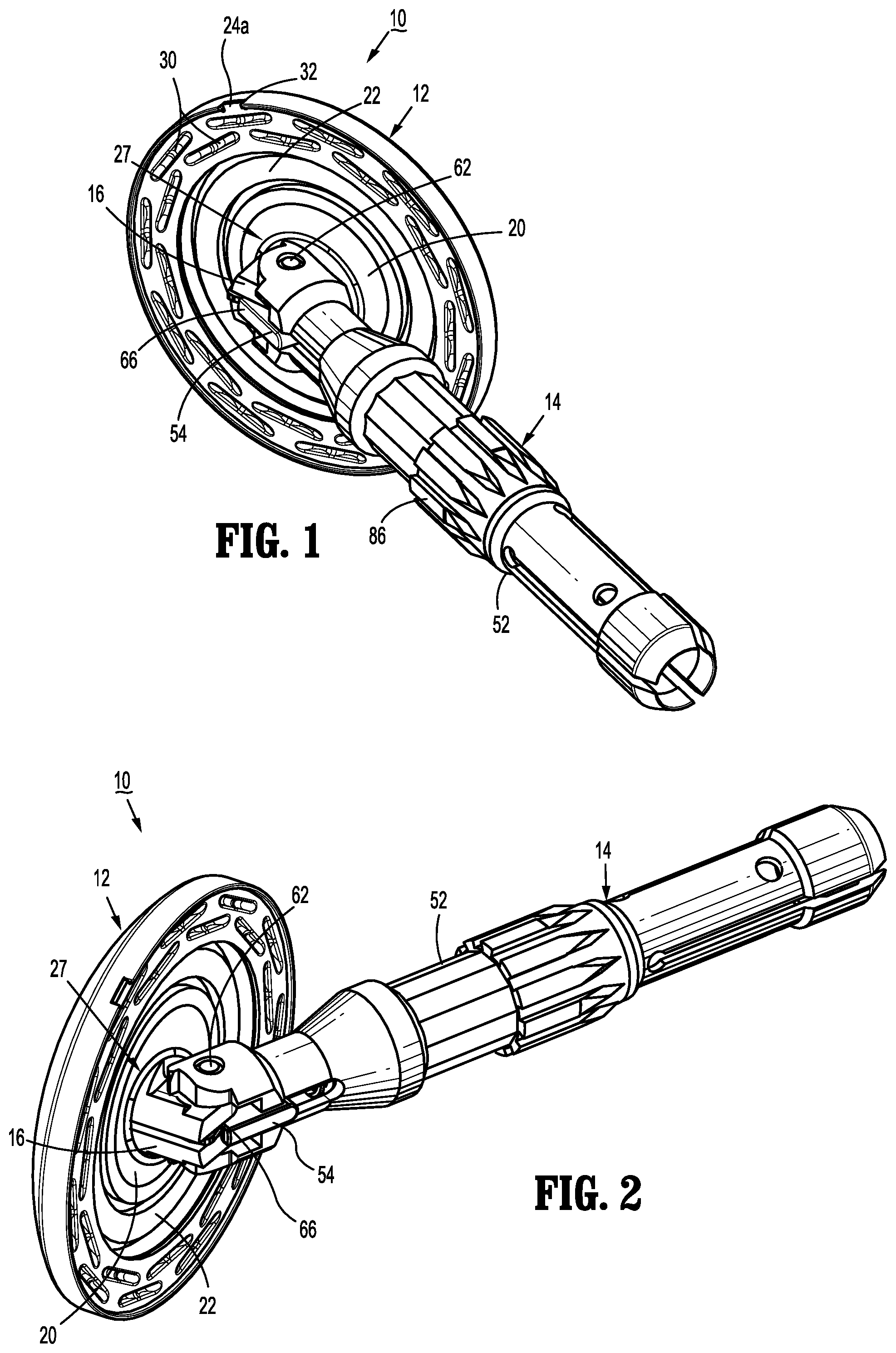
FIG. 1 is a side perspective view from one end of the presently disclosed anvil assembly with the anvil head tilted;
FIG. 2 is a side perspective view from the other end of the anvil assembly shown in FIG. 1;
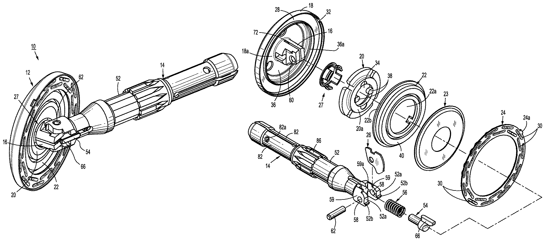
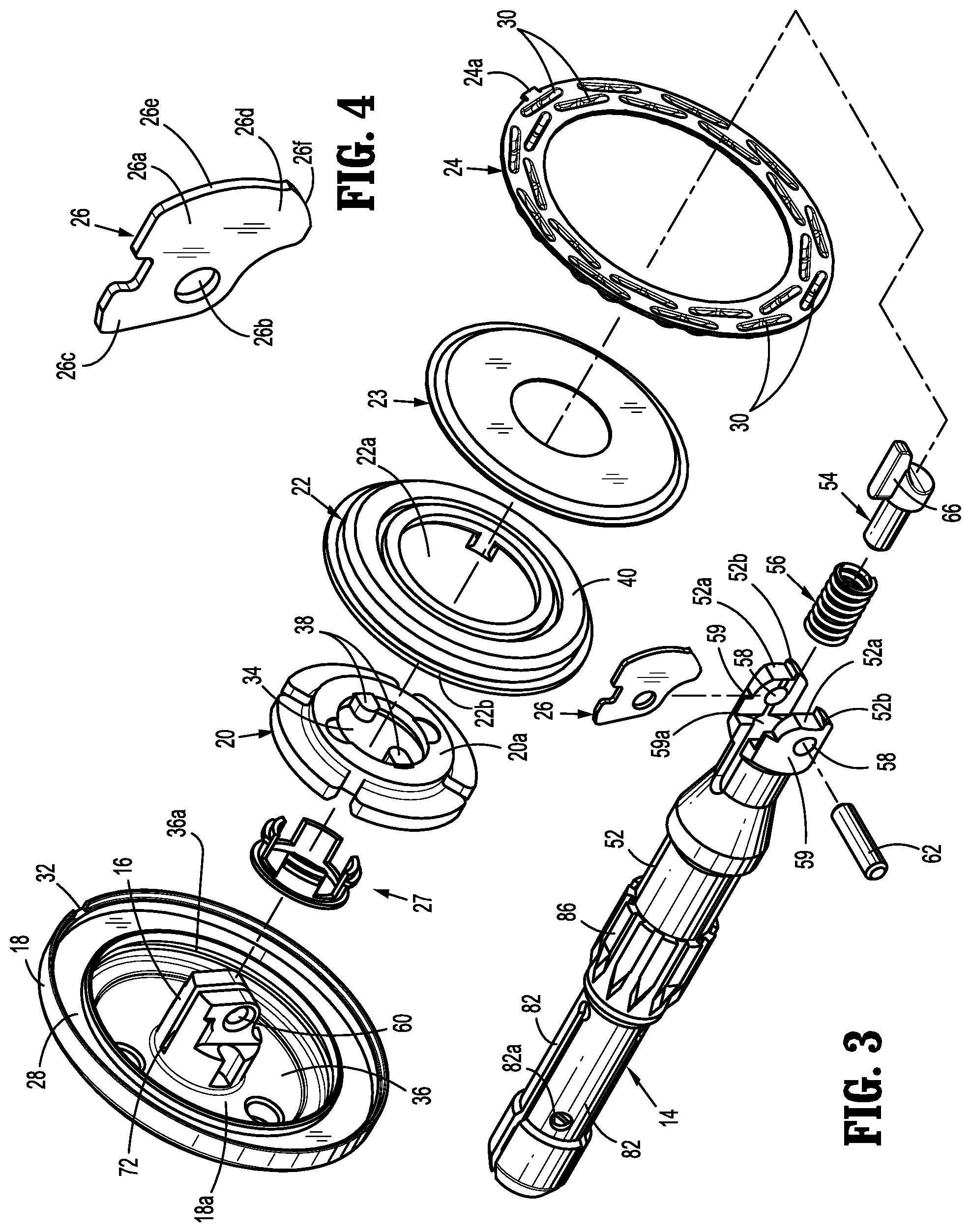
FIG. 3 is a side perspective view with parts separated of the anvil assembly shown in FIGS. 2 and 3;
FIG. 4 is a side perspective view of the cam latch member of the anvil assembly shown in FIGS. 1-3;
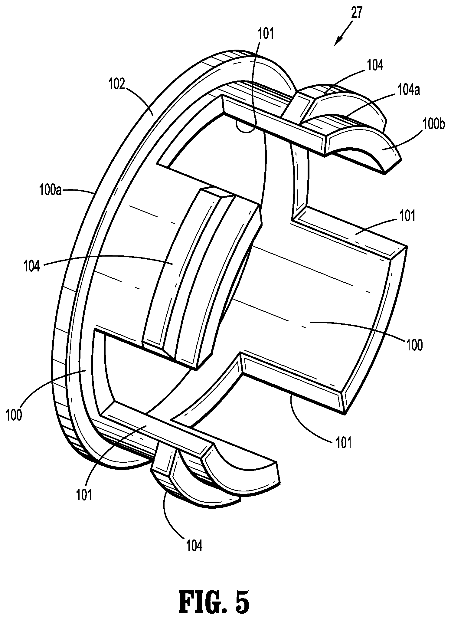
FIG. 5 is a side perspective view of the frangible retainer member of the anvil assembly shown in FIGS. 1-3;
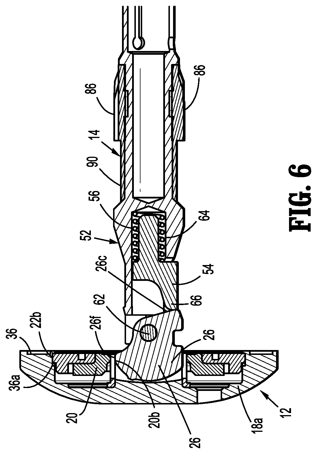
FIG. 6 is a side cross-sectional view of the anvil head and distal end of the center rod assembly taken through the cam latch member with the anvil head in the non-tilted or operative position;
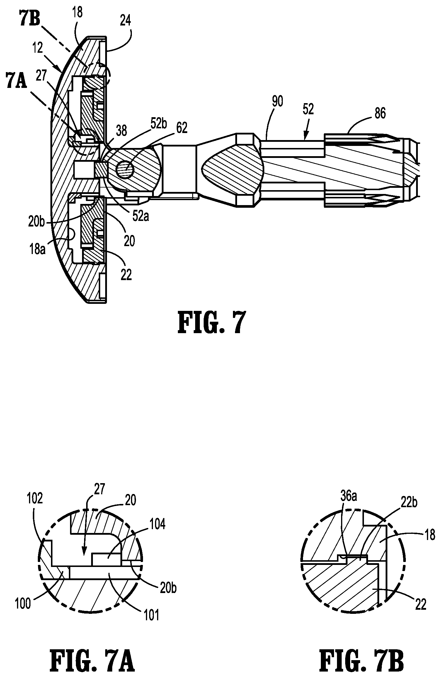
FIG. 7 is a side cross-sectional view of the anvil head and distal end of the center rod assembly with backup plate and cutting ring in their proximal position in the anvil head housing;
FIG. 7A is an enlarged view of indicated area 7A shown in FIG. 7;
FIG. 7B is an enlarged view of indicated area 7B shown in FIG. 7;
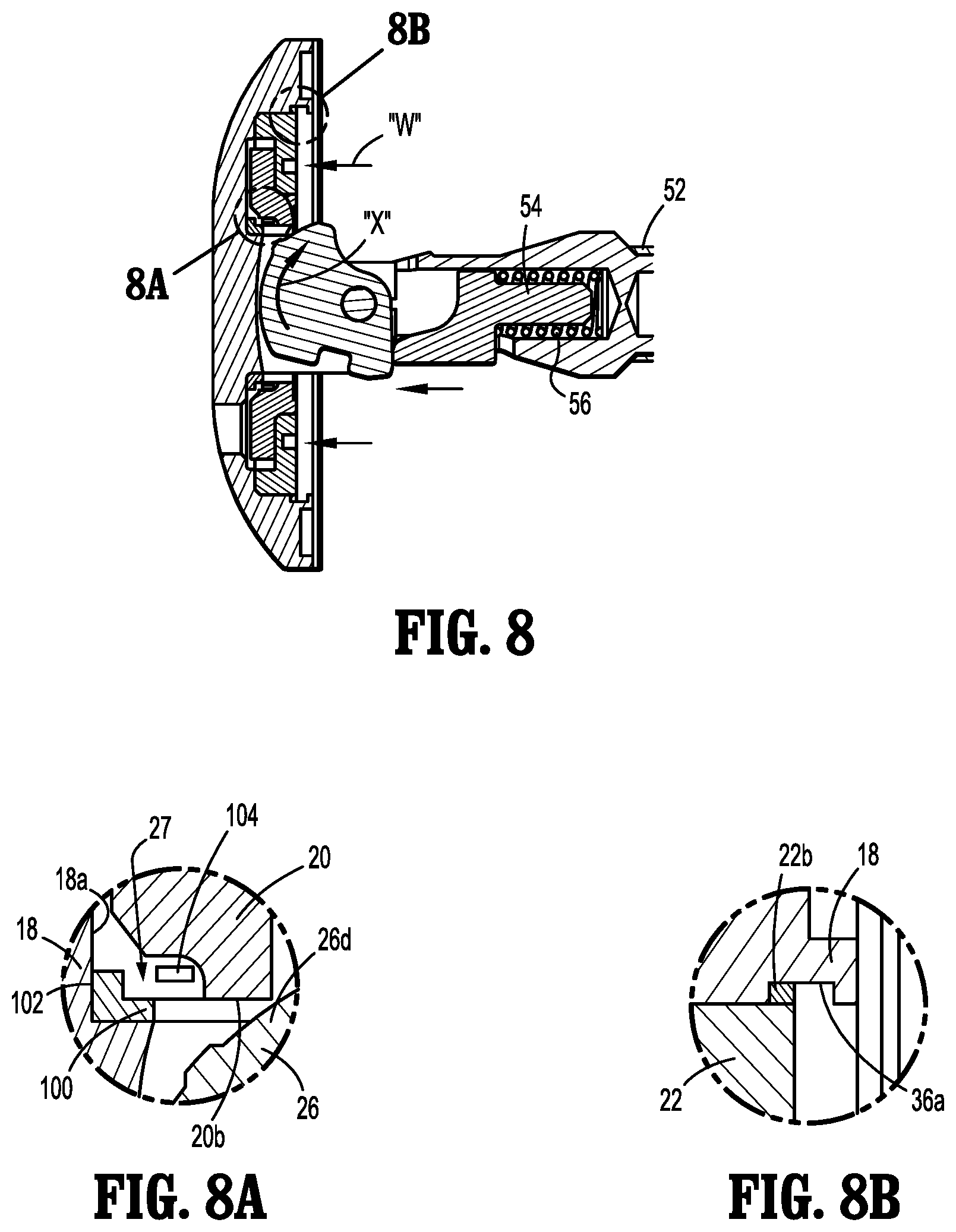
FIG. 8 is a side cross-sectional view of the anvil head and distal end of the center rod assembly taken through the cam latch member prior to tilting of the anvil head with the backup plate and cutting ring in their advanced or distal position in the anvil head housing;
FIG. 8A is an enlarged view of indicated area 8A shown in FIG. 8;
FIG. 8B is an enlarged view of indicated area 8B shown in FIG. 8; and
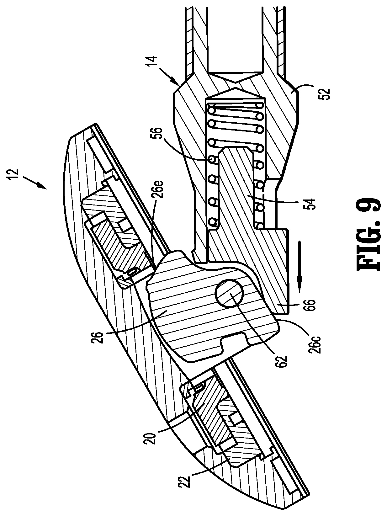
FIG. 9 is a side cross-sectional view of the anvil head and distal end of the anvil center rod assembly with the backup plate and cutting ring in their advanced position in the anvil head housing and the anvil head in the tilted position.
DETAILED DESCRIPTION OF EMBODIMENTS
Embodiments of the presently disclosed anvil assembly will now be described in detail with reference to the drawings in which like reference numerals designate identical or corresponding elements in each of the several views. As is common in the art, the term "proximal" refers to that part or component closer to the user or operator, i.e. surgeon or clinician, while the term "distal" refers to that part or component further away from the user.
FIGS. 1-9 illustrate an anvil assembly 10 which is suitable for use with a surgical stapling device for performing, for example, circular anastomoses of hollow tissue organs and hemorrhoid surgeries. Referring to FIGS. 1-3, anvil assembly 10 includes a head assembly 12 and a center rod assembly 14. Head assembly 12 includes a post 16, a housing 18, a backup member or plate 20, a cutting ring 22, a cutting ring cover 23, an anvil plate 24, a cam latch member 26, and a frangible retaining member 27. As shown, post 16 is monolithically formed with and centrally positioned within head 18. Alternately, head 18 and post 16 may be formed separately and fastened together using a known fastening technique, e.g., adhesive, welding, friction fit, etc. Anvil plate 24 is supported in an outer annular recess 28 (FIG. 3) of housing 18 and includes a plurality of staple deforming pockets 30 for receiving and deforming staples. At least one tab 24a extends radially outwardly from anvil plate 24 and is received within a cutout 32 formed in an outer rim of housing 18. Tab 24a and cutout 32 function to align or properly position anvil plate 24 within annular recess 28 of housing 18.
With particular reference now to FIG. 3, backup plate 20 includes a central opening 34 which allows backup plate 20 to be positioned about post 16. Backup plate 20 is configured to be received within an inner annular recess 36 of housing 18 formed between post 16 and outer annular recess 28. Backup plate 20 includes a raised platform 20a. Although platform 20a is illustrated as having a circular shape, other configurations are envisioned, e.g., square, rectangular, triangular, etc. Backup plate 20 includes a pair of inwardly extending fingers 38 which will be described in further detail below. Backup plate 20 is formed from a relatively hard material, e.g., a metal. Alternately other materials of construction may be used to construct backup plate 20.
Cutting ring 22 includes an opening 22a having a configuration substantially the same as platform 20a of backup plate 20. Cutting ring 22 includes an outer lip 22b configured to be received within an annular groove 36a formed in housing 18 (FIG. 6). As will be described in further detail below, outer lip 22b of cutting ring 22 is configured to maintain cutting ring 22 and backup plate 20 in a proximal position about post 16 and within inner annular recess 36 of housing 18 prior to a staple forming procedure. Cutting ring 22 may be formed from polyethylene or other suitable material. Cutting ring 22 is fixedly secured to backup plate 20 using, for example, an adhesive, to form a backup plate/cutting ring assembly. In one embodiment, cutting ring 22 is over-molded to backup plate 20 with undercuts. Alternatively, backup plate 20 and cutting ring 22 may be formed as a single or unitary structure.
With reference still to FIG. 3, cutting ring cover 23 is configured to be secured to an outwardly facing or proximal surface 40 of cutting ring 22 using, for example, an adhesive. In one embodiment, cutting ring cover 23 is formed from a material or materials which have a hardness greater than that of cutting ring 22, e.g., Mylar. In other embodiments, cutting ring cover 23 includes two layers of Mylar (not shown) which are joined together using an adhesive and/or a polypropylene coating. Alternately, cutting ring 22 need not have a cover.
Backup plate 20 and cutting ring 22 are configured to be movably mounted about post 16. As will be described in further detail below, backup plate 20 and cutting ring 22 are configured to move from an initial or proximal position (FIGS. 6 and 7) about post 16 and within inner annular recess 36 of housing 18 to an advanced or distal position (FIG. 8) about post 16 and within inner annular recess 36 of housing 18. As discussed in further detail below, in the proximal position, backup plate 20 prevents head assembly 12 from rotating relative to center rod assembly 14 and, in the distal position, backup plate 20 does not prevent head assembly 12 from rotating relative to center rod assembly 14.
With reference still to FIG. 1-3, center rod assembly 14 includes a center rod 52, a plunger 54, and plunger spring 56. A first end of center rod 52 includes a pair of arms 59 which define a cavity 59a (FIG. 3). Each arm 59 has a transverse throughbore 58 which is aligned with a central longitudinal axis of center rod 52. Alternately, throughbores 58 can be offset from the longitudinal axis of center rod 52. Post 16 of anvil head assembly 12 is dimensioned to be positioned within cavity 59a and also includes a transverse throughbore 60. A pivot member 62 pivotably secures post 16 to center rod 52 via throughbore 58 of each arm 59 and throughbore 60 of post 16 such that anvil head assembly 12 is pivotably mounted to center rod assembly 14. For a more detailed description of center rod assembly 14, please refer to the '581 publication, the content of which was previously incorporated herein by reference.
With reference now to FIGS. 3 and 4, cam latch member 26 includes a body 26a having a throughbore 26b. Throughbore 26b is dimensioned to receive pivot member 62 such that cam latch member 26 is pivotally mounted within a transverse slot 72 (FIG. 3) of post 16 about pivot member 62. Cam latch member 26 includes a first body portion 26c which is configured to extend partially from slot 72 of post 16 and be positioned for engagement by finger 66 of plunger 54. Cam latch member 26 also includes an edge 26f which is configured to be urged into engagement with an inner periphery of backup plate 20 by finger 66 of plunger 54 when anvil head 12 is in its non-tilted or operative position (FIG. 6).
With reference now to FIG. 5, frangible retainer member 27 has a first end 100a and a second end 100b and includes a substantially annular body portion 100 having a retaining ring or portion 102 formed near first end 100a and a frangible ring or portion 104 spaced from retaining portion 102 and formed adjacent second end 100b. Retaining ring 102 is configured to secure frangible retainer member 27 about post 16 of head assembly 12. As will be discussed in further detail below, frangible ring 104 is configured to selectively maintain backup plate 20 and cutting ring 22 in the proximal position (FIGS. 6 and 7). Frangible ring 104 may include a stress riser or groove 104a, perforations, or another weakened portion or portions disposed between frangible ring 104 and annular body portion 100 to aid in separation of frangible ring 104 from annular member 100. Frangible retainer member 27 defines a plurality of cutouts 101 configured to accommodate fingers 38 (FIG. 7) of backup plate 20 and cam latch member 26 (FIG. 6).
When frangible retainer member 27 is positioned about post 16, retaining ring 102 is positioned adjacent a back wall 18a of housing 18. Frangible ring 104 is positioned between backup plate 20 and housing 18. Frangible ring 104 is configured to maintain backup plate 20 and cutting ring 22 in the proximal position (FIGS. 6 and 7) until a predetermined force sufficient to fracture or separate frangible ring 104 from annular body portion 100 is applied to the backup plate/cutting ring assembly. The predetermined force can be close to but is less than the force applied by an annular cutting blade (not shown) of a surgical stapling device (not shown) to backup plate 20 (FIG. 3) when the knife blade engages the backup plate/cutting ring assembly. In one embodiment, the predetermined force is between about ten pounds and about ninety pounds. In another embodiment, the predetermined force is about thirty (30) pounds. When the predetermined force is reached, e.g., during cutting of tissue, frangible ring 104 fractures or separates from annular body 100, thereby allowing backup plate 20 to be pushed distally within inner annular recess 36 of housing 18. In any of the embodiments disclosed herein, frangible retainer member 27 may have a continuous ring without cutouts 101 so that the parts stay together. The four sections formed by cutouts 101 could become jammed, preventing the anvil from tilting.
Referring to FIGS. 6 and 7, anvil assembly 10 is shown in a pre-fired, operative position. In the pre-fired, operative position, backup plate 20 is spaced from back wall 18a of housing 18 and fingers 38 (FIG. 7) of backup plate 20 engage protrusions 52b formed adjacent top surface 52a of center rod 52 to prevent tilting of anvil head assembly 12 about pivot member 62. As shown in FIG. 6, finger 66 of plunger 54 is urged by spring 56 into engagement with body portion 26c of cam latch member 26 to urge cam latch member 26 in a clockwise direction about pivot member 62 such that edge 26f of cam latch member 26 engages an inner periphery 20b of backup member 20. Frangible retainer member 27 prevents inadvertent or premature movement of backup plate 20 distally within inner annular recess 36 of housing 18 to prevent premature or inadvertent tilting of anvil head assembly 12. Specifically, and with particular reference to FIG. 7A, backup plate 20 engages frangible ring 104 of frangible retaining member 27, thereby maintaining backup plate 20 in the proximal position. With particular reference to FIG. 7B, backup plate 20 is further maintained in the proximal position within inner annular recess 36 of housing 18 through receipt of lip 22b of cutting ring 22 within annular groove 36a of housing 18.
During a stapling procedure, anvil assembly 10 is attached to a surgical stapling device (not shown) and the surgical stapling device is fired in the manner described in the '060 patent, the content of which was previously incorporated herein by reference. With reference now to FIG. 8, during firing of the surgical stapling device, a knife blade (not shown) of the surgical stapling device engages cutting ring 22 (or cutting ring cover 23) and applies a distal force on the backup plate/cutting ring assembly 20/22. As described above, when a predetermined force is applied to the backup plate/cutting ring assembly, the force is transferred through the backup plate/cutting ring assembly 20/22 to frangible ring 104 of frangible retaining member 27. Upon application of the predetermined force to frangible ring 104, frangible ring 104 separates from annular body portion 100 of frangible retaining member 27 to allow the backup plate/cutting ring assembly 20/22 to be pushed distally, in the direction indicated by arrow "W", into inner annular recess 36 of housing 18. The distal movement of the backup plate/cutting ring assembly 20/22 causes fingers 38 (FIG. 7) of backup plate 20 to move away from and out of engagement with protrusions 52b (FIG. 7) of center rod 52. As inner periphery 20b of backup plate 20 moves past edge 26f of cam latch member 26, cam latch member 26 is pivoted, in the direction indicated by arrow "X" in FIG. 8, by plunger 54 to a position in which body portion 26d is positioned in front of and engages backup plate 20 (FIG. 8A). Engagement of plunger 54 with cam latch member 26 and subsequently with post 16 urges anvil head assembly 12 towards the tilted position.
With particular reference to FIG. 8A, during distal movement of backup plate/cutting ring assembly 20/22, frangible ring 104 of frangible retaining member 27 is separated from annular body portion 100 of frangible retaining member 27 and moved distally. Separate frangible ring 104 remains trapped between back wall 18a of housing 18 and backup plate/cutting ring assembly 20/22.
With particular reference now to FIG. 8B, in addition to separation of frangible ring 104 from annular body 100, distal movement of backup plate/cutting ring assembly 20/22 causes lip 22b formed on cutting ring 22 to be sheared off from the body portion of cutting ring 22. Lip 22b remains within groove 36a of housing 18. Alternatively, the knife blade (not shown) of the surgical stapling device (not shown) may cut through cutting ring 22, thereby separating the portion of cutting ring 22 that includes lip 22b from the remainder of cutting ring 22. The portion of cutting ring 22 that includes lip 22b remains within groove 36a of housing 18.
It is noted that anvil head assembly 12 will not immediately tilt upon firing of a surgical stapling device (not shown) because, upon firing, anvil head assembly 12 is in an approximated position, i.e., the anvil head assembly 12 is in close alignment with the shell assembly of the stapling device (not shown). As such, the tilting of anvil head assembly 12 is prevented by engagement with the shell assembly (not shown) of the surgical stapling device (not shown) until anvil head assembly 12 is unapproximated.
Referring to FIG. 9, as anvil head assembly 12 pivots towards its tilted position, finger 66 of plunger 54 maintains surface 26e of cam latch member 26 in contact with backup plate 20 to prevent backup plate 20 from sticking to the knife blade (not shown) of the surgical stapling device as the knife blade is retracted. It is noted that curved surface 26e of cam latch member 26 is configured to eliminate any gap and ensure contact between surface 26e of cam latch member 26 and backup plate 20 to hold backup plate 20 in place during and after the knife blade is retracted such that backup plate/cutting ring assembly 20/22 stays in the distal position during tilting of anvil assembly 12.
It will be understood that various modifications may be made to the embodiments disclosed herein. For example, although shown having an annular configuration, the frangible retaining member may have other configurations, e.g., square, oval, rectangular, etc. Therefore, the above description should not be construed as limiting, but merely as exemplifications of preferred embodiments. Those skilled in the art will envision other modifications within the scope and spirit of the claims appended hereto.
* * * * *
D00000
D00001
D00002
D00003
D00004
D00005
D00006
D00007
XML
uspto.report is an independent third-party trademark research tool that is not affiliated, endorsed, or sponsored by the United States Patent and Trademark Office (USPTO) or any other governmental organization. The information provided by uspto.report is based on publicly available data at the time of writing and is intended for informational purposes only.
While we strive to provide accurate and up-to-date information, we do not guarantee the accuracy, completeness, reliability, or suitability of the information displayed on this site. The use of this site is at your own risk. Any reliance you place on such information is therefore strictly at your own risk.
All official trademark data, including owner information, should be verified by visiting the official USPTO website at www.uspto.gov. This site is not intended to replace professional legal advice and should not be used as a substitute for consulting with a legal professional who is knowledgeable about trademark law.