Processing 3D medical images to enhance visualization
Douglas
U.S. patent number 10,586,400 [Application Number 15/904,092] was granted by the patent office on 2020-03-10 for processing 3d medical images to enhance visualization. The grantee listed for this patent is Robert E Douglas. Invention is credited to Robert E Douglas.


| United States Patent | 10,586,400 |
| Douglas | March 10, 2020 |
Processing 3D medical images to enhance visualization
Abstract
A 3D image processing system includes voxel adjustments based on radiodensity, filtering and segmentation, each of which may be selected, configured, and applied in response to controller-entered commands. Voxel adjustments based on radiodensity may include changes to grayscale values and color, e.g. to enhance selected tissues or to emphasize differences between tissues of similar radiodensity. Voxel adjustments based on radiodensity may include demarcation, and changes to voxel size, shape, and orientation. Filtering may include removing a portion of voxels of a selected radiodensity from a presented image. Segmentation may characterize voxels based on nearest neighbors, and grow features or fill gaps. Multiple images may be generated with different configuration settings and be combined into a composite image.
| Inventors: | Douglas; Robert E (Winter Park, FL) | ||||||||||
|---|---|---|---|---|---|---|---|---|---|---|---|
| Applicant: |
|
||||||||||
| Family ID: | 67685229 | ||||||||||
| Appl. No.: | 15/904,092 | ||||||||||
| Filed: | February 23, 2018 |
Prior Publication Data
| Document Identifier | Publication Date | |
|---|---|---|
| US 20190266805 A1 | Aug 29, 2019 | |
| Current U.S. Class: | 1/1 |
| Current CPC Class: | G06T 15/08 (20130101); G06T 5/00 (20130101); G06T 19/20 (20130101); G06T 7/10 (20170101); G06T 2219/2016 (20130101); G06T 2219/2012 (20130101); G06T 2219/2021 (20130101) |
| Current International Class: | G06T 19/20 (20110101); G06T 15/08 (20110101) |
References Cited [Referenced By]
U.S. Patent Documents
| 6765570 | July 2004 | Cheung |
| 8819591 | August 2014 | Wang |
| 9715761 | July 2017 | Lee |
| 9990712 | June 2018 | Gazit |
| 2011/0158494 | June 2011 | Bar-Shalev |
| 2012/0232375 | September 2012 | Zebaze |
| 2013/0004043 | January 2013 | Ross |
| 2013/0188848 | July 2013 | Helm |
| 2013/0230224 | September 2013 | Claude |
| 2015/0138201 | May 2015 | Brown |
| 2015/0170401 | June 2015 | Major |
| 2015/0287188 | October 2015 | Gazit |
| 2015/0348259 | December 2015 | Souza |
| 2016/0163048 | June 2016 | Yee |
| 2016/0300351 | October 2016 | Gazit |
| 2016/0345925 | December 2016 | Westerhoff |
| 2018/0329609 | November 2018 | De Swarte |
| 2018/0365829 | December 2018 | Madabhushi |
| 2019/0057555 | February 2019 | Gallop |
Other References
|
"Segmentation and Separation of Cerebral Aneurysms: A Multi-Phase Approach", by Alireza Nikravanshalmani, Mojdeh Karamimohammdi, & Jamshid Dehmeshki, 8th International Symposium on Image and Signal Processing Analysis, pp. 505-510, Sep. 4-6, 2013. (Year: 2013). cited by examiner . "Visualizing Inner Structures in Multimodal Volume Data", by Isabel H. Manssour, Sergio S. Furuie, Silvia D. Olabarriaga, & Carla M.D.S. Freitas, Proceedings of the XV Brazilian Symposium on Computer Graphics and Image Processing, pp. 51-58, Jan. 2002. (Year: 2002). cited by examiner . "3D Voxel Fusion of Multi-modality Medical Images in a Clinical Treatment Planning System", by Huchen Xie, Guang Li, Holly Ning, Cynthia Menard, C. Norman Coleman, & Robert W. Miller, Proceedings of the 17th IEEE Symposium on Computer-Based Medical Systems, pp. 48-53, Jan. 2004. (Year: 2004). cited by examiner . "Real-Time Volume Rendering Visualization of Dual-Modality PET/CT Images With Interactive Fuzzy Thresholding Segmentation", by Jinman Kim, Weidong Cai, Stefan Eberl, & Dagan Feng, IEEE Transactions on Information Technology in Biomedicine, vol. 11, No. 2, pp. 161-169, Mar. 2007. (Year: 2007). cited by examiner . Kumar et al. "Automatic Colour Transfer Function Generation and 3D Reconstruction of DICOM images" Proceedings of CCSO, 2013. cited by applicant. |
Primary Examiner: Thompson; James A
Attorney, Agent or Firm: Anderson Gorecki LLP
Claims
What is claimed is:
1. An apparatus comprising: a controller; and an image processing system that generates a three-dimensional image comprising 3D pixel element type voxels corresponding to image data of a scanned volume, the image data comprising radiodensity values, the image processing system comprising visual representation adjustment logic that adjusts selected ones of the voxels based on selected ones of the radiodensity values, wherein the visual representation adjustment logic is configured in response to commands provided via the controller, the visual representation adjustment logic comprising: performing segmentation of an anatomic structure; performing grouping logic within said segmented anatomic structure that groups the selected ones of the voxels into a first range of radiodensity values; and performing visual representation adjustment logic that adjusts visual representation of the voxels of the first range of radiodensity values independently from a second range of radiodensity values.
2. The apparatus of claim 1 further comprising segmentation logic that performs segmentation, wherein the segmentation logic is configured in response to commands provided via the controller.
3. The apparatus of claim 2 wherein the segmentation logic classifies a voxel under consideration based on the tissue type of nearest neighbor voxels in a matrix.
4. The apparatus of claim 2 wherein the segmentation logic fills a gap in a structure.
5. The apparatus of claim 1 further comprising filtering logic that performs filtering, wherein the filtering logic is configured in response to commands provided via the controller.
6. The apparatus of claim 5 wherein the filtering logic removes some of the selected voxels from the three-dimensional image.
7. The apparatus of claim 6 wherein the filtering logic is temporally adjusted to present versions of an image corresponding to different filter configuration settings.
8. The apparatus of claim 1 wherein the visual representation adjustment logic changes a grayscale value of the selected voxels.
9. The apparatus of claim 1 wherein the visual representation adjustment logic changes a color value of the selected voxels.
10. The apparatus of claim 1 wherein the visual representation adjustment logic increases dynamic range of the selected voxels.
11. The apparatus of claim 1 wherein the visual representation adjustment logic changes size of the selected voxels.
12. The apparatus of claim 1 wherein the visual representation adjustment logic changes shape of the selected voxels.
13. The apparatus of claim 1 wherein the visual representation adjustment logic changes orientation of the selected voxels.
14. The apparatus of claim 1 wherein the visual representation adjustment logic demarks the selected voxels with color.
15. The apparatus of claim 1 wherein the visual representation adjustment logic is temporally adjusted to present versions of an image corresponding to different configuration settings.
16. The apparatus of claim 1 wherein the image processing system generates multiple images from the image data using different configuration settings, and combines the multiple images to generate the three-dimensional image as a composite image.
17. A method comprising: in an image processing system, generating a three-dimensional image comprising 3D pixel element type voxels corresponding to image data of a scanned volume, the image data comprising radiodensity values, wherein generating the three-dimensional image comprises: configuring visual representation adjustment logic with configuration settings in response to commands provided via a controller; and adjusting selected ones of the voxels based on selected ones of the radiodensity values in accordance with the configuration settings, comprising the steps of: performing segmentation of an anatomic structure; performing grouping logic within said segmented anatomic structure that groups the selected ones of the voxels into a first range of radiodensity values; and performing visual representation adjustment logic that adjusts visual representation of the voxels of the first range of radiodensity values independently from a second range of radiodensity values.
18. The method of claim 17 further comprising configuring segmentation logic in response to commands provided via the controller, and performing segmentation.
19. The method of claim 18 comprising the segmentation logic classifying a voxel under consideration based on the tissue type of nearest neighbor voxels in a matrix.
20. The method of claim 18 comprising the segmentation logic filling a gap in a structure.
21. The method of claim 17 further comprising configuring filtering logic in response to commands provided via the controller, and performing filtering.
22. The method of claim 21 comprising the filtering logic removing some of the selected voxels from the three-dimensional image.
23. The method of claim 22 comprising temporally adjusting the filtering logic to present versions of an image corresponding to different filter configuration settings.
24. The method of claim 17 wherein adjusting selected ones of the voxels comprises changing a grayscale value of the selected voxels.
25. The method of claim 17 wherein adjusting selected ones of the voxels comprises changing a color value of the selected voxels.
26. The method of claim 17 wherein adjusting selected ones of the voxels comprises increasing dynamic range of the selected voxels.
27. The method of claim 17 wherein adjusting selected ones of the voxels comprises changing size of the selected voxels.
28. The method of claim 17 wherein adjusting selected ones of the voxels comprises changing shape of the selected voxels.
29. The method of claim 17 wherein adjusting selected ones of the voxels comprises changing orientation of the selected voxels.
30. The method of claim 17 wherein adjusting selected ones of the voxels comprises demarking the selected voxels with color.
31. The method of claim 17 wherein adjusting selected ones of the voxels comprises temporally adjusting configuration values to present versions of an image corresponding to different configuration settings.
32. The method of claim 17 comprising the image processing system generating multiple images from the image data using different configuration settings, and combining the multiple images to generate the three-dimensional image as a composite image.
Description
TECHNICAL FIELD
Aspects of the present disclosure are generally related to processing three-dimensional image data.
BACKGROUND
Known techniques for 3D viewing of medical images are described in U.S. Pat. No. 9,349,183, Method and Apparatus for Three Dimensional Viewing of Images, issued to Douglas, U.S. Pat. No. 8,384,771, Method and Apparatus for Three Dimensional Viewing of Images, issued to Douglas, Douglas, D. B., Petricoin, E. F., Liotta L., Wilson, E. D3D augmented reality imaging system: proof of concept in mammography. Med Devices (Auckl), 2016; 9:277-83, Douglas, D. B., Boone, J. M., Petricoin, E., Liotta, L., Wilson, E. Augmented Reality Imaging System: 3D Viewing of a Breast Cancer. J Nat Sci. 2016; 2(9), and Douglas, D. B., Wilke, C. A., Gibson, J. D., Boone, J. M., Wintermark, M. Augmented Reality: Advances in Diagnostic Imaging. Multimodal Technologies and Interaction, 2017; 1(4):29.
SUMMARY
All examples, aspects and features mentioned in this document can be combined in any technically possible way.
In accordance with an aspect an apparatus comprises: a controller; and an image processing system that generates a three-dimensional image comprising voxels corresponding to image data of a scanned volume, the image data comprising radiodensity values, the image processing system comprising visual representation adjustment logic that adjusts selected ones of the voxels based on selected ones of the radiodensity values, wherein the visual representation adjustment logic is configured in response to commands provided via the controller. Some implementations further comprise segmentation logic that performs segmentation, wherein the segmentation logic is configured in response to commands provided via the controller. Some implementations further comprise filtering logic that performs filtering, wherein the filtering logic is configured in response to commands provided via the controller. In some implementations the visual representation adjustment logic changes a grayscale value of the selected voxels. In some implementations the visual representation adjustment logic changes a color value of the selected voxels. In some implementations the visual representation adjustment logic increases dynamic range of the selected voxels. In some implementations the visual representation adjustment logic changes size of the selected voxels. In some implementations the visual representation adjustment logic changes shape of the selected voxels. In some implementations the visual representation adjustment logic changes orientation of the selected voxels. In some implementations the visual representation adjustment logic demarks the selected voxels with color. In some implementations the visual representation adjustment logic is temporally adjusted to present versions of an image corresponding to different configuration settings. In some implementations the filtering logic removes some of the selected voxels from the three-dimensional image. In some implementations the filtering logic is temporally adjusted to present versions of an image corresponding to different filter configuration settings. In some implementations the segmentation logic classifies a voxel under consideration based on the tissue type of nearest neighbor voxels in a matrix. In some implementations the segmentation logic fills a gap in a structure. In some implementations the image processing system generates multiple images from the image data using different configuration settings, and combines the multiple images to generate the three-dimensional image as a composite image.
In accordance with an aspect, a method comprises: in an image processing system, generating a three-dimensional image comprising voxels corresponding to image data of a scanned volume, the image data comprising radiodensity values, wherein generating the three-dimensional image comprises: configuring visual representation adjustment logic with configuration settings in response to commands provided via a controller; and adjusting selected ones of the voxels based on selected ones of the radiodensity values in accordance with the configuration settings. Some implementations further comprise configuring segmentation logic in response to commands provided via the controller, and performing segmentation. Some implementations further comprise configuring filtering logic in response to commands provided via the controller, and performing filtering. In some implementations adjusting selected ones of the voxels comprises changing a grayscale value of the selected voxels. In some implementations adjusting selected ones of the voxels comprises changing a color value of the selected voxels. In some implementations adjusting selected ones of the voxels comprises increasing dynamic range of the selected voxels. In some implementations adjusting selected ones of the voxels comprises changing size of the selected voxels. In some implementations adjusting selected ones of the voxels comprises changing shape of the selected voxels. In some implementations adjusting selected ones of the voxels comprises changing orientation of the selected voxels. In some implementations adjusting selected ones of the voxels comprises demarking the selected voxels with color. In some implementations adjusting selected ones of the voxels comprises temporally adjusting configuration values to present versions of an image corresponding to different configuration settings. Some implementations comprise the filtering logic removing some of the selected voxels from the three-dimensional image. Some implementations comprise temporally adjusting the filtering logic to present versions of an image corresponding to different filter configuration settings. Some implementations comprise the segmentation logic classifying a voxel under consideration based on the tissue type of nearest neighbor voxels in a matrix. Some implementations comprise the segmentation logic filling a gap in a structure. Some implementations comprise the image processing system generating multiple images from the image data using different configuration settings, and combining the multiple images to generate the three-dimensional image as a composite image.
BRIEF DESCRIPTION OF THE FIGURES
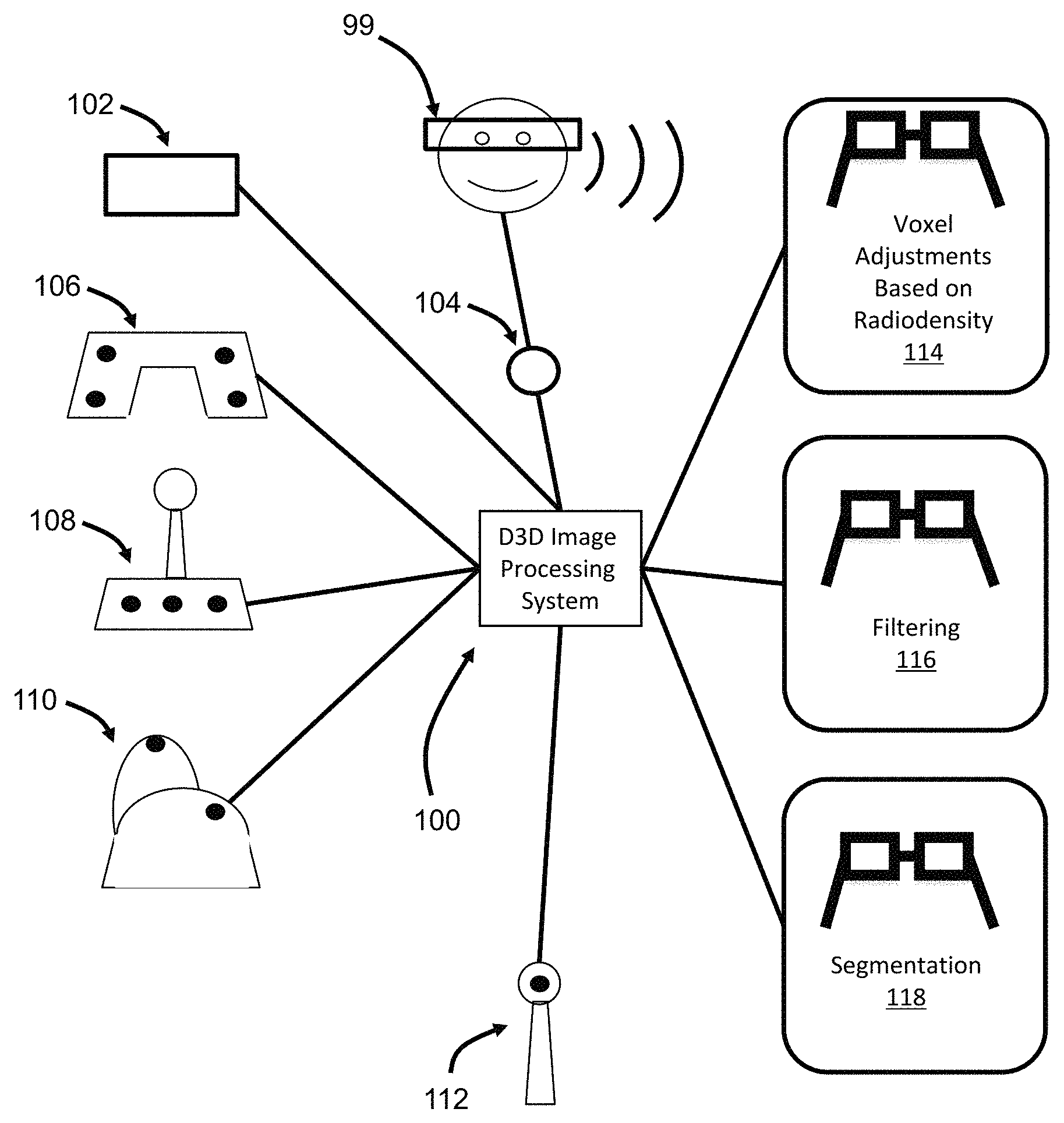
FIG. 1 illustrates a D3D image processing system.
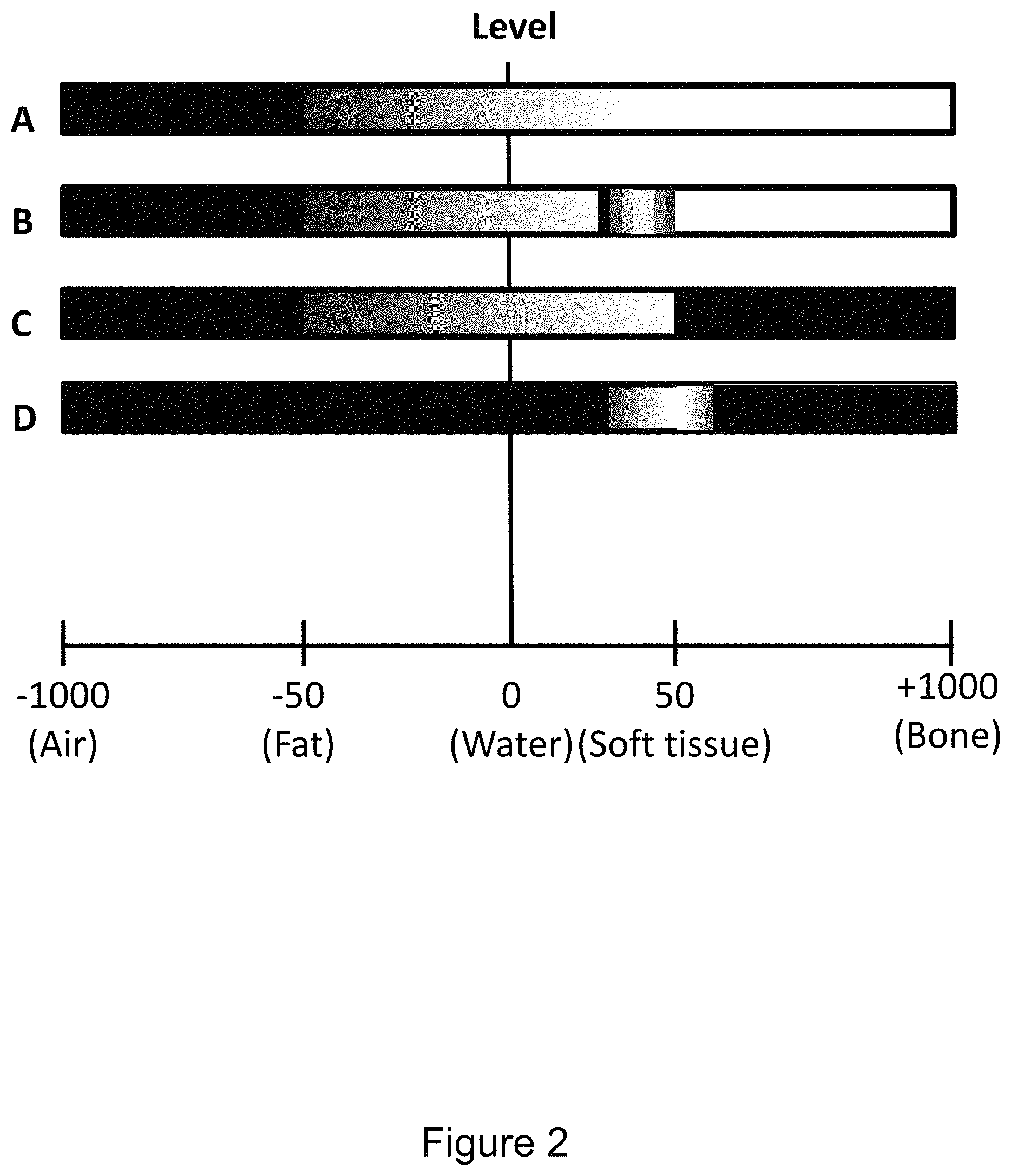
FIG. 2 illustrates aspects of voxel adjustments based on radiodensity in greater detail.
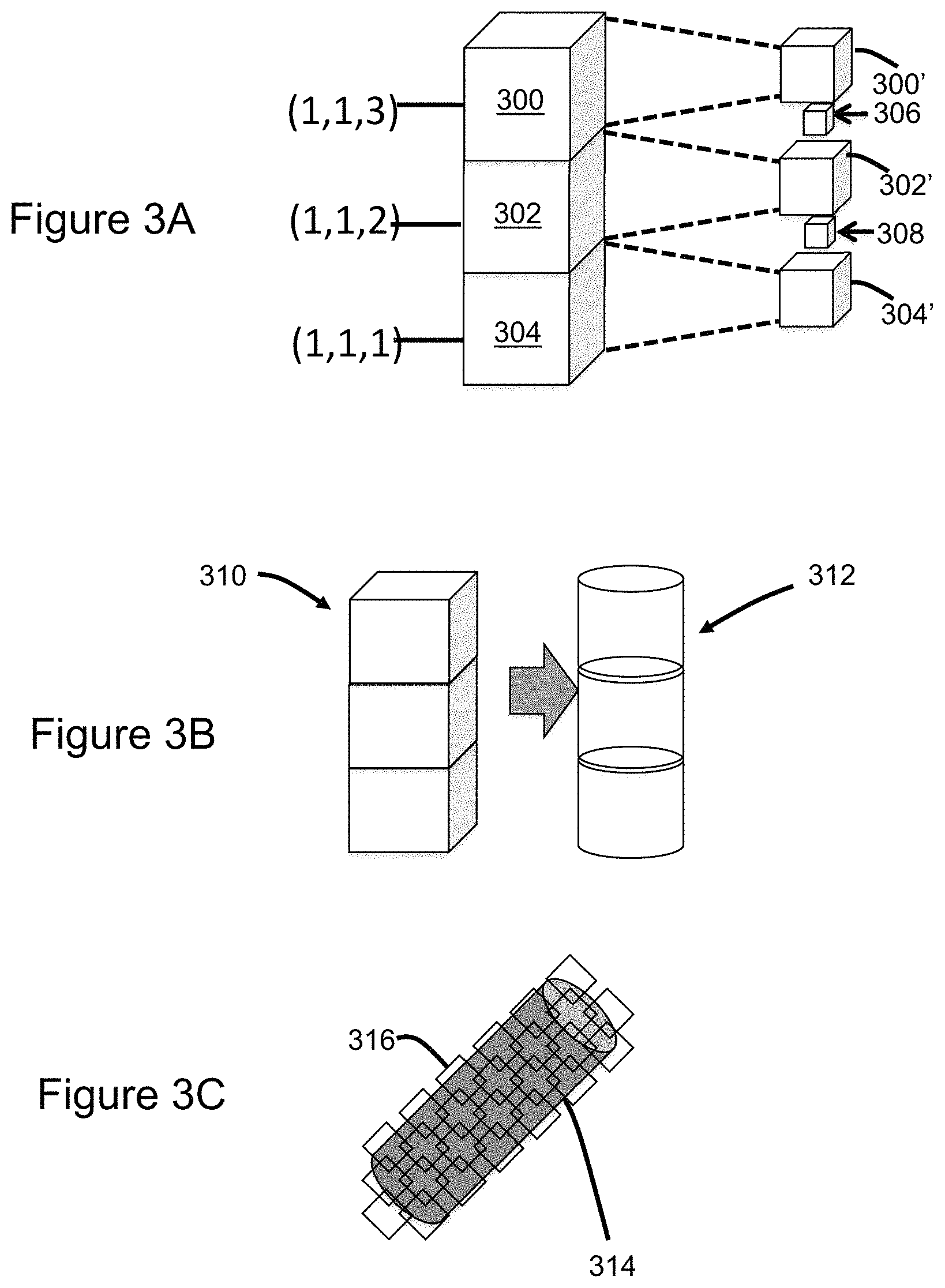
FIGS. 3A, 3B, and 3C illustrate adjustment of voxel size, shape, and orientation, respectively.
FIGS. 4A and 4B illustrate feature demarcation.
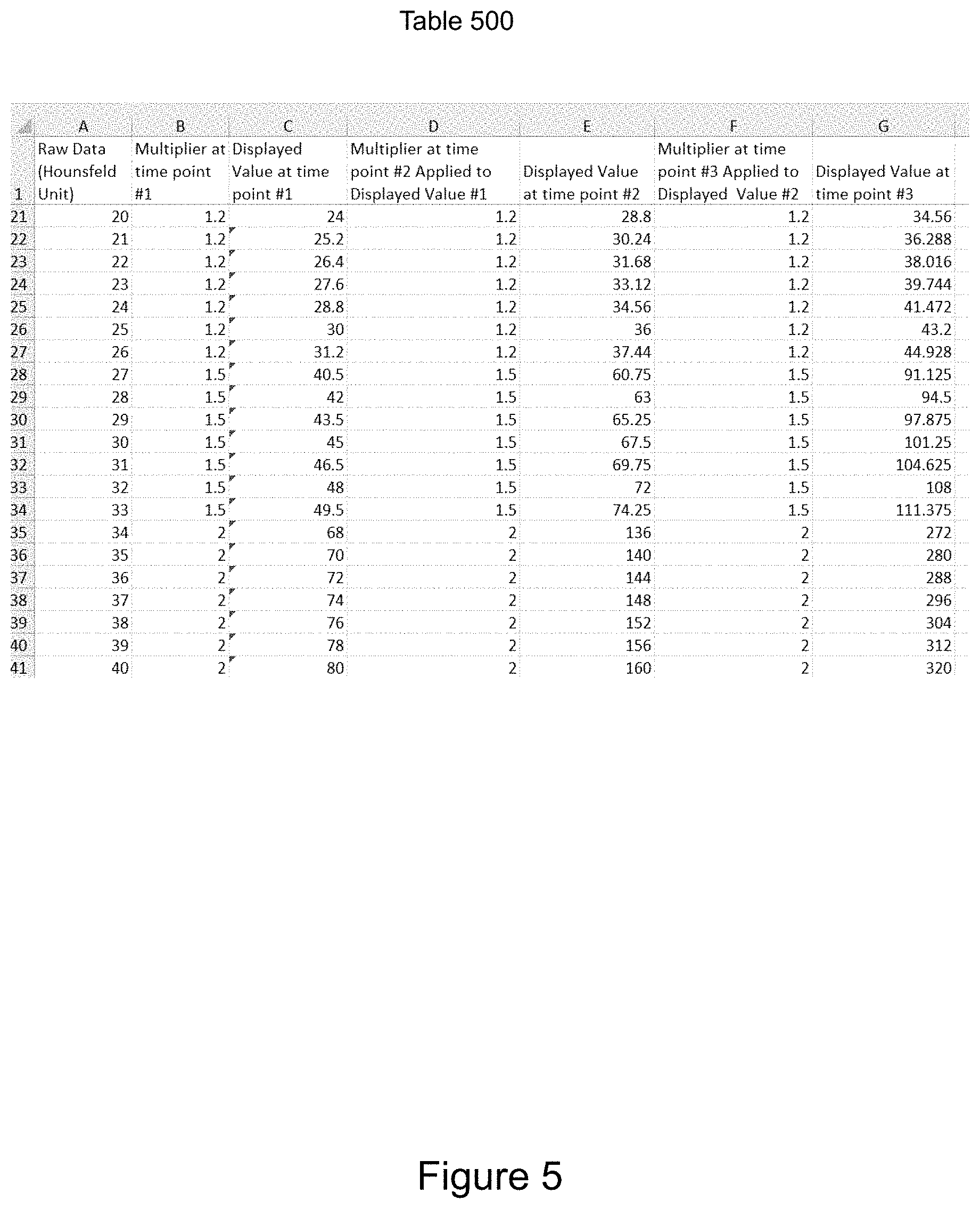
FIG. 5 illustrates mathematical adjustments of voxels to enhance discrimination between voxels based on grayscale values.
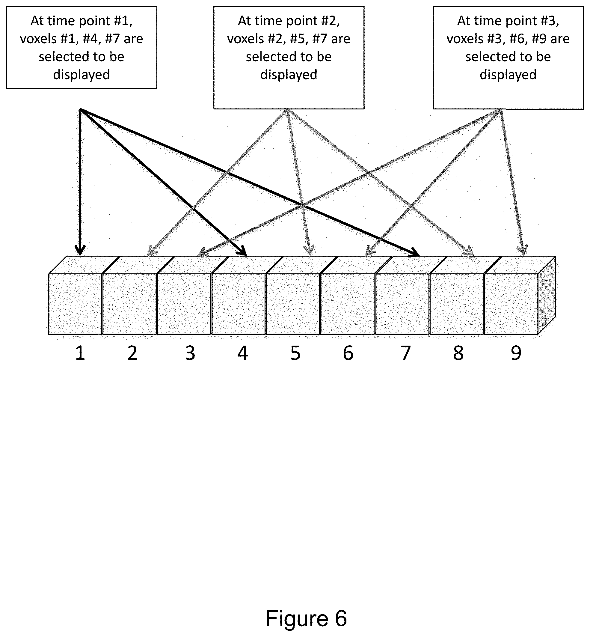
FIG. 6 illustrates aspects of filtering in greater detail.
FIG. 7 illustrates an aspect of segmentation in which a voxel is classified based on the type of tissue of its nearest neighbor voxels.
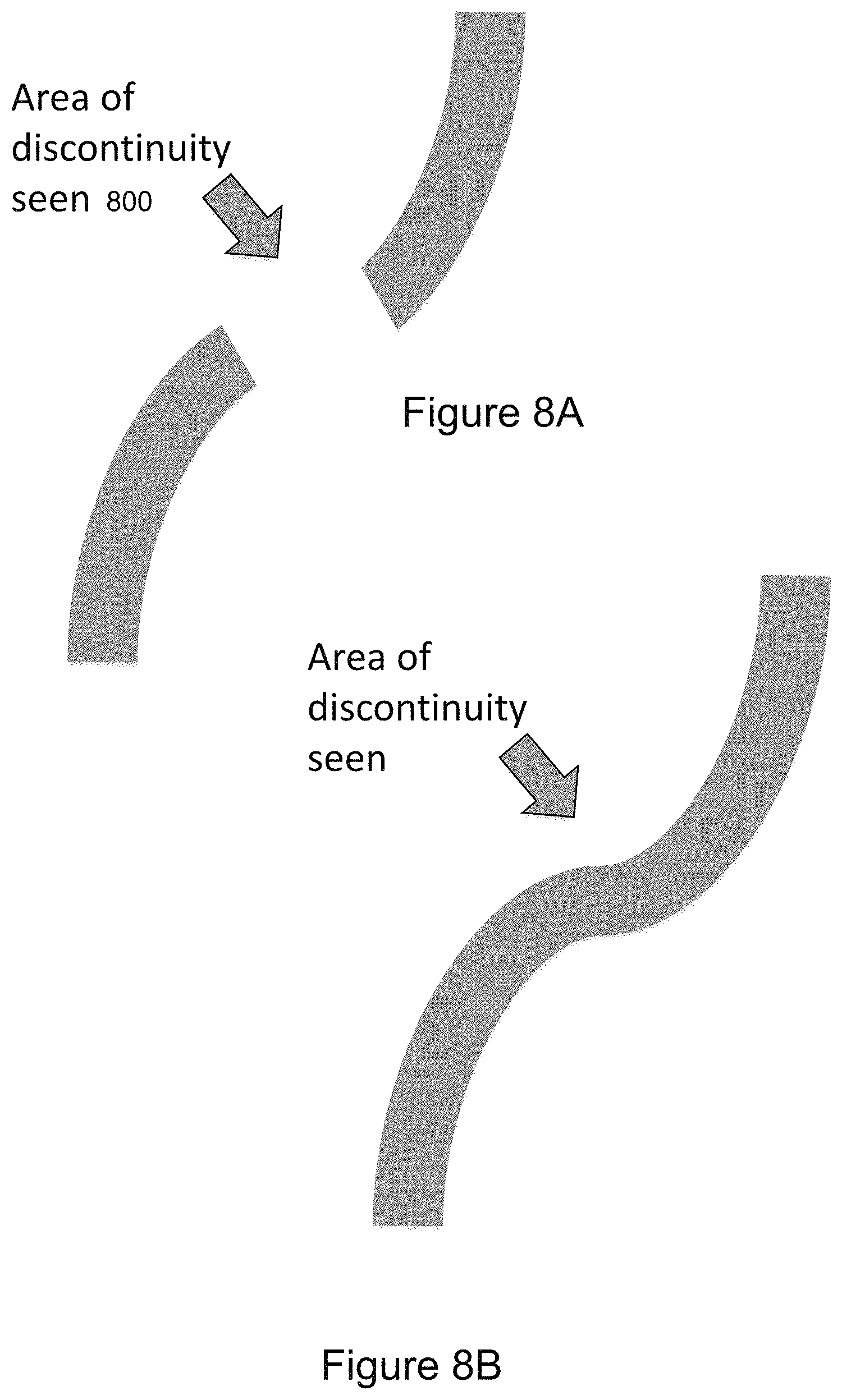
FIGS. 8A and 8B illustrate aspects of advanced segmentation wherein gaps in a vascular structure are filled.
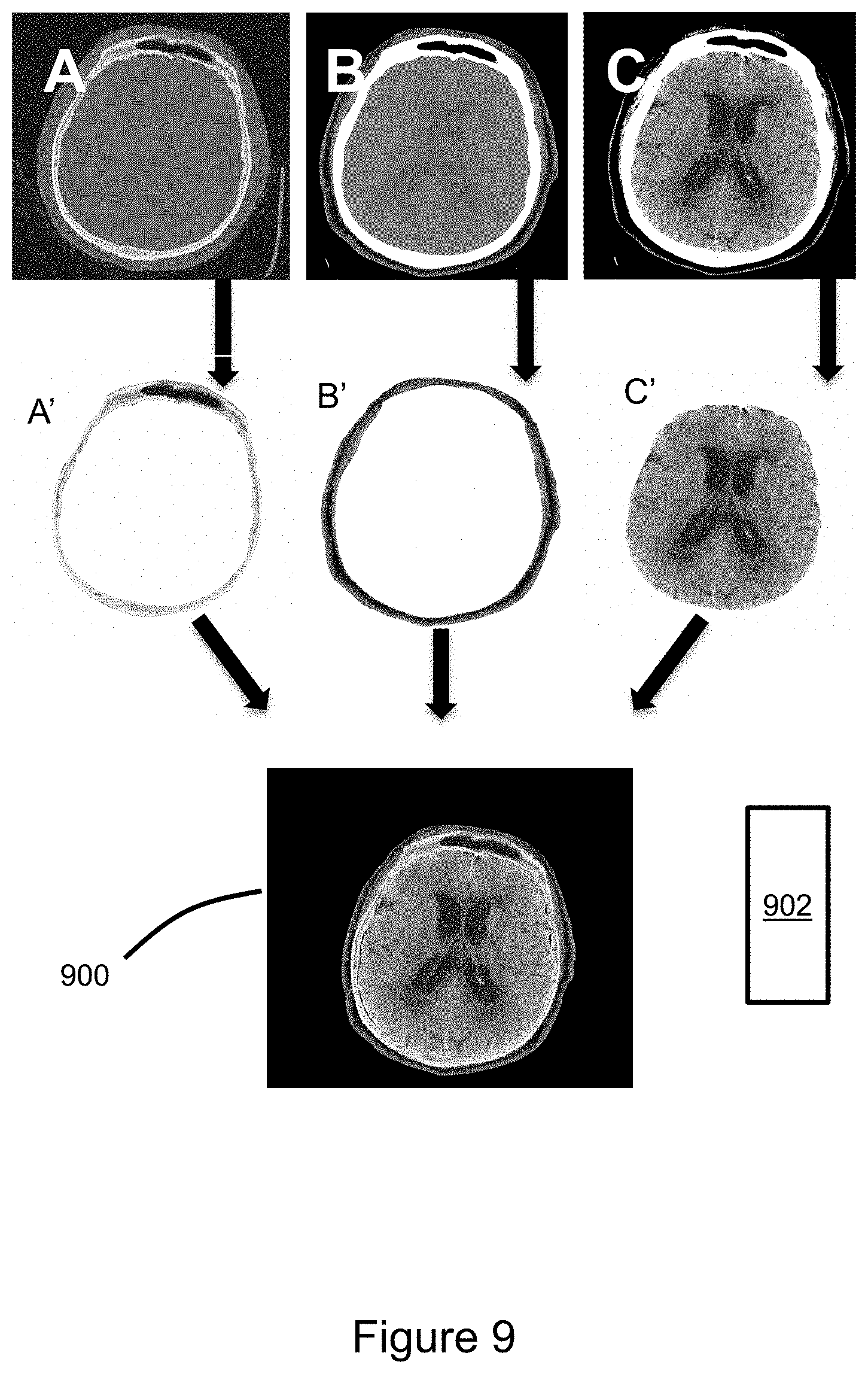
FIG. 9 illustrates use of controller-entered commands to process and combine three axial CT images of the head using the described image processing techniques.
FIG. 10 is a flow diagram of procedural steps in accordance with aspects of the invention.
DETAILED DESCRIPTION
Some aspects, features, and implementations described herein may include machines such as computers, electronic components, optical components, and processes such as computer-implemented steps. It will be apparent to those of ordinary skill in the art that the computer-implemented steps may be stored as computer-executable instructions on a non-transitory computer-readable medium. Furthermore, it will be understood by those of ordinary skill in the art that the computer-executable instructions may be executed on a variety of tangible processor devices. For ease of exposition, not every step, device or component that may be part of a computer or data storage system is described herein. Those of ordinary skill in the art will recognize such steps, devices and components in view of the teachings of the present disclosure and the knowledge generally available to those of ordinary skill in the art. The corresponding machines and processes are therefore enabled and within the scope of the disclosure.
In a D3D imaging system, a radiologist uses a controller to manipulate 3D (three-dimensional) images that may be viewed via special glasses or a VR (virtual reality) headset. The 3D images may be generated from radiological scan data, for example and without limitation from X-ray radiography, CT (computed tomography), PET (positron emission tomography), or Mill (magnetic resonance imaging). There will normally be a linear relationship between density or radiodensity values from the scan data and the grayscale values assigned to corresponding voxels of the 3D images. Advantages of existing examples may include improved depth perception and an improved human machine interface. Still, there are several challenges faced with this approach. First, an area of interest (e.g. tumor) may be in close proximity to structures that are similar in composition/density. Isolating the area of interest for better examination may be difficult. Second, many soft tissues in the body are mobile and deformable, so it can be difficult to achieve the best orientation to properly compare the tumor at multiple time points. Efficiently aligning the orientation to do so may be difficult. Third, certain portions of a tumor can respond to treatment and decrease in size while other portions of a tumor demonstrate increases in size. The pattern of tumor shrinkage has important prognostic implications. Furthermore, composition and complex morphologic features including speculations (spikes extending from the surface), irregular margins and enhancement also have important implications. Consequently, there is a need for a system that facilitates recognition of the subtle, yet important changes in size, shape and margins. Fourth, a patient with metastatic cancer has several areas of interest in different areas of the body. It is difficult and time consuming to find each of the areas of interest at every time point to determine interval change. Consequently, there is a need for a system that enables the observer to do this efficiently.
FIG. 1 illustrates an improved D3D image processing system 100 and various types of controllers and a VR headset 99 that interface with the D3D image processing system. A wide variety of controllers may be utilized, possibly including but not limited to one or more of a keyboard 102, microphone 104 (for voice control), hand held game-type controller 106, joy stick 108, high-end mouse 110, and wand 112. The controllers are used to enter commands that control an application that processes 3D image data and displays that 3D image data. As will be explained in greater detail below, the controllers are used to select, configure and implement image processing techniques including: voxel adjustments based on radiodensity 114; filtering 116; and segmentation 118.
Referring to FIG. 2, an aspect of voxel adjustments based on radiodensity is grayscale and color adjustments. Raw 3D image data may include radiodensity values for locations in a scanned volume. Initially, grayscale and/or color values that are linearly related to radiodensity values may be assigned to voxels of an image corresponding to the 3D image data. Grayscale and/or color values corresponding to selected radiodensity values may then be adjusted for image enhancement. In the illustrated example, relative radiodensity values are used, namely HU (Houndsfeld Units). Initially assigned grayscale values may be linearly related to the HU values. Controller-entered commands enable the radiologist to independently adjust the relationship between HU values and grayscale and/or color values, e.g. from linear to non-linear. This may advantageously enhance presentation of tissue types of interest. In figure line A of the illustrated example, air within the body is initially shown in grayscale as black, whereas bone is shown as white. In line B, false color has been added to a region corresponding to an HU range that represents soft tissue. Selection, configuration, and application occur in response to controller-entered commands. In line C, grayscale values corresponding to HU values above a specified level have been changed to black (or not included in the voxel set displayed). In line D, grayscales values both above and below an HU range have been changed to black (or not included in the voxel set displayed). Tissues and other features may be distinguished based on radiodensity. Consequently, features and tissues may be selected, enhanced, and excluded based on radiodensity.
Although radiodensity is described herein as a basis for selection, it should be understood that a variety of related values, analogs, or proxies could be used instead of, or to represent, radiodensity. For example, and without limitation, tissue density could be used for selection. Further, a grayscale value, or range of values, could be directly selected and adjusted. The term radiodensity as used herein is intended to encompass all related values, analogs, and proxies.
Another aspect of voxel adjustments based on radiodensity is increasing the dynamic range of the displayed voxels. A process to achieve this may involve the following steps: selecting a volume of interest; removing all external tissue; setting a lower bound level of interest and a top bound; r Dying all tissue external to these bounds; extending the bounds by a factor of a selected factor (e.g., 2 or 10); and interpolating voxel grayscale values between the two bounds. This will have the effect of increasing dynamic range. Humans can only distinguish 7-8 bits of grayscale. This expansion of the upper/lower bounds would distinguish 10 bits or more, thus enabling the possibility of earlier and/or improved detection rate of tumors.
As shown in FIG. 3A, another aspect of voxel adjustments based on radiodensity is changing voxel size via controller-entered commands. For example, voxels having a selected radiodensity, or within a selected range, are adjusted in size by a selected magnitude. This technique may be used to cause a corresponding tissue type to be presented as semi-transparent. In the illustrated example, voxels 300, 302, 304 are reduced in size, yielding corresponding voxels 300', 302', 304', thereby permitting visualization of voxels 306, 308 that are more distant from the viewing point, i.e. deeper in the volume. Consequently, features can be seen that would otherwise have been occluded by the size-adjusted voxels in the near field of view.
Referring to FIG. 3B, another aspect of voxel adjustments based on radiodensity is changing the shape of voxels via controller-entered commands based on radiodensity or some other basis. In the illustrated example, standard cubic voxels 310 having a selected radiodensity, or within a selected range, are adjusted to generate corresponding cylindrical voxels 312. Voxel shape may be selected to allow a smoother presentation of a feature being observed. For example, blood vessels could be better represented by cylindrical voxels as opposed to a column of cubes.
Referring to FIG. 3C, another aspect of voxel adjustments based on radiodensity is changing voxel orientation via controller-entered commands. In the illustrated example voxel orientation is changed from alignment with standard X, Y, Z axes as shown in FIG. 3A, to a slanted coordinate system that more closely aligns with the with the patient's anatomy. For example, voxel orientation may be changed to more closely represent the curvature of body contents to include tissues or surgical devices. In the illustrated example the voxel orientation is adjusted relative to a blood vessel 314 by adjusting axes of the sides or edges 316 of the voxels. Voxels associated with the blood vessel or other tissue types may be selected based on radiodensity or some other basis.
Referring to FIGS. 4A and 4B, another aspect of voxel adjustments based on radiodensity is feature demarcation. In the illustrated example, voxels associated with a vein 400 are demarked with blue lines 402 to enhance visualization. Although a vein is shown as an example, a wide variety of features and tissues may be demarked. Further, a wide variety of colors could be used, for example and without limitation, red lines could be generated to demark arteries. This is one of several potential uses of false color to facilitate medical personnel understanding of complex anatomy. Selection of whether to apply false color and to which types of tissue would be via a controller at the discretion of the medical personnel viewing the images. Voxels associated with the vein may be selected based on radiodensity or some other basis.
Referring to FIG. 5, another aspect of voxel adjustments based on radiodensity is enhanced voxel discrimination. The illustrated table 500 includes multipliers that enhance discrimination between voxels having near, but different, radiodensity and grayscale values. Voxels with Hounsfeld units of measure 25 (and associated grayscale) are multiplied by 1.2; voxels with Houndsfeld units of 30 (and associated grayscale) are multiplied by 1.5; voxels with Houndsfeld units of 35 (and associated grayscale) are multiplied by 2.0. Any of a wide variety of mathematical adjustments could be used, e.g. the table could be additive instead of multiplicative. Variations may include application of linear or non-linear functions. For example, the linear function (mX+b) could have the variable `m` (i.e., slope) adjusted from a low slope to a higher slope. The non-linear function could be parabolic (aX.sup.2+bX+c) (or other) where X would be the original grayscale. For other implementations, there could be a step increase. This is one of several ways to increase the ability to visually perceive small differences in radiodensity by adjusting the corresponding grayscale values, thereby improving visualization of the anatomy.
The mathematical adjustments may be temporally adjusted in response to controller-entered commands. The illustrated example includes three temporal multiplier adjustments that are iterated. In some implementations, if filtering results in display of a fraction/percent of the voxels, then the display could alternate display of voxels not currently to be displayed at selected time intervals. In some implementations, color could be added, such as rainbow, to particular ranges to enhance visibility.
FIG. 6 illustrates aspects of filtering in greater detail. In the illustrated example the filter is configured to select 1/3rd of the voxels for display at a given time. Specifically, every third voxel in a row of nine voxels numbered 1 through 9 is selected. Further, the filter temporally adjusts which 1/3rd of the voxels is selected for display at time points #1, #2, and #3 such that different sets of voxels are selected for display at different points in time. It may be advantageous to display only a portion of the voxels that represent a particular feature or tissue, e.g., air or fat. In the illustrated example only 1/3rd of the voxels of a certain radiodensity, and thus grayscale value, are shown at any one time. This option could also alternate which 1/3rd would be displayed over time. Note that the 1/3rd would not be a fixed fraction but one that was selectable.
FIG. 7 illustrates an aspect of segmentation in greater detail. In the illustrated example the tissue type of a voxel 700 under consideration is classified based on the tissue type of nearest neighbor voxels in a matrix. Although a 5.times.5.times.5 matrix 702 is shown, matrices of other sizes may be used, or adjacent voxels may be considered as nearest neighbors. Moreover, the set or matrix of voxels is not necessarily arranged in a cube. The 124 nearest neighbor voxels in the 5.times.5.times.5 matrix 702 are already classified with the same tissue type, so voxel 700 is likewise classified. Selection and configuration of segmentation algorithms would be via a controller at the discretion of the medical personnel viewing the images.
FIGS. 8A and 8B illustrate another aspect of segmentation. In the illustrated example, a gap 800 in a vascular structure is filled. There can be instances where a portion of certain connected tissue is not properly segmented when 2D algorithms are applied to 3D medical images. Vascular structure presents key challenges due to its curved nature within the body; it does not necessarily conform with a 3D grid structure. Advanced segmentation algorithms can be applied to grow the vascular structure from what is shown in FIG. 8A to what is shown in FIG. 8B. Selection of whether to apply advanced segmentation algorithms would be via a controller at the discretion of the medical personnel viewing the images.
FIG. 9 illustrates use of controller-entered commands and image processing logic to generate three axial CT images of the head and combine features extracted therefrom to generate a composite image. Images A, B, and C are generated with any combination of the image processing techniques described above. Bone algorithm image A demonstrates optimal visualization of the calvarium. Grayscale level adjustments based on radiodensity have been configured to optimize visualization of the cancellous bone within the calvarium (window level of 360 and window width of 3400). A side-effect is poor visualization of the scalp and almost no detail of the brain. The brain tissue cannot even be distinguished from the cerebrospinal fluid (CSF). Soft tissue algorithm image B is generated from the same raw image data by grayscale level adjustments based on radiodensity to optimize visualization of the scalp (window level of 40 and window width of 350). Soft tissue algorithm image C is generated from the same raw image data by grayscale level adjustments based on radiodensity to optimize visualization of the brain (window level of 30 and window width of 100).
The features of interest that have been visually optimized in images A, B, and C may be selected and extracted to generate a corresponding set of extracted feature images A', B', and C'. The extracted feature images may then be combined to generate a composite image 900. In the illustrated example, each extracted feature image includes unique tissue or tissues within the set of extracted feature images so there is no overlap when the three extracted feature images are combined to generate the composite image that represents all tissues. However, overlapping voxels having different values could be resolved algorithmically. Advantageously, the image processing steps are efficiently implemented in response to controller-entered commands based on a visual/graphical interface, e.g. via the VR headset.
Another aspect of visualization is the capability to combine findings with structured reporting. In some implementations, this could include displaying a list 902 of items which could be digitally marked by the radiologist using the 3D controller. The list of items could be unique to each item on the radiologist review checklist. In some implementations, the list presented on the 3D head display unit or the 2D display. Items which had been digitally marked would be automatically included in the report. In some implementations, a list of frequently used phrases for each item on the radiologist review checklist could be displayed at the direction of the radiologist who could then digitally mark any of the relevant phrases. Phrases which had been digitally marked would be automatically included in the report.
Another aspect of visualization is changing viewing perspective. In some implementations, a selected image, volume, feature, tissue, voxel set, or voxel is automatically re-centered or re-located to enhance radiologist orientation of location within the volume being examined. Examples of auto re-location include, but are not limited to, the following: the viewing perspective could be re-located to an initial viewing point of an image set; and the viewing perspective could be re-located to additional point(s) designated by the radiologist during the course of the examination. In some implementations, the cursor color or shape could correspond to pre-selected conditions, for example, but not limited to: review checklist items; types of tissue of concern; and regions for collaboration between medical personnel.
FIG. 10 illustrates a method in accordance with aspects of the invention. Procedurally, a volume of tissue within the body may initially be selected for processing in step 101. Raw scan data is retrieved for the selected volume, and one or more processing algorithms may be selected, configured, and applied. For example, one or more voxels adjustments based on radiodensity may be implemented to enhance one or more features of interest and optimize structure visualization as shown in step 103. Further, one or more segmentation algorithms may be selected, configured, and applied to segment tissues as shown in step 105. Further, filters may be selected, configured, and applied as shown in step 107. An image A is then generated based on the processing algorithms as shown in step 109. Steps 103, 105, 107, and 109 may be iterated for the selected volume any number of times to generate more images, e.g. images that enhance different tissues or features within the selected volume. In the illustrated example image B and image C are generated with different processing algorithms and/or configuration settings. The enhanced tissues or features from the images A, B, C are then extracted as shown in step 111, resulting in extracted feature images A', B', and C'. The extracted feature images are then combined to generate a composite image as shown in step 113.
Several features, aspects, embodiments and implementations have been described. Nevertheless, it will be understood that a wide variety of modifications and combinations may be made without departing from the scope of the inventive concepts described herein. Accordingly, those modifications and combinations are within the scope of the following claims.
* * * * *
D00000
D00001
D00002
D00003
D00004
D00005
D00006
D00007
D00008
D00009
D00010
XML
uspto.report is an independent third-party trademark research tool that is not affiliated, endorsed, or sponsored by the United States Patent and Trademark Office (USPTO) or any other governmental organization. The information provided by uspto.report is based on publicly available data at the time of writing and is intended for informational purposes only.
While we strive to provide accurate and up-to-date information, we do not guarantee the accuracy, completeness, reliability, or suitability of the information displayed on this site. The use of this site is at your own risk. Any reliance you place on such information is therefore strictly at your own risk.
All official trademark data, including owner information, should be verified by visiting the official USPTO website at www.uspto.gov. This site is not intended to replace professional legal advice and should not be used as a substitute for consulting with a legal professional who is knowledgeable about trademark law.