Foldable wagon
Fitzwater , et al.
U.S. patent number 10,583,852 [Application Number 15/801,973] was granted by the patent office on 2020-03-10 for foldable wagon. This patent grant is currently assigned to Radio Flyer Inc.. The grantee listed for this patent is RADIO FLYER INC.. Invention is credited to Jason Fitzwater, Matthew E. Young.


View All Diagrams
| United States Patent | 10,583,852 |
| Fitzwater , et al. | March 10, 2020 |
Foldable wagon
Abstract
A foldable wagon is provided that is configurable in a use configuration and folded configuration. The foldable wagon has a front frame assembly, a rear frame assembly, a first upper pivot bracket and a first lower pivot bracket connecting the front frame assembly to the rear frame assembly. The wagon has a timing member to maintain the front and rear frame assemblies synched during folding and unfolding of the wagon. The wagon also has a footrest with a first end connected to the rear frame assembly and a second end free from connection to the front frame assembly. When the second end of the footrest is raised the rear frame assembly and the front frame assembly pivot from the use configuration to the folded configuration. The wagon also has foldable front and rear seatbacks.
| Inventors: | Fitzwater; Jason (Chicago, IL), Young; Matthew E. (Chicago, IL) | ||||||||||
|---|---|---|---|---|---|---|---|---|---|---|---|
| Applicant: |
|
||||||||||
| Assignee: | Radio Flyer Inc. (Chicago,
IL) |
||||||||||
| Family ID: | 62021035 | ||||||||||
| Appl. No.: | 15/801,973 | ||||||||||
| Filed: | November 2, 2017 |
Prior Publication Data
| Document Identifier | Publication Date | |
|---|---|---|
| US 20180118243 A1 | May 3, 2018 | |
Related U.S. Patent Documents
| Application Number | Filing Date | Patent Number | Issue Date | ||
|---|---|---|---|---|---|
| 62416382 | Nov 2, 2016 | ||||
| Current U.S. Class: | 1/1 |
| Current CPC Class: | B62B 5/082 (20130101); B62B 3/025 (20130101); B62B 3/007 (20130101); B62B 7/008 (20130101); B62B 2205/18 (20130101) |
| Current International Class: | B62B 3/02 (20060101); B62B 5/08 (20060101); B62B 3/00 (20060101); B62B 7/00 (20060101) |
References Cited [Referenced By]
U.S. Patent Documents
| 434672 | August 1890 | Mersick |
| 2468316 | April 1949 | Waters |
| 2671520 | March 1954 | Elliott et al. |
| 2906357 | September 1959 | Pletka |
| 2923365 | February 1960 | McKechnie |
| 2942579 | June 1960 | Gibson |
| 2989318 | June 1961 | Schenkman |
| 3036651 | May 1962 | Paul et al. |
| 3090459 | May 1963 | Scudder |
| 3182835 | May 1965 | Meyer et al. |
| 3280932 | October 1966 | Moulton |
| 3291243 | December 1966 | Friesser |
| 3356172 | December 1967 | Peckham et al. |
| 3407892 | October 1968 | Vosseller |
| 3524512 | August 1970 | Voeks et al. |
| 3704758 | December 1972 | Cropp |
| 3731756 | May 1973 | Hajec |
| 3742507 | June 1973 | Pirre |
| 3773131 | November 1973 | Jaulmes |
| 3841428 | October 1974 | Bialek |
| 3871464 | March 1975 | Eden |
| 3893532 | July 1975 | Perlowin |
| 3905442 | September 1975 | O'Neill, Jr. |
| 3915250 | October 1975 | Laden et al. |
| 3921741 | November 1975 | Garfinkle et al. |
| 3939932 | February 1976 | Rosen |
| 3991843 | November 1976 | Davidson |
| 4030562 | June 1977 | Leighton et al. |
| 4044851 | August 1977 | Shaw et al. |
| 4085814 | April 1978 | Davidson et al. |
| 4095663 | June 1978 | Gaffney |
| 4105084 | August 1978 | Baak |
| 4106583 | August 1978 | Nemeth |
| 4122907 | October 1978 | Davidson et al. |
| 4143730 | March 1979 | Desmond |
| 4168758 | September 1979 | Holt |
| 4221275 | September 1980 | Pennebaker et al. |
| 4280581 | July 1981 | Rudwick |
| 4393954 | July 1983 | Soucy et al. |
| D270552 | September 1983 | Echterling |
| 4410060 | October 1983 | Cunard |
| 4413692 | November 1983 | Clifft |
| D275691 | September 1984 | Appel et al. |
| 4538696 | September 1985 | Carter |
| 4570732 | February 1986 | Craven |
| 4591017 | May 1986 | Enjo et al. |
| 4615406 | October 1986 | Bottenschein et al. |
| 4637274 | June 1987 | Goldenfield |
| D295732 | May 1988 | Nilsson |
| 4771840 | September 1988 | Keller |
| 4844493 | July 1989 | Kramer |
| 4844683 | July 1989 | Compton |
| 4848504 | July 1989 | Olson |
| D311554 | October 1990 | Valiga et al. |
| 4960179 | October 1990 | Leach |
| D326288 | May 1992 | Arnott |
| 5137103 | August 1992 | Cartmell |
| 5161635 | November 1992 | Kiffe |
| 5167389 | December 1992 | Reimers |
| 5180023 | June 1993 | Reimers |
| 5226501 | July 1993 | Takata |
| 5237263 | August 1993 | Gannon |
| 5245144 | September 1993 | Stammen |
| 5316101 | May 1994 | Gannon |
| 5341892 | August 1994 | Hirose et al. |
| 5350982 | September 1994 | Seib |
| 5368122 | November 1994 | Chou |
| 5370200 | December 1994 | Takata |
| 5375676 | December 1994 | Takata et al. |
| 5433284 | July 1995 | Chou |
| 5474148 | December 1995 | Takata |
| 5505277 | April 1996 | Suganuma et al. |
| D369629 | May 1996 | Pasin et al. |
| 5526894 | June 1996 | Wang |
| 5538267 | July 1996 | Pasin |
| 5540296 | July 1996 | Strothmann |
| 5547035 | August 1996 | Berry |
| 5560383 | October 1996 | Fuller |
| 5602448 | February 1997 | Yaguchi |
| 5603388 | February 1997 | Yaguchi |
| 5657828 | August 1997 | Nagamachi |
| 5662187 | September 1997 | McGovern |
| 5664636 | September 1997 | Ikuma et al. |
| 5685385 | November 1997 | Sanuga |
| D389877 | January 1998 | Pasin |
| 5746282 | May 1998 | Fujiwara et al. |
| 5749424 | May 1998 | Reimers |
| 5749429 | May 1998 | Yamauchi et al. |
| 5755304 | May 1998 | Trigg et al. |
| 5758736 | June 1998 | Yamauchi |
| 5777442 | July 1998 | Miyata |
| 5799747 | September 1998 | Olsen |
| 5806621 | September 1998 | Soda et al. |
| 5806864 | September 1998 | Zielinski |
| 5816355 | October 1998 | Battlogg et al. |
| 5819867 | October 1998 | Matsumoto et al. |
| D403026 | December 1998 | Pasin |
| 5857537 | January 1999 | Matsumoto et al. |
| 5860487 | January 1999 | Tanaka et al. |
| 5865267 | February 1999 | Mayer et al. |
| 5878831 | March 1999 | Saito et al. |
| 5899284 | May 1999 | Reimers et al. |
| 5909781 | June 1999 | Yonekawa et al. |
| 5910714 | June 1999 | Buchanan et al. |
| 5924511 | July 1999 | Takata |
| 5934401 | August 1999 | Mayer et al. |
| 5984038 | November 1999 | Fujiwara et al. |
| 6011366 | January 2000 | Murakami et al. |
| 6015021 | January 2000 | Tanaka et al. |
| 6024186 | February 2000 | Suga |
| 6062328 | May 2000 | Campbell et al. |
| 6062329 | May 2000 | Chai |
| 6065557 | May 2000 | Von Key serling |
| 6070679 | June 2000 | Berg et al. |
| 6073717 | June 2000 | Yamamoto et al. |
| 6092615 | July 2000 | Pusch et al. |
| 6104154 | August 2000 | Harada et al. |
| 6131683 | October 2000 | Wada |
| 6152249 | November 2000 | Li et al. |
| 6152250 | November 2000 | Shu-Hsien |
| 6173801 | January 2001 | Kakutani et al. |
| 6186264 | February 2001 | Fujiwara et al. |
| 6247548 | June 2001 | Hayashi et al. |
| 6260646 | July 2001 | Fernandez et al. |
| 6276470 | August 2001 | Andreae, Jr. et al. |
| 6276471 | August 2001 | Kratzenberg et al. |
| 6276479 | August 2001 | Suzuki et al. |
| 6290014 | September 2001 | MacCready, Jr. |
| 6296072 | October 2001 | Turner |
| 6308792 | October 2001 | Garrett |
| RE37443 | November 2001 | Yaguchi |
| 6320336 | November 2001 | Eguchi |
| 6340067 | January 2002 | Fujiwara et al. |
| 6343665 | February 2002 | Eberlein et al. |
| RE37583 | March 2002 | Mayer et al. |
| 6364044 | April 2002 | Juan |
| D456857 | May 2002 | Jennings |
| D458648 | June 2002 | Chiappetta et al. |
| 6459222 | October 2002 | Chen |
| 6462493 | October 2002 | Lan |
| 6470981 | October 2002 | Sueshige et al. |
| 6580188 | June 2003 | Katagiri et al. |
| 6591929 | July 2003 | Tsuboi et al. |
| D478943 | August 2003 | Kuelbs |
| 6629574 | October 2003 | Turner |
| 6634452 | October 2003 | Cheng et al. |
| D483419 | December 2003 | Chiappetta et al. |
| 6659565 | December 2003 | Brant |
| 6684971 | February 2004 | Yu et al. |
| 6752224 | June 2004 | Hopper et al. |
| 6772850 | August 2004 | Waters et al. |
| 6886111 | March 2005 | Dube et al. |
| 6874592 | April 2005 | Yokotani et al. |
| 6880661 | April 2005 | Oh |
| 6907949 | June 2005 | Wang |
| 6957129 | October 2005 | Hatanaka et al. |
| 6976551 | December 2005 | Spanski |
| 7007765 | March 2006 | Waters et al. |
| 7017685 | March 2006 | Schoenberg |
| 7040440 | May 2006 | Kurita et al. |
| 7150339 | December 2006 | Liao et al. |
| 7163213 | January 2007 | Chambers |
| 7185726 | March 2007 | Young |
| 7210545 | May 2007 | Waid |
| 7220222 | May 2007 | Springston et al. |
| D547391 | July 2007 | Johnson et al. |
| 7261175 | August 2007 | Fahrner |
| D564039 | March 2008 | Rodriguez et al. |
| D566200 | April 2008 | Seckel et al. |
| 7357209 | April 2008 | Kokatsu et al. |
| 7370720 | May 2008 | Kokatsu et al. |
| 7389836 | June 2008 | Johnson et al. |
| 7411366 | August 2008 | Kang et al. |
| D579061 | October 2008 | Brockmeyer |
| 7487977 | February 2009 | Johnson |
| 7490684 | February 2009 | Seymour et al. |
| 7493979 | February 2009 | Johnson et al. |
| D594069 | June 2009 | Schlegel |
| 7562729 | July 2009 | Hammerle |
| 7568714 | August 2009 | Sasnowski et al. |
| 7581748 | September 2009 | Reimers |
| 7584985 | September 2009 | You et al. |
| 7597522 | October 2009 | Borntrager et al. |
| 7604079 | October 2009 | Pittman |
| 7607711 | October 2009 | Marshall |
| 7641285 | January 2010 | Jacobs |
| 7704035 | April 2010 | Borntrager et al. |
| 7762363 | July 2010 | Hirschfeld |
| 7770682 | August 2010 | Spanski |
| 7779948 | August 2010 | Gulas |
| 7845441 | December 2010 | Chambers |
| 7886853 | February 2011 | Konopa |
| 7926599 | April 2011 | Meyers |
| D652084 | January 2012 | Herlitz |
| 8120190 | February 2012 | Bravo |
| 8167061 | May 2012 | Scheuerman et al. |
| 8186931 | May 2012 | Borntrager et al. |
| 8251389 | August 2012 | Juan |
| 8276692 | October 2012 | Nwaeke |
| 8286739 | October 2012 | Oliphant |
| 8297384 | October 2012 | Wanger et al. |
| 8336654 | December 2012 | Licon |
| 8365850 | February 2013 | Gal et al. |
| D679338 | April 2013 | Ewringmann |
| 8453771 | June 2013 | Hirschfeld |
| 8490732 | July 2013 | Suigmoto et al. |
| 8511406 | August 2013 | Anasiewicz |
| 8523193 | September 2013 | Mucaro |
| 8532857 | September 2013 | Hsu et al. |
| D693886 | November 2013 | Blumenthal |
| 8573338 | November 2013 | Gal et al. |
| 8573346 | November 2013 | Duignan |
| 8596389 | December 2013 | Anasiewicz |
| 8616321 | December 2013 | Aoki et al. |
| 8636095 | January 2014 | Ito |
| 8640805 | February 2014 | Kuroki |
| 8651215 | February 2014 | Ogura |
| 8655531 | February 2014 | Saida |
| 8660728 | February 2014 | Saida |
| 8662232 | March 2014 | Nakamura et al. |
| 8672081 | March 2014 | Kume et al. |
| 8684122 | April 2014 | Maeno et al. |
| 8689921 | April 2014 | Aoki et al. |
| 8708084 | April 2014 | Kuroki et al. |
| 8725340 | May 2014 | Hosaka et al. |
| 8746377 | June 2014 | Dunbar |
| 8746710 | June 2014 | Schejbal |
| 8777804 | July 2014 | Takachi |
| 8781663 | July 2014 | Watarai |
| 8794368 | August 2014 | Gu et al. |
| D713895 | September 2014 | Blumenthal |
| 8820459 | September 2014 | Hashimoto et al. |
| 8820461 | September 2014 | Shinde et al. |
| 8831810 | September 2014 | Shoge et al. |
| 8851215 | October 2014 | Goto |
| 8886426 | November 2014 | Cheng |
| 8892279 | November 2014 | Aoki et al. |
| 8925661 | January 2015 | Minoshima et al. |
| 8936129 | January 2015 | Honda et al. |
| 8958935 | February 2015 | Shoge |
| 8972086 | March 2015 | Komatsu |
| 9033347 | May 2015 | Westrate et al. |
| 9045152 | June 2015 | Sekine et al. |
| 9073601 | July 2015 | Carolin |
| 9079634 | July 2015 | Stieger |
| 9085342 | July 2015 | Jauvtis |
| D738436 | September 2015 | Cummings |
| 9145154 | September 2015 | Horowitz |
| D748739 | February 2016 | Horowitz |
| D782371 | March 2017 | Clark |
| D782580 | March 2017 | Herlitz |
| D794133 | August 2017 | Ostergaard |
| D813106 | March 2018 | Hopkins et al. |
| D827722 | September 2018 | Sun |
| D827939 | September 2018 | Jakubowski et al. |
| 10081380 | September 2018 | Fitzwater et al. |
| D836498 | December 2018 | Hauser et al. |
| D840280 | February 2019 | Shou |
| 2002/0084119 | July 2002 | Brabetz et al. |
| 2002/0148658 | October 2002 | Li |
| 2004/0026144 | February 2004 | Lan |
| 2004/0144585 | July 2004 | Vasser |
| 2004/0206563 | October 2004 | Murata |
| 2004/0216933 | November 2004 | Coale |
| 2004/0245745 | December 2004 | Vasser |
| 2005/0230928 | October 2005 | Raney |
| 2005/0275195 | December 2005 | Matula |
| 2005/0279537 | December 2005 | Nguyen |
| 2006/0037796 | February 2006 | Naegeli |
| 2006/0070784 | April 2006 | Tahara |
| 2006/0151224 | July 2006 | Vasser |
| 2006/0254831 | November 2006 | Kamei et al. |
| 2007/0034424 | February 2007 | Snowden et al. |
| 2007/0089917 | April 2007 | Hartley |
| 2007/0131462 | June 2007 | Hemsley |
| 2007/0194542 | August 2007 | Dixon |
| 2007/0252452 | November 2007 | Ishimoto et al. |
| 2007/0269300 | November 2007 | Menard |
| 2008/0041644 | February 2008 | Tudek et al. |
| 2008/0073880 | March 2008 | Bess |
| 2008/0122191 | May 2008 | Johnson |
| 2008/0197608 | August 2008 | Dixon |
| 2009/0014219 | January 2009 | Springston et al. |
| 2009/0218154 | September 2009 | Yee |
| 2009/0266636 | October 2009 | Naegeli |
| 2010/0123294 | May 2010 | Ellington et al. |
| 2010/0156069 | June 2010 | Chen |
| 2010/0181130 | July 2010 | Chou |
| 2010/0307851 | December 2010 | Spanski |
| 2011/0160945 | June 2011 | Gale |
| 2011/0232985 | September 2011 | Lee |
| 2012/0012409 | January 2012 | Turner et al. |
| 2012/0145469 | June 2012 | Tong |
| 2012/0160577 | June 2012 | Anasiewicz |
| 2012/0248722 | October 2012 | Herlitz |
| 2012/0316709 | December 2012 | Saida |
| 2013/0068549 | March 2013 | Laprade |
| 2013/0179016 | July 2013 | Gale |
| 2014/0062351 | March 2014 | Spelta et al. |
| 2014/0166383 | June 2014 | Arimune |
| 2014/0166385 | June 2014 | Arimune et al. |
| 2014/0196968 | July 2014 | Bieler et al. |
| 2014/0216837 | August 2014 | Hsu |
| 2014/0222268 | August 2014 | Tsuchizawa |
| 2014/0230149 | August 2014 | Schejbal |
| 2014/0246261 | September 2014 | Sekine et al. |
| 2014/0251704 | September 2014 | Sekine et al. |
| 2014/0264207 | September 2014 | Sekine et al. |
| 2014/0358344 | December 2014 | Katayama |
| 2014/0365013 | December 2014 | Kruse |
| 2014/0366501 | December 2014 | Goto |
| 2015/0039165 | February 2015 | Fujita et al. |
| 2015/0053042 | February 2015 | Shirakawa et al. |
| 2015/0136509 | May 2015 | Tanaka et al. |
| 2015/0145224 | May 2015 | Zhu |
| 2015/0151771 | June 2015 | Jin |
| 2015/0158550 | June 2015 | Kawakami et al. |
| 2015/0191215 | July 2015 | Kawakami et al. |
| 2016/0347338 | December 2016 | Vargas, II |
| 2017/0334474 | November 2017 | Bowman |
| 2018/0118243 | May 2018 | Fitzwater |
| M288610 | Nov 2006 | TW | |||
Assistant Examiner: Triggs; James J
Attorney, Agent or Firm: Barnes & Thornburg LLP
Parent Case Text
CROSS-REFERENCE TO RELATED APPLICATIONS
This application claims the benefit of U.S. Provisional Patent Application No. 62/416,382, filed Nov. 2, 2016, which is expressly incorporated herein by reference and made a part hereof.
Claims
What is claimed is:
1. A foldable wagon configurable in a use configuration and folded configuration, the foldable wagon comprising: a front frame assembly; a rear frame assembly; a first upper pivot bracket connecting an upper portion of the front frame assembly to an upper portion of the rear frame assembly; a first lower pivot bracket connecting a lower portion of the front frame assembly to a lower portion of the rear frame assembly; a timing member further connecting the front frame assembly to the rear frame assembly; and, a footrest covering a portion of the front frame assembly and a portion of the rear frame assembly, the footrest having a first end connected to the rear frame assembly and a second end free from connection to the front frame assembly, wherein when the second end of the footrest is raised the rear frame assembly and the front frame assembly begin to pivot the foldable wagon from the use configuration to the folded configuration.
2. The foldable wagon of claim 1, further comprising a front foldable seat backrest pivotally connected to the front frame assembly, and a rear foldable seat backrest pivotally connected to the rear frame assembly.
3. The foldable wagon of claim 2, wherein the front foldable seat backrest pivots between a raised position and a folded position.
4. The foldable wagon of claim 1, wherein the timing member comprises a first gear connected to the front frame assembly and a second gear connected to the rear frame assembly, the first gear mating with the second gear.
5. The foldable wagon of claim 1, further comprising a front fixed seat connected to the front frame assembly, and a rear fixed seat connected to the rear frame assembly.
6. The foldable wagon of claim 1, wherein the front frame assembly comprises a first front side assembly spaced from a second front side assembly with a front frame and a front foot well support, and wherein the rear frame assembly comprises a first rear side assembly spaced from a second rear side assembly with a rear frame and a rear foot well support.
7. The foldable wagon of claim 6, wherein the first upper pivot bracket pivotally connects the first front side assembly to the first rear side assembly, and further comprising a second upper pivot bracket pivotally connecting the second front side assembly to the second rear side assembly.
8. The foldable wagon of claim 7, wherein the first lower pivot bracket pivotally connects the first front side assembly to the first rear side assembly, and further comprising a second lower pivot bracket pivotally connecting the second front side assembly to the second rear side assembly.
9. The foldable wagon of claim 8, further comprising a first center linkage connecting the first upper pivot bracket to the first lower pivot bracket, and a second center linkage connecting the second upper pivot bracket to the second lower pivot bracket.
10. The foldable wagon of claim 6, further comprising a front armrest pivotally connected to the front frame, a front vertical linkage having a first end and a second end, the first end of the front vertical linkage pivotally connected to the front armrest and the second end of the front vertical linkage pivotally connected to the front foot well support, a rear armrest pivotally connected to the rear frame, a rear vertical linkage having a first end and a second end, the first end of the rear vertical linkage pivotally connected to the rear armrest and the second end of the rear vertical linkage pivotally connected to the rear foot well support.
11. The foldable wagon of claim 10, further comprising a front seat linkage having a first end and a second end, the first end of the front seat linkage pivotally connected to the front frame, the second end of the front seat linkage pivotally connected to the first upper pivot bracket, and the front vertical linkage pivotally connected to the front seat linkage between the first end and the second end of the front seat linkage, a rear seat linkage having a first end and a second end, the first end of the rear seat linkage pivotally connected to the rear frame, the second end of the rear seat linkage pivotally connected to the first upper pivot bracket, and the rear vertical linkage pivotally connected to the rear seat linkage between the first end and the second end of the rear seat linkage.
12. The foldable wagon of claim 1, further comprising a pair of rotatable front wheels pivotally connected to the front frame assembly, and a pair of rotatable rear wheels connected to the rear frame assembly.
13. The foldable wagon of claim 12, wherein the pair of front wheels are connected to the front frame assembly exterior to a side of the front frame assembly, and wherein the pair of rear wheels are connected to the rear frame assembly interior to a side of the rear frame assembly.
14. The foldable wagon of claim 1, wherein the footrest has a handle adjacent the second end of the footrest.
15. A foldable wagon configurable in a use configuration and folded configuration, the foldable wagon comprising: a front frame assembly comprising a first front side assembly, a second front side assembly spaced apart from the first front side assembly, a front frame joining the first front side assembly and the second front side assembly, a front foot well support between the first front side assembly and the second front side assembly, and a front seat between the first front side assembly and the second front side assembly; a rear frame assembly comprising a first rear side assembly, a second rear side assembly spaced apart from the first rear side assembly, a rear frame joining the first rear side assembly and the second rear side assembly, a rear foot well support between the first rear side assembly and the second rear side assembly, and a rear seat between the first rear side assembly and the second rear side assembly; the first front side assembly having a first front seat linkage having a first end and a second end, the first end of the first front seat linkage pivotally connected to the front frame and the second end of the first front seat linkage pivotally connected to a first upper pivot bracket; the second front side assembly having a second front seat linkage having a first end and a second end, the first end of the second front seat linkage pivotally connected to the front frame and the second end of the second front seat linkage pivotally connected to a second upper pivot bracket; the first rear side assembly having a first rear seat linkage having a first end and a second end, the first end of the first rear seat linkage pivotally connected to the rear frame and the second end of the first rear seat linkage pivotally connected to the first upper pivot bracket; the second rear side assembly having a second rear seat linkage having a first end and a second end, the first end of the second rear seat linkage pivotally connected to the rear frame and the second end of the second rear seat linkage pivotally connected to the second upper pivot bracket; a first front armrest pivotally connected to the front frame, and a first front vertical linkage having a first end and a second end, the first end of the first front vertical linkage pivotally connected to the first front armrest and the second end of the first front vertical linkage pivotally connected to the front foot well support; a second front armrest pivotally connected to the front frame, and a second front vertical linkage having a first end and a second end, the first end of the second front vertical linkage pivotally connected to the second front armrest and the second end of the second front vertical linkage pivotally connected to the front foot well support; a first rear armrest pivotally connected to the rear frame, and a first rear vertical linkage having a first end and a second end, the first end of the first rear vertical linkage pivotally connected to the first rear armrest and the second end of the first rear vertical linkage pivotally connected to the rear foot well support; a second rear armrest pivotally connected to the rear frame, and a second rear vertical linkage having a first end and a second end, the first end of the second rear vertical linkage pivotally connected to the second rear armrest and the second end of the second rear vertical linkage pivotally connected to the rear foot well support; a first lower pivot bracket and a second lower pivot bracket, the first lower pivot bracket pivotally connected to a first side of the front foot well assembly and pivotally connected to a first side of the rear foot well assembly, and the second lower pivot bracket pivotally connected to a second side of the front foot well assembly and pivotally connected to a second side of the rear foot well assembly; a first center linkage connected to the first upper pivot bracket and the first lower pivot bracket; and, a second center linkage connected to the second upper pivot bracket and the second lower pivot bracket.
16. The foldable wagon of claim 15, wherein the first front vertical linkage is pivotally connected to the first front seat linkage, wherein the second front vertical linkage is pivotally connected to the second front seat linkage, wherein the first rear vertical linkage is pivotally connected to the first rear seat linkage, and wherein the second rear vertical linkage is pivotally connected to the second rear seat linkage.
17. The foldable wagon of claim 15, further comprising a first timing member connecting the first side of the front foot well assembly to the first side of the rear foot well assembly, and a second timing member connecting the second side of the front foot well assembly to the second side of the rear foot well assembly.
18. The foldable wagon of claim 15, further comprising a footrest having a first end and a second end, the first end of the footrest being connected to the rear foot well assembly between the first rear vertical linkage and the second rear vertical linkage, the second end of the footrest being positioned between the first front vertical linkage and the second front vertical linkage, the second end of the footrest being free from connection to the front foot well assembly, wherein when the second end of the footrest is raised the rear frame assembly and the front frame assembly begin to pivot the foldable wagon from the use configuration to the folded configuration.
19. The foldable wagon of claim 15, further comprising a front foldable seat backrest pivotally connected to the front frame assembly, and a rear foldable seat backrest pivotally connected to the rear frame assembly.
20. The foldable wagon of claim 17, wherein the first timing member comprises a first gear connected to the first side of the front frame assembly and a second gear connected to the first side of the rear frame assembly, the first gear mating with the second gear, and wherein the second timing member comprises a first gear connected to the second side of the front frame assembly and a second gear connected to the second side of the rear frame assembly, the first gear mating with the second gear.
21. A foldable wagon configurable in a use configuration and folded configuration, the foldable wagon comprising: a front frame assembly; a rear frame assembly; an upper pivot bracket pivotally connecting an upper portion of the front frame assembly to an upper portion of the rear frame assembly; a lower pivot bracket pivotally connecting a lower portion of the front frame assembly to a lower portion of the rear frame assembly; and, a timing member further connecting the front frame assembly to the rear frame assembly, the timing member comprising a first gear connected to the front frame assembly and a second gear connected to the rear frame assembly, the first gear mating with the second gear, wherein the timing member assists to maintain the front frame assembly synched with the rear frame assembly during folding and unfolding of the foldable wagon.
22. A foldable wagon configurable in a use configuration and folded configuration, the foldable wagon comprising: a front frame assembly having a front seat and a front foot well support; a rear frame assembly having a rear seat and a rear foot well support; an upper pivot bracket pivotally connecting an upper portion of the front frame assembly to an upper portion of the rear frame assembly; a lower pivot bracket pivotally connecting a lower portion of the front frame assembly to a lower portion of the rear frame assembly; and, a footrest covering a portion of the front foot well support and a portion of the rear foot well support, the footrest having a first end connected to the rear foot well support and a second end free from connection to the front foot well support, wherein when the second end of the footrest is raised the rear frame assembly and the front frame assembly begin to pivot the foldable wagon from the use configuration to the folded configuration.
Description
FEDERALLY SPONSORED RESEARCH OR DEVELOPMENT
Not Applicable.
TECHNICAL FIELD
The present disclosure relates generally to wagons, and more specifically to a foldable wagon that converts from a use configuration to a folded storage configuration.
BACKGROUND
Wagons, including folding wagons, are well known in the art. While such wagons according to the prior art provide a number of advantages, they nevertheless have certain limitations. The present invention seeks to overcome certain of these limitations and other drawbacks of the prior art, and to provide new features not heretofore available. A full discussion of the features and advantages of the present invention is deferred to the following detailed description, which proceeds with reference to the accompanying drawings.
SUMMARY
According to one embodiment, the disclosed subject technology relates to a folding wagon that is configurable in a use configuration and folded configuration.
The disclosed technology further relates to a foldable wagon configurable in a use configuration and folded configuration, the foldable wagon comprising: a front frame assembly comprising a first front side assembly, a second front side assembly spaced apart from the first front side assembly, a front frame joining the first front side assembly and the second front side assembly, a front foot well support between the first front side assembly and the second front side assembly, and a front seat between the first front side assembly and the second front side assembly; a rear frame assembly comprising a first rear side assembly, a second rear side assembly spaced apart from the first rear side assembly, a rear frame joining the first rear side assembly and the second rear side assembly, a rear foot well support between the first rear side assembly and the second rear side assembly, and a rear seat between the first rear side assembly and the second rear side assembly; the first front side assembly having a first front seat linkage having a first end and a second end, the first end of the first front seat linkage pivotally connected to the front frame and the second end of the first front seat linkage pivotally connected to a first upper pivot bracket; the second front side assembly having a second front seat linkage having a first end and a second end, the first end of the second front seat linkage pivotally connected to the front frame and the second end of the second front seat linkage pivotally connected to a second upper pivot bracket; the first rear side assembly having a first rear seat linkage having a first end and a second end, the first end of the first rear seat linkage pivotally connected to the rear frame and the second end of the first rear seat linkage pivotally connected to the first upper pivot bracket; the second rear side assembly having a second rear seat linkage having a first end and a second end, the first end of the second rear seat linkage pivotally connected to the rear frame and the second end of the second rear seat linkage pivotally connected to the second upper pivot bracket; a first front armrest pivotally connected to the front frame, and a first front vertical linkage having a first end and a second end, the first end of the first front vertical linkage pivotally connected to the first front armrest and the second end of the first front vertical linkage pivotally connected to the front foot well support; a second front armrest pivotally connected to the front frame, and a second front vertical linkage having a first end and a second end, the first end of the second front vertical linkage pivotally connected to the second front armrest and the second end of the second front vertical linkage pivotally connected to the front foot well support; a first rear armrest pivotally connected to the rear frame, and a first rear vertical linkage having a first end and a second end, the first end of the first rear vertical linkage pivotally connected to the first rear armrest and the second end of the first rear vertical linkage pivotally connected to the rear foot well support; a second rear armrest pivotally connected to the rear frame, and a second rear vertical linkage having a first end and a second end, the first end of the second rear vertical linkage pivotally connected to the second rear armrest and the second end of the second rear vertical linkage pivotally connected to the rear foot well support; a first lower pivot bracket and a second lower pivot bracket, the first lower pivot bracket pivotally connected to a first side of the front foot well assembly and pivotally connected to a first side of the rear foot well assembly, and the second lower pivot bracket pivotally connected to a second side of the front foot well assembly and pivotally connected to a second side of the rear foot well assembly; a first center linkage connected to the first upper pivot bracket and the first lower pivot bracket; and, a second center linkage connected to the second upper pivot bracket and the second lower pivot bracket.
The disclosed technology further relates to a foldable wagon configurable in a use configuration and folded configuration, the foldable wagon comprising: a front frame assembly; a rear frame assembly; a first upper pivot bracket connecting an upper portion of the front frame assembly to an upper portion of the rear frame assembly; a first lower pivot bracket connecting a lower portion of the front frame assembly to a lower portion of the rear frame assembly; a timing member further connecting the front frame assembly to the rear frame assembly; and, a footrest covering a portion of the front frame assembly and a portion of the rear frame assembly, the footrest having a first end connected to the rear frame assembly and a second end free from connection to the front frame assembly, wherein when the second end of the footrest is raised the rear frame assembly and the front frame assembly begin to pivot the foldable wagon from the use configuration to the folded configuration.
The disclosed technology further relates to a foldable wagon configurable in a use configuration and folded configuration, the foldable wagon comprising: a front frame assembly; a rear frame assembly; an upper pivot bracket pivotally connecting an upper portion of the front frame assembly to an upper portion of the rear frame assembly; a lower pivot bracket pivotally connecting a lower portion of the front frame assembly to a lower portion of the rear frame assembly; and, a timing member further connecting the front frame assembly to the rear frame assembly, the timing member comprising a first gear connected to the front frame assembly and a second gear connected to the rear frame assembly, the first gear mating with the second gear, wherein the timing member assists to maintain the front frame assembly synched with the rear frame assembly during folding and unfolding of the foldable wagon.
The disclosed technology further relates to a foldable wagon configurable in a use configuration and folded configuration, the foldable wagon comprising: a front frame assembly having a front seat and a front foot well support; a rear frame assembly having a rear seat and a rear foot well support; an upper pivot bracket pivotally connecting an upper portion of the front frame assembly to an upper portion of the rear frame assembly; a lower pivot bracket pivotally connecting a lower portion of the front frame assembly to a lower portion of the rear frame assembly; and, a footrest covering a portion of the front foot well support and a portion of the rear foot well support, the footrest having a first end connected to the rear foot well support and a second end free from connection to the front foot well support, wherein when the second end of the footrest is raised the rear frame assembly and the front frame assembly begin to pivot the foldable wagon from the use configuration to the folded configuration.
The disclosed technology further relates to a wagon having a front foldable seat backrest pivotally connected to the front frame assembly, and a rear foldable seat backrest pivotally connected to the rear frame assembly. In one embodiment, the front foldable seat backrest pivots between a raised position and a folded position.
The disclosed technology further relates to a wagon having a front fixed seat connected to the front frame assembly, and a rear fixed seat connected to the rear frame assembly.
The disclosed technology further relates to a wagon having a first timing member connecting the first side of the front foot well assembly to the first side of the rear foot well assembly, and a second timing member connecting the second side of the front foot well assembly to the second side of the rear foot well assembly. In one embodiment, the first timing member comprises a first gear connected to the first side of the front frame assembly and a second gear connected to the first side of the rear frame assembly, the first gear mating with the second gear, and wherein the second timing member comprises a first gear connected to the second side of the front frame assembly and a second gear connected to the second side of the rear frame assembly, the first gear mating with the second gear. In one embodiment, the timing member comprises a first gear connected to the front frame assembly and a second gear connected to the rear frame assembly, the first gear mating with the second gear.
The disclosed technology further relates to a wagon having a front frame assembly that comprises a first front side assembly spaced from a second front side assembly with a front frame and a front foot well support, and wherein the rear frame assembly comprises a first rear side assembly spaced from a second rear side assembly with a rear frame and a rear foot well support.
The disclosed technology further relates to a wagon having a first upper pivot bracket that pivotally connects the first front side assembly to the first rear side assembly, and further comprising a second upper pivot bracket pivotally connecting the second front side assembly to the second rear side assembly.
The disclosed technology further relates to a wagon having a first lower pivot bracket that pivotally connects the first front side assembly to the first rear side assembly, and further comprising a second lower pivot bracket pivotally connecting the second front side assembly to the second rear side assembly.
The disclosed technology further relates to a wagon having a first center linkage that connects the first upper pivot bracket to the first lower pivot bracket, and a second center linkage connecting the second upper pivot bracket to the second lower pivot bracket.
The disclosed technology further relates to a wagon having a front armrest pivotally connected to the front frame, a front vertical linkage having a first end and a second end, the first end of the front vertical linkage pivotally connected to the front armrest and the second end of the front vertical linkage pivotally connected to the front foot well support, a rear armrest pivotally connected to the rear frame, a rear vertical linkage having a first end and a second end, the first end of the rear vertical linkage pivotally connected to the rear armrest and the second end of the rear vertical linkage pivotally connected to the rear foot well support.
The disclosed technology further relates to a wagon having a front seat linkage having a first end and a second end, the first end of the front seat linkage pivotally connected to the front frame, the second end of the front seat linkage pivotally connected to the first upper pivot bracket, and the front vertical linkage pivotally connected to the front seat linkage between the first end and the second end of the front seat linkage, a rear seat linkage having a first end and a second end, the first end of the rear seat linkage pivotally connected to the rear frame, the second end of the rear seat linkage pivotally connected to the first upper pivot bracket, and the rear vertical linkage pivotally connected to the rear seat linkage between the first end and the second end of the rear seat linkage.
The disclosed technology further relates to a wagon having a pair of rotatable front wheels pivotally connected to the front frame assembly, and a pair of rotatable rear wheels connected to the rear frame assembly. In one embodiment, the pair of front wheels are connected to the front frame assembly exterior to a side of the front frame assembly, and wherein the pair of rear wheels are connected to the rear frame assembly interior to a side of the rear frame assembly.
The disclosed technology further relates to a wagon having a footrest having a first end and a second end, the first end of the footrest being connected to the rear foot well assembly between the first rear vertical linkage and the second rear vertical linkage, the second end of the footrest being positioned between the first front vertical linkage and the second front vertical linkage, the second end of the footrest being free from connection to the front foot well assembly, wherein when the second end of the footrest is raised the rear frame assembly and the front frame assembly begin to pivot the foldable wagon from the use configuration to the folded configuration. In one embodiment, the footrest has a handle adjacent the second end of the footrest.
The disclosed technology further relates to a wagon having a first front vertical linkage that is pivotally connected to the first front seat linkage, a second front vertical linkage that is pivotally connected to the second front seat linkage, a first rear vertical linkage that is pivotally connected to the first rear seat linkage, and a second rear vertical linkage that is pivotally connected to the second rear seat linkage.
It is understood that other embodiments and configurations of the subject technology will become readily apparent to those skilled in the art from the following detailed description, wherein various configurations of the subject technology are shown and described by way of illustration. As will be realized, the subject technology is capable of other and different configurations and its several details are capable of modification in various other respects, all without departing from the scope of the subject technology. Accordingly, the drawings and detailed description are to be regarded as illustrative in nature and not as restrictive.
BRIEF DESCRIPTION OF THE DRAWINGS
To understand the present disclosure, it will now be described by way of example, with reference to the accompanying drawings in which embodiments of the disclosures are illustrated and, together with the descriptions below, serve to explain the principles of the disclosure.
FIG. 1 is a top perspective rear view of a foldable wagon according to one embodiment, showing the foldable wagon in an unfolded or use configuration and with a housing structure on the wagon.
FIG. 2 is a top perspective front view of the foldable wagon of FIG. 1 with a housing structure removed to reveal additional frame structure.
FIG. 3 is a bottom perspective rear view of the foldable wagon of FIG. 1 with a housing structure removed to reveal additional frame structure.
FIG. 4 is a partial perspective view of a folding mechanism for the foldable wagon of FIG. 1.
FIG. 5 is a side view of the foldable wagon of FIG. 1.
FIG. 6 is a front view of the foldable wagon of FIG. 1.
FIG. 7 is a perspective view of the foldable wagon of FIG. 1 with the housing structure removed and showing the foldable wagon in a partially folded configuration.
FIG. 8 is a side view of the foldable wagon of FIG. 7 in the partially folded configuration.
FIG. 9 is a cross-sectional perspective view about line 9-9 of FIG. 7.
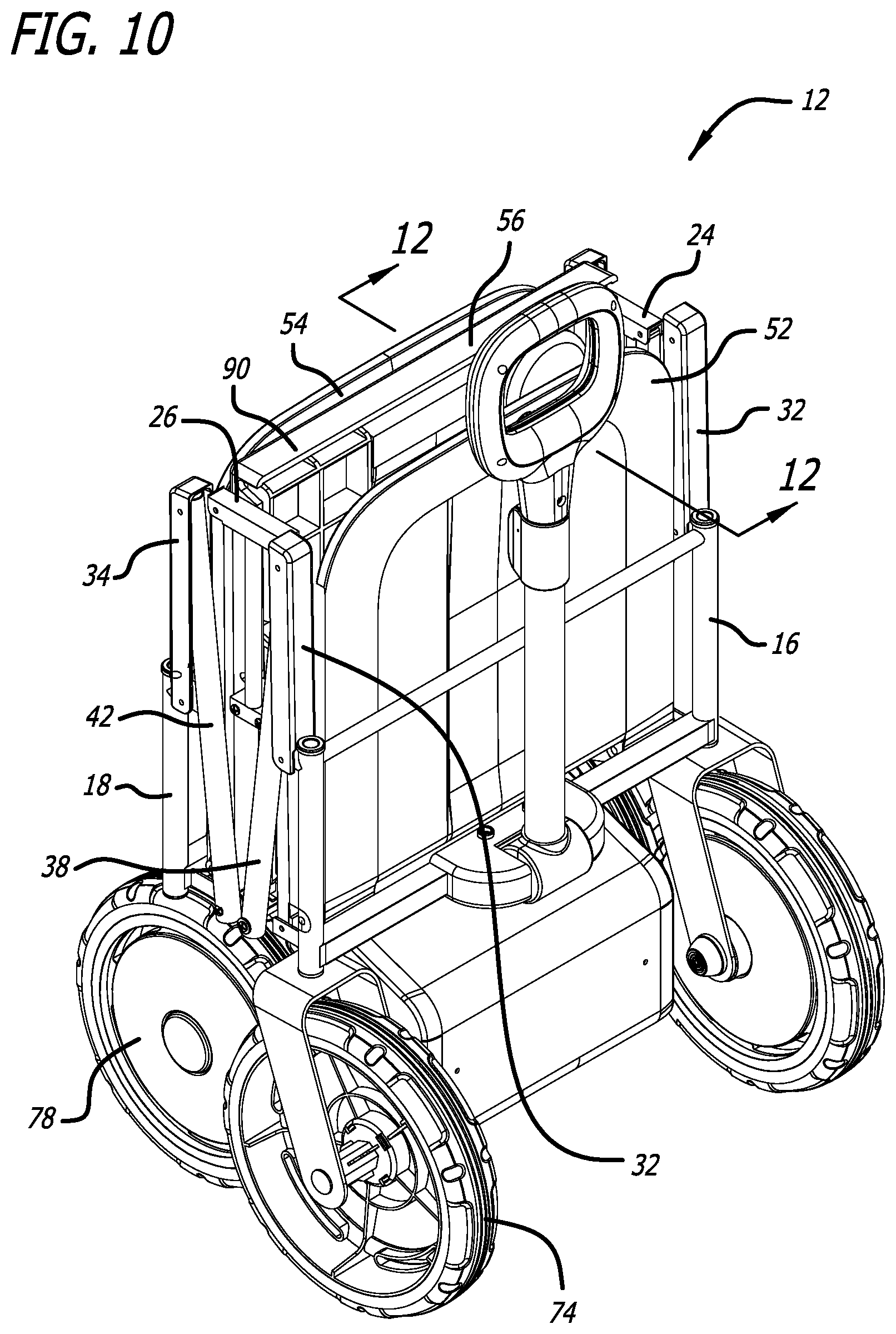
FIG. 10 is a perspective view of the foldable wagon of FIG. 1 in the folded configuration and with the housing structure removed.
FIG. 11 is a side view of the foldable wagon of FIG. 10 in the folded configuration.
FIG. 12 is a cross-sectional perspective view about line 12-12 of FIG. 10.
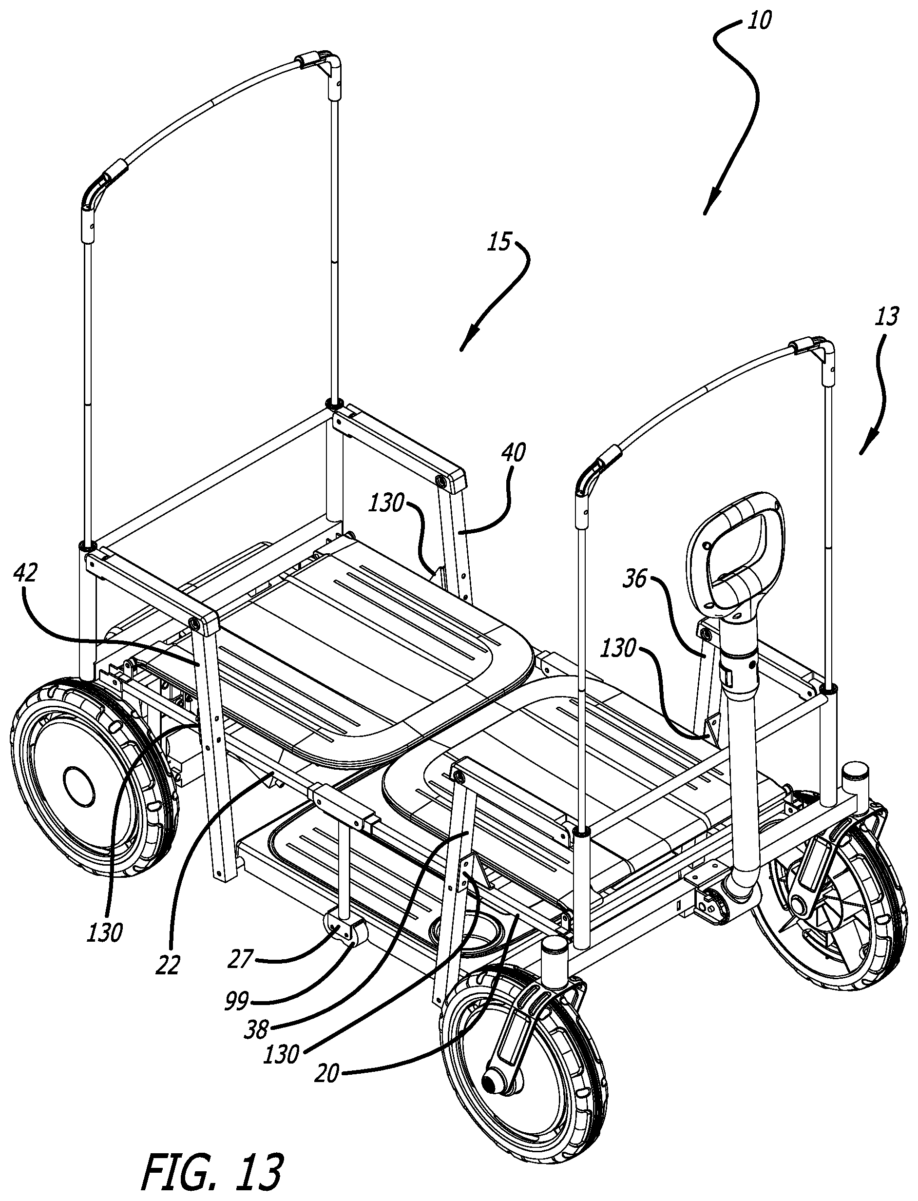
FIG. 13 is a top perspective front view of another embodiment of a foldable wagon with the seat backs in the down orientation and a canopy frame connected to the wagon.
FIG. 14 is a partial perspective view of the front frame structure of the foldable wagon of FIG. 13.
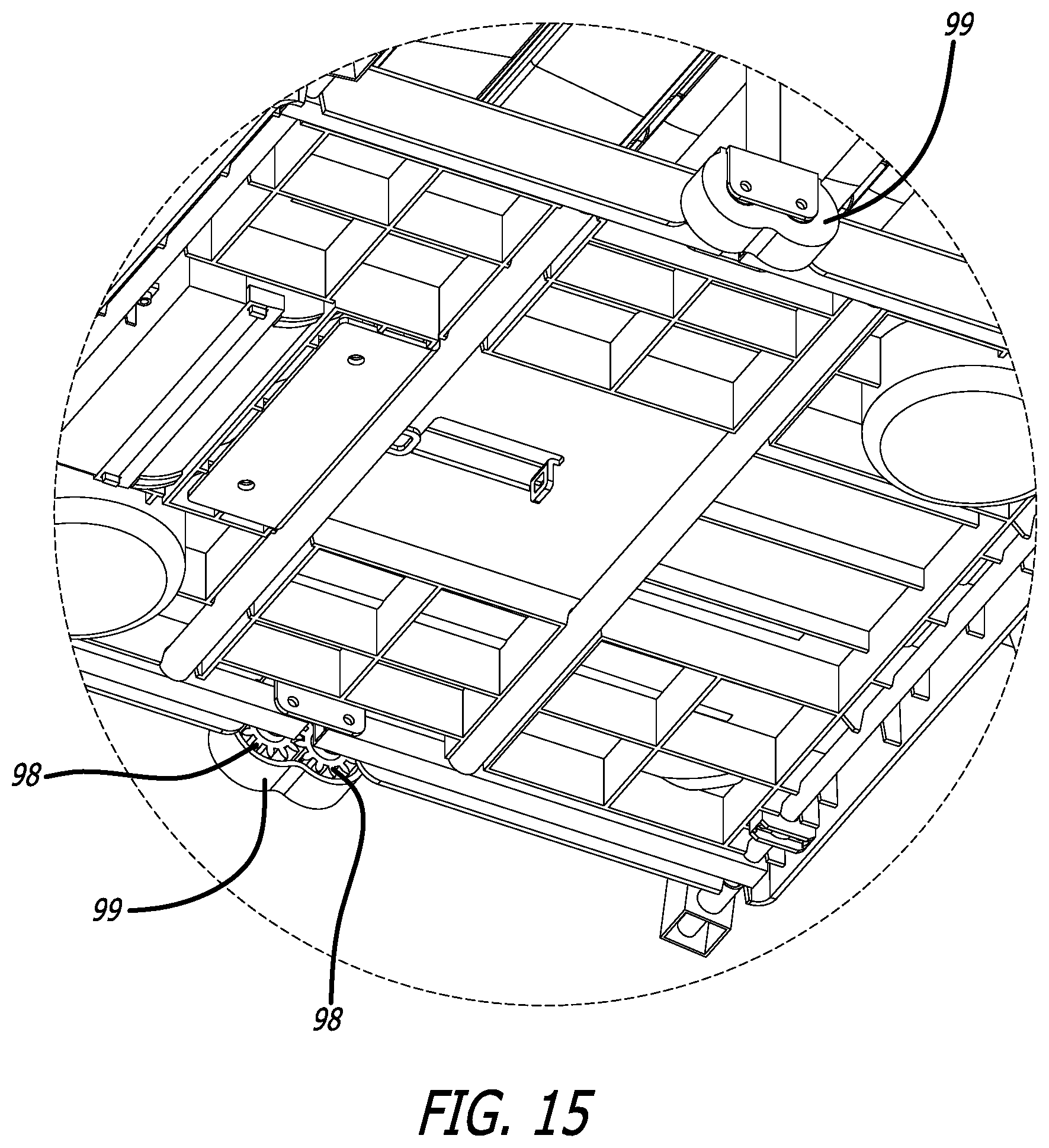
FIG. 15 is a partial perspective view of a folding mechanism for the foldable wagon of FIG. 13.
FIG. 16 is a top view of the foldable wagon of FIG. 13.
DETAILED DESCRIPTION
While the foldable wagon discussed herein is susceptible of embodiments in many different forms, there is shown in the drawings, and will herein be described in detail, preferred embodiments with the understanding that the present description is to be considered as an exemplification of the principles of the foldable wagon and are not intended to limit the broad aspects of the disclosure to the embodiments illustrated.
Referring now to the figures, and initially to FIGS. 1 and 2, in one embodiment a foldable wagon 10 includes a collapsible frame assembly 12 that is moveable and configurable between an unfolded or use configuration (FIGS. 1-6) and a collapsed or folded configuration (FIGS. 7-12). In one embodiment, the foldable wagon 10 also includes a housing assembly 14 that defines sidewalls of the wagon 10. In a preferred embodiment, the housing assembly 14 is preferably made of a flexible material, such as fabric, and is therefore referred to as the fabric assembly 14.
The foldable wagon 10 is shown with the housing assembly 14 (FIG. 1), and without the housing assembly 14 (FIGS. 2-12), to better disclose the collapsible frame assembly 12. The flexible housing 14 is preferably secured about a perimeter of the foldable wagon 10, either inside of the collapsible frame 12, outside the collapsible frame 12 or both inside and outside the collapsible frame 12.
In one embodiment, as best shown in FIG. 2, the collapsible frame assembly 12 comprises a front frame assembly 13 and a rear frame assembly 15. The front frame assembly 13 may comprise, among other structure, a first front side assembly 17, a second front side assembly 19 spaced apart from the first front side assembly 17, and a front frame 16 joining the first front side assembly 17 and the second front side assembly 19. The rear frame assembly 15 may comprise, among other structure, a first rear side assembly 21, a second rear side assembly 23 spaced apart from the first rear side assembly 21, and a rear frame 18 joining the first rear side assembly 21 and the second rear side assembly 23.
In various embodiments the frame assembly 12 also comprises first and second front seat linkages 20 having first and second ends, and first and second rear seat linkages 22 having first and second ends. The first end of the first front seat linkage 20 is preferably pivotally connected to the front frame 16, and the first end of the second front seat linkage 20 is pivotally connected to the front frame 16. Further, the second end of the first front seat linkage 20 is preferably pivotally connected to a first upper pivot bracket 24, and the second end of the second front seat linkage 20 is preferably pivotally connected to a second upper pivot bracket 26. The first end of the rear seat linkage 22 is preferably pivotally connected to the rear frame 18, and the first end of the second rear seat linkage 22 is preferably pivotally connected to the rear frame 18. Further, the second end of the first rear seat linkage 22 is preferably pivotally connected to the first upper pivot bracket 24, and the second end of the second rear seat linkage 22 is preferably pivotally connected to the second upper pivot bracket 26. Accordingly, the first upper pivot bracket 24 joins the first front seat linkage 20 and the first rear seat linkage 22 (i.e., an upper portion of the front frame assembly 13 to an upper portion of the rear frame assembly 15), and the second upper pivot bracket 26 joins the second front seat linkage 20 and the second rear seat linkage 22 (i.e., an upper portion of the front frame assembly 13 to an upper portion of the rear frame assembly 15).
As shown in FIG. 2, a first center linkage 28 extends from the first upper pivot bracket 24 to a first lower pivot bracket 25, and a second center linkage 30 extends from the second upper pivot bracket 26 to a second lower pivot bracket 27. The first lower pivot bracket 25 pivotally connects a first side of a front foot well support 44 to a first side of a rear foot well support 46 (i.e., a lower portion of the front frame assembly 13 to a lower portion of the rear frame assembly 15), and the second lower pivot bracket 27 pivotally connects a second side of the front foot well support 44 to a second side of the rear foot well support 46 (i.e., a lower portion of the front frame assembly 13 to a lower portion of the rear frame assembly 15). In a preferred embodiment the front foot well support 44 is provided between the first front side assembly 17 and the second front side assembly 19, and the rear foot well support 46 is provided between the first rear side assembly 21 and the second rear side assembly 23. Accordingly, in one embodiment, the frame structure extending from the front frame 16 to the first and second center linkages 28, 30 is referred to as the front frame assembly 13, and the frame structure extending from the rear frame 18 to the first and second center linkages 28, 30 is referred to as the rear frame assembly 15.
The frame assembly 12 may also have first and second front armrests 32, and first and second rear armrests 34. The first front armrest 32 is preferably pivotally connected to the front frame 16, and the second front armrest 32 is similarly preferably pivotally connected to the front frame 16. Similarly, the first rear armrest 34 is preferably pivotally connected to the rear frame 18, and the second rear armrest 34 is preferably pivotally connected to the rear frame 18. A first front vertical linkage 36 is provided that has a first end and a second end. The first end of the first front vertical linkage 36 is pivotally connected to the first front armrest 32 and the second end of the first front vertical linkage 36 is pivotally connected to the front foot well support 44. A second front vertical linkage 38 is provided that has a first end and a second end. The first end of the second front vertical linkage 38 is pivotally connected to the second front armrest 32 and the second end of the second front vertical linkage 38 is pivotally connected to the front foot well support 44. A first rear vertical linkage 40 is provided that has a first end and a second end. The first end of the first rear vertical linkage 40 is pivotally connected to the first rear armrest 34 and the second end of the first rear vertical linkage 40 is pivotally connected to the rear foot well support 46. A second rear vertical linkage 42 is provided that has a first end and a second end. The first end of the second rear vertical linkage 42 is pivotally connected to the first rear armrest 34 and the second end of the second rear vertical linkage 42 is pivotally connected to the rear foot well support 46. The collapsible frame assembly 12 also comprises a footrest 56 over the front and rear foot well supports 44, 46. The footrest 56 preferably covers a portion of the front frame assembly and a portion of the rear frame assembly.
The collapsible frame assembly 12 may also comprise a front seat 48 between the first front side assembly 17 and the second front side assembly 19, and a rear seat 50 between the first rear side assembly 21 and the second rear side assembly 23. In an alternate embodiment, the frame assembly 12 has a front backrest 52 and a rear backrest 54. As best shown in FIG. 2, in one embodiment the front seat 48 is fixedly connected to fixed supports 82 extending between the first front seat linkage 20 and the second front seat linkage 20. Similarly, in one embodiment, the rear seat 50 is fixedly connected to fixed supports 84 extending between the first rear seat linkage 22 and the second rear seat linkage 22. While the seat bottoms 48 and 50 are fixed in place, in a preferred embodiment the backrests 52 and 54 are pivotally connected to the wagon frame assembly 12 to be able to move between a raised and folded position. Specifically, in one embodiment the front backrest 52 is pivotally connected to the front frame assembly at the first and second front seat linkages 20, and the rear backrest 54 is pivotally connected to the rear frame assembly at the first and second rear seat linkages 22. The front and rear backrests 52, 54 can be pivoted toward the footrest 56 so that they lay flat against the seats 48, 50.
In one embodiment the front frame 16 is a box-like structure and comprises a lower horizontal member 58, an upper horizontal member 60, a first vertical support 62 and a second vertical support 64. Two front caster wheel assemblies 74 to allow for steering of the wagon 10 are preferably connected to the front frame 16. In an alternate embodiment, as shown in FIGS. 13-16, the front caster wheel assemblies 74 may be connected to the front frame 16 exterior to the side of the front frame assembly so that the front wheels 74 nest outside of the rear wheels 78 in the folded configuration. Additionally, additional support is provided for the wagon 10 by having the front wheels further outward. A pull handle 76 is also connected to the front frame 16.
As shown in FIGS. 2 and 3, in one embodiment the rear frame 18 is also a box-like structure and comprises a lower horizontal member 66, an upper horizontal member 68, a first vertical support 70 and a second vertical support 72. Rear wheels 78 may be connected to the rear frame 18. In the embodiments shown, a drive assembly 80 is provided. The drive assembly 80 includes one or more motors (not shown), a motor controller (not shown), and a power supply 81. In this embodiment the rear wheels 78 are part of the drive assembly 80 that is connected to the rear frame 18. As best shown in FIGS. 10 and 11, the front wheels 74 are outboard of the rear wheels 78 to provide additional stability for the wagon 10 and also to provide clearance for each of the wheels during folding of the wagon 10 as shown in FIGS. 7-12. In one embodiment, the rear wheels are connected to the rear frame assembly interior to a side of the rear frame assembly.
As shown in FIGS. 2-3 and 7-9, the first and second rear vertical linkages 40, 42 are pivotally connected about a mid-location of the vertical linkages 40, 42 to the first and second rear seat linkages 22. Similarly, the first and second front vertical linkages 36, 38 are pivotally connected about a mid-location of the vertical linkages 36, 38 to the first and second front seat linkages 20.
Further, the first end 102 of each of the first and second front seat linkages 20 is pivotally connected to the front frame 16. The second end 104 of the first front seat linkage 20 is pivotally connected to the first pivot bracket 24, and the second end 106 of the second front seat linkage 20 is pivotally connected to the second pivot bracket 26. Similarly, the first end 108 of each of the first and second rear seat linkages 22 is pivotally connected to the rear frame 18. And, the second end 110 of the first rear seat linkage 22 is pivotally connected to the first pivot bracket 24, and the second end 112 of the second rear seat linkage 22 is pivotally connected to the second pivot bracket 26.
Referring to FIGS. 2, 3, 5 and 7-12, the front and rear armrests 32, 34 are also pivotally connected to the collapsible frame assembly 12. The first front armrest 32 is pivotally connected at its first end 114 to the front frame 16 and at its second end 116 to the first front vertical linkage 36. The second front armrest 32 is pivotally connected at its first end 118 to the front frame 16 and at its second end 120 to the second front vertical linkage 38. The first rear armrest 34 is pivotally connected at its first end 122 to the rear frame 18 and at its second end 124 to the first rear vertical linkage 40. The second rear armrest 34 is pivotally connected at its first end 126 to the rear frame 18 and at its second end 128 to the second rear vertical linkage 42.
In one embodiment, the rear foot well support 46 has a first end 92 and a second end 94. And, in one embodiment, the front foot well support 44 has a first end 100 and a second end 96. Referring, for example, to FIG. 9, in one embodiment, the footrest 56 is connected to the rear foot well support 46. Specifically, in one embodiment the first end 88 of the footrest 56 is connected to the first end 92 of the rear foot well support 46. Additionally, the footrest 56 is connected to the second end 94 of the rear foot well support 46. The footrest 56, however, is not directly connected to the front foot well support 44, and instead rests on the front foot well support 44 in the lower position as shown in FIGS. 2-4.
In an alternate embodiment, as best shown in FIGS. 13 and 14, support brackets 130 are provided to provide support and additional rigidity to the wagon frame in the open or use position. For example, one support bracket 130 is connected to each seat linkage 20, 22. Each support bracket 130 has an angled surface to engage the respective vertical linkage 36, 38, 40, 42 when the wagon 10 is in the use position (see FIG. 13). The angled surface of the support bracket 130 operates as a stop for the vertical linkages 36, 38, 40, 42.
To fold the foldable wagon 10, the user first grasps the handle 86 in the footrest 56. As best shown in FIGS. 9 and 12, the handle 86 is built into the body of the footrest 56. In a preferred embodiment, the footrest 56 is pivotally connected to the frame assembly 12 at a first end 88 between the first rear vertical linkage 40 and the second rear vertical linkage 42, and the second end 90 of the footrest 56 merely rests on the front foot well support 44, but is not connected to the front foot well support 44. Accordingly, in one embodiment the footrest 56 is free at the second end 90 of the footrest 56.
When the footrest 56 is raised by the handle 86 the folding action of the foldable frame assembly 12 is set into action. As best shown in FIGS. 3, 4 and 7-9, by lifting the second end 90 of the footrest 56, the footrest 56 is pivoted upwardly about a pivot connection between the rear foot well support 46 and the rear vertical linkages 40, 42. Accordingly, as the second end 90 of the footrest 56 is lifted, the first end 88 of the footrest 56 and the first end support 92 of the rear foot well support 46 are pivoted with respect to the lower ends of the first and second rear vertical linkages 40, 42. Similarly, when the second end 90 of the footrest 56 is lifted, the second end support 94 of the rear foot well support 46 is simultaneously pivoted upwardly.
In one embodiment, a timing member 98, also referred to as a synching member 98, connects the front frame assembly 13 to the rear frame assembly 15. Accordingly, in one embodiment, the rear foot well support 46 is pivotally connected to the front foot well support 44 by the timing or synching members 98. The timing members 98 ensure that the rear foot well support 46 and the front foot well support 44 pivot, in opposite directions, simultaneously. In one embodiment the timing members 98 are a series of gears 98, such as a first gear 98 connected to the front frame assembly and a mating second gear 98 connected to the rear frame assembly. Further, in an alternate embodiment, as shown in FIGS. 13 and 15, a cover 99 may be provided over the timing members 98 for safety purposes.
Accordingly, when the footrest 56 is pivoted upwardly, the second end support 94 of rear foot well support 46 and the second end support 96 of the front foot well support 44 are also both pivoted upwardly together (about opposite pivot points, those being the connection of the rear footwell support 46 with the rear vertical linkages 40, 42 and the connection of the front footwell support 44 with the front vertical linkages 36, 38) at the bottom of the first and second center linkages 28, 30. Similar to how the rear foot well support 46 is pivotally connected to the lower ends of the first and second rear vertical linkages 40, 42, the front foot well support 44 is pivotally connected to the lower ends of the first and second front vertical linkages 36, 38.
In one embodiment, four separate four-bar linkages are created by different pivoting connections at each side of the frame assembly 12, for a total of eight four-bar linkages. A first four bar linkage is created by the pivotal connection of the first front armrest 32, the first front vertical linkage 36, the first front seat linkage 20 and the front frame 16. The second four bar linkage is created by the pivotal connection of the second front armrest 32, the second front vertical linkage 38, the second front seat linkage 20 and the front frame 16. The third four bar linkage is created by the pivotal connection of the first front seat linkage 20, the first center linkage 28, the front foot well support 44 and the first front vertical linkage 36. The fourth four bar linkage is created by the pivotal connection of the second front seat linkage 20, the second center linkage 30, the front foot well support 44 and the second front vertical linkage 38. The fifth four bar linkage is created by the pivotal connection of the first rear armrest 34, the first rear vertical linkage 40, the first rear seat linkage 22 and the rear frame 18. The sixth four bar linkage is created by the pivotal connection of the second rear armrest 34, the second rear vertical linkage 42, the second rear seat linkage 22 and the rear frame 18. The seventh four bar linkage is created by the pivotal connection of the first rear seat linkage 22, the first center linkage 28, the rear foot well support 46 and the first rear vertical linkage 40. The eighth four bar linkage is created by the pivotal connection of the second rear seat linkage 22, the second center linkage 30, the rear foot well support 46 and the second rear vertical linkage 42.
Accordingly, as explained above, when the footrest 56 is raised by the handle 86 the folding action of the foldable frame assembly 12 is set into action. Referring to FIGS. 7-12, the eight four-bar linkages described above fold to collapse the collapsible frame assembly 12 so that the front section of the frame assembly (i.e., from the first and second pivot brackets 24, 26 to the front frame 16) moves toward the center linkages 28, 30, and the rear section of the frame assembly (i.e., from the first and second pivot brackets 24, 26 to the rear frame 18) moves toward the center linkages 28, 30. The final folded frame assembly 12 is shown in FIGS. 10-12.
To unfold the foldable frame assembly 12 into the unfolded configuration the reverse operation is conducted. Accordingly, the front section of the frame assembly moves distal the center linkages and the rear section of the frame assembly moves distal the center linkages in the opposite direction.
Several alternative embodiments and examples have been described and illustrated herein. A person of ordinary skill in the art would appreciate the features of the individual embodiments, and the possible combinations and variations of the components. A person of ordinary skill in the art would further appreciate that any of the embodiments could be provided in any combination with the other embodiments disclosed herein. Additionally, the terms "first," "second," "third," and "fourth" as used herein are intended for illustrative purposes only and do not limit the embodiments in any way. Further, the term "plurality" as used herein indicates any number greater than one, either disjunctively or conjunctively, as necessary, up to an infinite number. Additionally, the term "having" as used herein in both the disclosure and claims, is utilized in an open-ended manner.
It will be understood that the invention may be embodied in other specific forms without departing from the spirit or central characteristics thereof. The present examples and embodiments, therefore, are to be considered in all respects as illustrative and not restrictive, and the invention is not to be limited to the details given herein. Accordingly, while the specific embodiments have been illustrated and described, numerous modifications come to mind without significantly departing from the spirit of the invention and the scope of protection is only limited by the scope of the accompanying Claims.
* * * * *
D00000
D00001
D00002
D00003
D00004
D00005
D00006
D00007
D00008
D00009
D00010
D00011
D00012

D00013
D00014

D00015
D00016

XML
uspto.report is an independent third-party trademark research tool that is not affiliated, endorsed, or sponsored by the United States Patent and Trademark Office (USPTO) or any other governmental organization. The information provided by uspto.report is based on publicly available data at the time of writing and is intended for informational purposes only.
While we strive to provide accurate and up-to-date information, we do not guarantee the accuracy, completeness, reliability, or suitability of the information displayed on this site. The use of this site is at your own risk. Any reliance you place on such information is therefore strictly at your own risk.
All official trademark data, including owner information, should be verified by visiting the official USPTO website at www.uspto.gov. This site is not intended to replace professional legal advice and should not be used as a substitute for consulting with a legal professional who is knowledgeable about trademark law.