Indirect gas cooler
Arndt , et al. Feb
U.S. patent number 10,571,204 [Application Number 15/227,005] was granted by the patent office on 2020-02-25 for indirect gas cooler. This patent grant is currently assigned to Modine Manufacturing Company. The grantee listed for this patent is Modine Manufacturing Company. Invention is credited to Daniel Arndt, Marius Dornseif, Alexander Riebel.


| United States Patent | 10,571,204 |
| Arndt , et al. | February 25, 2020 |
Indirect gas cooler
Abstract
An indirect gas cooler is constructed from stacked pairs of plates with fins arranged in between. The stack is arranged in a housing into which the gas flows, flows through the fins, and leaves the housing again. The gas is in thermal exchange with the liquid that flows in the plate pairs and that is introduced into the plate pairs via at least one inlet and is discharged via at least one outlet. A ventilating member is provided in the stack for discharging entrained gases from the liquid. The ventilating member is formed from aligned plate openings which produce a ventilating duct that is hydraulically connected with a liquid space in the stack. The indirect gas cooler can be used to cool compressed charge air for an internal combustion engine.
| Inventors: | Arndt; Daniel (Reutlingen, DE), Riebel; Alexander (Stuttgart, DE), Dornseif; Marius (Filderstadt, DE) | ||||||||||
|---|---|---|---|---|---|---|---|---|---|---|---|
| Applicant: |
|
||||||||||
| Assignee: | Modine Manufacturing Company
(Racine, WI) |
||||||||||
| Family ID: | 57853851 | ||||||||||
| Appl. No.: | 15/227,005 | ||||||||||
| Filed: | August 3, 2016 |
Prior Publication Data
| Document Identifier | Publication Date | |
|---|---|---|
| US 20170038168 A1 | Feb 9, 2017 | |
Foreign Application Priority Data
| Aug 8, 2015 [DE] | 10 2015 010 287 | |||
| Current U.S. Class: | 1/1 |
| Current CPC Class: | F28F 21/067 (20130101); F28D 9/0056 (20130101); F02B 29/0462 (20130101); F28F 9/001 (20130101); F28D 9/0043 (20130101); F28F 3/086 (20130101); F28F 9/028 (20130101); Y02T 10/12 (20130101); F28F 2275/06 (20130101); F28F 2275/04 (20130101); F28D 2021/0082 (20130101); F28F 2265/18 (20130101); Y02T 10/146 (20130101) |
| Current International Class: | F28F 9/00 (20060101); F28F 3/08 (20060101); F28D 9/00 (20060101); F28F 9/02 (20060101); F28D 21/00 (20060101) |
| Field of Search: | ;165/166,278 |
References Cited [Referenced By]
U.S. Patent Documents
| 2170214 | August 1939 | Morrow |
| 3533465 | October 1970 | Bennett |
| 3604502 | September 1971 | Morse |
| 4011905 | March 1977 | Millard |
| 4480598 | November 1984 | Berrigan |
| 4592418 | June 1986 | Cadars |
| 5575329 | November 1996 | So et al. |
| 5680897 | October 1997 | Kilmer |
| 7669643 | March 2010 | Ekelund |
| 2007/0181105 | August 2007 | Bazika |
| 2011/0108252 | May 2011 | Contet et al. |
| 2011/0168366 | July 2011 | Garret et al. |
| 2012/0285423 | November 2012 | Nguyen |
| 3330710 | Sep 1982 | DE | |||
| 4328448 | Aug 1995 | DE | |||
| 102005005043 | Aug 2006 | DE | |||
Other References
|
Chinese Patent Office Action for Application No. 201610634767.9 dated Feb. 5, 2018 (24 pages, English translation included). cited by applicant . The National Intellectual Property Administration, PRC, Notification of the Second Office Action, Chinese Patent Application No. 201610634767.9, dated Oct. 8, 2018. cited by applicant . The National Intellectual Property Administration, PRC, Notification of the Third Office Action, Chinese Patent Application No. 201610634767.9, dated Apr. 3, 2019 (13 pages). cited by applicant . Examination Report for Indian Patent Application No. 201614026206, Intellectual Property India dated Jun. 28, 2019 (6 pages). cited by applicant . 1st Substantive Examination Requirement for Mexican Patent Application No. Mx/a/2016/010246, Instituto Mexicano de la Propriedad Industrial dated Aug. 27, 2019 (4 pages). cited by applicant. |
Primary Examiner: Zerphey; Christopher R
Assistant Examiner: Ling; For K
Attorney, Agent or Firm: Michael Best & Friedrich LLP Valensa; Jeroen Bergnach; Michael
Claims
What is claimed is:
1. An indirect gas cooler, comprising: a plurality of stacked pairs of plates with fins arranged between adjacent pairs to define a stack within which a cooling liquid flows; a housing surrounding the stack and through which the gas flows to be cooled by the stack; an upper plate including a first depression and a second depression, each of the first depression and the second depression extending from a top surface of the upper plate and each having side walls and a bottom planar wall, wherein each of the bottom planar walls is joined to a top end of the stack; a covering plate extending at least partially over the first depression to at least partially cover the first depression and being at least partially spaced apart from the bottom planar wall of the first depression; an inlet space and an outlet collecting space extending through the stack for the cooling liquid, the inlet space and the outlet collecting space being connected by ducts within each of the pairs of plates; a ventilating duct extending through the stack and being open at a top end of the ventilating duct and at a bottom end of the ventilating duct to receive entrained air from the cooling liquid at the top end of the ventilating duct, dropping the entrained air through the ventilating duct, and draining the entrained air from the ventilating duct at the bottom end of the ventilating duct, wherein the ventilating duct is hydraulically connected to one of the inlet space and the outlet collecting space, wherein the ventilating duct is formed by aligned openings of the plates, and wherein the ventilating duct and said one of the inlet space and the outlet collecting space are hydraulically connected by way of a connecting duct extending within the first depression of the upper plate, the connecting duct being defined by the covering plate and the first depression; and a connecting stub arranged at an end of the stack opposite the upper plate and at the bottom end of the ventilating duct to drain the entrained air from the bottom of the gas cooler, wherein the connecting stub is hydraulically connected to the ventilating duct to form a ventilating member, wherein the connecting stub is aligned with the ventilating duct and extends from an underside of the gas cooler parallel to a stacking direction of the stack in an installed position of the gas cooler.
2. The indirect gas cooler of claim 1, wherein the connecting stub is a first connecting stub, further comprising: a second connecting stub arranged at the end of the stack opposite the upper plate and hydraulically connected to the inlet space to provide a cooling liquid inlet; and a third connecting stub arranged at the end of the stack opposite the upper plate and hydraulically connected to the outlet collecting space to provide a cooling liquid outlet.
3. The indirect gas cooler of claim 2, further comprising a baseplate arranged at the end of the stack opposite the upper plate, the first, second, and third connecting stubs being joined to the baseplate and hydraulically connected to the ventilating duct, the inlet space, and the outlet collecting space through the baseplate.
4. The indirect gas cooler of claim 3, wherein the stack of plate pairs and fins, the baseplate, and the first, second, and third connecting stubs are brazed together in one step.
5. The indirect gas cooler of claim 3, wherein the housing comprises a trough-like part surrounding the stack and an insertion opening through which the stack is inserted into the housing, the insertion opening being closed by the baseplate.
6. The indirect gas cooler of claim 1, wherein the inlet space is defined by aligned inlet-side openings of the plates and the outlet collecting space is defined by outlet side openings of the plates, and wherein the aligned openings forming the ventilating duct are arranged between the inlet-side and the outlet-side plate openings.
7. The indirect gas cooler of claim 1, wherein each of the plurality of stacked pairs of plates includes a cut-out, the ventilating duct and the one of the inlet space and the outlet collecting space to which the ventilating duct is hydraulically connected being arranged on one side of the cut-out and the other of the inlet space and the outlet collecting space being arranged on the other side of the cut-out.
8. The indirect gas cooler of claim 1, wherein the bottom planar wall of the first depression extends from the ventilating duct to one of the inlet space and the outlet collecting space, being joined to the ventilating duct and to one of the inlet space and the outlet collecting space.
9. The indirect gas cooler of claim 1, wherein the bottom planar wall of the first depression has a first aperture extending therethrough in alignment with the ventilating duct and a second aperture extending therethrough in alignment with one of the inlet space and the outlet connecting space.
10. The indirect gas cooler of claim 1, wherein the bottom planar wall of the second depression extends continuously across and caps one of the inlet space and the outlet collecting space.
11. The indirect gas cooler of claim 3, further comprising a lower plate having three lower plate openings, wherein the lower plate is arranged between the stack and the baseplate, being joined to both a bottom end of the stack and to the baseplate and aligned with the stack and the baseplate such that the three lower plate openings are each aligned with one of the baseplate openings and one of the ventilating duct, the inlet space, and the outlet connecting space.
12. A charge air cooler that cools charge air flowing through a housing for an internal combustion engine, comprising: a housing including an air inlet, an air outlet, and an insertion opening, the insertion opening being arranged at a bottom end of the housing; a stack arranged within the housing between the air inlet and the air outlet, the stack including a plurality of fins and a plurality of plates, each of the plurality of plates having an inlet opening, an outlet opening, a cut-out, and a ventilating opening, wherein the inlet openings of the plurality of plates are aligned to define an inlet space of the stack, wherein the outlet openings of the plurality of plates are aligned to define an outlet collecting space of the stack, wherein the ventilating openings of the plurality of plates are aligned to define a ventilating duct of the stack, and wherein each plate of the plurality of plates is paired with another plate of the plurality of plates to define a pair of plates of at least two pairs of plates; an upper plate joined to one of the pairs of plates at a top end of the stack and extending across the inlet space, the outlet collecting space, and the ventilating duct of the stack, the upper plate including a cover extending over the inlet space, a cut-out, a first connection hole aligned with the ventilating duct, a second connection hole aligned with the outlet collecting space, and a connecting duct extending between the first connection hole and the second connection hole; a covering part joined to the upper plate and covering the connecting duct; a lower plate joined to another one of the pairs of plates; and a baseplate joined to the lower plate at a bottom end of the stack and located at the insertion opening to close the insertion opening, the baseplate including three baseplate openings; wherein the upper plate cover closes the inlet space, wherein the inlet space and the outlet collecting space are fluidly connected by a duct within each of pair of plates, wherein at least one fin of the plurality of fins is arranged between the upper plate and the stack, wherein the cut-outs of the plurality of plates are aligned, wherein the cut-out of the upper plate is aligned with the cut-outs of the plurality of plates, wherein the lower plate and the baseplate each extend across the cut-outs, and wherein the ventilating duct extends through the stack adjacent to the cut-outs of the plurality of plates allowing entrained air within the plurality of plates to exit the charge air cooler below the stack through the baseplate.
13. The charge air cooler of claim 12, wherein at least one fin of the plurality of fins is located between the at least two pairs of plates.
14. The charge air cooler of claim 12, wherein the lower plate has three lower plate openings, and wherein the baseplate is aligned with the lower plate such that one of each of the three lower plate openings is aligned with one of each of the baseplate openings.
Description
CROSS-REFERENCE TO RELATED APPLICATIONS
This application claims priority to German Patent Application No. 10 2015 010287, filed Aug. 8, 2015, the entire contents of which are hereby incorporated by reference herein.
BACKGROUND
The invention relates to an indirect gas cooler, in which the gas, for example compressed charge air for an internal combustion engine is cooled by means of a liquid, the air cooler being constructed from stacked pairs of plates with fins which are arranged in between, and being arranged in a housing, into which the gas flows, flows through the fins and leaves the housing again, said housing being in thermal exchange with the liquid which flows in the plate pairs, can be introduced into the plate pairs via at least one inlet and via plate openings which are aligned in the stack, and can be discharged via at least one outlet by means of other aligned plate openings, and having a ventilating member for discharging entrained air in the liquid.
The described indirect gas cooler was filed recently at the DPMA and was given the reference number DE 10 2014 012 179.8. The ventilating member of the earlier application consists of an inserted small tube.
SUMMARY
It is one object of the invention to propose alternative embodiments of the earlier application which permit effective ventilation, without it being necessary for a small tube or additional component of the like to be inserted, as a result of which possibly costs are to be reduced and other advantages are to be achieved.
One aspect of the invention consists in that the ventilating member is formed from further aligned plate openings which produce a ventilating duct which is in a connection with a liquid space which is present in the stack. The liquid space is preferably an outlet collecting space which is configured in the stack for the liquid.
All the plates preferably have the abovementioned further aligned plate openings, for which reason the ventilating duct extends through the entire stack.
It is advantageous in terms of design and manufacturing technology if the further aligned plate openings are preferably of identical configuration with regard to their edge formation to the aligned inlet-side and to the aligned outlet-side plate openings. However, they are preferably considerably smaller with regard to their cross-sectional size than the inlet-side and/or the outlet-side plate openings.
The further aligned plate openings are very preferably also situated in the vicinity of the abovementioned plate openings, in order for it to be possible to produce a very short hydraulic connection, for example, from an outlet space for the liquid toward the ventilating duct which is formed from the further plate openings.
The ventilating member comprises a connecting duct to the liquid space which is preferably the outlet-side collecting space, and a connection stub or a line which extends through an opening to outside of the housing.
It is of particular advantage in terms of manufacturing technology that the entire ventilating member is a constituent part of the brazed stack, that is to say the ventilating member is also brazed in one step with the hard brazing of the stack in a brazing furnace and accordingly does not have to be subsequently installed. As a result, the mechanical seal which was necessary in the abovementioned older application but which is often unreliable becomes superfluous.
The invention will be described in two exemplary embodiments using the appended drawings. The description can contain further features which can prove to be essential distinguishing features.
BRIEF DESCRIPTION OF THE DRAWINGS
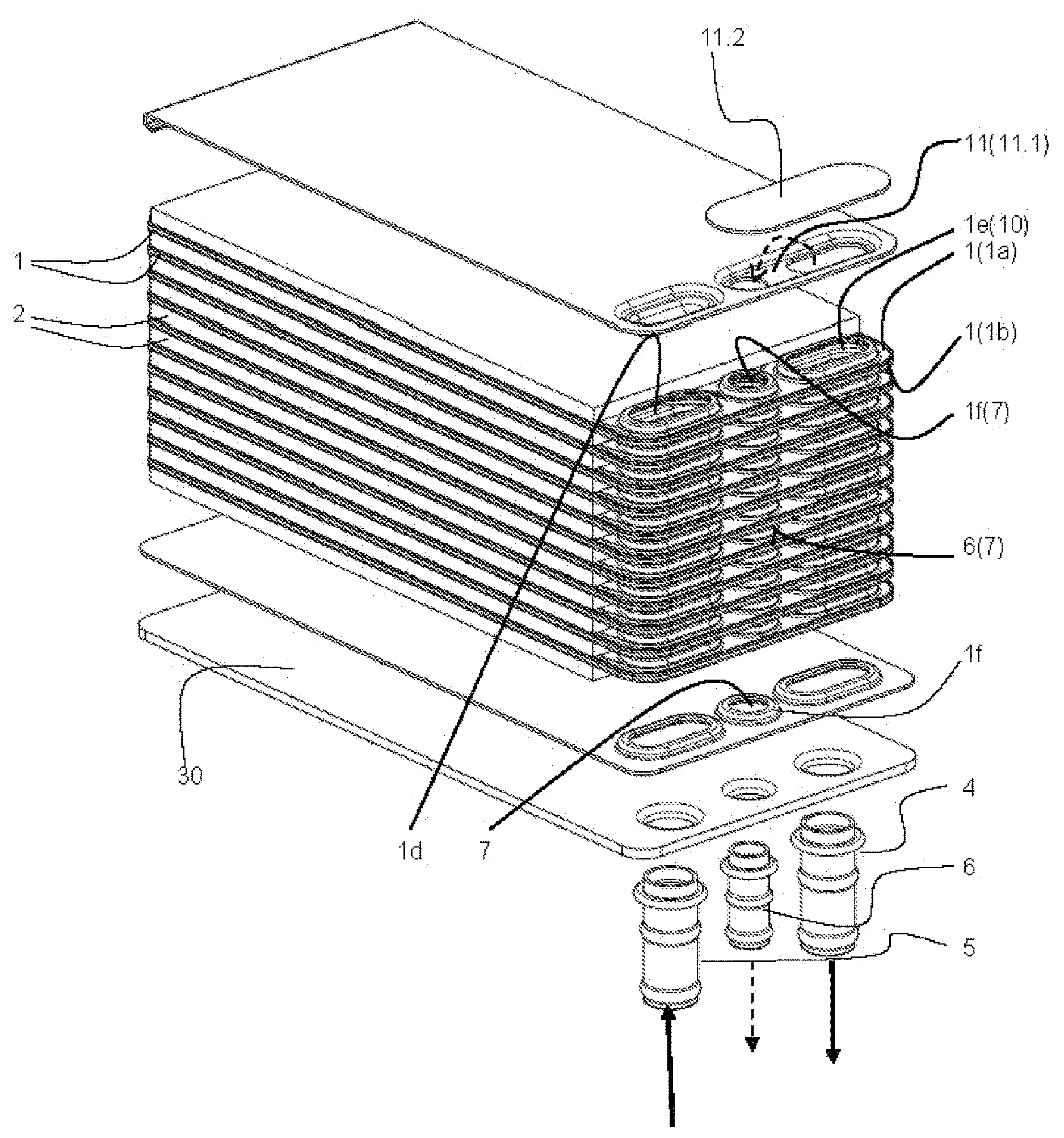
FIG. 1 shows a stack of plates and fins of a gas cooler in a first exemplary embodiment, partially in an exploded illustration.
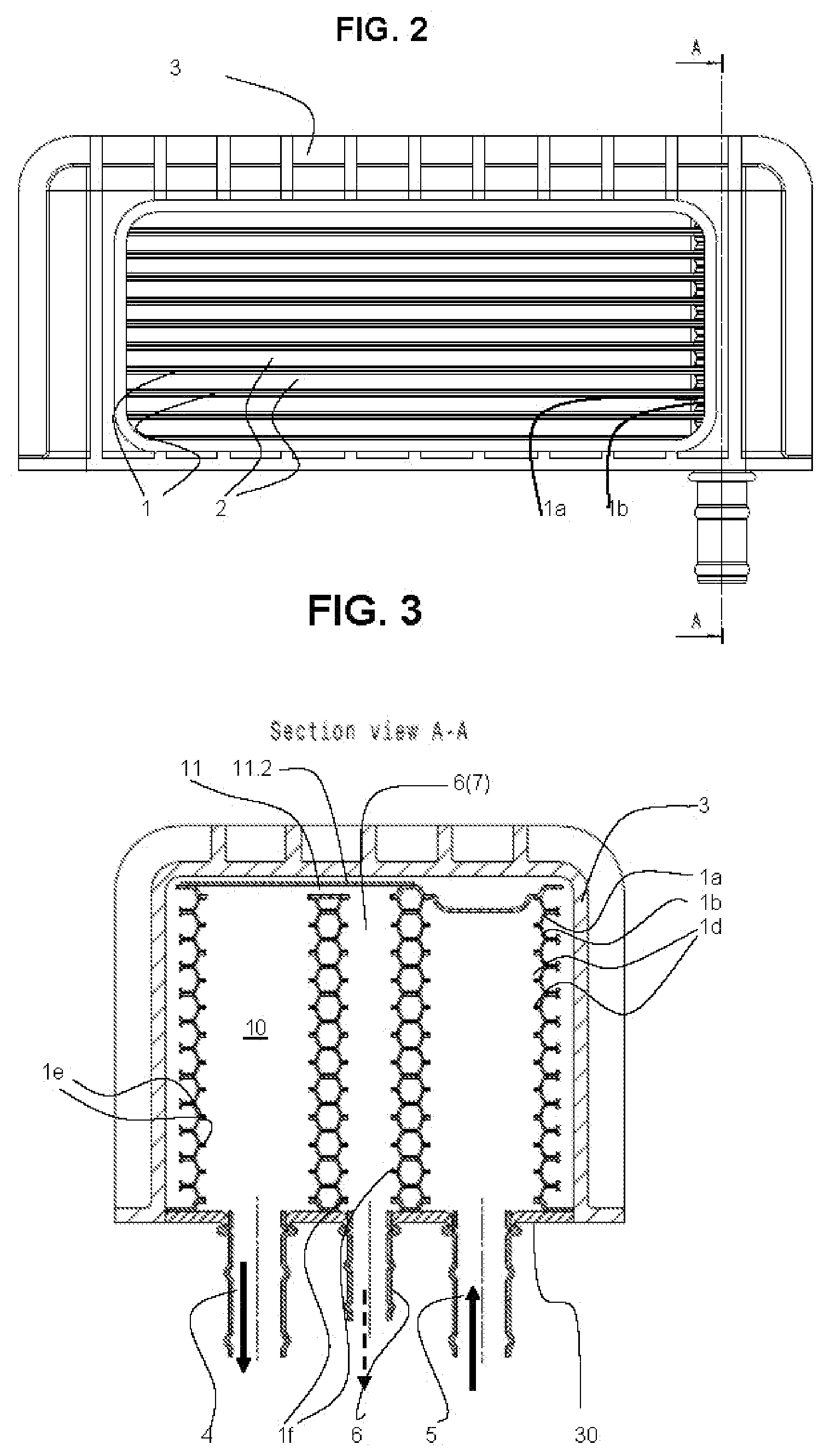
FIG. 2 shows the stack from FIG. 1, arranged in a housing.
FIG. 3 shows a section A-A from FIG. 2.
FIG. 4 shows a perspective view of the subject matter according to FIG. 2.
FIG. 5 shows a second exemplary embodiment in a view which is similar to FIG. 1.
FIG. 6 shows a section through the second exemplary embodiment in a similar manner to FIG. 3.
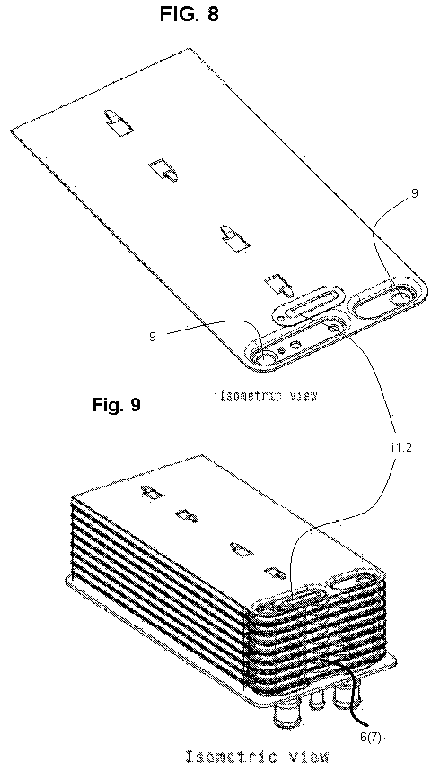
FIGS. 7-9 show a slightly modified further exemplary embodiment.
FIGS. 10 and 11 show a different modification.
DETAILED DESCRIPTION
Before any embodiments of the invention are explained in detail, it is to be understood that the invention is not limited in its application to the details of construction and the arrangement of components set forth in the following description or illustrated in the accompanying drawings. The invention is capable of other embodiments and of being practiced or of being carried out in various ways. Also, it is to be understood that the phraseology and terminology used herein is for the purpose of description and should not be regarded as limiting. The use of "including," "comprising," or "having" and variations thereof herein is meant to encompass the items listed thereafter and equivalents thereof as well as additional items. Unless specified or limited otherwise, the terms "mounted," "connected," "supported," and "coupled" and variations thereof are used broadly and encompass both direct and indirect mountings, connections, supports, and couplings. Further, "connected" and "coupled" are not restricted to physical or mechanical connections or couplings.
By way of the indirect gas cooler which is depicted in the illustrations, compressed charge air for an internal combustion engine is cooled by means of a liquid. It might also be an exhaust gas or another gas mixture. The use of the gas cooler in conjunction with an internal combustion engine is also optional.
The gas cooler is constructed from stacked pairs 1a, 1b of plates 1 with fins 2 which are arranged in between. The stack is arranged in a housing 3. The charge air flows into the housing 3, flows through the fins 2 and subsequently leaves the housing 3 in the cooled state (FIGS. 2 and 4). The liquid which brings about the abovementioned cooling action flows in the plate pairs 1a, 1b. The liquid flows into the plate pairs 1a, 1b via an inlet 5 and via inlet-side plate openings 1d which are aligned in the stack. After flowing through ducts which are present in the plate pairs 1a, 1b, said liquid is discharged again via at least one outlet 4 by means of aligned outlet-side plate openings 1e (FIG. 1, inter alia).
Entrained gas is sometimes present in the liquid, which impairs the efficiency of the heat exchanger as is known. In order to remove the entrained gas at least largely from the liquid, a ventilating member 6 is provided in the stack.
The ventilating member 6 is formed from further aligned plate openings 1f which produce a ventilating duct 7. The ventilating duct 7 is in a hydraulic connection 11 with a liquid space 10 which is present in the stack. The liquid space 10 is the outlet collecting space which is produced by way of the outlet-side plate openings 1d which are aligned in the stack.
The selection of the inlet space as liquid space 10 causes the entrained gas to be removed before it flows through the plate pairs 1a, 1b. Nevertheless, the liquid circulates in a closed circuit, and it is important to export the entrained gas from the circuit.
As can be seen directly from most figures, the plate openings 1f which form the ventilating duct 7 are situated close beside the outlet-side plate openings 1d. This has the advantage that the hydraulic connection 11 can be very short.
In relation to the positions of inlet 5 and outlet 4 which are present in the exemplary embodiments, it is relatively appropriate that the plate openings 1f which form the ventilating duct 7 are arranged between the inlet-side and the outlet-side plate openings 1d, 1e.
In conjunction with the above, it is then provided that the plates 1a, 1b are configured with a plate cut-out 8 which lies between the inlet 5 and the outlet 4, the further aligned plate openings 1f and the inlet-side plate openings 1d being arranged on one side of the plate cut-out 8 and the outlet-side plate openings 1e being arranged on the other side of the plate cut-out 8 (FIGS. 5 and 6).
FIGS. 1, 9, 10 and 11 show embodiments without plate cut-outs 8.
The hydraulic connection 11 which has already been addressed is realized by means of a connecting duct 11.1 which extends along an upper plate and comprises a covering part 11.2 which lies on the upper plate. Configuring the duct 11.1 on the upper plate is favorable with regard to the effectiveness, and it also appears to be advantageous in terms of the implementation. There are various designs with regard to the covering plate 11.2. In FIG. 11, a further plate of the same size is placed onto the upper plate, which further plate represents the covering plate 11.2. Since the plate thicknesses have been reduced considerably, something of this type can be advantageous. In FIGS. 1, 3, 5 and 6, a relatively small, planar covering plate 11.2 has been used, in order to configure the connecting duct 11.1. In the embodiment according to FIGS. 7 and 8, the covering plate 11.2 is of even somewhat smaller design and has a molded bead. Advantages can be associated with the different designs with regard to the behavior in respect of internal pressure.
It is advantageous that the stack lies on a stable base plate 30, the base plate 30 closing an insertion opening of the housing 3. For example, FIGS. 3 and 4 show a base plate 30 which is welded on the edge side in the insertion opening. The housing 3 has been manufactured, for example, from cast aluminum.
However, the housing 3 can also be a plastic housing. It can consist of an upper and a lower trough-like housing half. It is advantageous, however, if the housing 3 consists of a trough-like part and a planar cover part, produced by means of the abovementioned base plate 30 (FIGS. 2-4 and 6).
The inlet 5, the outlet 4 and a connecting stub 60 of the ventilating member 6 are arranged on an underside of the gas cooler in an installed position of the gas cooler.
The inlet 5 and the outlet 4 are also equipped with corresponding connecting stubs 40, 50. All the stubs 40, 50, 60 have been brazed into corresponding openings of the base plate 30. Accordingly, no further mechanical seal is required, which seal tends to leak after certain service times and under the effect of vibrations.
A further noteworthy feature of the embodiment according to FIGS. 7-9 consists in that, in two of its corner regions, the upper plate contains shaped-out moldings which bear the designation 9. Said shaped-out moldings 9 (of circular design in the exemplary embodiment) bring about simpler pre-assembly of the plate stack, since they produce a positioning aid.
Various alternatives to the certain features and elements of the present invention are described with reference to specific embodiments of the present invention. With the exception of features, elements, and manners of operation that are mutually exclusive of or are inconsistent with each embodiment described above, it should be noted that the alternative features, elements, and manners of operation described with reference to one particular embodiment are applicable to the other embodiments.
The embodiments described above and illustrated in the figures are presented by way of example only and are not intended as a limitation upon the concepts and principles of the present invention. As such, it will be appreciated by one having ordinary skill in the art that various changes in the elements and their configuration and arrangement are possible without departing from the spirit and scope of the present invention.
* * * * *
D00000
D00001
D00002
D00003
D00004
D00005
D00006
D00007
XML
uspto.report is an independent third-party trademark research tool that is not affiliated, endorsed, or sponsored by the United States Patent and Trademark Office (USPTO) or any other governmental organization. The information provided by uspto.report is based on publicly available data at the time of writing and is intended for informational purposes only.
While we strive to provide accurate and up-to-date information, we do not guarantee the accuracy, completeness, reliability, or suitability of the information displayed on this site. The use of this site is at your own risk. Any reliance you place on such information is therefore strictly at your own risk.
All official trademark data, including owner information, should be verified by visiting the official USPTO website at www.uspto.gov. This site is not intended to replace professional legal advice and should not be used as a substitute for consulting with a legal professional who is knowledgeable about trademark law.