Fuel injection throttle body
Flynn , et al. Feb
U.S. patent number 10,570,866 [Application Number 15/986,571] was granted by the patent office on 2020-02-25 for fuel injection throttle body. This patent grant is currently assigned to Holley Performance Products, Inc.. The grantee listed for this patent is Holley Performance Products, Inc.. Invention is credited to James Dralle, Doug Flynn, Amy Gieske, Charles Jenckes, Corey Spainhoward.


| United States Patent | 10,570,866 |
| Flynn , et al. | February 25, 2020 |
Fuel injection throttle body
Abstract
A throttle body fuel injection system including a throttle body with at least one air intake, a fuel injector coupled to the throttle body at a fuel port and an annular ring coupled to the cylindrical inner wall of the air intake. The annular ring includes a primary fuel discharge orifice adjacent to the fuel port and a plurality of secondary fuel discharge orifices arranged radially around the annular ring for spraying atomized fuel into the air intake.
| Inventors: | Flynn; Doug (Bowling Green, KY), Dralle; James (Bowling Green, KY), Gieske; Amy (Loogootee, IN), Jenckes; Charles (Harrisburg, NC), Spainhoward; Corey (Bowling Green, KY) | ||||||||||
|---|---|---|---|---|---|---|---|---|---|---|---|
| Applicant: |
|
||||||||||
| Assignee: | Holley Performance Products,
Inc. (Bowling Green, KY) |
||||||||||
| Family ID: | 52825308 | ||||||||||
| Appl. No.: | 15/986,571 | ||||||||||
| Filed: | May 22, 2018 |
Prior Publication Data
| Document Identifier | Publication Date | |
|---|---|---|
| US 20180266376 A1 | Sep 20, 2018 | |
Related U.S. Patent Documents
| Application Number | Filing Date | Patent Number | Issue Date | ||
|---|---|---|---|---|---|
| 14156813 | Jan 16, 2014 | 10012197 | |||
| 61892706 | Oct 18, 2013 | ||||
| Current U.S. Class: | 1/1 |
| Current CPC Class: | F02M 35/10216 (20130101); F02M 69/043 (20130101); F02M 61/1826 (20130101); F02D 9/1035 (20130101); F02M 61/184 (20130101); F02D 9/109 (20130101) |
| Current International Class: | F02M 61/18 (20060101); F02D 9/10 (20060101); F02M 69/04 (20060101); F02M 35/10 (20060101) |
| Field of Search: | ;239/562 |
References Cited [Referenced By]
U.S. Patent Documents
| 1153436 | September 1915 | McCray |
| 1386036 | August 1921 | Weeks |
| 1394536 | October 1921 | Chase |
| 1465449 | August 1923 | Maegly |
| 1983225 | December 1934 | Gregg |
| 2066544 | January 1937 | Shaw |
| 2428377 | October 1947 | Morris |
| 3564580 | February 1971 | Cinque |
| 3659572 | May 1972 | Pelizzoni |
| 3763936 | October 1973 | Menage |
| 3799514 | March 1974 | Braden |
| 3800531 | April 1974 | Sharpe |
| 3800769 | April 1974 | Graffman |
| 4224908 | September 1980 | Bier et al. |
| 4230645 | October 1980 | Dodson |
| 4246875 | January 1981 | Bier |
| 4250856 | February 1981 | Abbey |
| 4294282 | October 1981 | McCabe et al. |
| 4306441 | December 1981 | Dodson |
| 4318214 | March 1982 | Dodson |
| 4325339 | April 1982 | Bier et al. |
| 4357283 | November 1982 | Manning |
| 4373500 | February 1983 | Haynes |
| 4406266 | September 1983 | Kiesling |
| 4434762 | March 1984 | Mccabe |
| 4434763 | March 1984 | Mccabe et al. |
| 4465640 | August 1984 | Dougherty |
| 4515134 | May 1985 | Warren, II |
| 4539960 | September 1985 | Cowles |
| 4556032 | December 1985 | Miller |
| 4558673 | December 1985 | Mackie |
| 4681178 | July 1987 | Brown |
| 4736969 | April 1988 | Fouts |
| 4798190 | January 1989 | Vaznaian et al. |
| 4798329 | January 1989 | Mesenich |
| 4802902 | February 1989 | Bauerle |
| 4817996 | April 1989 | Fouts |
| 4826411 | May 1989 | Gaeth |
| 4827888 | May 1989 | Vaznaian et al. |
| 4929260 | May 1990 | Bauerle |
| 4949983 | August 1990 | Miller |
| 4966735 | October 1990 | LoRusso |
| 5009390 | April 1991 | Mcauliffe, Jr. et al. |
| 5012780 | May 1991 | Bugamelli |
| 5113831 | May 1992 | Grant |
| 5148863 | September 1992 | Fouts et al. |
| 5186033 | February 1993 | Nieczyporowicz |
| 5208540 | May 1993 | Hoeflich |
| 5211205 | May 1993 | Grant et al. |
| 5235948 | August 1993 | Grant et al. |
| 5261382 | November 1993 | Nikolai |
| 5325915 | July 1994 | Fouts et al. |
| 5460247 | October 1995 | Fouts |
| 5527149 | June 1996 | Moss et al. |
| 5551404 | September 1996 | Bauerle et al. |
| 5598826 | February 1997 | Hunt et al. |
| 5807512 | September 1998 | Grant |
| 5809972 | September 1998 | Grant |
| 5863470 | January 1999 | Grant |
| 5875872 | March 1999 | Fouts |
| 5890476 | April 1999 | Grant |
| 5908090 | June 1999 | Fouts |
| 5959263 | September 1999 | Foltz, Jr. |
| 6120007 | September 2000 | Grant |
| 6125467 | September 2000 | Dixon |
| 6165775 | December 2000 | Shigemitsu |
| 6196364 | March 2001 | Fouts |
| 6205395 | March 2001 | Young et al. |
| D447147 | August 2001 | Grant |
| 6272428 | August 2001 | Heath |
| 6339743 | January 2002 | Young et al. |
| 6378512 | April 2002 | Staggemeier |
| 6481698 | November 2002 | Calvin et al. |
| 6482698 | November 2002 | Peschiaroli et al. |
| 6520488 | February 2003 | Braswell |
| 6535811 | March 2003 | Rowland et al. |
| 6837228 | January 2005 | Baash et al. |
| 6874768 | April 2005 | Grant |
| D508496 | August 2005 | Grant |
| D543555 | May 2007 | Braswell |
| 7255331 | August 2007 | Grant |
| D555668 | November 2007 | Benoit |
| 7343896 | March 2008 | Grant et al. |
| D578550 | October 2008 | Benoit |
| 7533661 | May 2009 | Baasch |
| 7591245 | September 2009 | Baash et al. |
| 7634983 | December 2009 | Grant |
| 7658177 | February 2010 | Baasch et al. |
| D645058 | September 2011 | Benoit |
| D648746 | November 2011 | Tipton et al. |
| D655311 | March 2012 | Gieske et al. |
| D659714 | May 2012 | Gieske et al. |
| D721389 | January 2015 | Gieske et al. |
| 9115671 | August 2015 | Benoit |
| 9303578 | April 2016 | Wittkopf et al. |
| D760804 | July 2016 | Shehan et al. |
| 9845740 | December 2017 | Wittkopf et al. |
| D808435 | January 2018 | Shehan et al. |
| D810142 | February 2018 | Shehan et al. |
| 10012197 | July 2018 | Flynn et al. |
| 10094353 | October 2018 | Bennett et al. |
| 2001/0049166 | December 2001 | Peschiaroli et al. |
| 2002/0043238 | April 2002 | McMaster |
| 2002/0100530 | August 2002 | Mcelrath et al. |
| 2003/0062428 | April 2003 | Baash et al. |
| 2004/0084032 | May 2004 | Baash |
| 2004/0155367 | August 2004 | Grant |
| 2005/0082694 | April 2005 | Grant |
| 2005/0110170 | May 2005 | Grant |
| 2006/0244158 | November 2006 | Grant et al. |
| 2008/0110435 | May 2008 | Baasch et al. |
| 2008/0110436 | May 2008 | Baash et al. |
| 2008/0302326 | December 2008 | Grant |
| 2009/0101104 | April 2009 | Baasch et al. |
| 2012/0198852 | August 2012 | Hernandez |
| 2015/0108256 | April 2015 | Flynn et al. |
| 2018/0119656 | May 2018 | Shehan et al. |
| 339157 | Oct 2011 | AU | |||
| 341133 | Feb 2012 | AU | |||
| 348732 | May 2013 | AU | |||
| 348733 | May 2013 | AU | |||
| 348734 | May 2013 | AU | |||
| 356762 | Aug 2014 | AU | |||
| 201710470 | Feb 2017 | AU | |||
| 201710471 | Feb 2017 | AU | |||
| 201813353 | Aug 2018 | AU | |||
| 201813355 | Aug 2018 | AU | |||
| 201815034 | Sep 2018 | AU | |||
| 201815036 | Sep 2018 | AU | |||
| 201816623 | Dec 2018 | AU | |||
| 201816624 | Dec 2018 | AU | |||
| 2391589 | May 2001 | CA | |||
| 101568711 | Apr 2013 | CN | |||
| 3729599 | Jan 2017 | EP | |||
| 2409239 | Oct 2012 | GB | |||
| 0040445 | Jul 2000 | WO | |||
| 0133185 | May 2001 | WO | |||
| 0136804 | May 2001 | WO | |||
| 03027476 | Apr 2003 | WO | |||
| 2007014165 | Nov 2007 | WO | |||
| 2008061065 | May 2008 | WO | |||
Other References
|
Transmittal Letter of Related Applications. cited by applicant. |
Primary Examiner: Lee; Chee-Chong
Attorney, Agent or Firm: Middleton Reutlinger
Parent Case Text
CLAIM TO PRIORITY
This divisional patent application claims priority to and benefit of, under 35 U.S.C. .sctn. 121, U.S. patent application Ser. No. 14/156,813, filed Jan. 16, 2014 and titled "Fuel Injection Throttle Body", which claims priority to U.S. Provisional Application Ser. No. 61/892,706, filed on Oct. 18, 2013, and titled "Fuel Injection Throttle Body", all of which is incorporated by reference herein.
Claims
The invention claimed is:
1. A method for fuel injection of an internal combustion engine with reciprocating piston, comprising: providing a flow of air entering an air intake of a throttle body with annular fuel injection; providing fuel from an electromechanically controlled fuel injector through an annular channel to only one primary fuel discharge orifice and to a plurality of secondary fuel discharge orifices, wherein the primary fuel discharge orifice is larger than said plurality of secondary fuel discharge orifices, said primary fuel discharge orifice and said plurality of secondary fuel discharge orifices are disposed in an annular ring positioned within the air intake and beneath a throttle plate; and atomizing and spraying with positive pressure the fuel into the flow of air via the primary fuel discharge orifice and said plurality of secondary fuel discharge orifices.
2. The method of claim 1, further comprising: controlling, via an electronic control unit, a position of said throttle plate to regulate the flow of air in the air intake; and regulating, via the electronic control unit, an amount of fuel provided to the primary fuel discharge orifice and plurality of secondary fuel discharge orifices.
3. The method of claim 1, further comprising: mechanically controlling a position of a throttle plate to regulate the flow of air in the air intake.
4. The method of claim 1, wherein the primary fuel discharge orifice is larger than each of the plurality of secondary fuel discharge orifices.
5. The method of claim 4, wherein the primary fuel discharge orifice and the plurality of secondary fuel discharge orifices are positioned and sized such that between 40% and 60% of the fuel enters the air intake through the primary fuel discharge orifice.
6. The method of claim 1, wherein at least one of the plurality of fuel discharge orifices has an orifice shape selected from the group consisting of a circular orifice shape, an ovular orifice shape, an elliptical orifice shape, and a polygonal orifice shape.
Description
BACKGROUND OF THE INVENTION
Throttle Body Fuel Injection ("TBI") is a type of Electronic Fuel Injection ("EFI") for internal combustion engines that became main stream in factory vehicles during the 1980's. TBI Fuel Injection consists of an air metering valve that contains fuel injectors. The air metering valve allows more airflow as driver depresses gas pedal. The fuel injectors add fuel as a function of airflow. The TBI is controlled by an Electronic Control Unit ("ECU").
Factory car producers moved away from this type of fuel injection as government emissions standards increased in the mid-to-late 1980's. However, the aftermarket automotive parts industry started selling aftermarket TBI fuel injection systems in the late 1980's. These systems were designed to replace the carburetor on older carbureted vehicles from the 1960's to 1980's.
One of the limitations of many aftermarket fuel injection systems is that the end consumer has to have a significant level of knowledge on tuning the ECU that controlled these systems. Recently, technology has advanced and several companies now offer systems that are "self-tuning", where the end consumer only has to perform basic installation, and the ECU monitors various sensors and automatically tunes itself. This has caused resurgence in people purchasing TBI systems to retrofit older carbureted vehicles. The main benefit of TBI fuel injection is the fact that it can be retrofit fairly easy on older carbureted vehicles, on many different applications, as compared to other types of fuel injection methods such as Multiport EFI, which requires replacement of a multitude of original engine components.
Factory TBI system designs utilized fuel injectors that sprayed fuel at higher pressure that were placed vertically above the throttle plates of the throttle body. Mostly due to aesthetics, and available fuel injector designs, most aftermarket TBI systems place fuel injectors horizontally (or close to a horizontal position) into the sides of the throttle body. Unlike the factory TBI designs, this horizontal placement requires a throttle body design that redirects the normal fuel injector spray pattern. If fuel is not directed into the throttle body in a way that atomizes the fuel so it can thoroughly mix with the airstream through the throttle body, the engine may not run smoothly, may not make adequate power, and may have poor fuel economy and emissions.
SUMMARY OF THE INVENTION
In order to overcome the limitations of current aftermarket TBI designs, embodiments of this invention are such, that a conventional high pressure electronically controlled fuel injector sprays into a chamber that is constrained by an annular fuel distribution ring. The annular fuel distribution ring may contain at least one radial channel and orifices couple to the channel. In some embodiments the orifices may be of different shapes and sizes. The orifices allow the fuel to exit into the air stream from several positions around the circumference of an air intake in the throttle body, allowing the fuel to mix with the air and enter the engine in an optimally atomized state.
BRIEF DESCRIPTION OF THE DRAWINGS
FIG. 1 is a front plan view of a throttle body with annular fuel injection according to an embodiment of the invention.
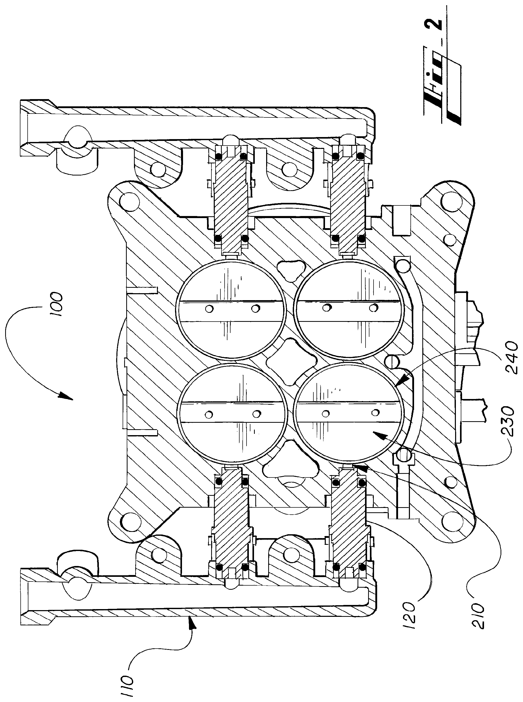
FIG. 2 is cross-section view A-A of the throttle body of FIG. 1.
FIG. 3 is detail view C of the throttle body of FIG. 2.
FIG. 4 is cross-section view B-B of the throttle body of FIG. 1.
FIG. 5 is detail view D of the throttle body of FIG. 4.
FIG. 6 is an isometric bottom view of a throttle body with annular fuel injection according to an embodiment of the invention.
FIG. 7 is detail view E of the throttle body of FIG. 6.
FIG. 8 is an isometric top view of the annular ring element according to an embodiment of the invention.
FIG. 9 is a schematic isometric view showing the fuel injection and air flow according to an embodiment of the invention.
DETAILED DESCRIPTION OF THE PREFERRED EMBODIMENTS
Shown in FIG. 1 is an embodiment of a throttle body 100 having fuel rails 110 aligned horizontally near the bottom surface of the throttle body 100. The fuel rails 110 provide pressurized fuel to the fuel injectors 120, which couple to the throttle body 100 at fuel ports 210 (not shown). In some embodiments the fuel injectors 120 may be aligned horizontally in respect to the throttle body 100. In other embodiments the fuel injectors 120 may be aligned at an angle above or below horizontal in respect to the throttle body 100.
As shown in FIGS. 2-7, each fuel rail 110 may be coupled to one or more fuel injectors 120. Each fuel injector 120 provides fuel through a fuel port 210 into an annular ring 240 positioned in an air intake 220 of the throttle body 100 below the throttle plate 230. The annular ring 240 includes an annular fuel channel 250 for distributing fuel around the annular ring 240 to a plurality of fuel discharge orifices 260 and 270. The plurality of fuel discharge orifices 260 and 270 are configured to atomize and spray the fuel into the air intake 220 from multiple directions.
In some embodiments there may be a larger primary fuel discharge orifice 260 aligned in front of the fuel port 210 along with a plurality of smaller secondary fuel discharge orifices 270 aligned radially around the annular ring 240. In various embodiments the secondary fuel discharge orifices 270 may vary in size and shape as desired. In some embodiments the fuel discharge orifices 260 and 270 may be of circular, ovular, elliptical, and/or polygonal shapes.
In one embodiment the primary fuel discharge orifice 260 may be a 0.25 inch diameter circular orifice. In other embodiments the primary fuel discharge orifice 260 may be a 0.28 to 0.40 inch wide by 0.155 ovular-slot orifice.
In one embodiment the secondary fuel discharge orifices 270 may be 0.047 to 0.100 inch diameter circular orifices. The secondary fuel discharge orifices 270 may be spaced radially around the annular ring 240 at angular separations of 20 to 38 degrees from adjacent orifices.
In a preferred embodiment the annular ring 240 includes a 0.28 inch wide by 0.155 inch ovular-slot high primary fuel discharge orifice 260 and thirteen 0.047 inch diameter circular secondary fuel discharge orifices 270 radially spaced at 20-38 degrees apart from adjacent orifices, and centered on the primary fuel discharge orifice 260, as shown in FIG. 8.
It will be appreciated by those skilled in the art that the primary fuel discharge orifice 260 and the secondary fuel discharge orifices 270 may each be a variety of shapes having close to the same orifice opening areas as those described in the various embodiments of the invention.
During operation, air enters the throttle body 100 through an air intake 220. The flow rate of the air through the air intake 220 is regulated by the throttle plate 230, which may be controlled electromechanically by an ECU (not shown), or mechanically. Pressurized fuel flows through a fuel rail 110 and into a fuel injector 120 controlled by the ECU, which regulates the amount of fuel flowing through the fuel port 210 into the air intake 220. As shown in FIG. 9, the fuel flow exits the fuel port 210 a portion of the fuel enters the air flow 920 in the air intake 220 through the primary fuel discharge orifice 260 as atomized fuel 910. The remainder of the fuel enters the annular fuel channel 250 and exits the annular fuel channel 250 through the secondary fuel discharge orifices 270 and enters the air flow 920 in the air intake 220 as atomized fuel 910.
In preferred embodiments of the invention, 40% to 60% of the fuel enters the air intake 220 though the primary fuel discharge orifice 260.
In various embodiments the throttle body 100 may have one or more air intakes 220 with each air intake 220 including a throttle plate 230, a fuel injector 120, and an annular ring 240.
In some embodiments of the throttle body 100, the annular fuel channel 250 may be a part of the throttle body 100 rather than of part of the annular ring 240. In other embodiments the throttle body 100 and annular ring 240 may include complimentary portions of the annular fuel channel 250.
In some embodiments the inner wall air intake 220 may have a larger diameter equal to the outer diameter of the annular ring 240 near the bottom to accommodate the annular ring 240 so the inner wall of the air intake 220 and the annular ring 240 form a smooth continuous surface to aid air flow.
In some embodiments the annular ring 240 may include an annular groove 410 or other means to aid the installing and/or removing the annular ring 240 from the throttle body 100.
In various embodiments the annular ring 240 may be coupled to the throttle body 100 by one or more of a press fit, threads, a friction fit, mechanical fasteners, adhesives, and welds.
In various embodiments the annular ring 240 may be made of aluminum, steel, cast iron, other metals, plastics, composites, or other materials and/or combinations of materials suitable for throttle body applications.
In the preceding specification, various preferred exemplary embodiments have been described with reference to the accompanying drawings. It will, however, be evident that various modifications and changes may be made thereto, and additional exemplary embodiments may be implemented, without departing from the broader scope of the invention as set forth in the claims that follow. The specification and drawings are accordingly to be regarded in an illustrative rather than restrictive sense.
* * * * *
D00000
D00001
D00002
D00003
D00004
D00005
D00006
D00007
D00008
XML
uspto.report is an independent third-party trademark research tool that is not affiliated, endorsed, or sponsored by the United States Patent and Trademark Office (USPTO) or any other governmental organization. The information provided by uspto.report is based on publicly available data at the time of writing and is intended for informational purposes only.
While we strive to provide accurate and up-to-date information, we do not guarantee the accuracy, completeness, reliability, or suitability of the information displayed on this site. The use of this site is at your own risk. Any reliance you place on such information is therefore strictly at your own risk.
All official trademark data, including owner information, should be verified by visiting the official USPTO website at www.uspto.gov. This site is not intended to replace professional legal advice and should not be used as a substitute for consulting with a legal professional who is knowledgeable about trademark law.