Wheel machining tool
Liu , et al. Feb
U.S. patent number 10,569,335 [Application Number 16/032,488] was granted by the patent office on 2020-02-25 for wheel machining tool. This patent grant is currently assigned to CITIC DICASTAL CO., LTD. The grantee listed for this patent is CITIC Dicastal CO., LTD. Invention is credited to Jiandong Guo, Xiaoguang Huang, Huiying Liu, Minghua Liu, Weidong Liu, Xiao Liu, Yuexin Lu, Zhiyuan Yu, Ruixiao Zhou, Yingjun Zhou.

| United States Patent | 10,569,335 |
| Liu , et al. | February 25, 2020 |
Wheel machining tool
Abstract
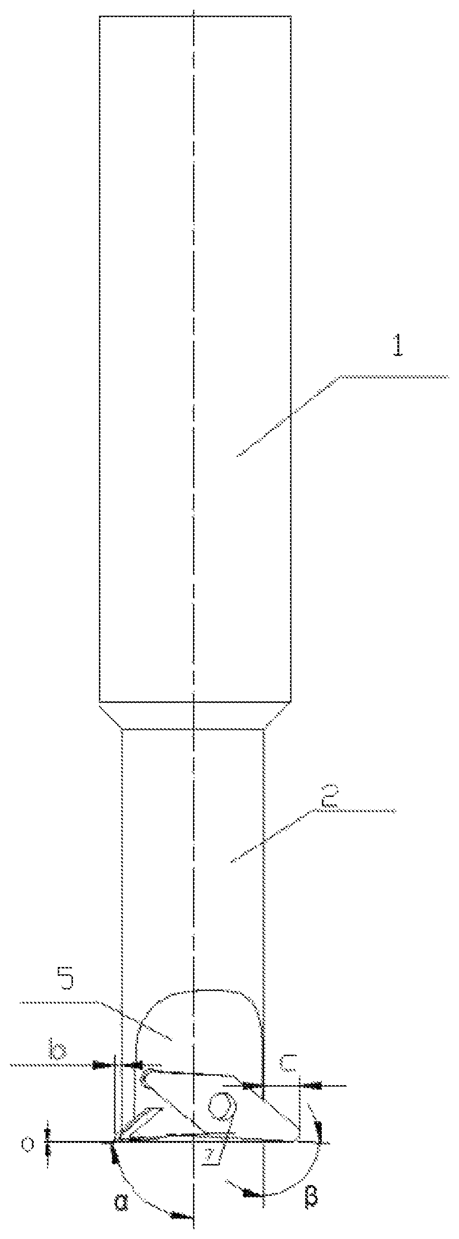
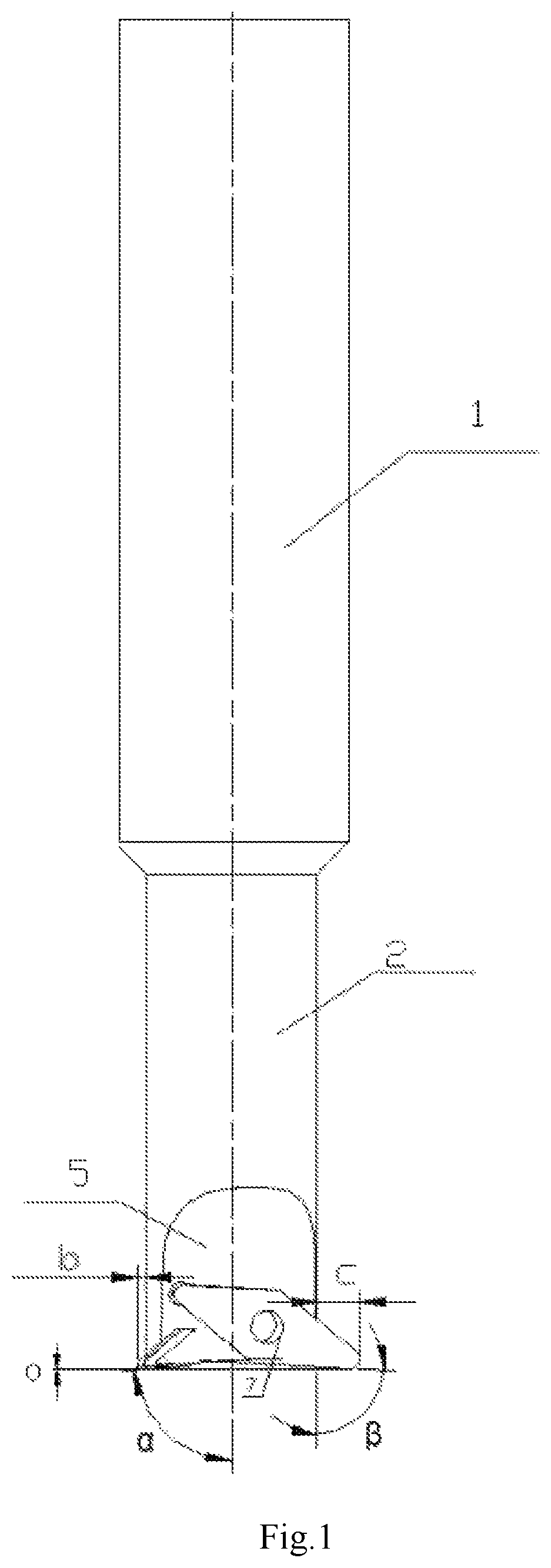
The invention discloses a wheel machining tool. A rough turning tool and a finish turning tool are respectively arranged on two sides of a tool head, the primary declination angle .beta. of the rough turning tool is set to 90.degree. to 120.degree., and the primary declination angle .alpha. of the finish turning tool is set to 85.degree. to 95.degree.; the axial height difference between the rough turning tool and the finish turning tool is set to 0.2-0.5 mm; the distance c between the rough turning tool and the tool head is set to 5-8 mm, and the distance b between the finish turning tool and the tool head is set to 3-5 mm. The rake angle .delta. of the rough turning tool is set to 12.degree.-15.degree., the rake angle .gamma. of the finish turning tool is set to 14.degree.-17.degree..
| Inventors: | Liu; Minghua (Qinhuangdao, CN), Zhou; Yingjun (Qinhuangdao, CN), Liu; Weidong (Qinhuangdao, CN), Liu; Xiao (Qinhuangdao, CN), Huang; Xiaoguang (Qinhuangdao, CN), Guo; Jiandong (Qinhuangdao, CN), Liu; Huiying (Qinhuangdao, CN), Lu; Yuexin (Qinhuangdao, CN), Yu; Zhiyuan (Qinhuangdao, CN), Zhou; Ruixiao (Qinhuangdao, CN) | ||||||||||
|---|---|---|---|---|---|---|---|---|---|---|---|
| Applicant: |
|
||||||||||
| Assignee: | CITIC DICASTAL CO., LTD
(Qinhuangdao Hebei, CN) |
||||||||||
| Family ID: | 62808602 | ||||||||||
| Appl. No.: | 16/032,488 | ||||||||||
| Filed: | July 11, 2018 |
Prior Publication Data
| Document Identifier | Publication Date | |
|---|---|---|
| US 20190262905 A1 | Aug 29, 2019 | |
Foreign Application Priority Data
| Feb 24, 2018 [CN] | 2018 1 01563149 | |||
| Current U.S. Class: | 1/1 |
| Current CPC Class: | B23B 27/145 (20130101); B23B 29/24 (20130101); B23B 5/02 (20130101); B23B 2220/445 (20130101); B23B 2215/08 (20130101); B23B 2200/28 (20130101); B23B 2226/315 (20130101); B23B 2200/201 (20130101) |
| Current International Class: | B23B 27/00 (20060101); B23B 5/02 (20060101); B23B 27/14 (20060101); B23B 29/24 (20060101) |
References Cited [Referenced By]
U.S. Patent Documents
| 1460029 | June 1923 | Mattson |
| 2630725 | March 1953 | Black |
| 3759625 | September 1973 | Iversen |
| 4105360 | August 1978 | Keller |
| 4586855 | May 1986 | Rawle |
| 6913428 | July 2005 | Kress |
| 2009/0257834 | October 2009 | Lysobey |
| 2011/0222979 | September 2011 | Stadelmann |
| 2012/0230790 | September 2012 | Uno |
| 2014/0161544 | June 2014 | Morandeau, Sr. |
| 3008008 | Sep 1981 | DE | |||
| 102013014761 | Mar 2015 | DE | |||
| 2050529 | Apr 2009 | EP | |||
| 2924631 | Jun 2009 | FR | |||
| 58217212 | Dec 1983 | JP | |||
| 02292108 | Dec 1990 | JP | |||
| 08155723 | Jun 1996 | JP | |||
| 10277830 | Oct 1998 | JP | |||
| 11262812 | Sep 1999 | JP | |||
| 2001150219 | Jun 2001 | JP | |||
Other References
|
JP-11262812-A Machine Translation, pp. 4-7 (Year: 2019). cited by examiner . JP-08155723-A Machine Translation, pp. 6-11 (Year: 2019). cited by examiner. |
Primary Examiner: Ramos; Nicole N
Attorney, Agent or Firm: Calfee, Halter & Griswold LLP
Claims
What is claimed is:
1. A wheel machining tool, comprising a tool shank, a tool head, a rough turning flute, a finish turning flute and fastening screws, wherein a rough turning tool and a finish turning tool are respectively arranged on two sides of the tool head, a primary declination angle .beta. of the rough turning tool is set to 90.degree. to 120.degree., and a primary declination angle .alpha. of the finish turning tool is set to 85.degree. to 95.degree.; a axial height difference between the rough turning tool and the finish turning tool is set to 0.2 mm to 0.5 mm; a distance c between the rough turning tool and the tool head is set to 5 mm to 8 mm, and a distance b between the finish turning tool and the tool head is set to 3 mm to 5 mm; the rough turning flute adopts a smooth transition surface from a plane of the rough turning tool to the tool head, and the finish turning flute also adopts a smooth transition surface from a plane of the finish turning tool to the tool head, each transition arc of the smooth transition surface is not less than 8 mm, a rake angle .delta. of the rough turning tool is set to 12.degree. to 15.degree., a rake angle .gamma. of the finish turning tool is set to 14.degree. to 17.degree., and a cutting edge of a rough turning blade of the rough turning tool and a cutting edge of a finish turning blade of the finish turning tool are distributed clockwise.
Description
CROSS-REFERENCE TO RELATED APPLICATIONS
This application claims priority to Chinese Patent Application No. 201810156314.9 filed on Feb. 24, 2018, which is hereby incorporated by reference in its entirety.
TECHNICAL FIELD
The present application relates to a machining tool, specifically to an efficient tool for machining wheels.
BACKGROUND ART
During machining, in order to better remove the blank allowance and ensure the final dimensional accuracy of a product, rough turning and finish turning are established in the general machining process; the wheel is also machined by rough turning and finish turning, a blade having a large corner radius is adopted in rough turning to improve the rigidity and the stability of the tool, while a blade having a small corner radius is adopted in finish turning to ensure the surface quality and the dimensional accuracy; in the exiting wheel machining tools, the rough turning tool and the finish turning tool are respectively installed on a turret as two independent parts; after the rough turning, the turret will return to the origin to switch the tool, and then the finish turning is performed; and on the premise of unchanged machining parameters, how to ensure the machining quality and reduce the machining time becomes an urgent need.
SUMMARY OF THE INVENTION
The aim of the present application is to provide an efficient tool integrating rough turning and finish turning.
To achieve the above aim, the technical solution of the present application is: a wheel machining tool, including a tool shank, a tool head, a rough turning tool, a finish turning tool, a rough turning flute, a finish turning flute and fastening screws.
The rough turning blade of the rough turning tool is a hard alloy rhombic blade having a point radius of R3, and the finish turning blade of the rough turning tool is a polycrystalline diamond rhombic blade having a point radius of R0.8. The rough turning blade and the finish turning blade are symmetrically distributed along the axis of the tool shank, and the rough turning tool and the finish turning tool are respectively fixed on the tool head by the fastening screws. The primary declination angle of the rough turning tool is .beta. from 90.degree. to 120.degree., and the primary declination angle of the finish turning tool is .alpha. from 85.degree. to 95.degree..
In order to ensure that the rough turning tool and the finish turning tool do not interfere in machining the end face perpendicular to the axis of the tool shank, a height difference a of 0.2 mm to 0.5 mm is set between the rough turning tool and the finish turning tool in the direction parallel to the axis of the tool shank; and considering that the engagement of the cutting edge of the rough turning tool is greater than that of the finish turning tool, a distance c of 5 mm to 8 mm is set between the rough turning tool and the tool head, and a distance b of 3 mm to 5 mm is set between the finish turning tool and the tool head.
In order to ensure smooth chip discharge during machining, both the rough turning flute and the finish turning flute adopt a smooth transition surface from the plane of the tools to the tool head, and the transition arc is not less than 8 mm.
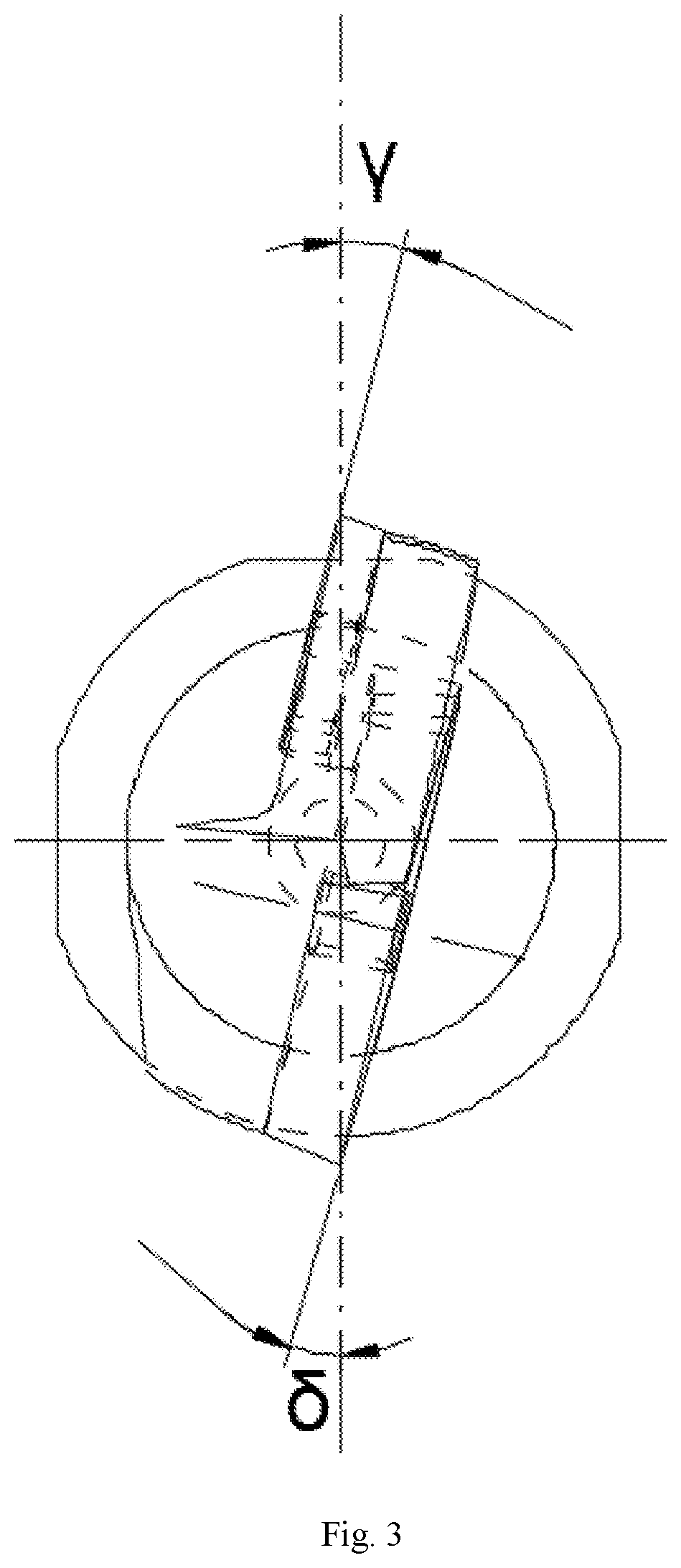
In order to ensure that the cutting edges of the finish turning tool and the rough turning tool are located on the same plane passing through the central axis of the tool shank, the rake angle of the rough turning tool is set to .delta. between 12.degree. and 15.degree., and the rake angle of the finish turning tool is set to .gamma. between 14.degree. and 17.degree.. The cutting edges of the rough turning blade and the finish turning blade are distributed clockwise, thereby avoiding to-and-fro and positive-negative switchover of the main shaft during machining.
In the present application, the rough turning tool and the finish turning tool are fixed on the same tool head to realize a machining process including a rough turning step and a finish turning step on the same tool at the same time. Particularly when a hole is machined, due to the rotation characteristic of a hole machining part, two machining functions of left offset and right offset of the tool can be directly realized under the condition that the tool does not return to the origin, so that the time for changing the rough or finish turning tool is reduced, better matching of rough turning and finish turning quantities can be realized, the tool wear caused by mismatch of the machining quantities is reduced and the service life of the tool is prolonged. Because the rough turning function and the finish turning function are realized at one tool position on the turret, the rough turning tool and the finish turning tool can be regarded to use two tool compensations during actual machining, or the same tool can also be regarded to use one tool compensation, so that the diversity of tool compensation adjusted in real time increases. The present application not only can be applied in wheel machining, but also has a wide application prospect in machining of more rotating members, and at the same time, has the characteristics of simple manufacture and low cost.
BRIEF DESCRIPTION OF DRAWINGS
FIG. 1 is a front view of a wheel machining tool.
FIG. 2 is a right view of the wheel machining tool.
FIG. 3 is an upward view of the wheel machining tool, in FIG. 3, the dash dot line is where a plane of the rough turning tool or a plane of the finish turning tool is located.
In which, 1--tool shank, 2--tool head, 3--rough turning tool, 4--finish turning tool, 5--rough turning flute, 6--finish turning flute, 7--fastening screw.
DETAILED DESCRIPTION OF THE INVENTION
Specific details and working conditions of a device provided by the present application will be given below in combination with the accompanying drawings.
Embodiment 1: According to a wheel machining tool, a rough turning tool 3 and a finish turning tool 4 are arranged on two sides of a tool head 2 respectively and embedded into a tool groove in the tool head 2 through fastening screws 7. The primary declination angle .beta. of the rough turning tool 3 is 100.degree., and the primary declination angle .alpha. of the finish turning tool 4 is 90.degree.. The height difference a between the rough turning tool 3 and the finish turning tool 4 in the direction parallel to the axis of a tool shank 1 is 0.4 mm, the distance c between the rough turning tool 3 and the tool head 2 is 6 mm, and the distance b between the finish turning tool 4 and the tool head 2 is 4 mm. The rake angle .delta. of the rough turning tool 3 is set to 13.degree., the rake angle .gamma. of the finish turning tool 4 is set to 15.degree., and the cutting edges of blades of the rough turning tool 3 and the finish turning tool 4 are distributed clockwise.
According to the present application, the machining tracks originally completed using a rough turning tool and a finish turning tool are integrated on one tool, and the tool can simultaneously complete rough turning and finish turning by reasonably distributing the angles and the relative position relation of the rough turning tool 3 and the finish turning tool 4 for the actual machined blank, thereby saving the time when the turret returns to the origin, reducing the tool change time, saving the quick positioning time for one tool at the same time and achieving higher machining efficiency.
The foregoing descriptions of specific exemplary embodiments of the present invention have been presented for purposes of illustration and description. They are not intended to be exhaustive or to limit the invention to the precise forms disclosed, and obviously many modifications and variations are possible in light of the above teachings. The exemplary embodiments were chosen and described in order to explain certain principles of the invention and their practical application, to thereby enable others skilled in the art to make and utilize various exemplary embodiments of the present invention, as well as various alternatives and modifications thereof. It is intended that the scope of the invention be defined by the claims appended hereto and their equivalents.
* * * * *
D00000
D00001
D00002
D00003
XML
uspto.report is an independent third-party trademark research tool that is not affiliated, endorsed, or sponsored by the United States Patent and Trademark Office (USPTO) or any other governmental organization. The information provided by uspto.report is based on publicly available data at the time of writing and is intended for informational purposes only.
While we strive to provide accurate and up-to-date information, we do not guarantee the accuracy, completeness, reliability, or suitability of the information displayed on this site. The use of this site is at your own risk. Any reliance you place on such information is therefore strictly at your own risk.
All official trademark data, including owner information, should be verified by visiting the official USPTO website at www.uspto.gov. This site is not intended to replace professional legal advice and should not be used as a substitute for consulting with a legal professional who is knowledgeable about trademark law.