Mechanical teleoperated device for remote manipulation
Beira Feb
U.S. patent number 10,568,709 [Application Number 15/564,193] was granted by the patent office on 2020-02-25 for mechanical teleoperated device for remote manipulation. This patent grant is currently assigned to Distalmotion SA. The grantee listed for this patent is DistalMotion SA. Invention is credited to Ricardo Daniel Rita Beira.


View All Diagrams
| United States Patent | 10,568,709 |
| Beira | February 25, 2020 |
Mechanical teleoperated device for remote manipulation
Abstract
A mechanical teleoperated device for remote manipulation is provided that is primarily intended for use in minimally invasive surgery. The device generally comprises a slave unit having a number of slave links interconnected by a plurality of slave joints, an end-effector connected to the distal end of the slave unit, a master unit having a corresponding number of master links interconnected by a plurality of master joints, and a handle connected to the distal end of the master unit for operating the mechanical teleoperated device. The device further comprises mechanical transmission means arranged to kinematically connect the slave unit with the master unit such that the movement applied on each master joint of the master unit is reproduced by the corresponding slave joint of the slave unit. In addition, the mechanical teleoperated device comprises improved kinematics and an improved arrangement of mechanical constraints, allowing for improved positioning of the device over a patient, increased workspace inside the patient and ease of workflow in an operating room.
| Inventors: | Beira; Ricardo Daniel Rita (Lausanne, CH) | ||||||||||
|---|---|---|---|---|---|---|---|---|---|---|---|
| Applicant: |
|
||||||||||
| Assignee: | Distalmotion SA (Epalinges,
CH) |
||||||||||
| Family ID: | 56296858 | ||||||||||
| Appl. No.: | 15/564,193 | ||||||||||
| Filed: | April 11, 2016 | ||||||||||
| PCT Filed: | April 11, 2016 | ||||||||||
| PCT No.: | PCT/IB2016/000543 | ||||||||||
| 371(c)(1),(2),(4) Date: | October 03, 2017 | ||||||||||
| PCT Pub. No.: | WO2016/162752 | ||||||||||
| PCT Pub. Date: | October 13, 2016 |
Prior Publication Data
| Document Identifier | Publication Date | |
|---|---|---|
| US 20180125592 A1 | May 10, 2018 | |
Related U.S. Patent Documents
| Application Number | Filing Date | Patent Number | Issue Date | ||
|---|---|---|---|---|---|
| 62145452 | Apr 9, 2015 | ||||
| Current U.S. Class: | 1/1 |
| Current CPC Class: | B25J 3/02 (20130101); B25J 18/007 (20130101); A61B 34/37 (20160201); A61B 34/70 (20160201); A61B 34/71 (20160201); A61B 34/30 (20160201); A61B 34/77 (20160201); A61B 17/00234 (20130101); A61B 2034/715 (20160201); A61B 2090/506 (20160201) |
| Current International Class: | A61B 34/37 (20160101); A61B 17/00 (20060101); B25J 3/02 (20060101); B25J 18/00 (20060101); A61B 34/00 (20160101); A61B 90/50 (20160101) |
| Field of Search: | ;700/3,12 |
References Cited [Referenced By]
U.S. Patent Documents
| 2764301 | September 1956 | Goertz et al. |
| 2771199 | November 1956 | Jelatis |
| 2774488 | December 1956 | Goertz |
| 2846084 | August 1958 | Goertz et al. |
| 3065863 | November 1962 | Saunders, Jr. |
| 3095096 | June 1963 | Chesley |
| 3212651 | October 1965 | Specht et al. |
| 3261480 | July 1966 | Haaker et al. |
| 3297172 | January 1967 | Haaker et al. |
| 3391801 | July 1968 | Haaker |
| 3425569 | February 1969 | Haaker |
| 4221516 | September 1980 | Haaker et al. |
| 4756655 | July 1988 | Jameson |
| 5147357 | September 1992 | Rose et al. |
| 5176352 | January 1993 | Braun |
| 5207114 | May 1993 | Salisbury et al. |
| 5209747 | May 1993 | Knoepfler |
| 5304203 | April 1994 | El-Mallawany et al. |
| 5308358 | May 1994 | Bond et al. |
| 5330502 | July 1994 | Hassler et al. |
| 5368606 | November 1994 | Marlow et al. |
| 5383888 | January 1995 | Zvenyatsky et al. |
| 5484435 | January 1996 | Fleenor et al. |
| 5599151 | February 1997 | Daum et al. |
| 5603723 | February 1997 | Aranyi et al. |
| 5631973 | May 1997 | Green |
| 5649956 | July 1997 | Jensen et al. |
| 5710870 | January 1998 | Ohm et al. |
| 5716352 | February 1998 | Viola et al. |
| 5735874 | April 1998 | Measamer et al. |
| 5784542 | July 1998 | Ohm et al. |
| 5797900 | August 1998 | Madhani et al. |
| 5810716 | September 1998 | Mukherjee et al. |
| 5810805 | September 1998 | Sutcu et al. |
| 5828813 | October 1998 | Ohm |
| 5908436 | June 1999 | Cuschieri et al. |
| 5931832 | August 1999 | Jensen |
| 5951587 | September 1999 | Qureshi et al. |
| 5976122 | November 1999 | Madhani et al. |
| 6026701 | February 2000 | Reboulet |
| 6132368 | October 2000 | Cooper |
| 6197017 | March 2001 | Brock et al. |
| 6206903 | March 2001 | Ramans |
| 6233504 | May 2001 | Das et al. |
| 6281651 | August 2001 | Haanpaa et al. |
| 6312435 | November 2001 | Wallace et al. |
| 6331181 | December 2001 | Tierney et al. |
| 6358249 | March 2002 | Chen et al. |
| 6361534 | March 2002 | Chen et al. |
| 6364879 | April 2002 | Chen et al. |
| 6371952 | April 2002 | Madhani et al. |
| 6394998 | May 2002 | Wallace et al. |
| 6435794 | August 2002 | Springer |
| 6459926 | October 2002 | Nowlin et al. |
| 6491701 | December 2002 | Tierney et al. |
| 6554844 | April 2003 | Lee et al. |
| 6587750 | July 2003 | Gerbi et al. |
| 6594552 | July 2003 | Nowlin et al. |
| 6671581 | December 2003 | Niemeyer et al. |
| 6699177 | March 2004 | Wang et al. |
| 6786896 | September 2004 | Madhani et al. |
| 6788999 | September 2004 | Green |
| 6840938 | January 2005 | Morley et al. |
| 6850817 | February 2005 | Green |
| 6852107 | February 2005 | Wang et al. |
| 6879880 | April 2005 | Nowlin et al. |
| 6902560 | June 2005 | Morley et al. |
| 6913613 | July 2005 | Schwarz et al. |
| 6951535 | October 2005 | Ghodoussi et al. |
| 6991627 | January 2006 | Madhani et al. |
| 6994708 | February 2006 | Manzo |
| 7048745 | May 2006 | Tierney et al. |
| 7083571 | August 2006 | Wang et al. |
| 7090637 | August 2006 | Danitz et al. |
| 7101363 | September 2006 | Nishizawa et al. |
| 7204836 | April 2007 | Wagner et al. |
| 7232440 | June 2007 | Dumbauld et al. |
| 7241289 | July 2007 | Braun |
| 7306597 | December 2007 | Manzo |
| 7316681 | January 2008 | Madhani et al. |
| 7338513 | March 2008 | Lee et al. |
| 7364582 | April 2008 | Lee |
| 7373219 | May 2008 | Nowlin et al. |
| 7398707 | July 2008 | Morley et al. |
| 7481824 | January 2009 | Boudreaux et al. |
| 7549998 | June 2009 | Braun |
| 7594912 | September 2009 | Cooper et al. |
| 7608039 | October 2009 | Todd |
| 7615002 | November 2009 | Rothweiler et al. |
| 7615067 | November 2009 | Lee et al. |
| 7674255 | March 2010 | Braun |
| 7699855 | April 2010 | Anderson et al. |
| 7756036 | July 2010 | Druke et al. |
| 7819894 | October 2010 | Mitsuishi et al. |
| 7824401 | November 2010 | Manzo et al. |
| 7828798 | November 2010 | Buysse et al. |
| 7833156 | November 2010 | Williams et al. |
| 7890211 | February 2011 | Green |
| 7914521 | March 2011 | Wang et al. |
| 7976458 | July 2011 | Stefanchik et al. |
| 8048084 | November 2011 | Schneid |
| 8105320 | January 2012 | Manzo |
| 8114017 | February 2012 | Bacher |
| 8137263 | March 2012 | Marescaux et al. |
| 8142447 | March 2012 | Cooper et al. |
| 8224485 | July 2012 | Unsworth |
| 8246617 | August 2012 | Welt et al. |
| 8267958 | September 2012 | Braun |
| 8287469 | October 2012 | Stefanchik et al. |
| 8292889 | October 2012 | Cunningham et al. |
| 8306656 | November 2012 | Schaible et al. |
| 8308738 | November 2012 | Nobis et al. |
| 8332072 | December 2012 | Schaible et al. |
| 8336751 | December 2012 | Scirica |
| 8347754 | January 2013 | Veltri et al. |
| 8353898 | January 2013 | Lutze et al. |
| 8357161 | January 2013 | Mueller |
| 8382742 | February 2013 | Hermann et al. |
| 8388516 | March 2013 | Sholev |
| 8403832 | March 2013 | Cunningham et al. |
| 8414475 | April 2013 | Sholev |
| 8418904 | April 2013 | Wenchell et al. |
| 8423186 | April 2013 | Itkowitz et al. |
| 8435171 | May 2013 | Sholev |
| 8496152 | July 2013 | Viola |
| 8518024 | August 2013 | Williams et al. |
| 8523900 | September 2013 | Jinno et al. |
| 8540748 | September 2013 | Murphy et al. |
| 8562592 | October 2013 | Conlon et al. |
| 8568444 | October 2013 | Cunningham |
| 8579176 | November 2013 | Smith et al. |
| 8591397 | November 2013 | Berkelman et al. |
| 8602287 | December 2013 | Yates et al. |
| 8603077 | December 2013 | Cooper et al. |
| 8617203 | December 2013 | Stefanchik et al. |
| 8663270 | March 2014 | Donnigan et al. |
| 8668689 | March 2014 | Dumbauld et al. |
| 8668702 | March 2014 | Awtar et al. |
| 8690755 | April 2014 | Sholev |
| 8696666 | April 2014 | Sanai et al. |
| 8709000 | April 2014 | Madhani et al. |
| 8761930 | June 2014 | Nixon |
| 8768509 | July 2014 | Unsworth |
| 8792688 | July 2014 | Unsworth |
| 8801752 | August 2014 | Fortier et al. |
| 8816628 | August 2014 | Nowlin et al. |
| 8818560 | August 2014 | Kishi |
| 8821480 | September 2014 | Burbank |
| 8827135 | September 2014 | Amid et al. |
| 8828046 | September 2014 | Stefanchik et al. |
| 8845517 | September 2014 | Russo |
| 8845622 | September 2014 | Paik et al. |
| 8870049 | October 2014 | Amid et al. |
| 8870867 | October 2014 | Walberg et al. |
| 8887979 | November 2014 | Mastri et al. |
| 8894674 | November 2014 | Balanev et al. |
| 8919348 | December 2014 | Williams et al. |
| 8930027 | January 2015 | Schaible et al. |
| 8945098 | February 2015 | Seibold et al. |
| 8961499 | February 2015 | Paik et al. |
| 8961514 | February 2015 | Garrison |
| 8968187 | March 2015 | Kleyman et al. |
| 8989844 | March 2015 | Cinquin et al. |
| 8992564 | March 2015 | Jaspers |
| 9023015 | May 2015 | Penna |
| 9033998 | May 2015 | Schaible et al. |
| 9044238 | June 2015 | Orszulak |
| 9084606 | July 2015 | Greep |
| 9113861 | August 2015 | Martin et al. |
| 9149339 | October 2015 | Unsworth |
| 9204939 | December 2015 | Frimer et al. |
| 9295379 | March 2016 | Sholev |
| 9307894 | April 2016 | Von Grunberg et al. |
| 9333040 | May 2016 | Shellenberger et al. |
| 9345545 | May 2016 | Shellenberger et al. |
| 9360934 | June 2016 | Ruiz Morales et al. |
| 9474580 | October 2016 | Hannaford et al. |
| 9480531 | November 2016 | Von Grunberg |
| 9492240 | November 2016 | Itkowitz et al. |
| 9504456 | November 2016 | Frimer et al. |
| 9603672 | March 2017 | Shellenberger et al. |
| 9669542 | June 2017 | Karguth et al. |
| 9696700 | July 2017 | Beira et al. |
| 9757204 | September 2017 | Frimer et al. |
| 9757206 | September 2017 | Frimer et al. |
| 9795282 | October 2017 | Sholev et al. |
| 9795454 | October 2017 | Seeber et al. |
| 9877794 | January 2018 | Csiky |
| D816243 | April 2018 | Barber |
| 9937013 | April 2018 | Frimer et al. |
| 9943372 | April 2018 | Sholev et al. |
| 10028792 | July 2018 | Frimer et al. |
| 10039609 | August 2018 | Frimer et al. |
| 10052157 | August 2018 | Frimer et al. |
| 10064691 | September 2018 | Frimer et al. |
| 10071488 | September 2018 | Robinson et al. |
| 10092164 | October 2018 | Sholev et al. |
| 10092359 | October 2018 | Beira et al. |
| 10092365 | October 2018 | Seeber |
| 10136956 | November 2018 | Seeber |
| 10201392 | February 2019 | Frimer et al. |
| 10265129 | April 2019 | Beira |
| 10325072 | June 2019 | Beira et al. |
| 2002/0040217 | April 2002 | Jinno |
| 2002/0049367 | April 2002 | Irion et al. |
| 2002/0072736 | June 2002 | Tierney et al. |
| 2003/0155747 | August 2003 | Bridges |
| 2003/0208186 | November 2003 | Moreyra |
| 2004/0049205 | March 2004 | Lee et al. |
| 2004/0116906 | June 2004 | Lipow |
| 2004/0236316 | November 2004 | Danitz et al. |
| 2004/0253079 | December 2004 | Sanchez |
| 2005/0096502 | May 2005 | Khalili |
| 2005/0204851 | September 2005 | Morley et al. |
| 2005/0240078 | October 2005 | Kwon et al. |
| 2006/0043698 | March 2006 | Bridges |
| 2006/0178559 | August 2006 | Kumar et al. |
| 2006/0183975 | August 2006 | Saadat et al. |
| 2006/0219065 | October 2006 | Jinno et al. |
| 2006/0235436 | October 2006 | Anderson et al. |
| 2006/0253109 | November 2006 | Chu |
| 2007/0088340 | April 2007 | Brock et al. |
| 2007/0137371 | June 2007 | Devengenzo |
| 2007/0156123 | July 2007 | Moll et al. |
| 2007/0208375 | September 2007 | Nishizawa et al. |
| 2007/0299387 | December 2007 | Williams et al. |
| 2008/0039255 | February 2008 | Jinno et al. |
| 2008/0046122 | February 2008 | Manzo et al. |
| 2008/0058776 | March 2008 | Jo et al. |
| 2008/0071208 | March 2008 | Voegele et al. |
| 2008/0103492 | May 2008 | Morley et al. |
| 2008/0177285 | July 2008 | Brock et al. |
| 2008/0243106 | October 2008 | Coe et al. |
| 2008/0314181 | December 2008 | Schena |
| 2009/0036902 | February 2009 | Dimaio et al. |
| 2009/0198253 | August 2009 | Omori |
| 2009/0216248 | August 2009 | Uenohara et al. |
| 2009/0216249 | August 2009 | Jinno et al. |
| 2009/0247821 | October 2009 | Rogers |
| 2009/0248039 | October 2009 | Cooper et al. |
| 2009/0299141 | December 2009 | Downey et al. |
| 2010/0004508 | January 2010 | Naito et al. |
| 2010/0011900 | January 2010 | Burbank |
| 2010/0023025 | January 2010 | Zeiner et al. |
| 2010/0094130 | April 2010 | Ninomiya et al. |
| 2010/0121347 | May 2010 | Jaspers |
| 2010/0160929 | June 2010 | Rogers et al. |
| 2010/0160940 | June 2010 | Lutze et al. |
| 2010/0170519 | July 2010 | Romo et al. |
| 2010/0225209 | September 2010 | Goldberg et al. |
| 2010/0305595 | December 2010 | Hermann |
| 2010/0318099 | December 2010 | Itkowitz et al. |
| 2010/0318101 | December 2010 | Choi |
| 2010/0331859 | December 2010 | Omori |
| 2011/0087236 | April 2011 | Stokes et al. |
| 2011/0087238 | April 2011 | Wang et al. |
| 2011/0213346 | September 2011 | Morley et al. |
| 2011/0230867 | September 2011 | Hirschfeld et al. |
| 2011/0275901 | November 2011 | Shelton, IV |
| 2011/0276084 | November 2011 | Shelton, IV |
| 2011/0290854 | December 2011 | Timm et al. |
| 2011/0301419 | December 2011 | Craft et al. |
| 2012/0027762 | February 2012 | Schofield |
| 2012/0031114 | February 2012 | Mueller et al. |
| 2012/0049623 | March 2012 | Nakayama |
| 2012/0095298 | April 2012 | Stefanchik et al. |
| 2012/0116163 | May 2012 | Lutze et al. |
| 2012/0132018 | May 2012 | Tang et al. |
| 2012/0143173 | June 2012 | Steege et al. |
| 2012/0158014 | June 2012 | Stefanchik et al. |
| 2012/0191245 | July 2012 | Fudaba et al. |
| 2012/0209292 | August 2012 | Devengenzo et al. |
| 2012/0253326 | October 2012 | Kleyman |
| 2012/0277762 | November 2012 | Lathrop et al. |
| 2012/0283745 | November 2012 | Goldberg et al. |
| 2012/0289973 | November 2012 | Prisco et al. |
| 2012/0289974 | November 2012 | Rogers et al. |
| 2012/0296341 | November 2012 | Seibold et al. |
| 2013/0123805 | May 2013 | Park et al. |
| 2013/0144274 | June 2013 | Stefanchik et al. |
| 2013/0172713 | July 2013 | Kirschenman |
| 2013/0245643 | September 2013 | Woodard et al. |
| 2013/0245647 | September 2013 | Martin et al. |
| 2013/0282027 | October 2013 | Woodard et al. |
| 2013/0304083 | November 2013 | Kaercher et al. |
| 2013/0304084 | November 2013 | Beira |
| 2014/0005681 | January 2014 | Gee et al. |
| 2014/0018447 | January 2014 | McGovern et al. |
| 2014/0018780 | January 2014 | Hirscheld |
| 2014/0076088 | March 2014 | Berkelman et al. |
| 2014/0114481 | April 2014 | Ogawa et al. |
| 2014/0142595 | May 2014 | Awtar et al. |
| 2014/0166023 | June 2014 | Kishi |
| 2014/0180308 | June 2014 | Von Grunberg |
| 2014/0188091 | July 2014 | Vidal et al. |
| 2014/0188159 | July 2014 | Steege |
| 2014/0195010 | July 2014 | Beira |
| 2014/0200561 | July 2014 | Ingmanson et al. |
| 2014/0207150 | July 2014 | Rosa et al. |
| 2014/0230595 | August 2014 | Butt et al. |
| 2014/0249546 | September 2014 | Shvartsberg et al. |
| 2014/0263541 | September 2014 | Leimbach et al. |
| 2014/0263553 | September 2014 | Leimbach et al. |
| 2014/0276950 | September 2014 | Smaby |
| 2014/0276951 | September 2014 | Hourtash |
| 2014/0276956 | September 2014 | Crainich et al. |
| 2014/0350570 | November 2014 | Lee |
| 2015/0057499 | February 2015 | Erden et al. |
| 2015/0057702 | February 2015 | Edmondson et al. |
| 2015/0060517 | March 2015 | Williams |
| 2015/0066018 | March 2015 | Doll et al. |
| 2015/0105821 | April 2015 | Ward et al. |
| 2015/0113933 | April 2015 | Markt |
| 2015/0142018 | May 2015 | Sniffin et al. |
| 2015/0150575 | June 2015 | Hartoumbekis et al. |
| 2015/0230869 | August 2015 | Shim et al. |
| 2015/0250547 | September 2015 | Fukushima et al. |
| 2015/0265355 | September 2015 | Prestel et al. |
| 2016/0022365 | January 2016 | Jensen et al. |
| 2016/0051274 | February 2016 | Howell et al. |
| 2016/0151115 | June 2016 | Karguth et al. |
| 2016/0346053 | December 2016 | Beira |
| 2016/0374766 | December 2016 | Schuh |
| 2017/0245954 | August 2017 | Beira |
| 2017/0273749 | September 2017 | Grover et al. |
| 2017/0308667 | October 2017 | Beira et al. |
| 2017/0360522 | December 2017 | Beira |
| 2017/0367778 | December 2017 | Beira |
| 2018/0000472 | January 2018 | Beira |
| 2018/0000544 | January 2018 | Beira |
| 2018/0000550 | January 2018 | Beira |
| 2018/0028269 | February 2018 | Morel et al. |
| 2018/0055583 | March 2018 | Schuh et al. |
| 2018/0125519 | May 2018 | Beira et al. |
| 2018/0125592 | May 2018 | Beira |
| 2018/0242991 | August 2018 | Beira |
| 2018/0353252 | December 2018 | Chassot et al. |
| 2018/0360548 | December 2018 | Marshall et al. |
| 101584594 | Nov 2009 | CN | |||
| 101637402 | Feb 2010 | CN | |||
| 101732093 | Jun 2010 | CN | |||
| 103717355 | Apr 2014 | CN | |||
| 43 03 311 | Aug 1994 | DE | |||
| 19652792 | May 1999 | DE | |||
| 10314827 | Apr 2004 | DE | |||
| 10314828 | Jul 2004 | DE | |||
| 10 2012 222 755 | Jun 2014 | DE | |||
| 10 2014 205 036 | Sep 2015 | DE | |||
| 10 2014 205 159 | Sep 2015 | DE | |||
| 0 595 291 | May 1994 | EP | |||
| 0 621 009 | Oct 1994 | EP | |||
| 0 677 275 | Oct 1995 | EP | |||
| 0 776 739 | Jun 1997 | EP | |||
| 1 254 642 | Nov 2002 | EP | |||
| 1 279 371 | Dec 2004 | EP | |||
| 1 886 630 | Feb 2008 | EP | |||
| 1 889 579 | Feb 2008 | EP | |||
| 2 058 090 | May 2009 | EP | |||
| 1 977 677 | Aug 2009 | EP | |||
| 2 095 778 | Sep 2009 | EP | |||
| 1 889 583 | Apr 2011 | EP | |||
| 2 377 477 | May 2012 | EP | |||
| 2 473 119 | Jul 2012 | EP | |||
| 2 305 144 | Oct 2012 | EP | |||
| 2 044 893 | Jul 2013 | EP | |||
| 2 653 110 | Oct 2013 | EP | |||
| 2 679 192 | Jan 2014 | EP | |||
| 2 736 680 | Jun 2014 | EP | |||
| 2 777 561 | Sep 2014 | EP | |||
| 2 783 643 | Oct 2014 | EP | |||
| 2 837 340 | Feb 2015 | EP | |||
| 2 837 354 | Feb 2015 | EP | |||
| 2 554 131 | Aug 2015 | EP | |||
| 2 979 657 | Feb 2016 | EP | |||
| 0 834 244 | May 1960 | GB | |||
| 0 969 899 | Sep 1964 | GB | |||
| 2004-041580 | Feb 2004 | JP | |||
| 2007-290096 | Nov 2007 | JP | |||
| 2008-104620 | May 2008 | JP | |||
| 2009-018027 | Jan 2009 | JP | |||
| 20110032444 | Mar 2011 | KR | |||
| 20130031403 | Mar 2013 | KR | |||
| WO-82/00611 | Mar 1982 | WO | |||
| WO-97/43942 | Nov 1997 | WO | |||
| WO-98/25666 | Jun 1998 | WO | |||
| WO-03/067341 | Aug 2003 | WO | |||
| WO-03/086219 | Oct 2003 | WO | |||
| WO-2004/052171 | Jun 2004 | WO | |||
| WO-2005/009482 | Feb 2005 | WO | |||
| WO-2005/046500 | May 2005 | WO | |||
| WO-2006/086663 | Apr 2006 | WO | |||
| WO-2007/133065 | Nov 2007 | WO | |||
| WO-2008/130235 | Oct 2008 | WO | |||
| WO-2009/091497 | Jul 2009 | WO | |||
| WO-2009/095893 | Aug 2009 | WO | |||
| WO-2009/145572 | Dec 2009 | WO | |||
| WO-2009/157719 | Dec 2009 | WO | |||
| WO-2010/019001 | Feb 2010 | WO | |||
| WO-2010/030114 | Mar 2010 | WO | |||
| WO-2010/050771 | May 2010 | WO | |||
| WO-2010/083480 | Jul 2010 | WO | |||
| WO-2010/096580 | Aug 2010 | WO | |||
| WO-2010/130817 | Nov 2010 | WO | |||
| WO-2011/025818 | Mar 2011 | WO | |||
| WO-2011/027183 | Mar 2011 | WO | |||
| WO-2011/123669 | Oct 2011 | WO | |||
| WO-2012/020386 | Feb 2012 | WO | |||
| WO-2012/049623 | Apr 2012 | WO | |||
| WO-2013/007784 | Jan 2013 | WO | |||
| WO-2013/014621 | Jan 2013 | WO | |||
| WO-2014/012780 | Jan 2014 | WO | |||
| WO-2014/018447 | Jan 2014 | WO | |||
| WO-2014/067804 | May 2014 | WO | |||
| WO-2014/094716 | Jun 2014 | WO | |||
| WO-2014/094717 | Jun 2014 | WO | |||
| WO-2014/094718 | Jun 2014 | WO | |||
| WO-2014/094719 | Jun 2014 | WO | |||
| WO-2014/145148 | Sep 2014 | WO | |||
| WO-2014/156221 | Oct 2014 | WO | |||
| WO-2014/201010 | Dec 2014 | WO | |||
| WO-2014/201538 | Dec 2014 | WO | |||
| WO-2015/081946 | Jun 2015 | WO | |||
| WO-2015/081947 | Jun 2015 | WO | |||
| WO-2015/088647 | Jun 2015 | WO | |||
| WO-2015/088655 | Jun 2015 | WO | |||
| WO-2015/111475 | Jul 2015 | WO | |||
| WO-2015/113933 | Aug 2015 | WO | |||
| WO-2015/129383 | Aug 2015 | WO | |||
| WO-2015/139674 | Sep 2015 | WO | |||
| WO-2015/175200 | Nov 2015 | WO | |||
| WO-2016/030767 | Mar 2016 | WO | |||
| WO-2016/083189 | Jun 2016 | WO | |||
| WO-2016/097861 | Jun 2016 | WO | |||
| WO-2016/097864 | Jun 2016 | WO | |||
| WO-2016/097868 | Jun 2016 | WO | |||
| WO-2016/097871 | Jun 2016 | WO | |||
| WO-2016/097873 | Jun 2016 | WO | |||
| WO-2016/154173 | Sep 2016 | WO | |||
| WO-2016/162751 | Oct 2016 | WO | |||
| WO-2016/162752 | Oct 2016 | WO | |||
| WO-2016/183054 | Nov 2016 | WO | |||
| WO-01/6189284 | Dec 2016 | WO | |||
| WO-2016/189284 | Dec 2016 | WO | |||
| WO-2017/015599 | Jan 2017 | WO | |||
| WO-2017/064301 | Apr 2017 | WO | |||
| WO-2017/064303 | Apr 2017 | WO | |||
| WO-2017/064305 | Apr 2017 | WO | |||
| WO-2017/064306 | Apr 2017 | WO | |||
| WO-2017/220978 | Dec 2017 | WO | |||
| WO-2018/142112 | Aug 2018 | WO | |||
| WO-2018/162921 | Sep 2018 | WO | |||
Other References
|
US 9,232,978 B2, 01/2016, Shellenberger et al. (withdrawn) cited by applicant . Abbott, et al., "Design of an Endoluminal Notes Robotic System," IEEE/RSJ International Conference on Intelligent Robots and Systems, San Diego, CA, pp. 410-416 (2007). cited by applicant . Aesculap Surgical Technologies, Aesculap.RTM. Caiman.RTM., Advanced Bipolar Seal and Cut Technology Brochure, 6 pages (retrieved Aug. 31, 2015). cited by applicant . Arata, et al., "Development of a dexterous minimally-invasive surgical system with augmented force feedback capability," IEEE/RSJ International Conference on Intelligent Robots and Systems, pp. 3207-3212 (2005). cited by applicant . avu o{hacek over (g)}lu, et al., "Laparoscopic Telesurgical Workstation," IEEE Transactions on Robotics and Automation,(15)4:728-739 (1999). cited by applicant . Charles, et al., Dexterity-enhanced Telerobotic Microsurgery, Advanced Robotics, ICAR '97. Proceedings, 8th Int'l Conference (1997). cited by applicant . Dachs, et al., "Novel Surgical Robot Design: Minimizing the Operating Envelope Within the Sterile Field," 28th International Conference, IEEE Engineering in Medicine Biology Society, New York, pp. 1505-1508 (2006). cited by applicant . Dario, et al., "Novel Mechatronic Tool for Computer-Assisted Arthroscopy," IEEE Transactions on Information Technology in Biomedicine, 4(1):15-29 (Mar. 2000). cited by applicant . Focacci, et al., "Lightweight Hand-held Robot for Laparoscopic Surgery," IEEE International Conference on Robotics & Automation, Rome, Italy, pp. 599-604 (2007). cited by applicant . Guthart, et al., "The Intuitive.TM. Telesurgery System: Overview and Application," IEEE International Conference on Robotics & Automation, San Francisco, CA, pp. 618-621 (2000). cited by applicant . Ikuta, et al., "Development of Remote Microsurgery Robot and New Surgical Procedure for Deep and Narrow Space," IEEE International Conference on Robotics & Automation, Taipei, Taiwan, pp. 1103-1108 (2003). cited by applicant . Ikuta, et al., "Hyper Redundant Miniature Manipulator `Hyper Finger` for Remote Minimally Invasive Surgery in Deep Area," IEEE International Conference on Robotics & Automation, Taipei, Taiwan, pp. 1098-1102 (2003). cited by applicant . International Search Report & Written Opinion dated Feb. 2, 2017 in Int'l PCT Patent Appl. Serial No. PCT/IB2016/001286. cited by applicant . International Search Report & Written Opinion dated Jan. 18, 2013 in Int'l PCT Patent Appl Serial. No. PCT/IB2012/053786. cited by applicant . International Search Report dated Jan. 18, 2013 in Int'l PCT Patent Appl Serial No. PCT/IB2012/053786. cited by applicant . International Search Report dated Mar. 23, 2012 in Int'l PCT Patent Appl Serial. No. PCT/IB2011/054476. cited by applicant . Ishii, et al., "Development of a New Bending Mechanism and Its Application to Robotic Forceps Manipulator," IEEE International Conference on Robotics & Automation, Rome, Italy, pp. 238-243 (2007). cited by applicant . International Search Report & Written Opinion dated Feb. 17, 2016 in Int'l PCT Patent Appl Serial No. PCT/IB2015/002095. cited by applicant . International Search Report & Written Opinion dated May 23, 2016 in Int'l PCT Patent Appl Serial No. PCT/IB2015/002524. cited by applicant . International Search Report & Written Opinion dated Mar. 23, 2012 in Int'l PCT Patent Appl Serial No. PCT/IB2011/054476. cited by applicant . International Search Report & Written Opinion dated Mar. 30, 2015 in Int'l PCT Patent Appl Serial No. PCT/EP2015/051473. cited by applicant . International Search Report & Written Opinion dated Apr. 26, 2016 in Int'l PCT Patent Appl Serial No. PCT/IB2015/002512. cited by applicant . International Search Report & Written Opinion dated May 24, 2016 in Int'l PCT Patent Appl Serial No. PCT/IB2015/002487. cited by applicant . International Search Report & Written Opinion dated Jun. 10, 2016 in Int'l PCT Patent Appl Serial No. PCT/IB2015/002533. cited by applicant . International Search Report & Written Opinion dated Jun. 13, 2016 in Int'l PCT Patent Appl Serial No. PCT/IB2015/002493. cited by applicant . International Search Report & Written Opinion dated Aug. 25, 2016 in Int'l PCT Patent Appl Serial No. PCT/IB2016/000542. cited by applicant . International Search Report & Written Opinion dated Sep. 2, 2016 in Int'l PCT Patent Appl Serial No. PCT/IB2016/000543. cited by applicant . Kobayashi, et al., "Small Occupancy Robotic Mechanisms for Endoscopic Surgery," International Conference on Medical Image Computing and Computer assisted Interventions, pp. 75-82 (2002). cited by applicant . Lang, et al., Intra-operative robotics: NeuroArm., Acta Neurochir Suppl, 109:231-236 (2011). cited by applicant . Mayer, et al., "The Endo[PA]R System for Minimally Invasive Robotic Surgery," IEEE/RSJ International Conference on Intelligent Robots and Systems, Sendai, Japan, pp. 3637-3642 (2004). cited by applicant . Mitsuishi, et al., "Development of a Remote Minimally Invasive Surgical System with Operational Environment Transmission Capability," IEEE International Conference on Robotics & Automation, Taipei, Taiwan, pp. 2663-2670 (2003). cited by applicant . Mitsuishi, et al., Master-slave robotic platform and its feasibility study for micro-neurosurgery, Int. J. Med. Robot., 9(2):180-9 (2013). cited by applicant . Morita, et al., Microsurgical robotic system for the deep surgical field: development of a prototype and feasibility studies in animal and cadaveric models, J. Neurosurg., 103(2):320-7 (2005). cited by applicant . Nakamura, et al., "Multi-DOF Forceps Manipulator System for Laparoscopic Surgery-Mechanism miniaturized & Evaluation of New Interface," 4th International Conference on Medical Image Computing and Computer assisted Interventions (MICCAI2001), pp. 606-613 (2001). cited by applicant . Peirs, et al., "Design of an advanced tool guiding system for robotic surgery," IEEE International Conference on Robotics & Automation, Taipei, Taiwan, pp. 2651-2656 (2003). cited by applicant . Salle, et al., "Optimal Design of High Dexterity Modular MIS Instrument for Coronary Artery Bypass Grafting," IEEE International Conference on Robotics & Automation, New Orleans, LA, pp. 1276-1281 (2004). cited by applicant . Seibold, et al., "Prototype of Instrument for Minimally Invasive Surgery with 6-Axis Force Sensing Capability," IEEE International Conference on Robotics & Automation, Barcelona, Spain, pp. 496-501 (2005). cited by applicant . Simaan et al., "Dexterous System for Laryngeal Surgery: Multi-Backbone Bending Snake-like Slaves for Teleoperated Dexterous Surgical Tool Manipulation," IEEE International Conference on Robotics & Automation, New Orleans, LA, pp. 351-357 (2004). cited by applicant . Stryker.RTM., Endoscopy, Take a Look Around, Ideal Eyes.TM. FFD122 HD, Articulating Laparoscope Brochure, 2 pages (2009). cited by applicant . Swiss Search Report dated Jun. 4, 2012 in Swiss Patent Application No. CH 00702/12. cited by applicant . Tavakoli, et al., "Force Reflective Master-Slave System for Minimally Invasive Surgery," IEEE/RSJ International Conference on Intelligent Robots and Systems, Las Vegas, NV, pp. 3077-3082 (2003). cited by applicant . Taylor, et al., "Steady-Hand Robotic System for Microsurgical Augmentation," The International Journal of Robotics Research, 18(12):1201-1210 (1999). cited by applicant . www.cttc.co/technologies/maestro-non-robotic-dexterous-laproscopic-instrum- ent-writs-providing-seven-degrees, "Maestro: Non-Robotic Dexterous Laproscopic Instrument With a Wrist Providing Seven Degrees of Freedom", accessed Nov. 12, 2015, 4 pages. cited by applicant . Yamashita, et al., "Development of Endoscopic Forceps Manipulator Using Multi-Slider Linkage Mechanisms," The 1st Asian Symposium on Computer Aided Surgery--Robotic and Image-Guided Surgery, Ibaraki, Japan, 4 pages (2005). cited by applicant . Zeus, "Robotic Surgical System" available at http://allaboutroboticsurgery.com/zeusrobot.html. cited by applicant . U.S. Appl. No. 13/878,924, filed May 17, 2013. cited by applicant . U.S. Appl. No. 14/233,184 / U.S. Pat. No. 9,696,700, filed Jan. 16, 2014 / Jul. 4, 2017. cited by applicant . U.S. Appl. No. 15/116,509, filed Aug. 3, 2016. cited by applicant . U.S. Appl. No. 15/506,659, filed Feb. 24, 2017. cited by applicant . U.S. Appl. No. 15/536,539, filed Jun. 15, 2017. cited by applicant . U.S. Appl. No. 15/536,562, filed Jun. 15, 2017. cited by applicant . U.S. Appl. No. 15/536,568, filed Jun. 15, 2017. cited by applicant . U.S. Appl. No. 15/536,573, filed Jun. 15, 2017. cited by applicant . U.S. Appl. No. 15/536,576, filed Jun. 15, 2017. cited by applicant . U.S. Appl. No. 15/564,194, filed Oct. 3, 2017. cited by applicant . U.S. Appl. No. 15/633,611, filed Jun. 26, 2017. cited by applicant . International Search Report & Written Opinion dated Jul. 10, 2018 in Int'l PCT Patent Appl. Serial No. PCT/IB2018/053272. cited by applicant . Communication Relating to the Results of the Partial International Search dated May 28, 2019 in Int'l PCT Patent Appl. Serial No. PCT/IB2019/050961. cited by applicant. |
Primary Examiner: Karim; Ziaul
Attorney, Agent or Firm: Eversheds Sutherland (US) LLP Bolten; Christopher C. Heng; Albert K.
Parent Case Text
CROSS-REFERENCE TO RELATED APPLICATIONS
This application is a national phase of International PCT Patent Application No. PCT/IB2016/000543, filed Apr. 11, 2016, which claims priority to U.S. Provisional Patent Application No. 62/145,452, filed Apr. 9, 2015, the entire contents of each of which are incorporated herein by reference.
Claims
The invention claimed is:
1. A surgical telemanipulator for remote manipulation to perform a surgery, the surgical telemanipulator comprising: a slave manipulator having a number of slave links interconnected by a plurality of slave joints; an end-effector connected to the slave manipulator to be moved responsive to movement at the slave manipulator to perform the surgery; a master manipulator having a corresponding number of master links interconnected by a plurality of master joints; a handle connected to the master manipulator for operating the surgical telemanipulator; a first transmission arranged to operatively connect the slave manipulator with the master manipulator such that the movement applied on each master joint of the master unit is reproduced by the corresponding slave joint of the slave manipulator; a second transmission arranged to operatively connect the end-effector with the handle such that the movements applied on the handle cause corresponding movements at the end-effector; at least one mechanical constraint applied on a master link of the master manipulator such that the master link is guided through the at least one mechanical constraint to translate along and rotate about a stationary single point so that the corresponding slave link of the slave manipulator always translates along and rotates about a remote center-of-motion when the surgical telemanipulator is operated; and an articulated system coupled to a stationary ground, the articulated system having at least one degree-of-freedom and comprising at least one moving link, wherein the at least one mechanical constraint is mounted on the at least one moving link of the articulated system so that the at least one mechanical constraint and accordingly the remote center-of-motion of the slave manipulator are movable in three dimensions relative to the stationary ground, wherein a kinematic model of a chain formed by the plurality of slave links and corresponding slave joints of the slave manipulator, is identical to a kinematic model of a chain formed by the plurality of master links and corresponding master joints of the master manipulator, and wherein the first transmission is configured such that each slave link of the slave manipulator and the corresponding master link of the master manipulator move parallel to each other when the surgical telemanipulator is operated.
2. The surgical telemanipulator of claim 1, wherein the articulated system has two degrees-of-freedom.
3. The surgical telemanipulator of claim 1, further comprising a second mechanical constraint applied on a slave link to enable the corresponding master link to translate along and rotate about a remote center of motion.
4. The surgical telemanipulator of claim 1, wherein an incision pointer is attached to a link of the at least one moving link of the articulated system to identify the location of the remote center of motion.
5. The surgical telemanipulator of claim 1, wherein an amplitude of movement of a distal extremity of a distal master link of the master manipulator, when the surgical telemanipulator is operated, is reproduced by a distal extremity of a distal slave link of the slave manipulator at a predetermined scale ratio which corresponds to a ratio between a length of each slave link and a length of the corresponding master link.
6. A surgical platform comprising at least two surgical telemanipulators of claim 1, wherein each surgical telemanipulator is mounted on an articulated positioning manipulator, and wherein each surgical telemanipulator is configured to be operated independently from the other.
7. The surgical platform of claim 6, wherein each articulated positioning manipulator is connected to a separate movable base.
8. The surgical platform of claim 6, wherein each articulated positioning manipulator is connected to a single movable base.
9. The surgical platform of claim 6, wherein each articulated positioning manipulator comprises an adjustment element to position the remote center of motion of each surgical telemanipulator in correspondence with a surgical incision realized on a patient.
10. The surgical platform of claim 6, wherein each articulated positioning manipulator is gravity-compensated by a system of counterweights and/or springs so that it can be more easily moved by the users.
11. The surgical platform of claim 6, wherein each articulate positioning manipulator comprises one or more joints, and wherein each articulated positioning manipulator comprises a system of clutches/brakes on each one of the one or more joints so that the joints are blocked by default and can be released and moved when a switch is pressed.
12. The surgical platform of claim 6, wherein each articulated positioning manipulator can bring each surgical telemanipulator to a protected location when the surgical telemanipulators are not in operation.
Description
FIELD OF THE INVENTION
The present invention relates to the field of remotely actuated mechanical systems and more particularly to a mechanical teleoperated device for remote manipulation for use primarily in minimally invasive surgical procedures, using small size access incisions into the patient body. Specifically, the present invention relates to a mechanical teleoperated device with improved kinematics and arrangement of constraints allowing for better positioning of the device over a patient, increased workspace inside the patient and better integration into operating room workflow. This device is also adapted for any suitable remote actuated application requiring a dexterous manipulation with high stiffness, precision and quality force feedback such as assembly manipulation, manipulation in narrow places, manipulation in dangerous or difficult environments, and manipulation in contaminated or clean environments.
BACKGROUND OF THE INVENTION
Open surgery is still the standard technique for most surgical procedures. It has been used by the medical community for several decades and consists of performing the surgical tasks by a long incision in the abdomen, through which traditional surgical tools are inserted. However, due to the long incision, this approach is extremely invasive for the patients, resulting in substantial blood loss during the surgery and long and painful recovery periods at the hospital.
In order to reduce the invasiveness of open surgery, laparoscopy, a minimally invasive technique, was developed. Instead of a single long incision, four to five small incisions are made in the patient through which long and thin surgical instruments and endoscopic cameras are inserted. Because of the low invasiveness, this technique reduces blood loss and shortens hospital stays and pain. When performed by experienced surgeons, this technique can attain clinical outcomes similar to open surgery. However, despite the above-mentioned advantages, laparoscopy requires extremely advanced surgeon skills to manipulate the rigid and long instrumentation. The entry incision acts as a point of rotation, decreasing the freedom for positioning and orientating the instruments inside the patient. The movements of the surgeon's hand about this incision are inverted and scaled-up relative to the instrument tip ("fulcrum effect"), which removes dexterity, sensibility and magnifies the tremors of the surgeon's hands. In addition, these long and straight instruments force the surgeons to work in a uncomfortable posture for hands, arms and body, which can be tremendously tiring during several hours of operation. Therefore, due to these drawbacks of the laparoscopic instrumentation, these minimally invasive techniques are mainly limited to use in simple surgeries, while only a small minority of surgeons is able to use them in complex procedures.
To overcome these limitations, surgical robotic systems were developed to provide an easier-to-use approach to complex minimally invasive surgeries. By means of a computerized robotic interface, these systems enable the performance of a remote laparoscopy where the surgeon sits at a console manipulating two master manipulators to perform the operation through several small incisions. Like laparoscopy, the robotic approach is also minimally invasive, bringing several advantages over open surgery in terms of pain, blood loss, and recovery time. In addition, it also offers better ergonomy for the surgeon compared to open and laparoscopic techniques. However, although being technically easier, Robotic Surgery brings several negative aspects. A major disadvantage of these systems is related with the extremely high complexity of the existing robotic devices, which are composed by complex mechatronic systems, leading to huge costs of acquisition and maintenance, which are not affordable for the majority of surgical departments worldwide. Another drawback of these systems comes from the fact that current surgical robots are voluminous, competing for precious space within the operating room environment and significantly increasing preparation time. Access to the patient is thus impaired, which, together with the lack of force-feedback, raises safety concerns.
WO9743942, WO9825666 and US2010011900 disclose a robotic tele-operated surgical instrument, designed to replicate surgeons' hand movements inside the patient's body. By means of a computerized, robotic interface, it enables the performance of a remote Laparoscopy where the surgeon sits at a console manipulating two joysticks to perform the operation through several small incisions. However, this system does not have autonomy or artificial intelligence, being essentially a sophisticated tool fully controlled by the surgeon. The control commands are transmitted between the robotic master and robotic slave by a complex computer-controlled mechatronic system, which is extremely costly to produce and maintain and difficult to use by the hospital staff.
WO 2008130235 discloses a less complex mechanical manipulator for an instrument for minimally invasive surgery, having at a proximal end a handle for operating the instrument connected at a distal end of the manipulator. A parallelogram construction is provided between the proximal end and the distal end for guaranteeing an unambiguous position relationship between the handle and the instrument. This parallelogram construction is coupled with a system of bars for controlling the position of the parallelogram construction. The bars of the system are connected to the parallelogram construction as well as to each other by means of cardan joints.
The parallelogram constraint imposed by this mechanical manipulator renders it difficult to obtain a scaled ratio other than 1:1 between the amplitude of the movements applied on the handle of this manipulator and the amplitude of the movements reproduced by the instrument connected at the distal end of the manipulator. This reduces the precision of the manipulator which is at the utmost importance for surgical intervention. In addition, due to the high inertia of the rigid elements of the parallelogram construction, this mechanical manipulator should provide poor haptic transparency to the user. Another issue of this system is related with the fact that the first degree of freedom of the parallelogram needs to be aligned with the incision, which limits the positioning of the manipulator over the surgical table and therefore reduces the number of surgical procedures that can potentially be performed.
Several other mechanical systems have been developed for remote manipulation in radioactive environments and are disclosed in several documents, such as U.S. Pat. No. 2,846,084. However, although the system disclosed in this document comprises a master-slave architecture, its dimensions, weight and kinematics are not suitable for minimally invasive surgical applications.
As disclosed in WO2013014621, the present inventors have already developed a surgical platform that overcomes many of the above-mentioned shortcomings in the known art. However, through continued development, the present inventors have become aware of possible improvements to their prior system that allow for better positioning of the surgical platform over the patient, increased workspace inside the patient and improved workflow in the operating room.
Accordingly, an aim of the present invention is to provide a mechanical teleoperated device preferably for minimally invasive surgical procedures capable of manipulating surgical instruments with higher precision, increased haptic transparency and which overcomes the aforementioned drawbacks of the prior art. The system of the present invention provides for greater maneuverability of the device and better workflow in the operating room even as compared to prior surgical platforms provided by the present inventors.
Another aim of the present invention is to provide a mechanical teleoperated device which can be easily adapted to be used for other forms of minimally invasive surgery as well as open surgery, microsurgery, brain surgery or procedures on MRi environments.
SUMMARY OF THE INVENTION
Theses aims and other advantages are achieved by a mechanical teleoperated device for remote manipulation, designed to naturally replicate the operator's hand movements in the vicinity where manipulations must occur. This mechanical teleoperated device comprises: i) a slave manipulator (referred hereafter as a "slave unit") having a number of slave links interconnected by a plurality of slave joints; ii) an end-effector (instrument/tool or a gripper/holder) connected to the distal end of the slave unit; iii) a master maniplulator (referred hereafter as a "master unit") having a corresponding number of master links interconnected by a plurality of master joints; and iv) a handle for operating the mechanical teleoperated device. The mechanical teleoperated device can also be described by considering the end-effector to be part of the slave unit and the handle to be part of the master unit. In a broader sense, the links and joints composing the end-effector can be considered distal slave links and joints, while the links and joints composing the handle can be considered distal master links and joints. The end-effector might be adapted to be releasable from the proximal part of the slave unit.
The mechanical teleoperated device further comprises first mechanical transmission means arranged to kinematically connect the slave unit with the master unit such that the movement (angle of joint) applied on each master joint of the master unit is reproduced by the corresponding slave joint of the slave unit at a predetermined scale ratio, which can advantageously be in the order of 2:1 or 3:1, if each master link is respectively two or three times longer than the corresponding slave link. A scaling down ration of this order of magnitude can significantly improve the precision of the device. In addition, second mechanical transmission means are arranged to kinematically connect the tool or the end-effector with the handle such that the movements applied on the handle are reproduced by the end-effector at a predetermined scaled ratio. The mechanical teleoperated device also comprises mechanical constraint means which are usually configured to ensure that one master link of said master unit is guided or constrained to move along its longitudinal axis so that the corresponding slave link of the slave unit always translates along a virtual axis parallel to the longitudinal axis of said guided master link in the vicinity of the remote manipulation when the mechanical teleoperated device is operated.
As compared to prior surgical platforms described by the present inventors in WO2013014621, the description of which is incorporated by reference herein as if presented herein in full, the mechanical teleoperated system of the present invention has a new kinematic model and a new arrangement of mechanical constraints, whose position in the 3D space can be tuned with respect to the mechanical teleoperated system, allowing for much more flexibility in positioning the mechanical teleoperated system over the patient, while allowing shorter distances between a master and slave manipulator, which results in a lighter and more compact system that can be more easily integrated in the operating room workflow.
BRIEF DESCRIPTION OF FIGURES
The invention will be better understood according to the following detailed description of several embodiments with reference to the attached drawings, in which:
FIG. 1 shows a perspective view of a mechanical telemanipulator according to an embodiment of the invention disclosed in WO2013014621;
FIG. 2 shows a schematic view of a mechanical telemanipulator according to an embodiment of the invention disclosed in WO2013014621;
FIG. 3 illustrates some of the limitations of the mechanical telemanipulator according to an embodiment of the invention disclosed in WO2013014621;
FIG. 4 illustrates some advantages of the mechanical telemanipulator according to an embodiment of the current invention over the mechanical telemanipulator according to an embodiment of the invention disclosed in WO2013014621;
FIG. 5 shows a schematic view of a mechanical telemanipulator according to an embodiment of the current invention;
FIG. 6 shows the kinematic and constraint difference between the mechanical telemanipulator according to an embodiment of the current invention and the mechanical telemanipulator according to an embodiment of the invention disclosed in WO2013014621;
FIG. 7 shows a perspective view of a mechanical telemanipulator according to an embodiment of the current invention in a first active position;
FIG. 8 shows a perspective view of a mechanical telemanipulator according to an embodiment of the current invention in a second active position;
FIG. 9 shows a perspective view of a mechanical telemanipulator according to an embodiment of the current invention in a third active position;
FIG. 10 shows a perspective view of a mechanical telemanipulator according to an embodiment of the current invention in a fourth active position;
FIG. 11 shows a perspective view of a mechanical telemanipulator according to an embodiment of the current invention in a fifth active position;
FIG. 12 shows a perspective view of a mechanical telemanipulator according to the preferred embodiment of the current invention in a sixth active position;
FIG. 13 shows a schematic view of a mechanical telemanipulator according to an embodiment of the current invention where the position of the mechanical constraint can be changed in relation to the ground to which the first degree-of-freedom of the mechanical telemanipulator is attached;
FIG. 14 shows a schematic view of a mechanical telemanipulator according to another embodiment of the current invention where the position of the mechanical constraint can be changed in relation to the ground to which the first degree-of-freedom of the mechanical telemanipulator is attached;
FIG. 15 shows a perspective view of a surgical platform comprising at least one mechanical telemanipulator according to an embodiment of the current invention;
FIG. 16 shows a perspective view of a surgical platform comprising at least one mechanical telemanipulator according to an embodiment of the current invention, a movable base and at least one articulated positioning manipulator;
FIG. 17 shows a perspective view of the movable base and at least one articulated positioning manipulator of the surgical platform of FIG. 16;
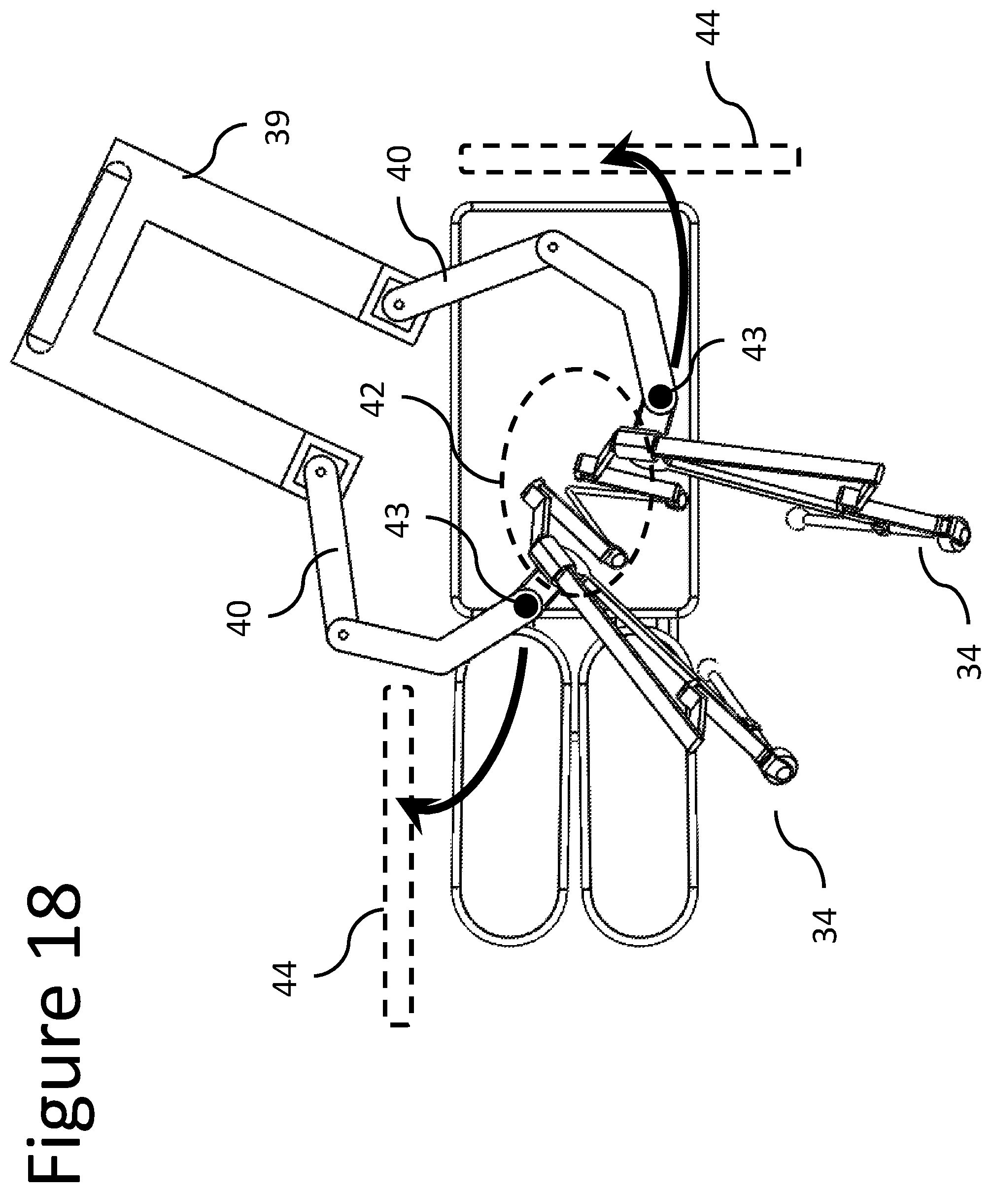
FIG. 18 illustrates a first solution of how the mechanical telemanipulators of the surgical platform of FIG. 16 can be removed from the surgical area during a surgical procedure;
FIG. 19 illustrates a second solution of how the mechanical telemanipulators of the surgical platform of FIG. 16 can be removed from the surgical area during a surgical procedure;
FIG. 20 shows a first perspective view of the surgical platform of FIG. 16 in a "compact storage" configuration;
FIG. 21 shows a second perspective view of the surgical platform of FIG. 16 in a "compact storage" configuration;
FIG. 22 shows the kinematics of a mechanical telemanipulator having a constraint on the slave manipulator and a RCM on the master manipulator according to an embodiment of the present invention;
FIG. 23 shows the kinematics of a mechanical telemanipulator with constraints on both the master and slave manipulator according to an embodiment of the present invention;
FIG. 24 shows the kinematic model of an embodiment of the current invention where an incision pointer is mounted on the mechanical telemanipulator so that the RCM can be localized and precisely with the body incision of the patient;
FIGS. 25 and 26 show two different views of the surgical platform, in a detailed stage of design, using two mechanical telemanipulators according to an embodiment of the current invention;
FIG. 27 shows a perspective view of a mechanical telemanipulator, in a detailed stage of design, according to an embodiment of the current invention.
DETAILED DESCRIPTION OF THE INVENTION
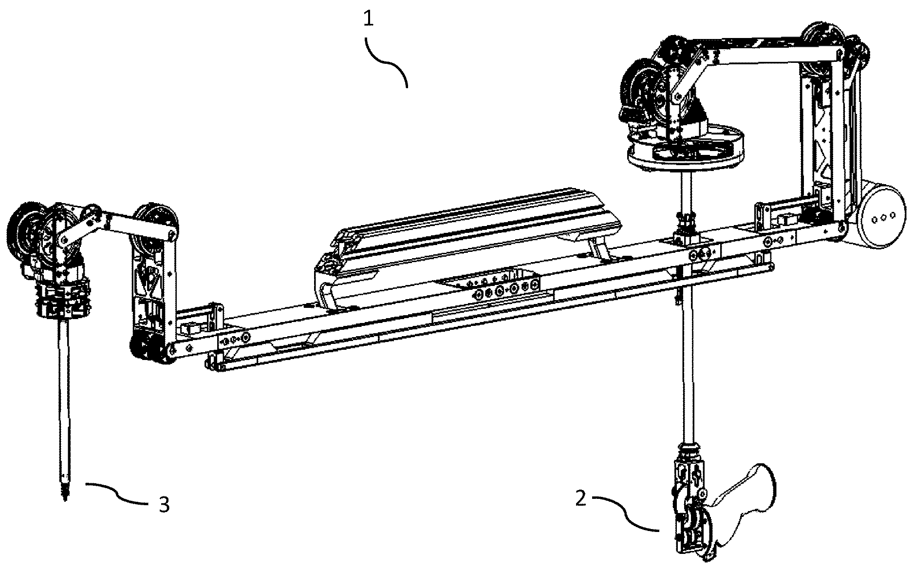
The mechanical telemanipulator 34, according to an embodiment of the present invention, is intended to be used in a surgical platform, like the mechanical telemanipulator 1 shown in FIG. 1, whose description is fully disclosed in WO2013014621 and which description is fully incorporated herein by reference as if presented herein in full.
One of the key features of this type of mechanical telemanipulators consists of its master-slave architecture, which enables a natural replication of the user hand movements, on a proximal handle 2, by a distal end-effector 3 on a remote location.
According to FIG. 2, the mechanical telemanipulator 1 may comprise: i) a master manipulator 4 having a number of master links 7, 8, 9, 10, 11, rotating over a plurality of master joints 12, 13, 14, 15, 16, a ii) a handle 2 for operating the mechanical telemanipulator 1, connected to the distal end of the master manipulator 4, iii) a slave manipulator 5 having a number of slave links 17, 18, 19, 20, 21 (generally corresponding to the master links 7, 8, 9, 10, 11), and rotating over a plurality of slave joints 22, 23, 24, 25, 26 (generally corresponding to the master joints 12, 13, 14, 15, 16); and iv) an end-effector 3 (instrument/tool or a gripper/holder) connected to the distal end of the slave manipulator 5. More particularly, the kinematic chain formed by the plurality of articulated slave links 17, 18, 19, 20, 21 and corresponding slave joints 22, 23, 24, 25, 26 of the slave manipulator 5, may be substantially identical to the kinematic chain formed by the plurality of articulated master links 7, 8, 9, 10, 11 and corresponding master joints 12, 13, 14, 15, 16 of the master manipulator 4.
Referring still to FIG. 2, the proximal master joint 12 and the proximal slave joint 22 can be considered to be merged in a single joint connecting the mechanical telemanipulator 1 to a ground 27. In the same way, the proximal master link 7 and the proximal slave link 17 can also be considered to be merged in a single connecting link.
The configuration of the mechanical telemanipulator 1 can also be described by considering the end-effector 3 to be part of the slave manipulator 5 and the handle 2 to be part of the master manipulator 4. In a broader sense, the links and joints composing the end-effector 3 can be considered distal slave links and joints, while the links and joints composing the handle 2 can be considered distal master links and joints.
The mechanical telemanipulator 1 further comprises mechanical transmission systems arranged to kinematically connect the slave manipulator 5 with the master manipulator 4 such that the movement (angle of joint) applied on each master joint of the master manipulator 4 is reproduced by the corresponding slave joint of the slave manipulator 5.
For each degree of freedom of the mechanical telemanipulator 1, different types of mechanical transmissions can be used. In order to minimize the system's overall friction, the mechanical transmission between the majority of the master and slave joints is essentially in the form of pulley-routed flexible elements, where each driven pulley of the slave joint is connected to the respective driving pulley of the master joint, by a multi-stage closed cable loop transmission. However, other types of mechanical transmission can be used, comprising rigid and/or geared elements.
Another key feature of the mechanical telemanipulator 1 disclosed in WO2013014621 lies in the mechanical constraint 28 of the mechanical telemanipulator which is configured to constraint movements of the slave manipulator 5 in correspondence with the constraints imposed by an incision realized on a patient. Referring to FIG. 2, in an embodiment of the invention, the mechanical constraint 28 is configured to ensure that, when the mechanical telemanipulator 1 is in operation, the master link 11 of the master manipulator 4 always translates along and rotates about a single point so that the corresponding slave link 21 always translates along and rotates about a fixed point in the space 29, also known as the Remote-Center-of-Motion, RCM.
Therefore, the movement applied on the handle 2, forces the movement of the master joints 12, 13, 14, 15, 16 of the master manipulator 4, by the direct mechanical transmission system and the mechanical constraint 28, to drive the respective movement of the slave joints 22, 23, 24, 25, 26 of the slave manipulator 5. As a result, the multi-articulated end-effector 3 connected to the distal end of the slave manipulator 5 is moved in an equivalent movement of the handle 2, while the slave link 21 always translates along and rotates about the RCM 29.
During a minimally invasive surgical procedure, the RCM 29 is brought in coincidence with the surgical incision point, reducing trauma to the patient and improving cosmetic outcomes of the surgery.
Some embodiments of the invention disclosed in WO2013014621 may have a few limitations in terms of its positioning over the patient. As can be seen in FIG. 3, with this specific kinematic model, an alignment 33 between the 1.sup.st degree-of-freedom, DOF, of the mechanical telemanipulator 1 and the incision 29 on the patient 30 is required. This prerequisite, together with the fact that the neutral position of instrument shaft 21 is perpendicular with the alignment line 33, limits the forward angulation that can be reached inside the patient and forces the distance between the master manipulator 4 and the slave manipulator 5 to be large in order to avoid collisions of the handle 2 with the patient 30 and surgical table 31. In addition, the fact that the handle 2 cannot be positioned over the patient 30, limits the ranges of procedures that can be done.
To overcome the above mentioned set of limitations, another embodiment of WO2013014621 can be formulated, as can be seen in FIG. 4. Due to its new kinematics and constraint setup (shown in FIG. 5), with this mechanical telemanipulator 34 the RCM 29 (and therefore the incision point on the patient) doesn't have to be aligned with the first DOF of the mechanical telemanipulator 34 and the neutral position of the instrument shaft 21 doesn't have to be perpendicular with any alignment line. As can be seen in FIG. 4, these features allow for much more flexibility in positioning the mechanical telemanipulator 34 over the patient 30, while allowing shorter distances between the master manipulator 4 and the slave manipulator 5, which results in a lighter and more compact system 1 that can be more easily integrated in the operating room workflow.
FIG. 5 shows the new kinematic model of the system, with a total of 6 degrees-of-freedom (excluding the three degrees-of-freedom of the handle 2 and end-effector 3) and the constraint 28, which is now fixed to a second ground 37 and not to the proximal master link 7, as in the embodiment 1. As can be seen in FIG. 6, this kinematics of the embodiment 34 has one more DOF that the kinematics of the embodiment 1, which consist in the master joint 35 and the correspondent slave joint 36.
FIGS. 7 to 12 show the mechanical telemanipulator 34 in different working configurations.
A key feature of this invention consist in the possibility to move the constraint 28 (and therefore the RCM 29) in the 3D space in relation to the ground 27, to which the mechanical telemanipulator 34 is fixed by the first joint 12 (FIGS. 13 and 14). This can be achieved by and articulated system 38 that can be fixed to a second ground 37 (FIG. 13) or directly to the ground 27 (FIG. 14). This feature allows for an increased flexibility in reaching an optimal position of the telemanipulator 34 over the patient, while allowing for a desired workspace inside the patient with an ideal ergonomy for the surgeon.
A surgical platform 45, which comprises at least one mechanical telemanipulator 34, can be seen in FIG. 15. It is arranged in a way that the mechanical telemanipulators 34 can be placed over the surgical table 31, while having their RCM 39 merged with the incision points in the patient.
According to FIGS. 16 and 17, the surgical platform 45, may further comprise a movable base 39, and at least one articulated positioning manipulator 40, whose distal extremity 41 is fixed to the mechanical telemanipulator 34 so that it can be moved over the surgical table 31 and stably fixed in specific positions of the 3D space. In other embodiments of the current invention, instead of a single movable base 39, each one of the two articulated positioning manipulators 40 may be mounted on a separate movable base, independent from the movable base of the other articulated positioning manipulator 40.
Each articulated positioning manipulator 40 should be gravity-compensated (together with the mechanical telemanipulator 34 that is being carried) by means of systems of counterweights and/or springs. In addition, each articulated positioning manipulator 40 should be provided with a system of clutches/brakes on each one of the joints so that they are blocked by default and can be released and moved when a switch 43 is pressed. By pressing the switch 43, the mechanical telemanipulator 34 can be moved in the 3D space to be positioned over the patient or to be removed from the surgical area 42 to a remote location 44, in particular during a surgical procedure (FIGS. 18 and 19) but also before or after. This feature is critical for an easy integration of the surgical platform with the operating room workflow, were the mechanical telemanipulators can be used interactively with other types of surgical instrumentation (for instance, standard laparoscopic instruments) during the same surgical procedure.
In order to be precisely positioned over the patient and aligned with the body incision of the patient, an incision pointer 47 (FIG. 24) can be mounted on each mechanical telemanipulator 34 during their positioning over the patient, when the detachable instrument containing the end-effector 3 is still not mounted on the mechanical telemanipulator 34. As can be seen in FIG. 24, the incision pointer 47 can be rigidly attached to the distal moving link 49 of the articulated system 38 so that its distal extremity is pointing to the RCM 29 of the mechanical telemanipulator 34 (whose 3D position with respect to the ground 27 is changing according to the positional configuration of the articulated system 38). Then, as soon as the distal extremity of the incision pointer 47 is brought to be substantially coincident to the incision of the patient body (where a surgical trocar may be in place) the 3D position of the mechanical telemanipulator 34 is blocked in the 3D space but releasing the switch 43 of the articulated positioning manipulator 40.
As shown in FIGS. 20 and 21, the surgical platform 45 allows for a compact storing position, where the mechanical telemanipulators 34 are brought by the articulated positioning manipulators 40 to a protected location over the platform's movable base 39. In the shown embodiment, the position of both telemanipulators is substantially vertical but in other embodiments of the current invention they may be in other special configurations (for instance, substantially horizontal).
FIGS. 25 and 26 show two different views of the surgical platform 45 in a more detailed stage of design, while FIG. 27 shows an embodiment of the current invention, used on the mechanical telemanipulator 34, where the articulated system 38 provides 2 degrees-of-freedom L1, L2 (corresponding to the linear displacement between the link 48 and the ground 27 and the linear displacement between the distal link 49 and the link 48) to the constraint 28.
While this invention has been shown and described with reference to particular embodiments thereof, it will be understood by those skilled in the art that various changes in form and details may be made therein without departing from the spirit and scope of the invention as defined by the appended claims. For instance, knowing that each master joint 12, 13, 14, 35, 15, 16 is kinematically connected with the corresponding slave joint 22, 23, 24, 36, 25, 26 another embodiment of the current invention can be achieved by placing the constraint 28 on a slave link 21 to have the RCM 29 on the master manipulator 4, around which the master link 11 would always rotate about and translate along (FIG. 22). Similarly, a different embodiment of the present invention could be reached by having the constraint 28m in the master link 11 and placing a second constraint 28s on the slave manipulator 5 (FIG. 23), so that the slave link 21 would always rotate about and translate along a point that is coincident with the incision.
* * * * *
References
D00000
D00001
D00002
D00003
D00004
D00005
D00006
D00007
D00008
D00009
D00010
D00011
D00012

D00013
D00014

D00015

D00016

D00017

D00018

D00019

D00020

D00021

XML
uspto.report is an independent third-party trademark research tool that is not affiliated, endorsed, or sponsored by the United States Patent and Trademark Office (USPTO) or any other governmental organization. The information provided by uspto.report is based on publicly available data at the time of writing and is intended for informational purposes only.
While we strive to provide accurate and up-to-date information, we do not guarantee the accuracy, completeness, reliability, or suitability of the information displayed on this site. The use of this site is at your own risk. Any reliance you place on such information is therefore strictly at your own risk.
All official trademark data, including owner information, should be verified by visiting the official USPTO website at www.uspto.gov. This site is not intended to replace professional legal advice and should not be used as a substitute for consulting with a legal professional who is knowledgeable about trademark law.