Multi-wavelength pulse oximetry
Wu , et al. Feb
U.S. patent number 10,568,525 [Application Number 15/376,542] was granted by the patent office on 2020-02-25 for multi-wavelength pulse oximetry. This patent grant is currently assigned to Fitbit, Inc.. The grantee listed for this patent is Fitbit, Inc.. Invention is credited to Peter W. Richards, Chris H. Sarantos, Anjian Wu, Shelten Gee Jao Yuen.


| United States Patent | 10,568,525 |
| Wu , et al. | February 25, 2020 |
Multi-wavelength pulse oximetry
Abstract
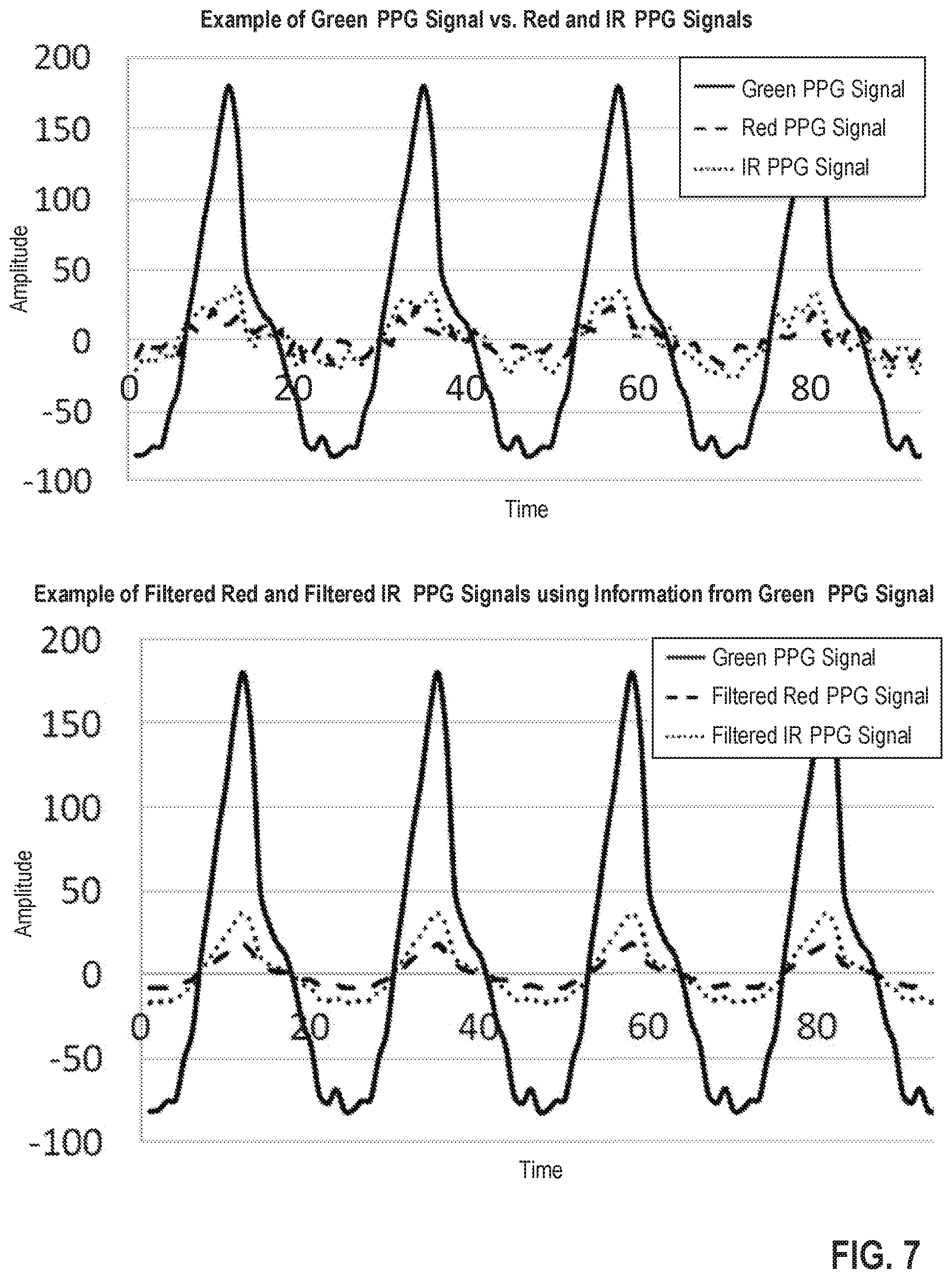
In one embodiment, a method for creating a blood oxygen saturation (SpO.sub.2) value, the method comprises receiving one or more photoplethysmography (PPG) signals for SpO.sub.2 detection from one or more PPG sensors; receiving one or more PPG signals for characterizing a heart rate from the one or more PPG sensors; using the one or more PPG signals for SpO.sub.2 detection, forming one or more SpO.sub.2 datasets wherein the SpO.sub.2 datasets respectively comprise one or more noise components; removing the one or more noise components from the one or more SpO.sub.2 datasets that are inconsistent with a feature of the one or more PPG signals characterizing the heart rate to produce one or more filtered SpO.sub.2 datasets; and using the one or more filtered SpO.sub.2 datasets, creating and storing the SpO.sub.2.
| Inventors: | Wu; Anjian (San Francisco, CA), Sarantos; Chris H. (San Francisco, CA), Richards; Peter W. (San Francisco, CA), Yuen; Shelten Gee Jao (San Francisco, CA) | ||||||||||
|---|---|---|---|---|---|---|---|---|---|---|---|
| Applicant: |
|
||||||||||
| Assignee: | Fitbit, Inc. (San Francisco,
CA) |
||||||||||
| Family ID: | 69590618 | ||||||||||
| Appl. No.: | 15/376,542 | ||||||||||
| Filed: | December 12, 2016 |
Related U.S. Patent Documents
| Application Number | Filing Date | Patent Number | Issue Date | ||
|---|---|---|---|---|---|
| 62266793 | Dec 14, 2015 | ||||
| Current U.S. Class: | 1/1 |
| Current CPC Class: | A61B 5/0205 (20130101); A61B 5/6824 (20130101); A61B 5/14552 (20130101); A61B 5/0004 (20130101); A61B 5/0022 (20130101); A61B 5/742 (20130101); A61B 5/7278 (20130101); A61B 5/7203 (20130101); A61B 5/14551 (20130101); A61B 5/02416 (20130101) |
| Current International Class: | A61B 5/0205 (20060101); A61B 5/00 (20060101); A61B 5/1455 (20060101); A61B 5/024 (20060101) |
References Cited [Referenced By]
U.S. Patent Documents
| 3608545 | September 1971 | Novack et al. |
| 4258719 | March 1981 | Lewyn |
| 4367752 | January 1983 | Jimenez et al. |
| 4771792 | September 1988 | Seale |
| 4781195 | November 1988 | Martin |
| 4846183 | July 1989 | Martin |
| 4960126 | October 1990 | Conlon |
| 5036856 | August 1991 | Thornton |
| 5101831 | April 1992 | Koyama et al. |
| 5301154 | April 1994 | Suga |
| 5318597 | June 1994 | Hauck et al. |
| 5490523 | February 1996 | Isaacson et al. |
| 5513649 | May 1996 | Gevins et al. |
| 5734625 | March 1998 | Kondo |
| 5738104 | April 1998 | Lo et al. |
| 5830137 | November 1998 | Scharf |
| 5954644 | September 1999 | Dettling et al. |
| 6076015 | June 2000 | Hartley et al. |
| 6099478 | August 2000 | Aoshima et al. |
| 6131076 | October 2000 | Stephan et al. |
| 6241684 | June 2001 | Amano et al. |
| 6289230 | September 2001 | Chaiken et al. |
| 6307576 | October 2001 | Rosenfeld |
| 6360113 | March 2002 | Dettling |
| 6402690 | June 2002 | Rhee et al. |
| 6418394 | July 2002 | Puolakanaho et al. |
| 6583369 | June 2003 | Montagnino et al. |
| 6585622 | July 2003 | Shum et al. |
| 6731967 | May 2004 | Turcott |
| 6882955 | April 2005 | Ohlenbusch et al. |
| 6959259 | October 2005 | Vock et al. |
| 6997882 | February 2006 | Parker et al. |
| 7020508 | March 2006 | Stivoric et al. |
| 7153262 | December 2006 | Stivoric et al. |
| 7171331 | January 2007 | Vock et al. |
| 7252639 | August 2007 | Kimura et al. |
| 7285090 | October 2007 | Stivoric et al. |
| 7334472 | February 2008 | Seo et al. |
| 7539532 | May 2009 | Tran |
| 7579946 | August 2009 | Case, Jr. |
| 7720306 | May 2010 | Gardiner et al. |
| 7909768 | March 2011 | Turcott |
| 7993276 | August 2011 | Nazarian et al. |
| 8040758 | October 2011 | Dickinson |
| 8073707 | December 2011 | Teller et al. |
| 8109858 | February 2012 | Redmann |
| 8140143 | March 2012 | Picard et al. |
| 8152745 | April 2012 | Smith et al. |
| 8157731 | April 2012 | Teller et al. |
| 8172761 | May 2012 | Rulkov et al. |
| 8199126 | June 2012 | Taubman |
| 8211503 | July 2012 | Tsao et al. |
| 8346328 | January 2013 | Mannheimer et al. |
| 8386042 | February 2013 | Yudovsky et al. |
| 8398546 | March 2013 | Pacione et al. |
| 8444578 | May 2013 | Bourget et al. |
| 8446275 | May 2013 | Utter, II |
| 8475367 | July 2013 | Yuen et al. |
| 8579827 | November 2013 | Rulkov et al. |
| 8641612 | February 2014 | Teller et al. |
| 8742325 | June 2014 | Droz et al. |
| 8792981 | July 2014 | Yudovsky et al. |
| 8868377 | October 2014 | Yuen et al. |
| 8909543 | December 2014 | Tropper et al. |
| 8920332 | December 2014 | Hong et al. |
| 8936552 | January 2015 | Kateraas et al. |
| 8945017 | February 2015 | Venkatraman et al. |
| 8948832 | February 2015 | Hong et al. |
| 8954135 | February 2015 | Yuen et al. |
| 8956303 | February 2015 | Hong et al. |
| 8961413 | February 2015 | Teller et al. |
| 8998815 | April 2015 | Venkatraman et al. |
| 9005129 | April 2015 | Venkatraman et al. |
| 9014790 | April 2015 | Richards et al. |
| 9031812 | May 2015 | Roberts et al. |
| 9042971 | May 2015 | Brumback et al. |
| 9044149 | June 2015 | Richards et al. |
| 9044150 | June 2015 | Brumback et al. |
| 9049998 | June 2015 | Brumback et al. |
| 9089760 | July 2015 | Tropper et al. |
| 9113794 | August 2015 | Hong et al. |
| 9113795 | August 2015 | Hong et al. |
| 9226663 | January 2016 | Fei |
| 9237855 | January 2016 | Hong et al. |
| 9282902 | March 2016 | Richards et al. |
| 9307917 | April 2016 | Hong et al. |
| 9314166 | April 2016 | Brady et al. |
| 9314197 | April 2016 | Eisen et al. |
| 9392946 | July 2016 | Sarantos et al. |
| 9402552 | August 2016 | Richards et al. |
| 9456787 | October 2016 | Venkatraman et al. |
| 9662053 | May 2017 | Richards et al. |
| 9775548 | October 2017 | Sarantos et al. |
| 10178973 | January 2019 | Venkatraman et al. |
| 10216893 | February 2019 | Hong et al. |
| 10216894 | February 2019 | Hong et al. |
| 2001/0044588 | November 2001 | Mault |
| 2002/0077536 | June 2002 | Diab et al. |
| 2002/0091329 | July 2002 | Heikkila et al. |
| 2002/0139936 | October 2002 | Dumas |
| 2003/0107487 | June 2003 | Korman et al. |
| 2003/0163710 | August 2003 | Ortiz et al. |
| 2003/0229276 | December 2003 | Sarussi et al. |
| 2004/0171969 | September 2004 | Socci et al. |
| 2004/0190085 | September 2004 | Silverbrook et al. |
| 2004/0236227 | November 2004 | Gueissaz |
| 2005/0020927 | January 2005 | Blondeau et al. |
| 2005/0054940 | March 2005 | Almen |
| 2005/0245793 | November 2005 | Hilton et al. |
| 2005/0253047 | November 2005 | Maegawa et al. |
| 2006/0052727 | March 2006 | Palestrant |
| 2006/0195020 | August 2006 | Martin et al. |
| 2007/0213020 | September 2007 | Novac |
| 2007/0219059 | September 2007 | Schwartz et al. |
| 2007/0265533 | November 2007 | Tran |
| 2008/0039729 | February 2008 | Cho et al. |
| 2008/0097221 | April 2008 | Florian |
| 2008/0214360 | September 2008 | Stirling et al. |
| 2008/0214903 | September 2008 | Orbach |
| 2009/0012433 | January 2009 | Fernstrom et al. |
| 2009/0132197 | May 2009 | Rubin et al. |
| 2009/0143655 | June 2009 | Shani |
| 2009/0163783 | June 2009 | Mannheimer et al. |
| 2009/0216499 | August 2009 | Tobola |
| 2009/0292332 | November 2009 | Li et al. |
| 2009/0318779 | December 2009 | Tran |
| 2010/0026995 | February 2010 | Merritt et al. |
| 2010/0063365 | March 2010 | Pisani et al. |
| 2010/0079291 | April 2010 | Kroll et al. |
| 2010/0106044 | April 2010 | Linderman |
| 2010/0113948 | May 2010 | Yang et al. |
| 2010/0152600 | June 2010 | Droitcour et al. |
| 2010/0204550 | August 2010 | Heneghan et al. |
| 2010/0249633 | September 2010 | Droitcour et al. |
| 2010/0274100 | October 2010 | Behar et al. |
| 2010/0292568 | November 2010 | Droitcour et al. |
| 2010/0298650 | November 2010 | Moon et al. |
| 2010/0298651 | November 2010 | Moon et al. |
| 2010/0298653 | November 2010 | McCombie et al. |
| 2010/0298661 | November 2010 | McCombie et al. |
| 2010/0331145 | December 2010 | Lakovic et al. |
| 2010/0331657 | December 2010 | Mensinger et al. |
| 2011/0009727 | January 2011 | Mensinger et al. |
| 2011/0032105 | February 2011 | Hoffman et al. |
| 2011/0066010 | March 2011 | Moon et al. |
| 2011/0112442 | May 2011 | Meger et al. |
| 2011/0118621 | May 2011 | Chu |
| 2011/0237911 | September 2011 | Lamego et al. |
| 2011/0237912 | September 2011 | Couronne et al. |
| 2011/0263950 | October 2011 | Larson et al. |
| 2011/0276304 | November 2011 | Yin et al. |
| 2012/0083705 | April 2012 | Yuen et al. |
| 2012/0083714 | April 2012 | Yuen et al. |
| 2012/0083715 | April 2012 | Yuen et al. |
| 2012/0083716 | April 2012 | Yuen et al. |
| 2012/0084053 | April 2012 | Yuen et al. |
| 2012/0084054 | April 2012 | Yuen et al. |
| 2012/0123232 | May 2012 | Najarian et al. |
| 2012/0140233 | June 2012 | Rockwell et al. |
| 2012/0143067 | June 2012 | Watson et al. |
| 2012/0150074 | June 2012 | Yanev et al. |
| 2012/0172733 | July 2012 | Park |
| 2012/0226471 | September 2012 | Yuen et al. |
| 2012/0226472 | September 2012 | Yuen et al. |
| 2012/0232432 | September 2012 | Kahn et al. |
| 2012/0245439 | September 2012 | Andre et al. |
| 2012/0253486 | October 2012 | Niemimaki |
| 2012/0255875 | October 2012 | Vicente et al. |
| 2012/0271180 | October 2012 | Ren et al. |
| 2012/0274508 | November 2012 | Brown et al. |
| 2012/0316471 | December 2012 | Rahman et al. |
| 2013/0009779 | January 2013 | Wittling et al. |
| 2013/0053661 | February 2013 | Alberth et al. |
| 2013/0073254 | March 2013 | Yuen et al. |
| 2013/0073255 | March 2013 | Yuen et al. |
| 2013/0077823 | March 2013 | Mestha et al. |
| 2013/0077826 | March 2013 | Cowperthwaite et al. |
| 2013/0079607 | March 2013 | Gareau et al. |
| 2013/0080113 | March 2013 | Yuen et al. |
| 2013/0106684 | May 2013 | Weast et al. |
| 2013/0151196 | June 2013 | Yuen et al. |
| 2013/0158369 | June 2013 | Yuen et al. |
| 2013/0173171 | July 2013 | Drysdale et al. |
| 2013/0191034 | July 2013 | Weast et al. |
| 2013/0211265 | August 2013 | Bedingham et al. |
| 2013/0218053 | August 2013 | Kaiser et al. |
| 2013/0245436 | September 2013 | Tupin, Jr. et al. |
| 2013/0261415 | October 2013 | Ashe |
| 2014/0039284 | February 2014 | Niwayama et al. |
| 2014/0073486 | March 2014 | Ahmed et al. |
| 2014/0074431 | March 2014 | Modi |
| 2014/0099614 | April 2014 | Hu et al. |
| 2014/0107493 | April 2014 | Yuen et al. |
| 2014/0135612 | May 2014 | Yuen et al. |
| 2014/0135631 | May 2014 | Brumback et al. |
| 2014/0142403 | May 2014 | Brumback et al. |
| 2014/0228649 | August 2014 | Rayner |
| 2014/0241626 | August 2014 | Sull et al. |
| 2014/0275821 | September 2014 | Beckman |
| 2014/0275852 | September 2014 | Hong et al. |
| 2014/0275854 | September 2014 | Venkatraman et al. |
| 2014/0276119 | September 2014 | Venkatraman et al. |
| 2014/0278139 | September 2014 | Hong et al. |
| 2014/0288390 | September 2014 | Hong et al. |
| 2014/0288391 | September 2014 | Hong et al. |
| 2014/0288392 | September 2014 | Hong et al. |
| 2014/0288435 | September 2014 | Richards et al. |
| 2014/0288436 | September 2014 | Venkatraman et al. |
| 2014/0288438 | September 2014 | Venkatraman et al. |
| 2014/0303523 | October 2014 | Hong et al. |
| 2014/0378786 | December 2014 | Hong et al. |
| 2014/0378787 | December 2014 | Brumback et al. |
| 2014/0378844 | December 2014 | Fei |
| 2014/0378872 | December 2014 | Hong et al. |
| 2015/0025393 | January 2015 | Hong et al. |
| 2015/0025394 | January 2015 | Hong et al. |
| 2015/0173631 | June 2015 | Richards et al. |
| 2015/0196256 | July 2015 | Venkatraman et al. |
| 2015/0201853 | July 2015 | Hong et al. |
| 2015/0201854 | July 2015 | Hong et al. |
| 2015/0223708 | August 2015 | Richards et al. |
| 2015/0230743 | August 2015 | Silveira et al. |
| 2015/0230761 | August 2015 | Brumback et al. |
| 2015/0282713 | October 2015 | Fei |
| 2015/0351646 | December 2015 | Cervini |
| 2015/0366469 | December 2015 | Harris et al. |
| 2015/0366504 | December 2015 | Connor et al. |
| 2016/0034634 | February 2016 | Hong et al. |
| 2016/0058309 | March 2016 | Han |
| 2016/0058312 | March 2016 | Han et al. |
| 2016/0113585 | April 2016 | Uedaira et al. |
| 2016/0183818 | June 2016 | Richards et al. |
| 2016/0302706 | October 2016 | Richards et al. |
| 2016/0345881 | December 2016 | Sarantos et al. |
| 2017/0020659 | January 2017 | Hyde et al. |
| 2017/0027523 | February 2017 | Venkatraman et al. |
| 2017/0164848 | June 2017 | Nadeau et al. |
| 2017/0311825 | November 2017 | Weekly et al. |
| 2018/0108802 | April 2018 | Chen |
| 2019/0082985 | March 2019 | Hong et al. |
| 1623175 | Jun 2005 | CN | |||
| 1729933 | Aug 2006 | CN | |||
| 100362963 | Jan 2008 | CN | |||
| 101615098 | Dec 2009 | CN | |||
| 101730503 | Jun 2010 | CN | |||
| 101742981 | Jun 2010 | CN | |||
| 102008811 | Apr 2011 | CN | |||
| 202069586 | Dec 2011 | CN | |||
| 102389313 | Mar 2012 | CN | |||
| 102551686 | Jul 2012 | CN | |||
| 102750015 | Oct 2012 | CN | |||
| 102781310 | Nov 2012 | CN | |||
| 103093420 | May 2013 | CN | |||
| 1 297 784 | Apr 2003 | EP | |||
| 1 586 353 | Oct 2005 | EP | |||
| 1 721 237 | Aug 2012 | EP | |||
| WO 2014/091424 | Jun 2014 | WO | |||
| WO 2014/091424 | Jun 2014 | WO | |||
| WO 2017190051 | Nov 2017 | WO | |||
Other References
|
US. Office Action, dated Aug. 4, 2014, issued in U.S. Appl. No. 13/924,784. cited by applicant . U.S. Notice of Allowance, dated Nov. 19, 2014, issued in U.S. Appl. No. 13/924,784. cited by applicant . U.S. Office Action, dated Oct. 22, 2014, issued in U.S. Appl. No. 14/290,884. cited by applicant . U.S. Notice of Allowance, dated Feb. 6, 2015, issued in U.S. Appl. No. 14/290,884. cited by applicant . U.S. Office Action, dated Jun. 22, 2015, issued in U.S. Appl. No. 14/693,710. cited by applicant . U.S. Notice of Allowance, dated Jul. 27, 2015, issued in U.S. Appl. No. 14/693,710. cited by applicant . U.S. Notice of Allowance, dated Apr. 15, 2016, issued in U.S. Appl. No. 14/954,753. cited by applicant . U.S. Office Action, dated Oct. 26, 2016, issued in U.S. Appl. No. 15/195,911. cited by applicant . U.S. Notice of Allowance, dated Jan. 23, 2017, issued in U.S. Appl. No. 15/195,911. cited by applicant . U.S. Notice of Allowance, dated Sep. 23, 2014, issued in U.S. Appl. No. 14/292,669. cited by applicant . U.S. Notice of Allowance (Corrected Notice of Allowability), dated Oct. 14, 2014, issued in U.S. Appl. No. 14/292,669. cited by applicant . U.S. Notice of Allowance (Corrected Notice of Allowability), dated Dec. 31, 2014, issued in U.S. Appl. No. 14/292,669. cited by applicant . U.S. Notice of Allowance, dated Oct. 14, 2014, issued in U.S. Appl. No. 14/295,144. cited by applicant . U.S. Notice of Allowance, dated Dec. 3, 2014, issued in U.S. Appl. No. 14/295,144. cited by applicant . U.S. Notice of Allowance, dated Sep. 26, 2014, issued in U.S. Appl. No. 14/295,158. cited by applicant . U.S. Notice of Allowance (Corrected Notice of Allowability), dated Dec. 31, 2014, issued in U.S. Appl. No. 14/295,158. cited by applicant . U.S. Office Action, dated Jan. 23, 2015, issued in U.S. Appl. No. 14/507,184. cited by applicant . U.S. Final Office Action, dated May 11, 2015, issued in U.S. Appl. No. 14/507,184. cited by applicant . U.S. Notice of Allowance, dated Aug. 11, 2015, issued in U.S. Appl. No. 14/507,184. cited by applicant . U.S. Notice of Allowance (Corrected Notice of Allowability), dated Dec. 18, 2015, issued in U.S. Appl. No. 14/507,184. cited by applicant . U.S. Office Action, dated Jan. 26, 2015, issued in U.S. Appl. No. 14/295,161. cited by applicant . U.S. Notice of Allowance, dated Apr. 14, 2015, issued in U.S. Appl. No. 14/295,161. cited by applicant . U.S. Notice of Allowance, dated Jul. 28, 2015, issued in U.S. Appl. No. 14/295,161. cited by applicant . U.S. Office Action, dated May 11, 2015, issued in U.S. Appl. No. 14/673,630. cited by applicant . U.S. Notice of Allowance, dated Nov. 25, 2015, issued in U.S. Appl. No. 14/673,630. cited by applicant . U.S. Notice of Allowance (Corrected Notice of Allowability), dated Mar. 21, 2016, issued in U.S. Appl. No. 14/673,630. cited by applicant . U.S. Office Action, dated Jan. 27, 2015, issued in U.S. Appl. No. 14/507,173. cited by applicant . U.S. Notice of Allowance, dated Apr. 17, 2015, issued in U.S. Appl. No. 14/507,173. cited by applicant . U.S. Notice of Allowance (Corrected Notice of Allowability), dated Jul. 16, 2015, issued in U.S. Appl. No. 14/507,173. cited by applicant . U.S. Office Action, dated Jun. 8, 2015, issued in U.S. Appl. No. 14/673,634. cited by applicant . U.S. Final Office Action, dated Nov. 4, 2015, issued in U.S. Appl. No. 14/673,634. cited by applicant . U.S. Office Action, dated Jul. 13, 2016, issued in U.S. Appl. No. 14/673,634. cited by applicant . U.S. Office Action, dated Feb. 9, 2017, issued in U.S. Appl. No. 14/673,634. cited by applicant . U.S. Final Office Action, dated Aug. 9, 2017, issued in U.S. Appl. No. 14/673,634. cited by applicant . U.S. Office Action, dated Mar. 27, 2018, issued in U.S. Appl. No. 14/673,634. cited by applicant . U.S. Office Action, dated Aug. 5, 2014, issued in U.S. Appl. No. 14/292,673. cited by applicant . U.S. Notice of Allowance, dated Dec. 8, 2014, issued in U.S. Appl. No. 14/292,673. cited by applicant . U.S. Notice of Allowance (Corrected Notice of Allowability), dated Mar. 5, 2015, issued in U.S. Appl. No. 14/292,673. cited by applicant . U.S. Office Action, dated Sep. 18, 2014, issued in U.S. Appl. No. 14/295,059. cited by applicant . U.S. Notice of Allowance, dated Jan. 28, 2015, issued in U.S. Appl. No. 14/295,059. cited by applicant . U.S. Notice of Allowance (Corrected Notice of Allowability), dated Mar. 11, 2015, issued in U.S. Appl. No. 14/295,059. cited by applicant . U.S. Office Action, dated Dec. 24, 2014, issued in U.S. Appl. No. 14/295,076. cited by applicant . U.S. Final Office Action, dated Apr. 15, 2015, issued in U.S. Appl. No. 14/295,076. cited by applicant . U.S. Office Action, dated Oct. 22, 2015, issued in U.S. Appl. No. 14/295,076. cited by applicant . U.S. Notice of Allowance, dated May 24, 2016, issued in U.S. Appl. No. 14/295,076. cited by applicant . U.S. Office Action, dated Jan. 12, 2018, issued in U.S. Appl. No. 15/246,387. cited by applicant . U.S. Notice of Allowance, dated Aug. 29, 2018, issued in U.S. Appl. No. 15/246,387. cited by applicant . U.S. Office Action, dated Jul. 31, 2014, issued in U.S. Appl. No. 14/295,122. cited by applicant . U.S. Notice of Allowance, dated Nov. 24, 2014, issued in U.S. Appl. No. 14/295,122. cited by applicant . U.S. Notice of Allowance (Corrected Notice of Allowability), dated Jan. 5, 2015, issued in U.S. Appl. No. 14/295,122. cited by applicant . U.S. Office Action dated Dec. 22, 2016, issued in U.S. Appl. No. 14/599,039. cited by applicant . U.S. Final Office Action dated Aug. 3, 2017, issued in U.S. Appl. No. 14/599,039. cited by applicant . U.S. Office Action, dated Mar. 14, 2014, issued in U.S. Appl. No. 14/154,009. cited by applicant . U.S. Office Action, dated Sep. 29, 2014, issued in U.S. Appl. No. 14/154,009. cited by applicant . U.S. Notice of Allowance, dated Jan. 21, 2015, issued in U.S. Appl. No. 14/154,009. cited by applicant . U.S. Office Action, dated Nov. 25, 2014, issued in U.S. Appl. No. 14/154,019. cited by applicant . U.S. Notice of Allowance, dated Mar. 20, 2015, issued in U.S. Appl. No. 14/154,019. cited by applicant . U.S. Notice of Allowance (Corrected Notice of Allowability), dated May 14, 2015, issued in U.S. Appl. No. 14/154,019. cited by applicant . U.S. Office Action, dated Jul. 24, 2018, issued in U.S. Appl. No. 14/696,256. cited by applicant . U.S. Final Office Action, dated Feb. 26, 2019, issued in U.S. Appl. No. 14/696,256. cited by applicant . U.S. Office Action, dated Dec. 10, 2014, issued in U.S. Appl. No. 14/484,104. cited by applicant . U.S. Notice of Allowance, dated Mar. 19, 2015, issued in U.S. Appl. No. 14/484,104. cited by applicant . U.S. Notice of Allowance (Corrected Notice of Allowability), dated May 6, 2015, issued in U.S. Appl. No. 14/484,104. cited by applicant . U.S. Office Action, dated Dec. 4, 2014, issued in U.S. Appl. No. 14/216,743. cited by applicant . U.S. Final Office Action, dated Apr. 8, 2015, issued in U.S. Appl. No. 14/216,743. cited by applicant . U.S. Office Action, dated Oct. 2, 2015, issued in U.S. Appl. No. 14/216,743. cited by applicant . U.S. Final Office Action, dated Feb. 8, 2016, issued in U.S. Appl. No. 14/216,743. cited by applicant . U.S. Office Action, dated May 16, 2016, issued in U.S. Appl. No. 14/216,743. cited by applicant . U.S. Office Action, dated Jan. 13, 2017, issued in U.S. Appl. No. 14/216,743. cited by applicant . US Examiner's Answer to Appeal Brief before the Patent Trial and Appeal Board [in response to the appeal brief filed Sep. 12, 2017 appealing from the Office action dated Jan. 3, 2017], dated Nov. 30, 2017, issued in U.S. Appl. No. 14/216,743. cited by applicant . US Patent Trial and Appeal Board's Decision on Appeal, dated Oct. 9, 2018, issued in U.S. Appl. No. 14/216,743. cited by applicant . U.S. Notice of Allowance, dated Dec. 17, 2018, issued in U.S. Appl. No. 14/216,743. cited by applicant . U.S. Office Action, dated Mar. 12, 2015, issued in U.S. Appl. No. 14/481,020. cited by applicant . U.S. Final Office Action, dated Jul. 7, 2015, issued in U.S. Appl. No. 14/481,020. cited by applicant . U.S. Office Action, dated Oct. 27, 2015, issued in U.S. Appl. No. 14/481,020. cited by applicant . U.S. Final Office Action, dated May 13, 2016, issued in U.S. Appl. No. 14/481,020. cited by applicant . US Examiner's Answer to Appeal Brief before the Patent Trial and Appeal Board [in response to the appeal brief filed Dec. 9, 2016 appealing from the Office action dated May 13, 2016], dated Jan. 23, 2017, issued in U.S. Appl. No. 14/481,020. cited by applicant . US Patent Trial and Appeal Board's Decision on Appeal, dated Sep. 14, 2018, issued in U.S. Appl. No. 14/481,020. cited by applicant . U.S. Notice of Allowance, dated Nov. 29, 2018, issued in U.S. Appl. No. 14/481,020. cited by applicant . U.S. Office Action, dated Aug. 22, 2014, issued in U.S. Appl. No. 14/250,256. cited by applicant . U.S. Final Office Action, dated Nov. 21, 2014, issued in U.S. Appl. No. 14/250,256. cited by applicant . U.S. Office Action, dated Jul. 8, 2015, issued in U.S. Appl. No. 14/250,256. cited by applicant . U.S. Final Office Action, dated Oct. 23, 2015, issued in U.S. Appl. No. 14/250,256. cited by applicant . U.S. Office Action, dated Mar. 17, 2016, issued in U.S. Appl. No. 14/250,256. cited by applicant . U.S. Final Office Action, dated Jun. 29, 2016, issued in U.S. Appl. No. 14/250,256. cited by applicant . U.S. Office Action, dated Jan. 9, 2017, issued in U.S. Appl. No. 14/250,256. cited by applicant . US Examiner's Answer to the Appeal Brief before the Patent Trial and Appeal Board [in response to the appeal brief filed Jul. 11, 2017 appealing from the Office action dated Jan. 9, 2017], dated Aug. 24, 2017, issued in U.S. Appl. No. 14/250,256. cited by applicant . US Patent Trial and Appeal Board's Decision on Appeal, dated Oct. 9, 2018, issued in U.S. Appl. No. 14/250,256. cited by applicant . U.S. Notice of Allowance, dated Mar. 29, 2019, issued in U.S. Appl. No. 14/250,256. cited by applicant . U.S. Office Action, dated Oct. 7, 2014, issued in U.S. Appl. No. 14/481,762. cited by applicant . U.S. Final Office Action, dated Dec. 19, 2014, issued in U.S. Appl. No. 14/481,762. cited by applicant . U.S. Office Action, dated Jul. 7, 2015, issued in U.S. Appl. No. 14/481,762. cited by applicant . U.S. Final Office Action, dated Nov. 5, 2015, issued in U.S. Appl. No. 14/481,762. cited by applicant . U.S. Office Action, dated May 11, 2016, issued in U.S. Appl. No. 14/481,762. cited by applicant . U.S. Final Office Action, dated Oct. 19, 2016, issued in U.S. Appl. No. 14/481,762. cited by applicant . U.S. Office Action, dated Apr. 12, 2017, issued in U.S. Appl. No. 14/481,762. cited by applicant . U.S. Office Action, dated Nov. 19, 2015, issued in U.S. Appl. No. 14/724,750. cited by applicant . U.S. Notice of Allowance, dated Mar. 8, 2016, issued in U.S. Appl. No. 14/724,750. cited by applicant . U.S. Office Action dated Sep. 8, 2016, issued in U.S. Appl. No. 15/192,447. cited by applicant . U.S. Final Office Action dated Feb. 7, 2017, issued in U.S. Appl. No. 15/192,447. cited by applicant . U.S. Notice of Allowance dated May 24, 2017, issued in U.S. Appl. No. 15/192,447. cited by applicant . U.S. Office Action dated Mar. 15, 2017, issued in U.S. Appl. No. 15/370,303. cited by applicant . U.S. Final Office Action dated Aug. 1, 2017, issued in U.S. Appl. No. 15/370,303. cited by applicant . U.S. Office Action dated Jan. 11, 2018, issued in U.S. Appl. No. 15/370,303. cited by applicant . U.S. Final Office Action dated Jul. 25, 2018, issued in U.S. Appl. No. 15/370,303. cited by applicant . U.S. Office Action dated May 24, 2019, issued in U.S. Appl. No. 15/370,303. cited by applicant . U.S. Office Action, dated Oct. 7, 2014, issued in U.S. Appl. No. 14/292,844. cited by applicant . U.S. Notice of Allowance, dated Feb. 9, 2015, issued in U.S. Appl. No. 14/292,844. cited by applicant . U.S. Office Action, dated Jul. 6, 2015, issued in U.S. Appl. No. 14/640,281. cited by applicant . U.S. Final Office Action, dated Nov. 12, 2015, issued in U.S. Appl. No. 14/640,281. cited by applicant . U.S. Office Action, dated Oct. 6, 2016, issued in U.S. Appl. No. 14/640,281. cited by applicant . U.S. Final Office Action, dated May 4, 2017, issued in U.S. Appl. No. 14/640,281. cited by applicant . U.S. Office Action, dated Jun. 29, 2018, issued in U.S. Appl. No. 14/640,281. cited by applicant . U.S. Final Office Action, dated Feb. 21, 2019, issued in U.S. Appl. No. 14/640,281. cited by applicant . U.S. Notice of Allowance, dated Aug. 2, 2019, issued in U.S. Appl. No. 14/640,281. cited by applicant . U.S. Office Action, dated Mar. 11, 2019, issued in U.S. Appl. No. 15/582,240. cited by applicant . U.S. Notice of Allowance, dated Jun. 14, 2019, issued in U.S. Appl. No. 15/582,240. cited by applicant . U.S. Office Action, dated Mar. 13, 2014, issued in U.S. Appl. No. 14/073,657. cited by applicant . Chinese First Office Action dated Sep. 27, 2016 issued in Application No. CN 201410018701.8. cited by applicant . Chinese Second Office Action dated Jun. 13, 2017 issued in Application No. CN 201410018701.8. cited by applicant . Chinese First Office Action dated Aug. 7, 2015 issued in Application No. CN 201410243180.6. cited by applicant . Chinese First Office Action dated Sep. 2, 2016 issued in Application No. CN 201510745382.5. cited by applicant . Chinese Second Office Action dated Mar. 22, 2017 issued in Application No. CN 201510745382.5. cited by applicant . Chinese First Office Action dated Mar. 22, 2018 issued in Application No. CN 201610284612.7. cited by applicant . Chinese Second Office Action dated Nov. 6, 2018 issued in Application No. CN 201610284612.7. cited by applicant . Chinese First Office Action dated Aug. 3, 2016 issued in Application No. CN 201410243169.X. cited by applicant . Chinese Second Office Action dated Mar. 27, 2017 issued in Application No. CN 201410243169.X. cited by applicant . Chinese Third Office Action dated Sep. 28, 2017 issued in Application No. CN 201410243169.X. cited by applicant . Chinese First Office Action dated Sep. 26, 2016 issued in Application No. CN 201410243178.9. cited by applicant . Chinese Second Office Action dated Jun. 15, 2017 issued in Application No. CN 201410243178.9. cited by applicant . Chinese First Office Action dated Mar. 3, 2017 issued in Application No. CN 201610622453.7. cited by applicant . Chinese Second Office Action dated Sep. 19, 2017 issued in Application No. CN 201610622453.7. cited by applicant . Chinese Third Office Action dated Jan. 24, 2018 issued in Application No. CN 201610622453.7. cited by applicant . Chinese Fourth Office Action dated Jun. 1, 2018 issued in Application No. CN 201610622453.7. cited by applicant . Chinese First Office Action dated Jul. 13, 2017 issued in Application No. CN 201610621114.7. cited by applicant . Chinese Second Office Action dated Apr. 9, 2018 issued in Application No. CN 201610621114.7. cited by applicant . Chinese Third Office Action dated Sep. 14, 2018 issued in Application No. CN 201610621114.7. cited by applicant . Chinese First Office Action dated Jan. 14, 2019 issued in Application No. CN 201510117698.X. cited by applicant . Chinese Second Office Action dated Jun. 21, 2019 issued in Application No. CN 201510117698.X. cited by applicant . European Extended Search Report dated Oct. 25, 2016 issued in Application No. EP 16 16 8661.3. cited by applicant . European Office Action dated Mar. 19, 2019 issued in Application No. EP 16 16 8661.3. cited by applicant . International Search Report and Written Opinion--PCT/US2017/030190--ISA/US--dated Jul. 7, 2017 (dated Jul. 7, 2017). cited by applicant . Litigation Document--"Complaint for Patent Infringement," filed Sep. 3, 2015, in U.S. District Court of Delaware (Court Docket No. 1: 15-cv-00775-RGA). cited by applicant . Litigation Document--"Report on the Filing or Determination of an Action Regarding a Patent or Trademark," filed Sep. 3, 2015, in U.S. District Court of Delaware (Court Docket No. 1: 15-cv-00775-RGA). cited by applicant . Litigation Document--"Complaint for Patent Infringement," filed Oct. 29, 2015, in U.S. District Court of Delaware (Court Docket No. 1:15-cv-00990-RGA) [Re: U.S. Pat. No. 8,868,377, U.S. Pat. No. 8,920,332, and U.S. Pat. No. 9,089,760]. cited by applicant . Litigation Document--"Report on the Filing or Determination of an Action Regarding a Patent or Trademark," filed Oct. 29, 2015, in U.S. District Court of Delaware (Court Docket No. 1:15-cv-00990-RGA) [Re: U.S. Pat. No. 8,868,377, U.S. Pat. No. 8,920,332, and U.S. Pat. No. 9,089,760]. cited by applicant . Litigation Document--"Order No. 24: Initial Determination Granting Respondents' Motion for Summary Determination of Invalidity under 35 U.S.C. .sctn. 101 with respect to all Three Asserted Patents and Terminating the Investigation in its Entirety," filed Jul. 19, 2016, in United States International Trade Commission, Washington, D.C. (Investigation No. 337-TA-973) [In the Matter of Certain Wearable Activity Tracking Devices, Systems, and Components Thereof]. cited by applicant . Litigation Document--"Respondents' Opposition to Complainant's Petition for Review of the Initial Determination Granting Summary Determination that the Asserted Patents are Directed to Ineligible Subject Matter under 35 U.S.C. .sctn. 101," filed Aug. 8, 2016, in United States International Trade Commission, Washington, D.C. (Investigation No. 337-TA-973) (4446833v1/014972) [In the Matter of Certain Wearable Activity Tracking Devices, Systems, and Components Thereof]. cited by applicant . Litigation Document--"Declaration of Majid Sarrafzadeh in Support of Complainant's Brief in Opposition to Respondents' Motion for Summary Determination that the Asserted Patents are Directed to Ineligible Subject Matter under 35 U.S.C. .sctn. 101," filed Jun. 2, 2016, in United States International Trade Commission, Washington, D.C. (Investigation No. 37-TA-973) [In the Matter of Certain Wearable Activity Tracking Devices, Systems, and Components Thereof] [Exhibit 7]. cited by applicant . Litigation Document--"Kiaei Declaration in Support of Complainant's Supplemental Brief Regarding Construction of "Operating the Heart Rate Monitor in a Worn Detection Mode" under 35 U.S.C. .sctn. 112(f)," filed Apr. 29, 2016, in United States International Trade Commission, Washington, D.C. (Investigation No. 37-TA-973) [in the Matter of Certain Wearable Activity Tracking Devices, Systems, and Components Thereof] [Exhibit 8]. cited by applicant . Litigation Document--"Memorandum in Support of Respondents' Motion for Summary Determination that the Asserted Patents are Directed to Ineligible Subject Matter under 35 U.S.C. .sctn. 101," filed May 23, 2016, in United States International Trade Commission, Washington, D.C. (Investigation No. 337-TA-973) (44325007v1/014972) [In the Matter of Certain Wearable Activity Tracking Devices, Systems, and Components Thereof]. cited by applicant . Litigation Document--"Grimes Declaration in Support of Complainant's Brief in Opposition to Respondents' Motion for Summary Determination that the Asserted Patents are Directed to Ineligible Subject Matter under 35 U.S.C. .sctn. 101," filed Jun. 2, 2016, in United States International Trade Commission, Washington, D.C. (Investigation No. 37-TA-973) [In the Matter of Certain Wearable Activity Tracking Devices, Systems, and Components Thereof] [Exhibit 28]. cited by applicant . Litigation Document--"Complainant's Brief in Opposition to Respondents' Motion for Summary Determination that the Asserted Patents are Directed to Ineligible Subject Matter under 35 U.S.C. .sctn. 101," filed Jun. 2, 2016, in United States International Trade Commission, Washington, D.C. (Investigation No. 337-TA-973) [In the Matter of Certain Wearable Activity Tracking Devices, Systems, and Components Thereof]. cited by applicant . Litigation Document--"Complainant's Petition for Review of the Initial Determination Granting Summary Determination that the Asserted Patents are Directed to Ineligible Subject Matter under 35 U.S.C. .sctn. 101," filed Aug. 1, 2016, in United States International Trade Commission, Washington, D.C. (Investigation No. 337-TA-973) [In the Matter of Certain Wearable Activity Tracking Devices, Systems, and Components Thereof]. cited by applicant . Litigation Document--"Summary Pursuant to 19 C.F.R. .sctn. 210.43(b)(2) of Complainant's Petition for Review of the Initial Determination Granting Summary Determination that the Asserted Patents are Directed to Ineligible Subject Matter under 35 U.S.C. .sctn. 101," filed Aug. 1, 2016, in United States International Trade Commission, Washington, D.C. (Investigation No. 337-TA-973) [In the Matter of Certain Wearable Activity Tracking Devices, Systems, and Components Thereof]. cited by applicant . Litigation Document--"Notice of Commission Determination to Review an Initial Determination Granting Respondents' Motion for Summary Determination that Certain Asserted Claims are Directed to Ineligible Subject Matter under 35 U.S.C. .sctn. 101; and on Review to Remand the Investigation to the Presiding Administrative Law Judge," issued Sep. 7, 2016, in United States International Trade Commission, Washington, D.C. (Investigation No. 337-TA-973) [In the Matter of Certain Wearable Activity Tracking Devices, Systems, and Components Thereof]. cited by applicant . U.S. Appl. No. 61/736,310, filed Dec. 12, 2012, William Ahmed et al., entitled "Fitness Monitoring Systems and Methods Based on Continuous Collection of Physiological Data," 61pp [Exhibit 4]. cited by applicant . U.S. Appl. No. 61/696,525, filed Sep. 4, 2012, William Ahmed et al., entitled "Fitness Monitoring Systems and Methods Based on Continuous Collection of Physiological Data," 47pp [Exhibit 5]. cited by applicant . Gasparrini et al. (2013) "Evaluation and Possible Improvements of the ANT Protocol for Home Heart Monitoring Applications," IEEE, 978-1-4673-2874-6/13, 7pp [Exhibit 6]. cited by applicant . "UP3.TM., The world's most advanced tracker," (Oct. 14, 2015) Jawbone, 10pp [Exhibit 12]. cited by applicant . "UP4.TM., A fitness tracker so advanced it pays," (Oct. 14, 2015) Jawbone, 12pp [Exhibit 13]. cited by applicant . "User's Guide, MIO Drive+ Petite," User's guide and how-to videos available at www.mioglobal.com, 3pp [Exhibit 16]. cited by applicant . "SOLO 915, Heart Rate + Calorie Monitor," (2009) SPORTLINE.RTM., [retrieved on Oct. 15, 2010 at www.sportline.com] 25pp [Exhibit 17]. cited by applicant . U.S. Notice of Allowance dated Oct. 14, 2014 issued in U.S. Appl. No. 14/295,144, 5pp [Exhibit 18]. cited by applicant . "Health Touch.TM. Plus User Guide," (2011) Timex Group USA, Inc., 12pp [Exhibit 18]. cited by applicant . Czarnul, Pawel (Jun. 6-8, 2013) "Design of a Distributed System using Mobile Devices and Workflow Management for Measurement and Control of a Smart Home and Health," Sopot, Poland, IEEE, pp. 184-192, 10pp [Exhibit 19]. cited by applicant . Rabinovich, Roberto A., and Louvaris, Zafeiris et al. (Feb. 8, 2013) "Validity of Physical Activity Monitors During Daily Life in Patients With COPD," ERJ Express, European Respiratory Society, 28pp [Exhibit 24]. cited by applicant . Horvath et al. (2007) "The effect of pedometer position and normal gait asymmetry on step count accuracy," Appl. Physiol. Nutr. Metab., 32:409-415, 8pp [Exhibit 32]. cited by applicant . Graser et al. (2007) "Effects of Placement, Attachment, and Weight Classification on Pedometer Accuracy," Journal of Physical Activity and Health, 4(4):359-369, 13pp [Exhibit 33]. cited by applicant . Vyas et al. (2012) "Machine Learning and Sensor Fusion for Estimating Continuous Energy Expenditure," AI Magazine, pp. 55-61, 13pp [Exhibit 42]. cited by applicant . "New Lifestyles, NL-800 Activity Monitor, User's guide & record book," (2005), New Lifestyles, Inc., 37pp. cited by applicant . "StepWatch Step Activity Monitor, U.S. Pat. No. 5,485,402," (2001) StepWatch.TM., Prosthetics Research Study,7pp. cited by applicant . Litigation Document--"Plaintiff's Original Complaint for Patent Infringement," filed Jan. 4, 2016, in U.S. District Court for the Eastern District of North Carolina (Court Docket No. 5:16-cv-00002-FL) [Re: U.S. Pat. No. 8,923,941, U.S. Pat. No. 8,886,269, U.S. Pat. No. 8,929,965 and U.S. Pat. No. 8,989,830], 11 pages. cited by applicant . U.S. Appl. No. 14/214,655, filed Mar. 14, 2014, Hong et al. cited by applicant . U.S. Appl. No. 15/494,257, filed Apr. 21, 2017, Richards et al. cited by applicant. |
Primary Examiner: Winakur; Eric F
Assistant Examiner: Mustansir; Abid A
Attorney, Agent or Firm: Weaver Austin Villeneuve & Sampson LLP
Parent Case Text
CROSS-REFERENCE TO RELATED APPLICATIONS; BENEFIT CLAIM
This application claims the benefit under 35 U.S.C. .sctn. 119(e) of provisional application 62/266,793, filed Dec. 14, 2015, the entire contents of which is hereby incorporated by reference as if fully set forth herein.
Claims
What is claimed is:
1. A method for determining a blood oxygen saturation (SpO.sub.2) value, the method comprising: receiving one or more photoplethysmography (PPG) signals for SpO.sub.2 detection from one or more PPG sensors; receiving one or more PPG signals for characterizing a heart rate from the one or more PPG sensors; forming one or more SpO.sub.2 datasets using the one or more PPG signals for SpO.sub.2 detection, wherein the one or more SpO.sub.2 datasets respectively comprise one or more noise components that are inconsistent with a frequency feature of the one or more PPG signals characterizing the heart rate; filtering the one or more SpO.sub.2 datasets to remove the one or more noise components that are inconsistent with the frequency feature of the one or more PPG signals characterizing the heart rate to produce one or more filtered SpO.sub.2 datasets; determining, using the one or more filtered SpO.sub.2 datasets, the SpO.sub.2 value; and storing the SpO.sub.2 value.
2. The method of claim 1, further comprising receiving the one or more PPG signals for SpO.sub.2 detection from both a first PPG sensor from the one or more PPG sensors and a second PPG sensor from the one or more PPG sensors, wherein the first PPG sensor is configured to detect a first set of wavelengths of light and the second PPG sensor is configured to detect a second set of wavelengths of light.
3. The method of claim 1, further comprising receiving the one or more PPG signals for SpO.sub.2 detection from one or more detectors of the one or more PPG sensors that are configured to detect light with one or more wavelengths selected from a range of 650 nm to 950 nm.
4. The method of claim 1, further comprising receiving the one or more PPG signals for characterizing the heart rate from a PPG sensor having a light source that emits predominantly green light.
5. The method of claim 1, further comprising receiving the one or more PPG signals for characterizing the heart rate from one or more detectors of the one or more PPG sensors that are configured to detect light with one or more wavelengths selected from a range of 495 nm to 570 nm.
6. The method of claim 1, wherein the one or more PPG sensors are in a monitoring device which is configured, when worn, to align the one or more PPG sensors proximate to a user's skin.
7. The method of claim 6, further comprising receiving the one or more PPG signals for characterizing the heart rate from the one or more PPG sensors in the monitoring device.
8. The method of claim 1, further comprising receiving the one or more PPG signals for characterizing the heart rate from one or more detectors that are proximate to one or more light sources emitting green light.
9. The method of claim 1, further comprising receiving the one or more PPG signals for determining SpO.sub.2 from one or more detectors that are proximate to two or more spaced-apart pairs of light sources, each pair of light sources including a light source configured to emit light wavelengths in the red light spectrum and another light source configured to emit light in the infrared light spectrum.
10. The method of claim 9, further comprising: (a) activating a first pair of the two or more spaced apart pairs of light sources while a second pair of the two or more pairs of light sources is deactivated; (b) receiving, from the one or more detectors, a first red PPG signal and a first infrared PPG signal from the one or more PPG signals for determining SpO.sub.2 and associated with the first pair of the two or more pairs of light sources; (c) determining that at least one of a first red PPG signal quality of the first red PPG signal and a first infrared PPG signal quality is below a stored minimum red PPG signal value or a stored minimum infrared PPG signal value, respectively; (d) activating, based on the determining of (c), the second pair of the two or more pairs of light sources, (e) receiving, from the one or more detectors, a second red PPG signal and a second infrared PPG signal associated with the second pair; (f) determining that a second red PPG signal quality of the second red PPG signal is above the stored minimum red PPG signal value and that a second infrared PPG signal quality is above the stored minimum infrared PPG signal value; and (g) determining the one or more SpO.sub.2 datasets using the second red PPG signal and the second infrared PPG signal as the one or more PPG signals for SpO.sub.2 detection.
11. The method of claim 10, further comprising deactivating the first pair based on the determining of (c).
12. The method of claim 9, further comprising: (a) activating a first pair of the two or more spaced-apart pairs of light sources while at least one other pair of the two or more spaced-apart pairs of light sources is deactivated; (b) receiving, from the one or more detectors, a first red PPG signal and a first infrared PPG signal from the one or more PPG signals for determining SpO.sub.2 and associated with the first pair of the two or more pairs of light sources; (c) receiving a temperature signal from a temperature sensor; (d) determining that the temperature signal is less than a stored minimum temperature signal; (e) activating, based on the determining of (d), a second pair of the two or more pairs of light sources; (f) receiving, from the one or more detectors, a second red PPG signal and a second infrared PPG signal associated with the second pair of light sources; (g) forming a combined red PPG signal using the first red PPG signal and the second red PPG signal; and (h) forming a combined infrared PPG signal using the first infrared PPG signal and the second infrared PPG signal.
13. The method of claim 1, further comprising receiving the one or more PPG signals for determining SpO.sub.2 from a first PPG sensor and receiving the one or more PPG signals for characterizing a heart rate from a second PPG sensor through a light filter that filters a wavelength that is different from a wavelength of light detected by at least one of the sensors.
14. The method of claim 1, wherein filtering the one or more SpO.sub.2 datasets to produce one or more filtered SpO.sub.2 datasets as output includes using one or more filtering techniques selected from the group consisting of: least mean squares filtering, recursive least squares (RLS) filtering, using a template as coefficient data that is input to a matched filter, and using an adaptive filter.
15. The method of claim 1, further comprising: (a) receiving the one or more PPG signals for determining SpO.sub.2 from one or more detectors that are proximate to a rotatable substrate that includes a red light source and an infrared light source and is in a first rotational position; (b) determining that a quality of the one or more of the one or more PPG signals for determining SpO.sub.2 is less than a stored minimum PPG signal value; and (c) rotating, responsive to the determining of (b), the rotatable substrate to a second rotational position different from the first rotational position.
16. A monitoring device for determining a blood oxygen saturation (SpO.sub.2) value, the device comprising: one or more processors communicatively coupled with a memory, wherein the memory stores computer-executable instructions which, when executed by the one or more processors cause the one or more processors to: receive one or more photoplethysmography (PPG) signals for SpO.sub.2 detection from one or more PPG sensors; receive one or more PPG signals for characterizing a heart rate from the one or more PPG sensors; form one or more SpO.sub.2 datasets using the one or more PPG signals for SpO.sub.2 detection, wherein the one or more SpO.sub.2 datasets respectively comprise one or more noise components that are inconsistent with a frequency feature of the one or more PPG signals characterizing the heart rate; filter the one or more SpO.sub.2 datasets to remove the one or more noise components that are inconsistent with the frequency feature of the one or more PPG signals characterizing the heart rate to produce one or more filtered SpO.sub.2 datasets; determine, using the one or more filtered SpO.sub.2 datasets, the SpO.sub.2 value; and store the SpO.sub.2 value.
17. The monitoring device of claim 16, wherein: the one or more PPG sensors includes two or more PPG sensors, the memory further stores additional instructions which, when executed, cause the one or more processors to receive the one or more PPG signals for SpO.sub.2 detection from both a first PPG sensor from the two or more PPG sensors and a second PPG sensor from the two or more PPG sensors, the first PPG sensor is configured to detect a first set of wavelengths of light, and the second PPG sensor is configured to detect a second set of wavelengths of light.
18. The monitoring device of claim 16, wherein the memory further stores additional instructions which, when executed, cause the one or more processors to receive the one or more PPG signals for SpO.sub.2 detection from one or more detectors configured to detect light with one or more wavelengths selected from a range of 650 nm to 950 nm.
19. The monitoring device of claim 16, wherein the memory further stores additional instructions which, when executed, cause the one or more processors to receive the one or more PPG signals for characterizing the heart rate from a PPG sensor having a light source that emits predominantly green light.
20. The monitoring device of claim 16, wherein the memory further stores additional instructions which, when executed, cause the one or more processors to receive the one or more PPG signals for characterizing the heart rate from one or more detectors of the one or more PPG sensors that are configured to detect light with one or more wavelengths selected from a range of 495 nm to 570 nm.
21. The monitoring device of claim 16, wherein the memory further stores additional instructions which when executed cause the one or more processors to filter the one or more SpO.sub.2 datasets using an adaptive filter that is based on the frequency feature.
22. The monitoring device of claim 16, wherein the memory further stores additional instructions which, when executed, cause the one or more processors to filter the one or more SpO.sub.2 datasets using an a least squares filtering technique selected from the group consisting of least mean squares (LMR) and recursive least squares (RLS) and based on the frequency feature.
23. The monitoring device of claim 16, wherein the memory further stores additional instructions which, when executed, cause the one or more processors to filter the one or more SpO.sub.2 datasets using an adaptive filter that includes a band-pass filter that is tuned in real-time based on the frequency feature.
24. The monitoring device of claim 16, wherein the memory further stores additional instructions which, when executed, cause the one or more processors to receive the one or more PPG signals for determining SpO.sub.2 from one or more detectors that are proximate to two or more spaced-apart pairs of light sources, each pair of light sources including a light source configured to emit light wavelengths in the red light spectrum and another light source configured to emit light in the infrared light spectrum.
25. The monitoring device of claim 24, wherein the memory further stores additional instructions which, when executed, cause the one or more processors to: (a) activate a first pair of the two or more spaced apart pairs of light sources while a second pair of the two or more pairs of light sources is deactivated; (b) receive, from the one or more detectors, a first red PPG signal and a first infrared PPG signal from the one or more PPG signals for determining SpO.sub.2 and associated with the first pair of the two or more pairs of light sources; (c) determine that at least one of a first red PPG signal quality of the first red PPG signal and a first infrared PPG signal quality is below a stored minimum red PPG signal value or a stored minimum infrared PPG signal value, respectively; (d) activate, based on the determination of (c), the second pair of the two or more pairs of light sources; (e) receive, from the one or more detectors, a second red PPG signal and a second infrared PPG signal associated with the second pair; (f) determine that a second red PPG signal quality of the second red PPG signal is above the stored minimum red PPG signal value and that a second infrared PPG signal quality is above the stored minimum infrared PPG signal value; and (g) determine the one or more SpO.sub.2 datasets using the second red PPG signal and the second infrared PPG signal as the one or more PPG signals for SpO.sub.2 detection.
26. The monitoring device of claim 25, wherein the memory further stores additional instructions which, when executed, cause the one or more processors to deactivate the first pair based on the determination of (c).
27. The monitoring device of claim 24, wherein the memory further stores additional instructions which, when executed, cause the one or more processors to perform: (a) activate a first pair of the two or more spaced-apart pairs of light sources while at least one other pair of the two or more spaced-apart pairs of light sources is deactivated; (b) receive, from the one or more detectors, a first red PPG signal and a first infrared PPG signal from the one or more PPG signals for determining SpO.sub.2 and associated with the first pair of the two or more pairs of light sources; (c) receive a temperature signal from a temperature sensor; (d) determine that the temperature signal is less than a stored minimum temperature signal; (e) activate, based on the determination of (d), a second pair of the two or more pairs of light sources; (f) receive, from the one or more detectors, a second red PPG signal and a second infrared PPG signal associated with the second pair of light sources; (g) form a combined red PPG signal using the first red PPG signal and the second red PPG signal; and (h) form a combined infrared PPG signal using the first infrared PPG signal and the second infrared PPG signal.
28. The monitoring device of claim 16, wherein the memory stores further additional instructions which, when executed, cause the one or more processors to receive the one or more PPG signals for determining SpO.sub.2 from a first PPG sensor and the one or more PPG signals for characterizing a heart rate from a second PPG sensor through a light filter that filters a wavelength that is different from a wavelength of light detected by at least one of the sensors.
29. The monitoring device of claim 16, wherein the memory stores further additional instructions which, when executed, cause the one or more processors to filter the one or more SpO.sub.2 datasets to produce one or more filtered SpO.sub.2 datasets as output using one or more filtering techniques selected from the group consisting of: least mean squares filtering, recursive least squares (RLS) filtering, using a template as coefficients for a matched filter, and using an adaptive filter.
30. The monitoring device of claim 16, wherein the memory stores further instructions which, when executed, cause the one or more processors to: (a) receive the one or more PPG signals for determining SpO.sub.2 from one or more detectors that are proximate to a rotatable substrate that includes a red light source and an infrared light source and is in a first rotational position; (b) determine that a quality of the one or more of the one or more PPG signals for determining SpO.sub.2 is less than a stored minimum PPG signal value; and (c) rotate, responsive to the determination of (b), the rotatable substrate to a second rotational position different from the first rotational position.
Description
FIELD OF THE DISCLOSURE
The present disclosure generally relates to digital apparatus for reflectance-based pulse oximetry for noninvasively measuring oxygen saturation in blood vessels. The disclosure relates more specifically, in some cases, to techniques for removing noise from signals representing oxygen saturation that are received in a digital apparatus for reflectance-based pulse oximetry for noninvasively measuring oxygen saturation in blood vessels.
BACKGROUND
The approaches described in this section are approaches that could be pursued, but not necessarily approaches that have been previously conceived or pursued. Therefore, unless otherwise indicated, it should not be assumed that any of the approaches described in this section qualify as prior art merely by virtue of their inclusion in this section.
Blood oxygen saturation (SpO.sub.2) refers to a fraction of oxygen-saturated hemoglobin relative to total hemoglobin in the blood. Decreased SpO.sub.2 in the blood can lead to impaired mental function, or loss of consciousness, and may serve to indicate other serious health conditions, such as sleep apnea or cardiovascular disease. Therefore, accurately measuring SpO.sub.2 is important in certain kinds of health monitoring.
Methods for measuring SpO.sub.2 in the blood include invasive procedures, such as drawing blood, and noninvasive methods of monitoring SpO.sub.2, such as through reflectance-based pulse oximetry. Reflectance-based pulse oximetry is a technique for monitoring SpO.sub.2 by detecting the volumetric change of aerial blood vessels using photoplethysmography (PPG) with wavelengths in the red and infrared regions.
Pulse oximetry tends to be most effective when performed on areas of the body where blood vessels are close to the surface of the skin, such as the fingertip or forehead. While pulse oximetry tends to be most effective in these areas, devices for monitoring SpO.sub.2 through pulse oximetry on the fingertip or forehead can be cumbersome. If a person wishes to monitor SpO.sub.2 throughout the day, a device on the fingertip or forehead may be impractical.
In terms of wearing a device capable of measuring SpO.sub.2, a user may prefer to wear such a device on other parts of the body, like on their wrist, which may be the case especially if the user is wearing the device for extended periods of time. However, measuring SpO.sub.2 through pulse oximetry tends to be more difficult on these other body parts. Differences in skin morphology can cause light emitters to be less effective for some people than others. For instance, a person may have a mole or hair that covers a light emitter, thereby decreasing the quality of the signal received by the detector. The presence of cosmetic features such as tattoos also can affect signal quality. In addition, when blood vessels are further from the skin surface, or when there is low blood perfusion due to cool skin temperature, the presence of fatty tissue or other morphology such as cardiovascular disease, signal noise may decrease the quality of the received PPG signals.
SUMMARY
The appended claims may serve as a summary of the disclosure.
BRIEF DESCRIPTION OF THE DRAWINGS
In the drawings:
FIG. 1 illustrates a monitoring device worn by a user, in accordance with one example.
FIG. 2 illustrates an example hardware architecture of the monitoring device of FIG. 1, FIG. 5.
FIG. 3 illustrates an example method characterizing a heart rate using PPG signals for SpO.sub.2 detection and PPG signals for heartrate.
FIG. 4 illustrates an example topology of a light source and a plurality of detectors.
FIG. 5 illustrates a perspective view of a monitoring device, in accordance with one example.
FIG. 6 illustrates a flow diagram of an example method for creating and storing a SpO.sub.2 value using PPG signals for SpO.sub.2 detection and PPG signals for characterizing a heart rate.
FIG. 7 is a two-part graph that illustrates example PPG signals before and after removal of noise based upon a heart rate signal.
FIG. 8 illustrates a flow diagram of a method for creating and storing a SpO.sub.2 value using a plurality of spaced apart light sources, in accordance with an example.
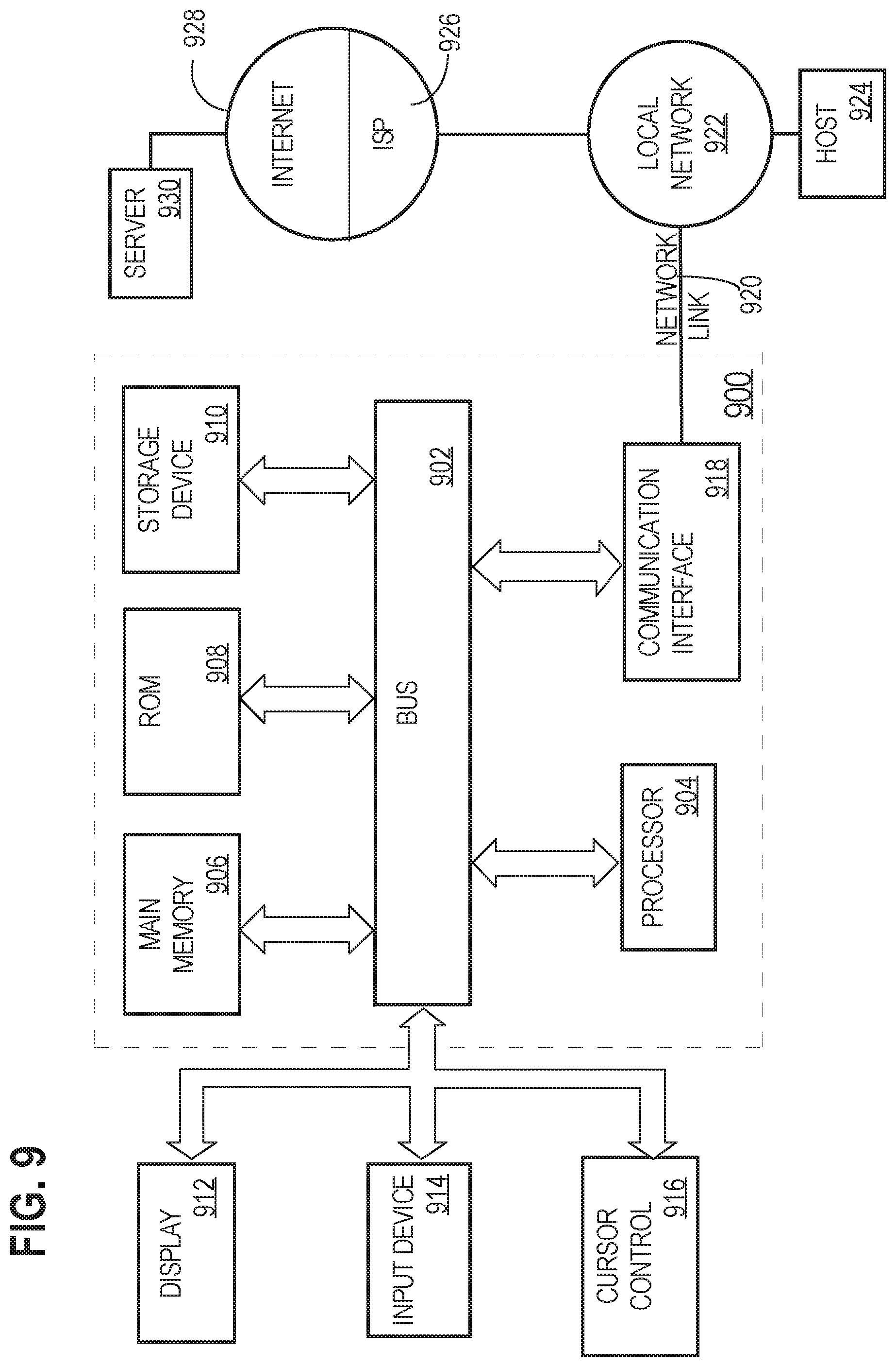
FIG. 9 illustrates an example computer system that may be specially configured to perform various techniques described herein.
DETAILED DESCRIPTION
In the following description, for the purposes of explanation, numerous specific details are set forth in order to provide a thorough understanding of the present disclosure. It will be apparent, however, that embodiments may be practiced without these specific details. In other instances, well-known structures and devices are shown in block diagram form in order to avoid unnecessarily obscuring the present disclosure. Embodiments are described according to the following outline: 1. GENERAL OVERVIEW 2. EXAMPLE MONITORING DEVICE 3. NOISE REDUCTION THROUGH OTHER PPG SIGNALS 4. MULTIPLE EMITTERS WITH SPACING 5. OTHER ARRANGEMENTS OF LIGHT SOURCES AND/OR DETECTORS 6. IMPLEMENTATION EXAMPLE--HARDWARE OVERVIEW
1. General Overview
In one embodiment, a method for creating a blood oxygen saturation (SpO.sub.2) value, the method comprises receiving one or more photoplethysmography (PPG) signals for SpO.sub.2 detection from one or more PPG sensors; receiving one or more PPG signals for characterizing a heart rate from the one or more PPG sensors; using the one or more PPG signals for SpO.sub.2 detection, forming one or more SpO.sub.2 datasets wherein the SpO.sub.2 datasets respectively comprise one or more noise components; removing the one or more noise components from the one or more SpO.sub.2 datasets that are inconsistent with a feature of the one or more PPG signals characterizing the heart rate to produce one or more filtered SpO.sub.2 datasets; and using the one or more filtered SpO.sub.2 datasets, creating and storing the SpO.sub.2 value.
In another embodiment, a monitoring device for creating a SpO.sub.2 value comprises one or more processors coupled to electronic digital memory; in the memory, instructions which when executed by the one or more processors cause the one or more processors to perform: receive one or more PPG signals for SpO.sub.2 detection from one or more PPG sensors; receive one or more PPG signals for characterizing a heart rate from the one or more PPG sensors; use the one or more PPG signals for SpO.sub.2 detection, forming one or more SpO.sub.2 datasets wherein the SpO.sub.2 datasets respectively comprise one or more noise components; remove the one or more noise components from the one or more SpO.sub.2 datasets that are inconsistent with a feature of the one or more PPG signals characterizing the heart rate, to produce one or more filtered SpO.sub.2 datasets; and using the one or more filtered SpO.sub.2 datasets, creating and storing a SpO.sub.2 value.
In yet another embodiment, a data processing method comprises activating one or more first light sources from one or more PPG sensors; receiving one or more first PPG signals for SpO.sub.2 detection from the one or more PPG sensors; determining that a quality of the one or more first PPG signals for SpO.sub.2 detection is below a stored minimum signal value; based on the determining, activating one or more second light sources from the one or more PPG sensors; receiving one or more second PPG signals for SpO.sub.2 detection from the one or more PPG sensors; and using the one or more second PPG signals, creating and storing a SpO.sub.2 value.
In a further embodiment, a monitoring device comprises one or more processors coupled to electronic digital memory; and in the memory, instructions which when executed by the one or more processors cause the one or more processors to: activate one or more first light sources of a plurality of spaced apart light sources, receive one or more first PPG signals for blood oxygen saturation SpO.sub.2 detection from one or more PPG sensors, determine that a quality of the one or more first PPG signals for SpO.sub.2 detection is below a stored minimum signal value, based on the determining, activate one or more second light sources of the plurality of spaced apart light sources, receive one or more second PPG signals for SpO.sub.2 detection from the one or more PPG sensors, determine that a quality of the one or more second PPG signals for SpO.sub.2 detection is above the stored minimum signal value, and using the one or more second PPG signals, create and store a SpO.sub.2 value.
In yet another embodiment, a monitoring device comprises an electronic digital microprocessor coupled to electronic digital memory; one or more detectors on a substrate and coupled to the microprocessor; one or more pairs of light sources that are laterally aligned on the substrate with respect to the one or more detectors; and one or more light sources that are longitudinally aligned on the substrate with respect to the one or more detectors.
In some embodiments, the execution of the method is performed using a monitoring device. Depending on embodiment, the monitoring device can be worn on a wrist (e.g., watch, band), finger (e.g., ring, clip), around a torso (e.g., chest strap), leg, head (e.g., clip on ear, headband, eye wear, and the like), or any other body part. In other embodiments, the techniques described herein may be performed using a server computer, desktop computer, or other computer that is not wearable, in which the computer receives a dataset and performs filtering and other processing operations as further described.
Various other aspects and features of different embodiments will become apparent from the description, drawings and claims.
2. Example Monitoring Device
FIG. 1 illustrates an example monitoring device in relation to a human hand. FIG. 2 illustrates an example hardware architecture of the monitoring device of FIG. 1, FIG. 5. FIG. 5 illustrates a perspective view of a monitoring device, in accordance with one example. For purposes of illustrating a clear example, FIG. 1 and other aspects of this disclosure describe a monitoring device that is configured for wearing on the wrist, but other embodiments may be implemented using monitoring devices that are wearable in other anatomical locations such as the fingertips, ankle, neck, upper arm, torso, leg and/or forehead.
In an embodiment, a monitoring device 100 comprises one or more pairs of light sources 102, one or more secondary light sources 104 and one or more detectors 106. For purposes of illustrating a clear example, FIG. 1 depicts light sources 102, 104 and detectors 106 in an enlarged form, and in practical embodiments, these elements may be implemented using miniature components that are smaller than shown in FIG. 1. In practice, the light sources 102, 104 are positioned to permit the detector 106 to detect reflected light that is emitted from the light sources toward the skin and therefore the light sources and detector may be closely located on a miniature substrate within a housing, band or other protective elements of the monitoring device 100.
As seen in FIG. 2, the monitoring device 100 may further comprise a central processing unit (CPU) 110 coupled to a memory 112, display 114, bus 116, and one or more input/output (I/O) devices 120, and a wireless networking interface 124. Display 114 and/or I/O devices 120 may be omitted in certain embodiments. Display 114 may comprise a liquid crystal display, light-emitting diode display, touchscreen, or other electronic digital display device that a CPU can drive. Display 114 may be programmed or configured to display data, such as time, heart rate, and SpO.sub.2 levels of a user. In an embodiment, the monitoring device 100 is a wristband and the display 114 is configured such that the display faces away from the outside of a user's wrist when the user wears the monitoring device. In other embodiments, the display 114 may be omitted and data detected by the monitoring device 100 may be transmitted using the wireless networking interface 124 via near-field communication (NFC), BLUETOOTH, WiFi, or other suitable wireless communication protocols to a host computer 900 for analysis, display and/or reporting.
I/O devices 120 may include, for example, motion sensors, vibration devices, lights, loudspeakers or sound devices, microphones, or other analog or digital input or output devices. Memory 112 may comprise RAM, ROM, FLASH memory or other digital data storage, and may include a control program 118 comprising sequences of instructions which when loaded from the memory and executed using the CPU 110 cause the CPU to perform the functions that are described herein. The light sources 102, 104 and detectors 106 may be coupled to bus 116 directly or indirectly using driver circuitry by which the CPU may drive the light sources and obtain signals from the detectors.
The host computer 900 may be coupled to the wireless networking interface 124 via one or more networks 128, which may include one or more local area networks, wide area networks, and/or internetworks using any of terrestrial or satellite links. In some embodiments, host computer 900 executes control programs and/or application programs that are configured to perform some of the functions described herein including but not limited to the processes described herein with respect to FIG. 6, FIG. 8.
Further, for purposes of illustrating a clear example, FIG. 1 depicts six pairs of light sources 102, two secondary light sources 104, and one detector 106, but in other embodiments the monitoring device 100 may contain any number of pairs of light sources 102, secondary light sources 104, and detectors 106.
In an embodiment, light sources 102, 104 and detectors 106 are configured to be aligned proximate to a user's skin when monitoring device 100 is worn. "Proximate" may mean any of slightly separated from, near, adjacent to, or in direct contact with, but direct contact is not required. For example, in FIG. 1, monitoring device 100 is worn on the wrist of a user such that light sources 102, 104 and detectors 106 are adjacent to the inner wrist of the user. The positioning of the monitoring device 100 as shown in FIG. 1 is provided merely as an example, and other embodiments may use alternative positioning. For example, the device may be positioned where light sources 102, 104 and detectors 106 are oriented on the outer wrist rather than the inner wrist. The monitoring device 100 may be formed with perimeter dimensions of different sizes that cause the light sources 102, 104 and detectors 106 to be in contact with the skin, or separated from the skin.
FIG. 5 illustrates a schematic perspective view of a monitoring device in one embodiment. In this embodiment, monitoring device 100 comprises a wrist band in which light sources 102, 104 and detectors 106 are mounted on or within an underside of monitoring device 100. Monitoring device 100 may include a fastening means to attach monitoring device to a portion of a user's body and the specific form of the fastening means is not critical. The fastening means may be a strap that is passed through a receiving portion of the strap and fastened with hook and/or loop fasteners. Other fastening means may include clips, latches, hook-and-loop fasteners such as VELCRO, clasps, ties, pegs, and/or adhesives. The fastening means may be located on any side of monitoring device 100 such that the fastening device does not interfere with movement or activity.
In an embodiment, the monitoring device 100 may comprise a processor, memory, user interface, wireless transceiver, one or more environmental sensors, and one or more biometric sensors other than the detectors 106. For example, embodiments may be implemented using a monitoring device of the type shown in U.S. Pat. No. 8,948,832 of Fitbit, Inc., San Francisco, Calif., the entire contents of which are hereby incorporated by reference for all purposes as if fully set forth herein. In other words, the monitoring device of the type shown in U.S. Pat. No. 8,948,832 could be modified based upon the additional disclosure herein to result in a working activity monitoring apparatus capable of performing the functions that are described herein. Therefore, the present disclosure presumes that the reader knows and understands U.S. Pat. No. 8,948,832, and this disclosure is directed to persons having a level of skill sufficient to modify or adapt the monitoring device of the type shown in U.S. Pat. No. 8,948,832 based upon the additional disclosure herein to result in a working activity monitoring apparatus capable of performing the functions that are described herein.
In an embodiment, the light sources 102 may comprise one or more pairs of electronic semiconductor light sources, such as light-emitting diodes (LEDs), which are laterally aligned on a substrate with detectors 106. For example, FIG. 1 and FIG. 5 depict three pairs of light sources 102 on either side of detectors 106. Light sources 102, 104 may be coupled to a power source or driver circuit.
In an embodiment, each pair of light sources 102 includes a red light source and an infrared light source. The light sources 102 may emit light with peak wavelengths typically in the range of 650 nm to 940 nm. For example, in various embodiments a particular red light source may emit light with a peak wavelength of 660 nm. The infrared light source may emit light with peak wavelengths in the range of 750 nm to 1700 nm. By way of example and not limitation, a particular infrared light source may emit light with a peak wavelength of 730 nm, 760 nm, 850 nm, 870 nm, or 940 nm. Commercial light sources such as LEDs tend to provide output at about 20 nm intervals with a center wavelength tolerance of +/-10 nm from the manufacturer's specified wavelength and thus one possible range of useful peak wavelengths for the light sources is 650 nm to 950 nm.
In an embodiment, the light sources 102 are mounted in positions that are spaced apart along the substrate. Pairs of light sources on one side of detectors 106 may be equally spaced from detectors 106 as corresponding pairs on an opposite side of detectors 106. Additionally and/or alternatively, pairs of light sources may be equally spaced from each other. For example, on one side of detectors 106, a first pair of light sources may be placed 1 mm from the detectors; a second pair of light sources may be placed 1 mm from the first light sources; and a third pair of light sources may be placed 1 mm from the second pair of light sources.
The spacing of the light sources may be measured from the side of the light source or the center of the light source. For example, the light sources may be configured such that the center of each light source of a first pair of light sources is 2 mm from the edge of detectors 106 and the center of each light source of a second pair of light sources is 2 mm from the center of a corresponding light source in the first pair of light sources. The particular magnitude of the spacing may depend on a number of factors and this disclosure does not limit the embodiments to any particular spacing. For example, spacing in a range of 1 mm (or less) to 10 mm would be workable in various embodiments.
The orientation of the light sources on either side of detectors 106 may be the same. For example, in the orientation depicted in FIG. 5, each pair of light sources may comprise a top light source comprising a red LED and a bottom light source comprising an infrared LED. In other embodiments, light sources on either side of detectors 106 may have opposite orientations. For example, FIG. 5 depicts light sources on one side of detectors 106 which comprise a top light source comprising a red LED while the light sources on the opposite side of detectors 106 comprise a top light source comprising an infrared LED.
Additionally and/or alternatively, light sources on one side of detectors 106 may have different orientations. For example, a first pair of light sources on one side of detectors 106 may comprise a top light source comprising a red LED and a second light source on the same side of detectors 106 may comprise a top light source comprising an infrared LED.
In an embodiment, light sources 104 may comprise one or more light sources that are longitudinally aligned on a fixed substrate with detectors 106. For example, FIG. 1 and FIG. 5 depict two light sources 104, one which is above the detectors 106 and one which is below the detectors 106. In an embodiment, light sources 104 may be green light sources, such as green LEDs. The green light sources may be configured to emit light with wavelengths in the range of 495 nm to 570 nm. For example, a particular green light source may emit light with a wavelength of 528 nm. The green light sources may be equally spaced from detectors 106 as the pairs of red and infrared light sources. For example, if the distance between detectors 106 and a center of a first red light source is 2 mm, the distance between detectors 106 and a green light source may also be 2 mm. Further, in some embodiments, one or more of the light sources 104 may comprise a single LED package that emits multiple wavelengths, such as green, red and infrared wavelengths, at the same location with respect to multiple detectors. Such LEDs may include multiple semiconductor elements co-located using a single die in a single packages, and therefore FIG. 1, FIG. 5 are not intended to imply that separate components in separate packages are required.
Detectors 106 are sensors adapted to detect wavelengths of light emitted from light sources 102, 104 and together with the light sources form sensors such as PPG sensors. A particular light source 102 combined with a particular detector 106 may comprise a sensor such as a PPG sensor. A first PPG sensor and a second PPG sensor can share components, such as the same light sources and/or detectors, or have different components and thus the term "PPG sensor" is used for simplicity of description although actual embodiments may use multiple components in implementing a PPG sensor. Detectors 106, in an embodiment, may comprise one or more detectors for detecting each different wavelength of light that is used by the light sources. For example, a first detector may be configured to detect light with a wavelength of 660 nm, a second detector may be configured to detect light with a wavelength of 940 nm, and a third detector may be configured to detect light with a wavelength of 528 nm. Examples include photodiodes fabricated from semiconductor materials and having optical filters that admit only light of a particular wavelength or range of wavelengths.
In other embodiments, detectors 106 comprise one or more detectors configured to detect multiple wavelengths of light. For example, a single detector may be configured to tune to different frequencies based on data received from an electrical digital microprocessor coupled to detectors 106. In another way, the single detector may include multiple active areas where each active area is sensitive to a given range of wavelengths. In an embodiment, a single detector is configured to detect light with wavelengths in the red and infrared frequencies and a second detector is configured to detect light with wavelengths in the green frequencies. Further, each of the light sources 102, 104 may use any of one or more different wavelengths of light as previously described.
In an embodiment, detectors 106 are mounted in a housing with one or more filters configured to filter out wavelengths of light other than wavelengths emitted by light sources 102, 104. For example, a first portion of the housing may be covered with a filter which removes ambient light other than light in wavelengths emitted by light sources 102 and a second portion of the housing may be covered with a filter which removes all ambient light other than light in wavelengths emitted by light sources 104. For example, signals from one or more PPG sensors may be received through an ambient light filter that filters out an ambient light source that generates an ambient light with a wavelength that is different from the wavelength that is detected by at least one of the sensors.
FIG. 4 illustrates an example topology of a light source and a plurality of detectors (e.g., photodiodes). FIG. 4 is shown in simplified, schematic format for purposes of illustrating a clear example. In an embodiment, a multi-color light-emitting diode (LED) 186 is affixed to a substrate within the monitoring device 100. A first photodiode 180 is located in a position on a first light path with respect to LED 186. Second and third photodiodes 182, 184 are located symmetrically opposite the LED and are aligned on light paths that are different from the first light path. In one embodiment, LED 186 is capable of emitting three (3) wavelengths of light in the red, infrared, and green portions of the spectrum, using multiple semiconductor devices within a single lens or package. The first photodiode 180 is configured to receive PPG signals based upon emission of red and infrared light and is used to produce a SpO.sub.2 signal. The second and third photodiodes 182, 184 are configured to detect PPG signals based upon emission of green light and to generate a heart rate signal based on those PPG signals. The SpO.sub.2 signal and heart rate signal may be processed in the manner that is described herein, for example, with respect to the flow diagrams and other functional descriptions.
3. Noise Reduction Through Other PPG Signals
A number of flow diagrams are presented herein to illustrate various methods that may be performed by example embodiments. The flow diagrams illustrate example algorithms that may be programmed, using any suitable programming environment or language, to create machine code capable of execution by a CPU or microcontroller of the monitoring device 100. In other words, the flow diagrams, together with the written description in this document, are disclosures of algorithms for aspects of the claimed subject matter, presented at the same level of detail that is normally used for communication of this subject matter among skilled persons in the art to which the disclosure pertains. Various embodiments may be coded using assembly, C, OBJECTIVE-C, C++, JAVA, or other human-readable languages and then compiled, assembled, or otherwise transformed into machine code that can be loaded into ROM, EPROM, or other recordable memory of the activity monitoring apparatus that is coupled to the CPU or microcontroller and then executed by the CPU or microcontroller.
For purposes of illustrating a clear example, this disclosure may describe the methods with reference to the devices/components shown in other figures, such as FIGS. 1 and 2. However, other embodiments may be implemented using data from other sources and computers or apparatus other than those shown in the aforementioned figures.
To begin, FIG. 3 illustrates an example method for creating a SpO.sub.2 value using a PPG signal as a reference signal to filter PPG signals used to determine the SpO.sub.2 value.
The method shown in FIG. 3 may begin at block 350 when a monitoring device receives a first set of one or more PPG signals from one or more PPG sensors. The first set of PPG signals may be represented in any suitable form capable of being processed by a processor, such as the analog signals or digital data sampled from the analog components and stored in computer memory. In an example, the first set of PPG signals may correspond to red and/or infrared light previously emitted by a light source (or light sources) after the emitted light has interacted with a user's skin, when the monitoring device is worn. It is to be appreciated that the first set of PPG signals may include a noise component, as discussed above.
The method shown in FIG. 3 may continue at block 352 when the monitoring device receives a second set of one or more PPG signals from the one or more PPG sensors. Again, the second set of PPG signals may be represented in any suitable form capable of being processed by a processor, such as the analog signals or digital data sampled from the analog components and stored in computer memory. In an example, the second set of PPG signals is obtained from different ranges of wavelengths emitted from the light source than the first set of PPG signals. For example, the second set of PPG signals may be obtained from green light sources. In some cases, the second set of PPG signals is obtained from a system within the monitoring device used for tracking a user's heart rate. In other cases, the second set of PPG signals is received from a system separate from heart rate detection.
At block 354, the monitoring device filters the first set of PPG signals based on a feature of the second set of PPG signals to generate a filtered set of PPG signals. Various filtering techniques may be used, depending on embodiment, to remove noise or other features from the first set of PPG signals based on a feature of the second set of PPG signals. As one example, heart rate may be the feature of the second set of PPG signals. In the case of a heart rate, the monitoring device may create a filter based the detected frequency of the heart rate signal. Examples of filters include a low-pass filter, a high-pass filter, and a narrow band filter that excludes frequencies that are inconsistent with the frequency of the heart rate signal.
It is to be appreciated that, based on block 354, the monitoring device may use one range of wavelengths to better measure an underlying signal on which the wavelengths of the first set of PPG signals operates. Based on this underlying signal (or features derived therefrom), the monitoring device can improve the first set of PPG signals based on filtering noise from the first set of PPG signals.
Continuing with the method shown in FIG. 3, at block 356, the monitoring device may use the filtered set of PPG signals to create and store a SpO.sub.2 value. As an example, the filtered set of PPG signals may have a reduced or eliminated noise component and therefore may serve as a more accurate basis for creating and storing the SpO.sub.2 value.
Accordingly, the method shown in FIG. 3 illustrates a method for using a first set of PPG signals to detect an underlying signal to improve another set of PPG signals that may be used to determine a SpO.sub.2 value. Alternative or specific embodiments are now discussed.
FIG. 6 illustrates a flow diagram of another method for creating and storing a SpO.sub.2 value using PPG signals for SpO.sub.2 and PPG signals for characterizing or determining a heart rate.
At step 602, one or more PPG signals for SpO.sub.2 detection are received from one or more PPG sensors. For example, power from a power supply, such as a battery and power supply circuit, is coupled to red and infrared light sources 102, which are energized and, when the monitoring device is worn, produce light toward the skin that is proximate to blood vessels. Reflected light is detected using the detector 106 and PPG signals are formed using the detector 106 and gated or signaled for transient storage in memory within the monitoring device 100. Under program control, the CPU or microcontroller may load a set of PPG signals from the memory into registers or other data storage. The PPG signals may be obtained from the detectors based upon light sources operating at any of the frequencies that have been described above with respect to FIG. 1, FIG. 5.
At step 604, one or more PPG signals for characterizing a heart rate are received from the one or more PPG sensors. Step 604 may be implemented in the manner described above for step 602, except that, in some cases, the green light sources 104 are used and the PPG signals for characterizing a heart rate are formed based upon reflected green light that is detected using the detectors 106. The PPG signals for characterizing the heart rate may, in some cases, be suitable to represent an underlying signal from the PPG sensors. However, compared to the PPG signals for SpO.sub.2 detection, the PPG signals for characterizing the heart rate may be obtained from a wavelength that better exhibits the underlying signal. In some cases, the PPG signals for characterizing a heart rate may be based upon detection of reflected green light from the green light sources. The PPG signals for characterizing the heart rate may characterize the heart rate in that one or more of the following features may be determinable: a fundamental frequency (e.g., of the green light), one or more different harmonic frequencies (e.g., of the green light), a template of the underlying signal (e.g., the green light), and the like.
As an alternative to using the green PPG signal from the monitoring device 100, a signal characteristic of a heart rate may be obtained from an entirely different apparatus, such as from an electrocardiogram (EKG) apparatus in real time, or from stored EKG data that is obtained from a server computer by direct retrieval from storage that is coupled to the server computer, or programmatically using an application program interface (API) call, or using any other suitable data retrieval operation. In other words, the heart rate signal that is used in adaptively filtering the red and infrared PPG signals need not come from the activity monitoring apparatus, and need not be received at the same time as the red and infrared signals; instead any other source of the heart rate signal may be used.
In some embodiments, the PPG signals for SpO.sub.2 and heart rate may be correlated in time by interlacing or another form of multiplexing, and stored in that format. Thus various embodiments may store separate streams of PPG signal data for heart rate and SpO.sub.2 or an integrated stream in which both kinds of data are interleaved or mixed. In some embodiments, the PPG signals that are used for determining characteristics of heart rate may be obtained from a system that measures a user's heart rate and is separate from the systems described herein. Such an embodiment may contribute PPG signals to the system disclosed herein, and those contributed signals then may be improved based upon the PPG signals for SpO.sub.2 that are obtained using the system disclosed herein. For example, a medical-grade fingertip pulse oximetry device could be used to acquire PPG signals indicating pulse, and those signals may be received at a server computer that also obtains PPG signals for SpO.sub.2 in the manner described herein. The server computer may be programmed to implement the noise removal and other signal improvement techniques described herein.
At step 606, one or more SpO.sub.2 datasets are formed where the SpO.sub.2 includes one or more noise components, using the one or more PPG signals for SpO.sub.2 detection that have been obtained or received from detectors in any of the topologies for light sensors and detectors that are described herein. In an embodiment, under program control, the PPG signals that were received at step 602 are stored as SpO.sub.2 datasets in digital memory. A "dataset," as used herein, may refer to a computer usable representation of data stored in computer memory. The dataset may be organized or otherwise structured to allow for a processor or program to access given elements of the datasets, such as an indexed (e.g., the Nth) sample of the PPG signal. In an example, the dataset may be stored in a buffer used for temporary processing or storing or in computer memory used for longer-term processing or storage.
In many cases, the PPG signals for SpO.sub.2 and the corresponding SpO.sub.2 datasets include a noise component. Noise may be introduced into a PPG signal, for example, from skin morphology of the wearer of the apparatus, the presence of hair, tattoos, fatty tissue, pathological conditions that result in weak blood circulation, movement of the device, or other conditions.
At step 608, the noise components are removed from the one or more SpO.sub.2 datasets to produce one or more filtered SpO.sub.2 datasets, which can be performed by using an adaptive filter for which the one or more SpO.sub.2 datasets and a characteristic of the one or more PPG signals for characterizing a heart rate are inputs. For example, the SpO.sub.2 datasets formed at step 606 may be filtered based upon the signals received at step 604 to remove all or part of noise components from the SpO.sub.2 datasets to yield filtered SpO.sub.2 datasets. In one embodiment, the PPG signals obtained using infrared and red light sources typically are weaker than signals based upon green light sources (e.g., see FIG. 7); however, a heart rate signal determined using the green light source may be used to improve the PPG signals with an adaptive filter that uses the heart rate information detected using the green light sources to remove noise that are inconsistent with the heart rate frequency. In an embodiment, the PPG signals for SpO.sub.2 comprise primary inputs to an adaptive filter and the heart rate signal is the reference input.
With respect to the operation of removing the noise components, various embodiments may use least mean squares (LMS) filtering of the one or more SpO.sub.2 datasets with the one or more PPG signals for heart rate, recursive least squares (RLS) filtering, and similar techniques, implemented in executable code in the monitoring device 100 or in host computer 900 that is processing data received from the monitoring device. Other example techniques include creating a template from a high-quality PPG signal to use as filter coefficients for a matched filter to maximize signal to noise in the presence of additive, stochastic noise. Yet another technique is using an adaptive filter that tunes a band-pass in real-time based upon heartbeat data derived from the PPG datasets, usually based upon green light sources. Correlation computations may be computed between SpO.sub.2 datasets obtained from red or infrared light sources and PPG signals obtained from green light sources, to identify motion artifacts. Thus one embodiment may comprise using the adaptive filter with one or more SpO.sub.2 datasets and a feature of the one or more PPG signals for characterizing a heart rate as inputs, and removing the noise components from the one or more SpO.sub.2 datasets, that are inconsistent with a characteristic of the heart rate frequency PPG signal, to produce one or more filtered SpO.sub.2 datasets as output, using a least mean squares fitting or recursive least squares fitting of the one or more SpO.sub.2 datasets to the heart rate frequency PPG signal.
The utility of step 608 may be further understood with reference to FIG. 7. FIG. 7 is a two-part graph that illustrates example PPG signals before and after removal of noise based upon a heart rate information. A first graph at the top of FIG. 7 depicts lines representing green, red, and infrared PPG signals obtained from detection of reflected light from green, red, and infrared light sources respectively, illustrated as amplitude versus time. It will be seen that the red and infrared signals include significant noise components expressed as repeated short changes in amplitude over a given time span. The green signal exhibits a sharp upward peak, and the peak-to-peak distance may be used to determine a likely true heart rate frequency of the subject. An adaptive filter, tuned to the heart rate frequency, may be used to smooth or remove noise that is located around the peak points of the green signal when superimposed on the red and infrared signals. As seen in the second graph at the top of FIG. 7, this form of filtering results in outputting a filtered red PPG signal and a filtered infrared PPG signal that are smoother and therefore more accurate in indicating SpO.sub.2 data.
With reference back to FIG. 6, at step 610, an SpO.sub.2 value is created and stored using the one or more filtered SpO.sub.2 datasets; the resulting value may be stored in memory of the monitoring device 100 or the host computer 900. An "SpO.sub.2 value," as used herein, may refer to a metric that estimates a user's SpO.sub.2 level or changes in the user's SpO.sub.2 level. Thus some embodiments may generate metrics representing absolute SpO.sub.2 values or relative changes in SpO.sub.2.
The result of the method 600 can be a more accurate SpO.sub.2 value. Further, the infrared and red light PPG signals may be processed with more robustness to noise, and therefore the monitoring device 100 may be designed or engineered to accommodate less strict noise floor requirements. For example, the monitoring device may be, in some cases, capable of accommodating a less snug attachment to the body, and/or the monitoring device may, in some cases, be capable of accommodating hair and skin conditions, or other noise sources that can interfere with the monitoring device when mounted on the body.
It is to be appreciated that the method 600 may be performed by one or more of: firmware operating on the monitoring device or a secondary device (e.g., a mobile device paired to the monitoring device, a server, or the like). For example, the monitoring device may execute operations relating to generating the PPG signals (for SpO.sub.2 detection and for characterizing a heart rate), which, in turn, are uploaded or otherwise communicated to a server that performs operations for removing the noise data sets and creating the SpO.sub.2 value. Alternatively, the monitoring device may execute operations relating to generating the PPG signals (for SpO.sub.2 detection and for characterizing a heart rate) and removing the noise data sets to produce the filtered SpO.sub.2 datasets. In this case, the filtered SpO.sub.2 datasets are uploaded or otherwise communicated to a server that performs operations for creating the SpO.sub.2 value. As another alternative, the monitoring device may execute each operation described with reference to the method 600 shown in FIG. 6.
4. Multiple Emitters with Spacing
In an embodiment, the use of multiple light sources or other emitters in configurations that are spaced differently with respect to the detector permits the monitoring device 100 to control the effective detector-emitter spacing to optimize for signal strength under various user skin conditions, by activating different pairs of red and infrared emitters. As the detector-emitter spacing increases, for example, a light path between the emitter and detector samples tissue content over a longer and deeper path, thereby improving signal strength. For example, users who exhibit periods of time of low perfusion, due to conditions such as cooling of the skin, may benefit from increasing the emitter-detector spacing automatically under program control, by activating the red light sources and infrared light sources that are farther away from the detector. The same effect can be obtained using a single emitter and a plurality of detectors.
FIG. 8 illustrates a flow diagram of a method for creating and storing a SpO.sub.2 value using a plurality of spaced apart light sources.
At step 802, one or more first light sources of a plurality of spaced apart light sources are activated. For example, step 802 may comprise using the CPU to signal a display driver circuit to energize a first pair of red and infrared light sources in the monitoring device 100.
At step 804, one or more first PPG signals for SpO.sub.2 detection are received from one or more PPG sensors. Step 804 may comprise operations similar to those described above for step 602 (FIG. 6).
At step 806, a quality of a particular PPG signal of the one or more first PPG signals for SpO.sub.2 detection is determined to be below a stored minimum signal value. Step 806 may comprise the CPU 110 (FIG. 2) comparing a stored threshold value, which represents a minimum acceptable signal value, to the amplitude of the PPG signals received at step 804.
At step 808, based on determining that the quality of the particular PPG signal is below the stored minimum signal value, one or more second light sources of the plurality of spaced apart light sources are activated. For example, step 808 may comprise the CPU signaling the display driver circuit to energize a second pair of red and infrared light sources at a different second position from the first pair.
Further, using these techniques, an embodiment of FIG. 8 may comprise: activating only a first pair of two or more pairs of light sources, and deactivating one or more other pairs; receiving, from one or more detectors, a first red PPG signal and a first infrared PPG signal from only the first pair of two or more pairs of red light sources and infrared light sources; determining that a first red PPG signal quality is below a stored minimum red PPG signal value or that a first infrared PPG signal quality is below a stored minimum infrared PPG signal value; and based on the determining, activating a second pair of the two or more pairs of red light sources and infrared light sources, receiving from the one or more detectors a second red PPG signal and a second infrared PPG signal associated with the second pair; determining that a second red PPG signal quality is above the stored minimum red PPG signal value and that the second infrared PPG signal quality is above the stored minimum infrared PPG signal quality value; using the second red PPG signal and the second infrared PPG signal as the one or more PPG signals for SpO.sub.2 detection, determining one or more SpO.sub.2 datasets. In some embodiments, the first signals that were used for quality determination are discarded or deleted from memory in favor of using the second signals, but this step is not required in all embodiments.
At step 810, one or more second PPG signals for SpO.sub.2 detection are received from the one or more PPG sensors. Step 810 may comprise obtaining signals from the second pair of light sources as well as the first pair of light sources. At step 812, a quality of the one or more second PPG signals for SpO.sub.2 is determined to be above the stored minimum signal value. At step 814, a SpO.sub.2 value is created and stored using the one or more second PPG signals.
Additionally or alternatively, the process of FIG. 8 may receive input from biometric sensors or environmental sensors indicating an ambient temperature or a skin temperature of the wearer of the activity monitoring apparatus. Based on changes in temperature values received from these sensors, the process may energize or de-energize different pairs of light sources. In this embodiment, the process of FIG. 8 may include: activating only a first pair of two or more pairs of red light sources and infrared light sources, and deactivating all other pairs; receiving, from the one or more detectors, a first red PPG signal and a first infrared PPG signal from only the first pair of the two or more pairs of red light sources and infrared light sources; receiving an ambient temperature signal from an ambient temperature sensor that is located proximate to the two or more first pairs; determining that the ambient temperature signal is less than a stored minimum temperature signal; based on the determining, activating a second pair of the two or more pairs of red light sources and infrared light sources, receiving from the one or more detectors a second red PPG signal and a second infrared PPG signal associated with the second pair, forming a combined red PPG signal using the first red PPG signal and the second red PPG signal, and forming a combined infrared PPG signal using the first infrared PPG signal and the second infrared PPG signal.
The process of FIG. 8 may include a feedback loop and other test operations that result in selectively energizing or de-energizing different pairs of red and infrared light sources of the monitoring device 100 as ambient conditions change. For example, the process of FIG. 8 may be implemented as part of a continuous loop that is active whenever the monitoring device 100 is powered on, and may include operations to de-energize the second pair of light sources when signals received from the first pair of light sources are determined to be greater than the stored minimum signal value. Further, the process as a whole may be repeated for any one or more pairs of the light sources, so that the process results in energizing three or more pairs of light sources at any one time. In this manner, over time, different combinations of pairs may be energized or de-energized dynamically in response to changing ambient conditions, changing skin temperature, movement of the monitoring device 100 on the body of the user, or other conditions that result in changes in the strength of signals from the light sources.
5. Other Arrangements of Light Sources and/or Detectors
In an embodiment, light sources 102 are positioned on a rotatable substrate proximate to detectors 106. The rotatable substrate may be communicatively coupled to an electrical digital microprocessor and configured to alter a position of one or more pairs of light sources 102. The rotatable substrate may move pairs of light sources 102 laterally or may rotate pairs of light sources 102 around an axis. For example, FIG. 5 depicts three pairs of light sources 102 on either side of detectors 106. The rotatable substrate may be configured to shift a single pair of light sources 102 to the different positions depicted in FIG. 5. As another example, the rotatable substrate may be configured to flip the positions of each light source of a pair of light sources, such that a red light sources switches positions with an infrared light source.
The rotatable substrate may comprise a flat disk formed of metal or plastic that is affixed to a driving mechanism that is operable under control of the processor using a geared mechanism, or using electromagnetic means. For example, two or more points spaced apart around the circumference or perimeter of the substrate may comprise fixed rare earth magnets and the processor may be coupled to a single electromagnetic coil that may be energized at a first polarity or second polarity, which induces within the coil a magnetic field of a first polar orientation or a second polar orientation; using this means one of the magnets on the rotatable substrate will be alternatively attracted to or repelled from the coil, resulting in rotated or lateral motion of the substrate to an opposite circumferential position.
In an embodiment, a plurality of the light sources 102 may be positioned around one or more detectors, on a planar substrate that is circular or having other geometry, at different fixed angles with respect to one or more detectors at a center of the substrate or arranged at different angles around the substrate near the light sources. The light sources may be single-color, arranged in pairs such as red-infrared, red-green, or infrared-green. In this arrangement, the control program 118 may be programmed to selectively drive different light sources at different angular positions with respect to the detectors, and to test the quality of data resulting from driving those light sources. For example, the control program 118 may be configured to iterate through a plurality of different combinations of angular positions of light sources, while testing the amplitude of signals obtained via each combination, and to select a particular combination of light sources that is providing the signals of greatest amplitude. In this manner, over time, different combinations of light sources or pairs may be energized or de-energized dynamically in response to changing ambient conditions, changing skin temperature, movement of the monitoring device 100 on the body of the user, or other conditions that result in changes in the strength of signals from the light sources.
In these embodiments, the processes of FIG. 6, FIG. 8 may be implemented with additional operations that drive repositioning the rotatable substrate. For example, referring to FIG. 8, step 808 may comprise using the processor to energize the coil using a first particular polarity, thereby causing the rotatable substrate to rotate other light sources into position.
6. Implementation Example--Hardware Overview
According to one embodiment, the techniques described herein are implemented by one or more special-purpose computing devices. The special-purpose computing devices may be hard-wired to perform the techniques, or may include digital electronic devices such as one or more application-specific integrated circuits (ASICs) or field programmable gate arrays (FPGAs) that are persistently programmed to perform the techniques, or may include one or more general purpose hardware processors programmed to perform the techniques pursuant to program instructions in firmware, memory, other storage, or a combination. Such special-purpose computing devices may also combine custom hard-wired logic, ASICs, or FPGAs with custom programming to accomplish the techniques. The special-purpose computing devices may be desktop computer systems, portable computer systems, handheld devices, networking devices or any other device that incorporates hard-wired and/or program logic to implement the techniques.
For example, FIG. 9 is a block diagram that illustrates a computer system 900 upon which an embodiment may be implemented. Computer system 900 includes a bus 902 or other communication mechanism for communicating information, and a hardware processor 904 coupled with bus 902 for processing information. Hardware processor 904 may be, for example, a general purpose microprocessor.
Computer system 900 also includes a main memory 906, such as a random access memory (RAM) or other dynamic storage device, coupled to bus 902 for storing information and instructions to be executed by processor 904. Main memory 906 also may be used for storing temporary variables or other intermediate information during execution of instructions to be executed by processor 904. Such instructions, when stored in non-transitory storage media accessible to processor 904, render computer system 900 into a special-purpose machine that is customized to perform the operations specified in the instructions.
Computer system 900 further includes a read only memory (ROM) 908 or other static storage device coupled to bus 902 for storing static information and instructions for processor 904. A storage device 910, such as a magnetic disk, optical disk, or solid-state drive is provided and coupled to bus 902 for storing information and instructions.
Computer system 900 may be coupled via bus 902 to a display 912, such as a cathode ray tube (CRT), for displaying information to a computer user. An input device 914, including alphanumeric and other keys, is coupled to bus 902 for communicating information and command selections to processor 904. Another type of user input device is cursor control 916, such as a mouse, a trackball, or cursor direction keys for communicating direction information and command selections to processor 904 and for controlling cursor movement on display 912. This input device typically has two degrees of freedom in two axes, a first axis (e.g., x) and a second axis (e.g., y), that allows the device to specify positions in a plane.
Computer system 900 may implement the techniques described herein using customized hard-wired logic, one or more ASICs or FPGAs, firmware and/or program logic which in combination with the computer system causes or programs computer system 900 to be a special-purpose machine. According to one embodiment, the techniques herein are performed by computer system 900 in response to processor 904 executing one or more sequences of one or more instructions contained in main memory 906. Such instructions may be read into main memory 906 from another storage medium, such as storage device 910. Execution of the sequences of instructions contained in main memory 906 causes processor 904 to perform the process steps described herein. In alternative embodiments, hard-wired circuitry may be used in place of or in combination with software instructions.
The term "storage media" as used herein refers to any non-transitory media that store data and/or instructions that cause a machine to operate in a specific fashion. Such storage media may comprise non-volatile media and/or volatile media. Non-volatile media includes, for example, optical disks, magnetic disks, or solid-state drives, such as storage device 910. Volatile media includes dynamic memory, such as main memory 906. Common forms of storage media include, for example, a floppy disk, a flexible disk, hard disk, solid-state drive, magnetic tape, or any other magnetic data storage medium, a CD-ROM, any other optical data storage medium, any physical medium with patterns of holes, a RAM, a PROM, and EPROM, a FLASH-EPROM, NVRAM, any other memory chip or cartridge.
Storage media is distinct from but may be used in conjunction with transmission media. Transmission media participates in transferring information between storage media. For example, transmission media includes coaxial cables, copper wire and fiber optics, including the wires that comprise bus 902. Transmission media can also take the form of acoustic or light waves, such as those generated during radio-wave and infra-red data communications.
Various forms of media may be involved in carrying one or more sequences of one or more instructions to processor 904 for execution. For example, the instructions may initially be carried on a magnetic disk or solid-state drive of a remote computer. The remote computer can load the instructions into its dynamic memory and send the instructions over a telephone line using a modem. A modem local to computer system 900 can receive the data on the telephone line and use an infra-red transmitter to convert the data to an infra-red signal. An infra-red detector can receive the data carried in the infra-red signal and appropriate circuitry can place the data on bus 902. Bus 902 carries the data to main memory 906, from which processor 904 retrieves and executes the instructions. The instructions received by main memory 906 may optionally be stored on storage device 910 either before or after execution by processor 904.
Computer system 900 also includes a communication interface 918 coupled to bus 902. Communication interface 918 provides a two-way data communication coupling to a network link 920 that is connected to a local network 922. For example, communication interface 918 may be an integrated services digital network (ISDN) card, cable modem, satellite modem, or a modem to provide a data communication connection to a corresponding type of telephone line. As another example, communication interface 918 may be a local area network (LAN) card to provide a data communication connection to a compatible LAN. Wireless links may also be implemented. In any such implementation, communication interface 918 sends and receives electrical, electromagnetic or optical signals that carry digital data streams representing various types of information.
Network link 920 typically provides data communication through one or more networks to other data devices. For example, network link 920 may provide a connection through local network 922 to another host computer 924 or to data equipment operated by an Internet Service Provider (ISP) 926. ISP 926 in turn provides data communication services through the world wide packet data communication network now commonly referred to as the "Internet" 928. Local network 922 and Internet 928 both use electrical, electromagnetic or optical signals that carry digital data streams. The signals through the various networks and the signals on network link 920 and through communication interface 918, which carry the digital data to and from computer system 900, are example forms of transmission media.
Computer system 900 can send messages and receive data, including program code, through the network(s), network link 920 and communication interface 918. In the Internet example, a server 930 might transmit a requested code for an application program through Internet 928, ISP 926, local network 922 and communication interface 918.
The received code may be executed by processor 904 as it is received, and/or stored in storage device 910, or other non-volatile storage for later execution.
In the foregoing specification, embodiments have been described with reference to numerous specific details that may vary from implementation to implementation. The specification and drawings are, accordingly, to be regarded in an illustrative rather than a restrictive sense. The sole and exclusive indicator of the scope of the disclosure, and what is intended by the applicants to be the scope of the disclosure, is the literal and equivalent scope of the set of claims that issue from this application, in the specific form in which such claims issue, including any subsequent correction.
* * * * *
References
D00000
D00001
D00002
D00003
D00004
D00005
D00006
D00007
D00008
D00009
XML
uspto.report is an independent third-party trademark research tool that is not affiliated, endorsed, or sponsored by the United States Patent and Trademark Office (USPTO) or any other governmental organization. The information provided by uspto.report is based on publicly available data at the time of writing and is intended for informational purposes only.
While we strive to provide accurate and up-to-date information, we do not guarantee the accuracy, completeness, reliability, or suitability of the information displayed on this site. The use of this site is at your own risk. Any reliance you place on such information is therefore strictly at your own risk.
All official trademark data, including owner information, should be verified by visiting the official USPTO website at www.uspto.gov. This site is not intended to replace professional legal advice and should not be used as a substitute for consulting with a legal professional who is knowledgeable about trademark law.