Radially compressible and expandable rotor for a fluid pump
Roehn Feb
U.S. patent number 10,557,475 [Application Number 15/869,285] was granted by the patent office on 2020-02-11 for radially compressible and expandable rotor for a fluid pump. This patent grant is currently assigned to ECP ENTWICKLUNGSGESELLSCHAFT MBH. The grantee listed for this patent is ECP ENTWICKLUNGSGESELLSCHAFT MBH. Invention is credited to Daniel Roehn.
| United States Patent | 10,557,475 |
| Roehn | February 11, 2020 |
Radially compressible and expandable rotor for a fluid pump
Abstract
In a rotor for a fluid pump which is made radially-compressible and expandable and has a hub (4) and at least one conveying element (10, 11, 19, 20) which has a plurality of struts (12, 13, 14, 15, 16, 21, 22, 27, 28) and at least one membrane (18) which can be spanned between them, provision is made for a design in accordance with the invention which is as simple and inexpensive as possible that at least one first group of struts is pivotable in a pivot plane, starting from a common base, and can thus be spanned open in the manner of a fan, wherein the conveying element lies along the hub and contacts it over its full length in the expanded state to avoid a pressure loss at the margin of the conveying element between it and the hub and thus to realize an optimum efficiency.
| Inventors: | Roehn; Daniel (Berlin, DE) | ||||||||||
|---|---|---|---|---|---|---|---|---|---|---|---|
| Applicant: |
|
||||||||||
| Assignee: | ECP ENTWICKLUNGSGESELLSCHAFT
MBH (BerlinAmtsgericht, Berlin, (Charlottenburg),
DE) |
||||||||||
| Family ID: | 42211651 | ||||||||||
| Appl. No.: | 15/869,285 | ||||||||||
| Filed: | January 12, 2018 |
Prior Publication Data
| Document Identifier | Publication Date | |
|---|---|---|
| US 20180135642 A1 | May 17, 2018 | |
Related U.S. Patent Documents
| Application Number | Filing Date | Patent Number | Issue Date | ||
|---|---|---|---|---|---|
| 15142292 | Apr 29, 2016 | 9903384 | |||
| 13261315 | May 17, 2016 | 9339596 | |||
| PCT/EP2010/007996 | Dec 23, 2010 | ||||
| 61289569 | Dec 23, 2009 | ||||
Foreign Application Priority Data
| Dec 23, 2009 [EP] | 09075572 | |||
| Current U.S. Class: | 1/1 |
| Current CPC Class: | F04D 29/247 (20130101); F04D 29/607 (20130101); A61M 1/1024 (20140204); A61M 1/1031 (20140204); A61M 1/125 (20140204); A61M 1/1034 (20140204); A61M 1/101 (20130101); A61M 1/122 (20140204) |
| Current International Class: | F04D 29/24 (20060101); F04D 29/60 (20060101); A61M 1/10 (20060101); A61M 1/12 (20060101) |
| Field of Search: | ;416/87,88,131,132R,132A,142,143,240,241R ;415/900 ;600/16-18 |
References Cited [Referenced By]
U.S. Patent Documents
| 3510229 | May 1970 | Smith et al. |
| 3568659 | March 1971 | Karnegis |
| 3802551 | April 1974 | Somers |
| 3812812 | May 1974 | Hurwitz |
| 4014317 | March 1977 | Bruno |
| 4207028 | June 1980 | Ridder |
| 4559951 | December 1985 | Dahl et al. |
| 4563181 | January 1986 | Wijayarathna et al. |
| 4679558 | July 1987 | Kensey et al. |
| 4686982 | August 1987 | Nash |
| 4747821 | May 1988 | Kensey et al. |
| 4749376 | June 1988 | Kensey et al. |
| 4753221 | June 1988 | Kensey et al. |
| 4801243 | January 1989 | Norton |
| 4817613 | April 1989 | Jaraczewski et al. |
| 4919647 | April 1990 | Nash |
| 4957504 | September 1990 | Chardack |
| 4969865 | November 1990 | Hwang et al. |
| 4995857 | February 1991 | Arnold |
| 5011469 | April 1991 | Buckberg et al. |
| 5040944 | August 1991 | Cook |
| 5042984 | August 1991 | Kensey et al. |
| 5052404 | October 1991 | Hodgson |
| 5061256 | October 1991 | Wampler |
| 5092844 | March 1992 | Schwartz et al. |
| 5097849 | March 1992 | Kensey et al. |
| 5108411 | April 1992 | McKenzie |
| 5112292 | May 1992 | Hwang et al. |
| 5113872 | May 1992 | Jahrmarkt et al. |
| 5117838 | June 1992 | Palmer et al. |
| 5118264 | June 1992 | Smith |
| 5145333 | September 1992 | Smith |
| 5151721 | September 1992 | Allendorf et al. |
| 5163910 | November 1992 | Schwartz et al. |
| 5169378 | December 1992 | Figuera |
| 5183384 | February 1993 | Trumbly |
| 5191888 | March 1993 | Palmer et al. |
| 5201679 | April 1993 | Velte, Jr. et al. |
| 5275580 | January 1994 | Yamazaki |
| 5373619 | December 1994 | Fleischhacker et al. |
| 5376114 | December 1994 | Jarvik |
| 5501574 | March 1996 | Raible |
| 5531789 | July 1996 | Yamazaki et al. |
| 5701911 | December 1997 | Sasamine et al. |
| 5749855 | May 1998 | Reitan |
| 5755784 | May 1998 | Jarvik |
| 5776190 | July 1998 | Jarvik |
| 5813405 | September 1998 | Montano, Jr. et al. |
| 5820571 | October 1998 | Erades et al. |
| 5851174 | December 1998 | Jarvik et al. |
| 5877566 | March 1999 | Chen |
| 5882329 | March 1999 | Patterson et al. |
| 5888241 | March 1999 | Jarvik |
| 5938672 | August 1999 | Nash |
| 6030397 | February 2000 | Monetti et al. |
| 6129704 | October 2000 | Forman et al. |
| 6152693 | November 2000 | Olsen et al. |
| 6168624 | January 2001 | Sudai |
| 6254359 | July 2001 | Aber |
| 6302910 | October 2001 | Yamazaki et al. |
| 6308632 | October 2001 | Shaffer |
| 6336939 | January 2002 | Yamazaki et al. |
| 6346120 | February 2002 | Yamazaki et al. |
| 6387125 | May 2002 | Yamazaki et al. |
| 6503224 | January 2003 | Forman et al. |
| 6506025 | January 2003 | Gharib |
| 6508787 | January 2003 | Erbel et al. |
| 6517315 | February 2003 | Belady |
| 6527521 | March 2003 | Noda |
| 6533716 | March 2003 | Schmitz-Rode et al. |
| 6537030 | March 2003 | Garrison |
| 6537315 | March 2003 | Yamazaki et al. |
| 6592612 | July 2003 | Samson et al. |
| 6652548 | November 2003 | Evans et al. |
| 6719791 | April 2004 | Nusser et al. |
| 6790171 | September 2004 | Grundeman et al. |
| 6860713 | March 2005 | Hoover |
| 6945977 | September 2005 | Demarais et al. |
| 6981942 | January 2006 | Khaw et al. |
| 7022100 | April 2006 | Aboul-Hosn et al. |
| 7027875 | April 2006 | Siess et al. |
| 7054156 | May 2006 | Espinoza-Ibarra et al. |
| 7074018 | July 2006 | Chang |
| 7179273 | February 2007 | Palmer et al. |
| 7393181 | July 2008 | McBride et al. |
| 7467929 | December 2008 | Nusser et al. |
| 7731675 | June 2010 | Aboul-Hosn et al. |
| 7841976 | November 2010 | McBride et al. |
| 7927068 | April 2011 | McBride et al. |
| 7934909 | May 2011 | Nuesser et al. |
| 8079948 | December 2011 | Shifflette |
| 2002/0094273 | July 2002 | Huang |
| 2002/0123661 | September 2002 | Verkerke et al. |
| 2003/0135086 | July 2003 | Khaw et al. |
| 2003/0231959 | December 2003 | Snider |
| 2004/0044266 | March 2004 | Siess et al. |
| 2004/0046466 | March 2004 | Siess et al. |
| 2004/0093074 | May 2004 | Hildebrand et al. |
| 2004/0215222 | October 2004 | Krivoruchko |
| 2004/0215228 | October 2004 | Simpson et al. |
| 2005/0101200 | May 2005 | Townsend |
| 2006/0008349 | January 2006 | Khaw |
| 2006/0062672 | March 2006 | McBride et al. |
| 2006/0195004 | August 2006 | Jarvik |
| 2007/0270875 | November 2007 | Bacher et al. |
| 2008/0073983 | March 2008 | Krajcir |
| 2008/0103591 | May 2008 | Siess |
| 2008/0114339 | May 2008 | McBride et al. |
| 2008/0132747 | June 2008 | Shifflette |
| 2008/0132748 | June 2008 | Shifflette |
| 2008/0262584 | October 2008 | Bottomley et al. |
| 2008/0306327 | December 2008 | Shifflette |
| 2009/0060743 | March 2009 | McBride et al. |
| 2009/0062597 | March 2009 | Shifflette |
| 2009/0093764 | April 2009 | Pfeffer et al. |
| 2009/0093796 | April 2009 | Pfeffer et al. |
| 2010/0041939 | February 2010 | Siess |
| 2010/0268017 | October 2010 | Siess |
| 2011/0071338 | March 2011 | McBride et al. |
| 2011/0236210 | September 2011 | McBride et al. |
| 2011/0238172 | September 2011 | Akdis |
| 2011/0257462 | October 2011 | Rodefeld et al. |
| 2011/0275884 | November 2011 | Scheckel |
| 2012/0039711 | February 2012 | Roehn |
| 2012/0039713 | February 2012 | Shifflette |
| 2012/0041254 | February 2012 | Scheckel |
| 2012/0046648 | February 2012 | Scheckel |
| 2012/0093628 | April 2012 | Liebing |
| 2012/0101455 | April 2012 | Liebing |
| 2012/0142994 | June 2012 | Toellner |
| 2012/0184803 | July 2012 | Simon et al. |
| 2012/0224970 | September 2012 | Schumacher et al. |
| 2012/0234411 | September 2012 | Scheckel |
| 2012/0237353 | September 2012 | Schumacher et al. |
| 2012/0237357 | September 2012 | Schumacher et al. |
| 2012/0264523 | October 2012 | Liebing |
| 2012/0265002 | October 2012 | Roehn et al. |
| 2012/0294727 | November 2012 | Roehn |
| 2012/0301318 | November 2012 | Er |
| 2012/0308406 | December 2012 | Schumacher |
| 2013/0019968 | January 2013 | Liebing |
| 2013/0041202 | February 2013 | Toellner |
| 2013/0060077 | March 2013 | Liebing |
| 2013/0066139 | March 2013 | Wiessler et al. |
| 2013/0085318 | April 2013 | Toellner |
| 2013/0177409 | July 2013 | Schumacher et al. |
| 2013/0177432 | July 2013 | Toellner et al. |
| 2013/0204362 | August 2013 | Toellner et al. |
| 2013/0237744 | September 2013 | Pfeffer et al. |
| 2014/0039465 | February 2014 | Schulz et al. |
| 1008330 | Apr 1977 | CA | |||
| 2311977 | Dec 2000 | CA | |||
| 2701809 | Apr 2009 | CA | |||
| 2701810 | Apr 2009 | CA | |||
| 2207296 | Aug 1972 | DE | |||
| 2113986 | Sep 1972 | DE | |||
| 2233293 | Jan 1973 | DE | |||
| 2613696 | Oct 1977 | DE | |||
| 4124299 | Jan 1992 | DE | |||
| 69103295 | Dec 1994 | DE | |||
| 69017784 | Nov 1995 | DE | |||
| 19535781 | Mar 1997 | DE | |||
| 19711935 | Apr 1998 | DE | |||
| 29804046 | Apr 1998 | DE | |||
| 69407869 | Apr 1998 | DE | |||
| 69427390 | Sep 2001 | DE | |||
| 10059714 | May 2002 | DE | |||
| 10108810 | Aug 2002 | DE | |||
| 10155011 | May 2003 | DE | |||
| 69431204 | Aug 2003 | DE | |||
| 10336902 | Aug 2004 | DE | |||
| 102010011998 | Sep 2010 | DE | |||
| 0364293 | Apr 1990 | EP | |||
| 480102 | Apr 1992 | EP | |||
| 560000 | Sep 1993 | EP | |||
| 629412 | Dec 1994 | EP | |||
| 768091 | Apr 1997 | EP | |||
| 884064 | Dec 1998 | EP | |||
| 914171 | May 1999 | EP | |||
| 0916359 | May 1999 | EP | |||
| 951302 | Oct 1999 | EP | |||
| 1019117 | Jul 2000 | EP | |||
| 1066851 | Jan 2001 | EP | |||
| 1114648 | Jul 2001 | EP | |||
| 1337288 | Aug 2003 | EP | |||
| 1651290 | May 2006 | EP | |||
| 2047872 | Apr 2009 | EP | |||
| 2218469 | Aug 2010 | EP | |||
| 2229965 | Sep 2010 | EP | |||
| 2301598 | Mar 2011 | EP | |||
| 2308524 | Apr 2011 | EP | |||
| 2343091 | Jul 2011 | EP | |||
| 2345440 | Jul 2011 | EP | |||
| 2366412 | Sep 2011 | EP | |||
| 2497521 | Sep 2012 | EP | |||
| 2606919 | Jun 2013 | EP | |||
| 2606920 | Jun 2013 | EP | |||
| 2607712 | Jun 2013 | EP | |||
| 2239675 | Jul 1991 | GB | |||
| 2405677 | Mar 2005 | GB | |||
| 2229899 | Jun 2004 | RU | |||
| WO-9202263 | Feb 1992 | WO | |||
| WO-9302732 | Feb 1993 | WO | |||
| WO-9303786 | Mar 1993 | WO | |||
| WO-9314805 | Aug 1993 | WO | |||
| WO-94001148 | Jan 1994 | WO | |||
| WO-9405347 | Mar 1994 | WO | |||
| WO-9409835 | May 1994 | WO | |||
| WO-9420165 | Sep 1994 | WO | |||
| WO-9523000 | Aug 1995 | WO | |||
| WO-9618358 | Jun 1996 | WO | |||
| WO-9625969 | Aug 1996 | WO | |||
| WO-9744071 | Nov 1997 | WO | |||
| WO-9853864 | Dec 1998 | WO | |||
| WO-9919017 | Apr 1999 | WO | |||
| WO-9944651 | Sep 1999 | WO | |||
| WO-0027446 | May 2000 | WO | |||
| WO-0043054 | Jul 2000 | WO | |||
| WO-0062842 | Oct 2000 | WO | |||
| WO-2001007760 | Feb 2001 | WO | |||
| WO-2001007787 | Feb 2001 | WO | |||
| WO-2001083016 | Nov 2001 | WO | |||
| WO-2003057013 | Jul 2003 | WO | |||
| WO-2003103745 | Dec 2003 | WO | |||
| WO-2005002646 | Jan 2005 | WO | |||
| WO-2005016416 | Feb 2005 | WO | |||
| WO-2005021078 | Mar 2005 | WO | |||
| WO-2005030316 | Apr 2005 | WO | |||
| WO-2005032620 | Apr 2005 | WO | |||
| WO-2005081681 | Sep 2005 | WO | |||
| WO-2006020942 | Feb 2006 | WO | |||
| WO-2006034158 | Mar 2006 | WO | |||
| WO-2006/051023 | May 2006 | WO | |||
| WO-2006133209 | Dec 2006 | WO | |||
| WO-2007003351 | Jan 2007 | WO | |||
| WO-2007103390 | Sep 2007 | WO | |||
| WO-2007103464 | Sep 2007 | WO | |||
| WO-2007112033 | Oct 2007 | WO | |||
| WO-2008017289 | Feb 2008 | WO | |||
| WO-2008034068 | Mar 2008 | WO | |||
| WO-2008054699 | May 2008 | WO | |||
| WO-2008106103 | Sep 2008 | WO | |||
| WO-2008116765 | Oct 2008 | WO | |||
| WO-2008124696 | Oct 2008 | WO | |||
| WO-2008137352 | Nov 2008 | WO | |||
| WO-2008137353 | Nov 2008 | WO | |||
| WO-2009015784 | Feb 2009 | WO | |||
| WO-2009029959 | Mar 2009 | WO | |||
| WO-2009073037 | Jun 2009 | WO | |||
| WO-2010133567 | Nov 2010 | WO | |||
| WO-2013034547 | Mar 2013 | WO | |||
| WO-2013092971 | Jun 2013 | WO | |||
| WO-2013093001 | Jun 2013 | WO | |||
| WO-2013093058 | Jun 2013 | WO | |||
Assistant Examiner: White; Alexander A
Attorney, Agent or Firm: White & Case LLP
Parent Case Text
CROSS-REFERENCE TO RELATED APPLICATIONS
This application is a continuation of U.S. patent application Ser. No. 15/142,292 (allowed) filed on Apr. 29, 2016, which is a continuation of U.S. patent application Ser. No. 13/261,315 (now issued as U.S. Pat. No. 9,339,596), which entered the national stage on Jul. 26, 2012 and which is a United States National Stage filing under 35 U.S.C. .sctn. 371 of International Application No. PCT/EP2010/007996, filed Dec. 23, 2010, which claims the benefit of U.S. Provisional Patent Application No. 61/289,569, filed Dec. 23, 2009, and European Patent Application No. 09075572.9, filed Dec. 23, 2009, the contents of all of which are incorporated by reference herein in their entirety. International Application No. PCT/EP2010/007996 was published under PCT Article 21(2) in English.
Claims
The invention claimed is:
1. A radially compressible and expandable rotor for a percutaneous blood pump, comprising: a hub; and a first conveying element comprising a first group of struts coupled to the hub, the first conveying element having a compressed state and an expanded state; wherein each strut in the first group of struts has a base which overlaps with at least one base of at least one other strut in the first group of struts.
2. The rotor of claim 1, wherein in the compressed state each strut in the first group of struts is folded along the hub.
3. The rotor of claim 2, wherein in the expanded state each strut in the first group of struts extends radially from the hub.
4. The rotor of claim 3, wherein in the expanded state the first group of struts forms a spiral about the hub.
5. The rotor of claim 4, wherein the base of each strut in the first group of struts is configured as a planar surface and is slanted on a surface of the hub relative to a longitudinal axis of the hub.
6. The rotor of claim 3, wherein a majority of the first group of struts are pivotable about a common pivot plane, and wherein at least one of the struts in the first group of struts is angled out of the pivot plane.
7. The rotor of claim 6, wherein the common pivot plane is about an axis which is non-parallel to a longitudinal axis of the hub.
8. The rotor of claim 6, wherein the common pivot plane is about an axis parallel to a longitudinal axis of the hub.
9. The rotor of claim 1, the rotor further comprising a second conveying element, wherein the second conveying element comprises a second group of struts, each strut in the second group of struts having a base which overlaps with at least one base of at least one other strut in the second group of struts.
10. The rotor of claim 9, wherein in the expanded state the second group of struts extends radially from the hub to form a spiral about the hub.
11. The rotor of claim 10, wherein the second conveying element is disposed on the hub radially opposite the first conveying element.
12. The rotor of claim 9, wherein the first conveying element and the second conveying element are radially offset.
13. The rotor of claim 1, the rotor further comprising at least one membrane which spans between the struts of the first group of struts.
14. The rotor of claim 13, wherein the at least one membrane is inclined at least sectionally with respect to a longitudinal axis of the hub in the expanded state of the first group of struts.
15. The rotor of claim 1, wherein the first conveying element lies along the hub and contacts the hub over a full length of the first conveying element in the expanded state.
16. The rotor of claim 1, wherein the base of each strut of the first group of struts is connected to at least one base of at least one other strut in the first group of struts by a film hinge.
17. The rotor of claim 1, wherein at least one strut in the first group of struts has a different length than at least one other strut in the first group of struts.
18. The rotor of claim 1, wherein a base of each strut in the first group of struts is curved.
19. The rotor of claim 1, wherein a distal end of each strut in the first group of struts is curved.
20. The rotor of claim 1, wherein in the compressed state the struts in the first group of struts are approximately parallel.
Description
The present invention is in the field of mechanical engineering and microengineering and in particular relates to conveying devices for liquids and fluids in general.
Such conveying devices are already known in the most varied manifestations as pumps using different conveying principles. Rotary drivable pumps are particularly interesting in this connection which have rotors which convey fluids radially or axially.
In this respect, the most varied demands are made on such pumps as regards the mounting of the rotor, the resistance toward environmental influences and the interactions with the fluids to be conveyed. In particular on the conveying of fluids having complex, biologically active molecules, e.g. inside living bodies, special demands must be made on the relative speed between corresponding conveying elements and the fluid as well as turbulence and shear forces.
A particular field for such pumps is in the field of microengineering in the use in invasive medicine where pumps are manufactured in such small construction that they can be moved through vessels of the body and brought to their site of operation.
Such pumps are already known in a function as heart-assisting pumps which can be conducted, for example, through blood vessels in a patient's body up to and into a ventricle and can be operated there.
To optimize the efficiency of such pumps, it is also already known to equip these pumps with compressible and expandable rotors which are radially compressed during the transport through a blood vessel and can only be expanded within a larger body space, for example in a ventricle.
The construction demands on such compressible and expandable rotors are in particular very high due to the small construction and to biocompatibility as well as due to the demands on the reliability.
A corresponding compressible rotor is known, for example, from U.S. Pat. No. 6,860,713. Another pump of this kind is known from U.S. Pat. No. 7,393,181 B2.
In this respect, it is customary for the compressibility of the rotors to use either elastically or superelastically deformable bodies or structures, for example of so-called memory alloys such as nitinol which are optionally covered by a membrane so that corresponding rotors can be easily radially elastically compressed and can be expanded or erected automatically or with the aid of pulling mechanisms for operation.
Rotors are also known which can be expanded in operation by the counter-pressure of the fluid or by centrifugal forces.
The most varied mechanisms are moreover known in accordance with which blades can be folded, bended or radially placed down in a similar manner at corresponding hubs.
With such complex constructions, it must be ensured that the conveying surfaces of a corresponding conveying element are as smooth as possible to achieve a high efficiency, that the conveying surface can be optimized in the angle with respect to the axis of rotation and that the speed of rotation can be selected in a meaningful range.
In addition, the compression and expansion mechanism must be given a safe design such that it works reliably, such that the pump has a stable state in operation and such that the pump can be reliably compressed and transported in the compressed state.
The underlying object of the present invention against the background of these demands and of the prior art is to provide a pump of this kind which works reliably and which can be simply and reliably compressed and expanded with a good degree of efficiency.
The object is achieved in accordance with the invention by the features of claim 1.
To provide a radially compressible and expandable rotor for a fluid pump having a hub and at least one conveying element which comprises a plurality of struts and at least one membrane which can be spanned between them; and to make the corresponding rotor compressible and expandable in a particularly simple and reliable manner, the invention provides that at least one first group of struts is pivotable, starting from a common base, in a pivot plane and can thus be spanned in the manner of a fan and that, in the expanded state, the conveying element lies along the hub and contacts it over its full length.
The surface of the conveying element is thus formed by the membrane spanned between the struts and said membrane can be folded together like a fan for transport, with the struts taking up much less room radially in the folded state than in the spanned open state. The word "fan" here designates the basically two-dimensional structure, in the meaning of the German word "Facher", that preferably looks like a classical Chinese or Spanish fan, i.e. preferably a structure consisting of a plurality of linear struts held together at one end but free to move apart at the other. At least some of the struts, in particular all the struts, can be run together in the manner of a fan at a common base and can be pivotally mounted in a simple form there. In this case, the struts can then be spanned open for the spanning of the conveying element completely to one side of the hub at a fan angle of 90.degree. or at both sides up to the hub, for example, at an angle of 180.degree. so that the conveying element ideally contacts the hub at both sides of the base. A particularly good efficiency in the conveying of fluids is realized in that pressure compensation processes of the fluid between the conveying element and the hub are minimized.
To minimize the space requirements of the conveying element or of a plurality of conveying elements if two or more conveying elements are provided at the hub, in the compressed state, for example during the transport of the fluid pump, provision can advantageously be made that the hub has a first cut-out in which at least the first group of struts, or all the struts, is/are received at least partly in the compressed state. The hub can in this respect generally be cylindrical or cylindrically symmetrical.
In this manner, a contour of the hub is realized which radially projects very little, which is also smooth in dependence on the proportion of struts which can be accommodated within the cut-out and which makes possible a simple displacement, for example within a blood vessel.
A common pivot axis of a plurality of struts can advantageously also be arranged in the region of the first cut-out. In this case, the struts can easily be outwardly pivoted out of the cut-out for the operation of the pump at the site of operation.
A particularly space-saving effect is possible when the pivot axis passes through the first cut-out and extends tangentially to the peripheral direction of the hub. In this case, the pivotable part of the struts can be outwardly pivoted out of the cut-out, whereas a region of the struts at the struts in each case disposed opposite the mounting point is movable within the cut-out.
It can prove to be particularly advantageous if two conveying elements each having a group of struts which can be spanned open like a fan are provided which are disposed opposite one another at the periphery of the hub and are at least partly accommodated in a cut-out of the hub in particular in the compressed state. In this case, two conveying elements can be arranged symmetrically at the hub to achieve a good efficiency. Depending on the shape of the conveying elements, which can be provided as planar surfaces slanted with respect to the rotor axis, for example, or which can also have a spiral shape, provision can be made to allow different conveying elements to revolve about the hub offset with respect to one another.
In this respect, a plurality of cut-outs can be provided at the periphery of the hub, with the presence of two conveying elements, two cut-outs, for example, which can be diametrically opposite one another at the periphery of the hub and which can, for example, also be combined to a throughgoing opening of the hub. The cut-out in the hub can thus be manufactured particularly simply from a technical production aspect and sufficient room also results for a pivot movement of the struts within the cut-out.
Provision can moreover advantageously be made that each of the conveying elements lies along the hub in each case in the expanded state and contacts it at both sides of the respective cut-out. In this case, the struts of the conveying element at pivotable so far at both sides that they cover an angle of 180.degree. along the hub and cover axially at both sides of the cut-out, provided such a cut-out is provided, or of a corresponding pivot point, provided the conveying element is mounted at the hub surface, and tightly contact the peripheral surface of the hub.
To achieve an ideal axial conveying and a good efficiency of the rotor, provision is advantageously provided that the membrane is inclined at least sectionally with respect to the rotor axis in the expanded state. In this respect, depending on the angle which the membrane or the conveying surface of the conveying element adopts with respect to the longitudinal rotor axis, a spiral rotation of the membrane about the hub can also be provided. A planar form of the membrane can, however, also be provided.
An advantageous embodiment of the invention can also provide that at least one strut is angled outward out of the pivot plane of the struts at least over a part of its length with respect to further struts.
Any desired fluidically favorable three-dimensional shape of the membrane/conveying surface of the conveying element, which is favorable for the conveying efficiency, can be realized by the angling or bending of individual or groups of struts. The struts can, for example, be correspondingly curved or angled at their ends disposed opposite the pivot axis or over the half of their length further remote from the pivot axis in order not to make a dipping into the cut-out of the hub more difficult or to impede it in the region of the pivot axis.
A particularly simple embodiment of the rotor in accordance with the invention provides that at least the struts of the respective group which can be spanned open in the manner of a fan are pivotably mounted on a shaft within the respective cut-out. The provision of a corresponding shaft in the cut-out represents a particularly simple and permanent solution for the pivotable mounting of the struts.
Provision, can, however, also be made that the pivotable struts are connected to one another by film hinges at their base. For example, the struts can be manufactured from the same material and can be made contiguously in one piece, for example from an injection molded material. In this case, the membrane can, for example, be applied in the dipping method by dipping the struts into a liquid plastic, for example polyurethane; it is, however, also conceivable to manufacture the membrane from the same material as the struts with a corresponding design of the thickness of the membrane. In this case, the provision of film hinges can be realized by weakening the material in the regions which are wanted to be correspondingly flexible.
To provide an ideal outer contour of the conveying element, it can be useful or necessary to combine different struts with different lengths with one another within the conveyor element. The corresponding length design of the struts can also, for example, depend on how the housing is shaped in which the rotor moves.
In addition, to increase the efficiency and to improve the stability of the rotor in operation, at least one reception apparatus, for example a rail, for receiving the external struts of the conveying element in the expanded state can be provided along the hub.
Accordingly, after the expansion and the fan-like spanning open of the struts or after the spanning of the membrane, the outermost struts, which extend approximately parallel to the hub in one or both directions axially, starting directly from the base, can be fixed in a respective one of such reception apparatus which can, for example, be made in fork-like form. The respective outer strut can be laid at the hub in such a fork. A different form of fixing of the struts to the hub can also take place, such as by magnets or by insertion into a rail-like cut-out or elevated portion of the hub.
It is thus ensured that the fluid to be conveyed cannot flow between the conveying element and the hub within the course of the pressure compensation processes and that, on the other hand, additional purchase and stability is given to the conveying element by the hub.
The invention will be shown and subsequently described in more detail in the following with reference to an embodiment in a drawing. There are shown
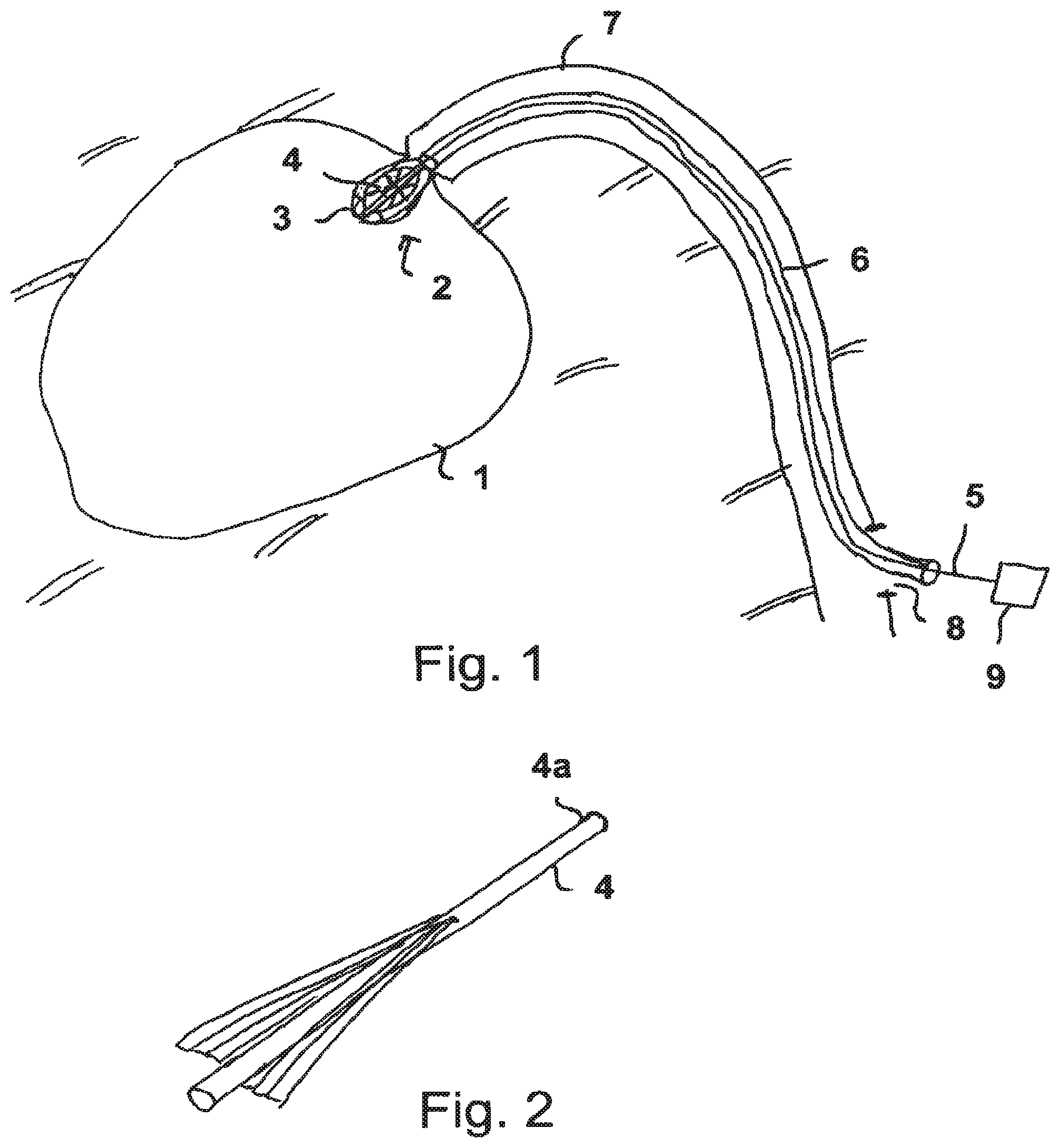
FIG. 1 schematically, a view of a fluid pump on use as a heart catheter pump;
FIG. 2 a rotor in a view in the compressed state;
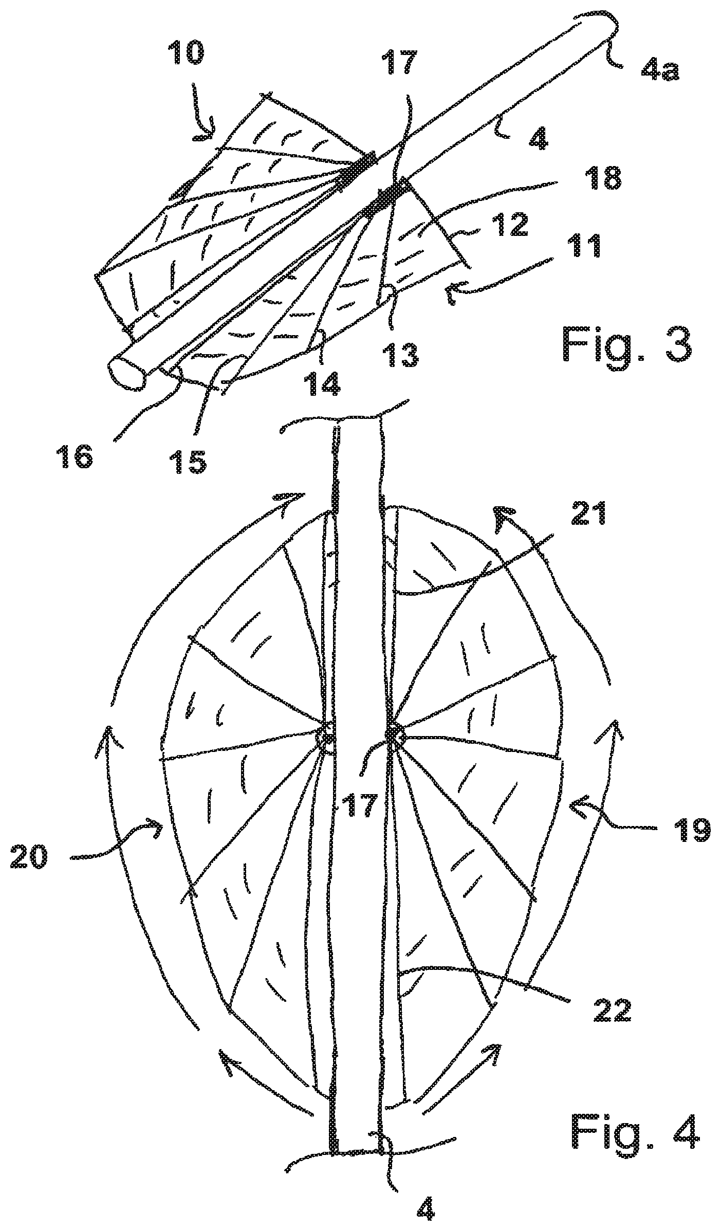
FIG. 3 an embodiment of a rotor in the expanded state;
FIG. 4 a view of a further embodiment of a rotor in the expanded state;
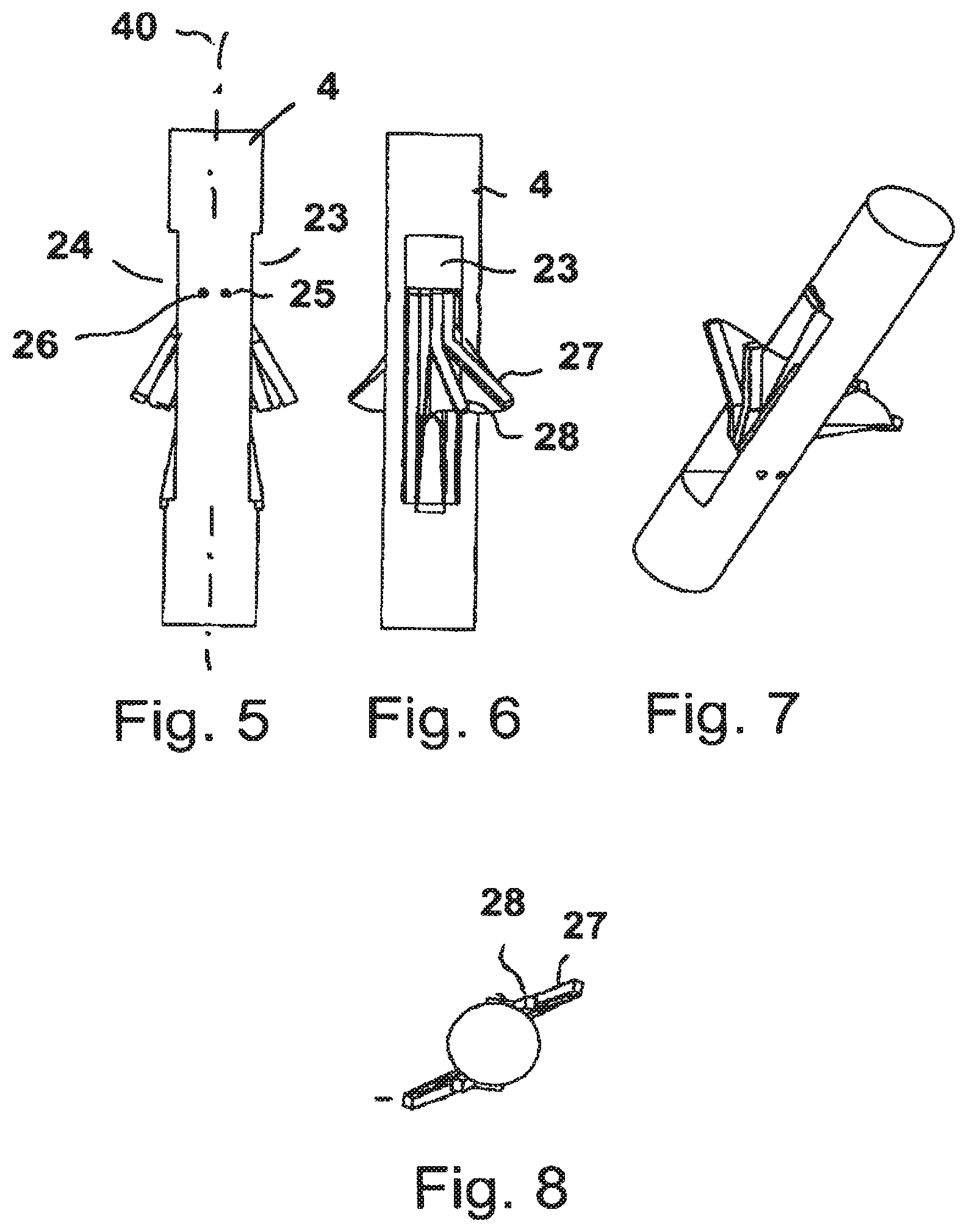
FIG. 5 a side view of a rotor in the compressed state;
FIG. 6 a view of the arrangement of FIG. 5 rotated by 90.degree. about the longitudinal rotor axis;
FIG. 7 a view as in FIGS. 5 and 6, shown three-dimensionally in an oblique view;
FIG. 8 the arrangement of FIGS. 5, 6 and 7 in an axial plan view of the rotor;
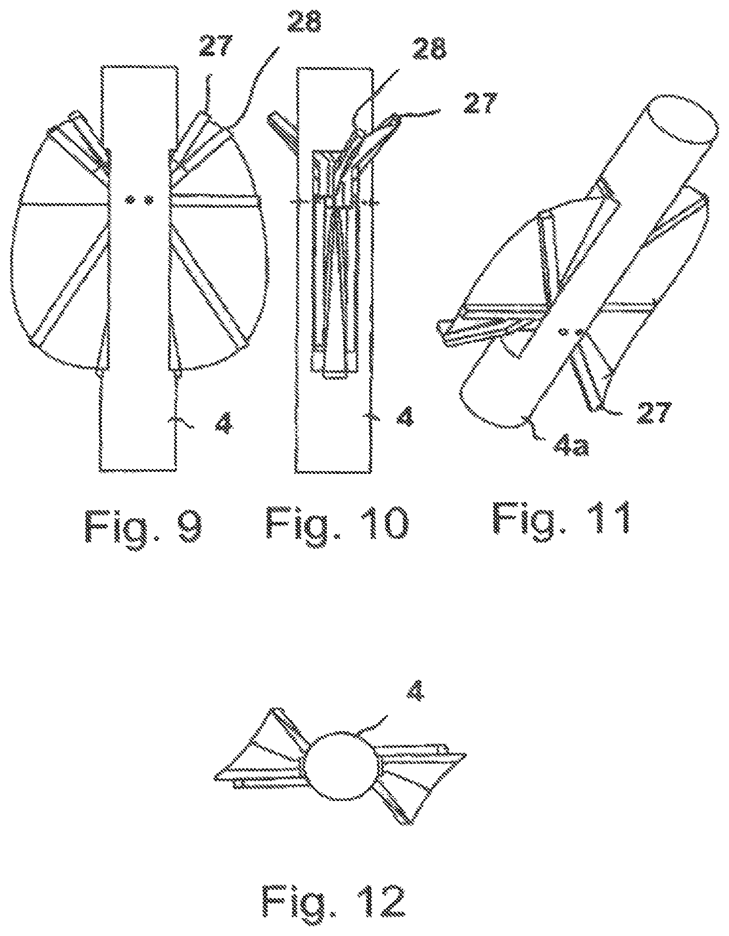
FIG. 9 a side view of the rotor of FIGS. 5 to 8 in the expanded state;
FIG. 10 the view of FIG. 9 rotated by 90.degree. about the longitudinal axis of the rotor;
FIG. 11 an oblique view of the arrangement of FIGS. 9 and 10;
FIG. 12 an axial plan view of the rotor of FIGS. 9 to 11;
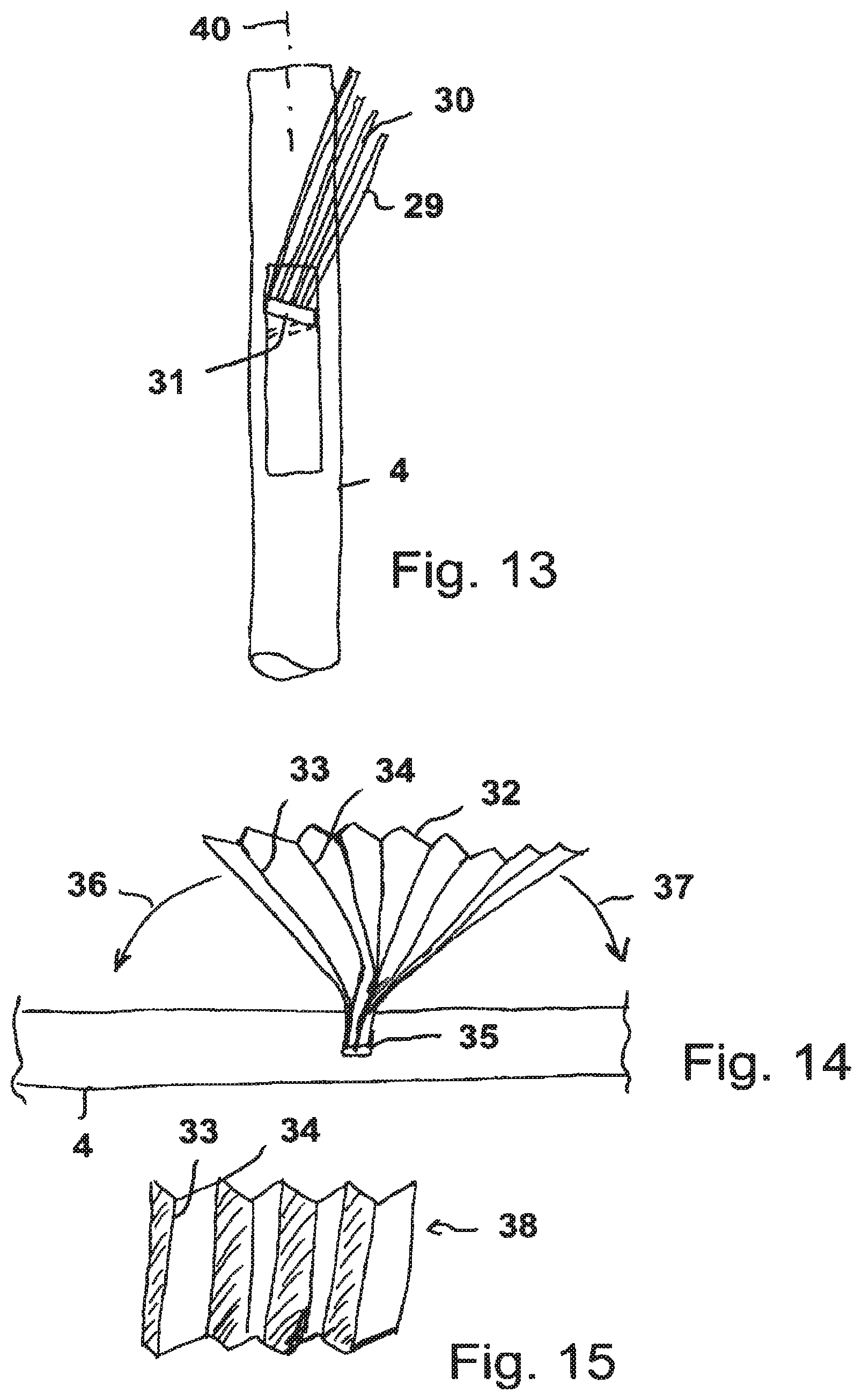
FIG. 13 a side view of a rotor with an inclined pivot plane of the struts;
FIG. 14 a further embodiment with a fan and a fastening to the hub; and
FIG. 15 a three-dimensional view of the conveying element as a folded membrane.
FIG. 1 schematically shows a fluid pump in which the rotor in accordance with the invention is used after the introduction into a ventricle 1. The pump 2 has a housing 3 as well as a hub 4 to which the conveying elements are fastened. The hub 4 is connected to a shaft 5 which is conducted through a hollow catheter 6 within a blood vessel 7 and is conducted out of it and the patient's body by a sluice 8. The rotatable shaft 5 can be driven at high revolutions, for example in the order of 10,000 r.p.m., by means of a motor 9.
Blood can be conveyed between the ventricle 1 and the blood vessel, for example sucked in by the pump 2 and pressed into the blood vessel 7, by means of the rotational movement transmitted onto the hub 4 and onto the conveying elements of the pump.
The pump 2 can have a diameter or general dimensions in the operating state which would be too large to be transported through the blood vessel 7. The pump is radially compressible for this purpose. It is shown in FIG. 1 in the expanded state which it can adopt after the introduction into the ventricle 1 by means of the hollow catheter 6.
The pump is pushed in the compressed state together with the hollow catheter 6 so far through the blood vessel 7 until it projects into the ventricle 1 before it is expanded.
The pump 2 has to be compressed again, which can be done, for example, by corresponding pulling elements, not shown in detail, before the removal, which takes place by pulling out the catheter 6, or, if the pump is only expanded by centrifugal forces, it is stopped and then collapses in on itself.
It is also conceivable to compress the pump at least a little by pulling it into the hollow catheter in that, for example, an introduction funnel is provided at the distal end of the hollow catheter 6.
The design of the hub 4 is shown in more detail in FIG. 2, with the struts of the conveying element/elements being shown in the compressed state, i.e. in the state placed onto the hub. The front end of the hub, which faces the inner space of the ventricle 1, is marked by 4a.
The struts can be placed so tightly on the hub that they only take up a vanishingly small space in the radial direction of the rotor. The membrane is rolled or folded in between the struts in the compressed state.
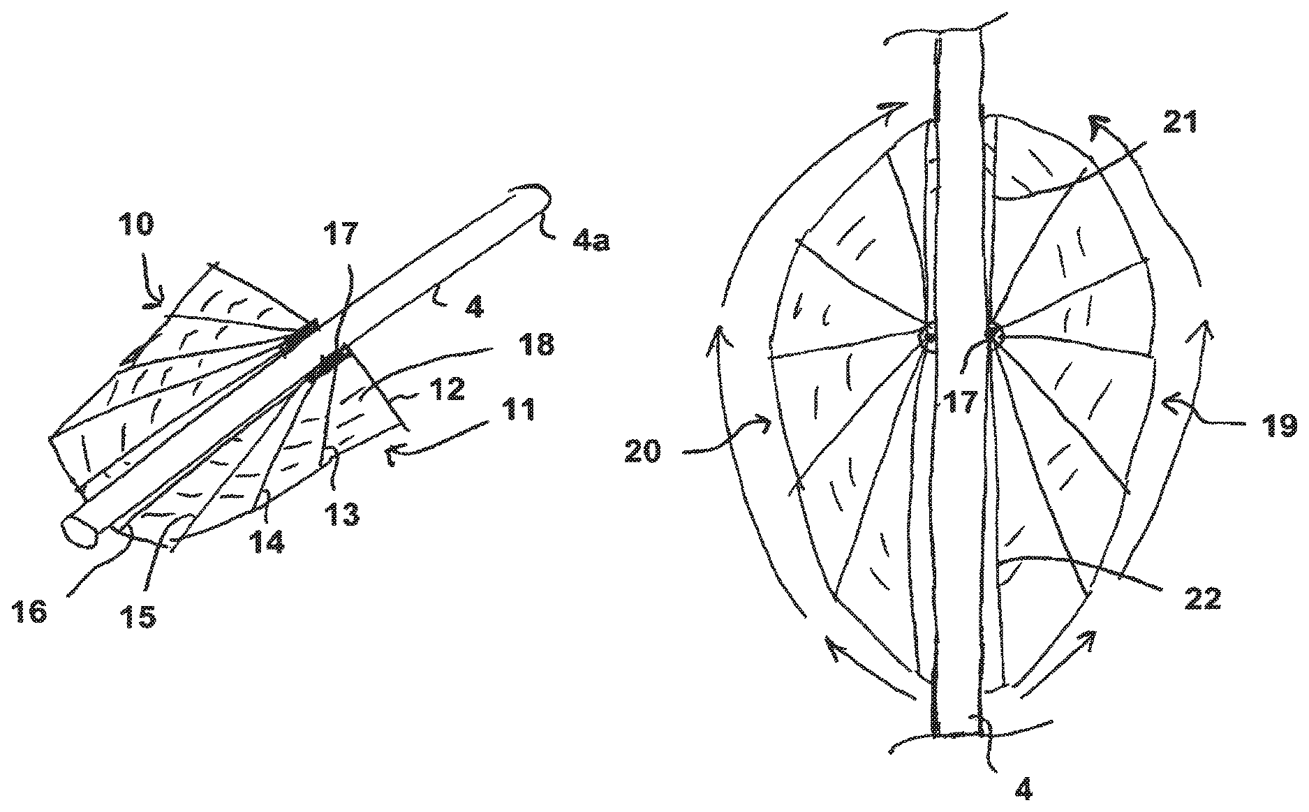
FIG. 3 shows the at least partly expanded state of a rotor with the hub 4, with two conveying elements 10, 11 being provided which are disposed diametrically opposite one another at the periphery of the cylindrically formed hub 4. Each of the conveying elements generally has the shape of a quarter of an ellipse so that the individual struts 12, 13, 14, 15, 16 cover an angular range overall of approximately 90.degree., starting from the base 17. However, other shapes, for example also rectangular shapes, can be achieved by a different design of the length of the struts.
The membrane 18 is tautened flat and tight between the struts 12 to 16 in the expanded state. The conveying element 10 is exactly opposite the conveying elements 11 described in more detail so that both together form half an ellipse in interaction with the hub 4. The struts 16 contacting the hub 4 most closely can, for example, be fixed there by a reception apparatus or can at least be guided. Such a reception apparatus can, for example, be made in U shape with two limbs so that the strut 16 can dip into the conveying elements 11 on their expansion and is held there as required. It is thereby ensured that as good as no intermediate space arises between the strut 16 and the hub 4 which could cause a flowing off of the fluid between the hub and the conveying element and thus a pressure loss if it were present on the rotation of the rotor.
FIG. 4 shows two semi-elliptical conveying elements 19, 20 which are disposed opposite one another at the periphery of the hub 4 which are made with the aid of the struts in the same way as shown in FIG. 3 and which axially contact the hub 4 axially at both sides of the respective base 17 such that a tight connection is present between the hub and the conveying element. Each of the conveying elements covers an angle of 180.degree. in accordance with FIG. 4. Other shapes, for example, rectangular shapes, can also be achieved here by a different design of the length of the struts. The conveying elements of FIG. 4 can also be made in a similar manner from two respective conveying elements in accordance with FIG. 3, with in this case the respective pivot axes not having to be identical.
The struts of an individual conveying element 19, 20 are by all means of different length so that the base 17 does not have to lie axially at the center of the conveying element. As shown in FIG. 4, the strut 21 is, for example, shorter than the oppositely disposed strut 22.
The individual struts can, for example, be manufactured from a plastic in injection molding technology, e.g. can also be contiguous at the base 17, with a membrane being spanned between the struts, either by dipping the struts into a liquid plastic or by one-piece manufacture of the individual conveying elements 19, 20 in the whole from the same material, with the membrane then being provided as a film between the struts.
FIG. 5 shows a side view of a hub 4 having two cut-outs 23, 24 on both sides of the hub which are connected through the hub to form a common opening.
Two shafts 25, 26 on which the struts are pivotably mounted are fastened in this opening. The individual struts are substantially accommodated within the cut-outs 23, 24 in the compressed state, as can be seen much more clearly in the view of FIG. 6 which is rotated by 90.degree. about the axis of rotation 40 with respect to the representation of FIG. 5.
It moreover becomes clear from FIG. 6 that some of the struts 27, 28 are angled a little, at least at their respective ends remote from the pivot axis 25, 26, out of the common pivot plane of the struts which corresponds to the extent of the plane of the drawing in FIG. 5. This design of the struts has the consequence that the struts cannot be completely accommodated in the cut-outs 23, 24, but effects a three-dimensional, optimized design of the conveying element.
A three-dimensional representation of the rotor can be seen in FIG. 7 which clearly shows the ends of the struts which are angled in a projecting manner.
FIG. 8, which shows an axial plan view of the rotor of FIGS. 5 to 7, also clearly shows the projecting ends of the struts 27, 28 and of the struts of the further conveying element disposed opposite them.
FIG. 9 shows in the expanded state of the rotor of FIGS. 5 to 8 how the angled struts 27, 28 effect a curvature of the front edge of the conveying element out of the plane of the membrane, whereby a structure of the conveying element results which is spiral in approach.
This can be seen particularly clearly from FIGS. 10 and 11 respectively. FIG. 12 also clearly shows in plan view that the membrane spanned between the struts is not present in a planar form, but is rather curved.
FIG. 13 makes it clear with reference to another embodiment that the struts 29, 30 can also be slanted with respect to their pivot plane as regards the longitudinal axis/axis of rotation 40 of the hub 4. This is possible, for example, by a corresponding oblique position of the shaft 31 on which the struts 29, 30 are pivotably mounted, as shown in FIG. 13.
A spiral revolution of the conveying element/of the membrane about the hub 4 thus also results on the presence of a planar membrane between the struts 29, 30 so that an axial propulsion of the fluid to be conveyed arises on the rotation of the hub.
The respective other pivot axis which belongs to the oppositely disposed conveying element is then likewise slanted in mirror symmetry to the pivot axis 31.
FIG. 14 shows a design of a conveying element 32 in the form of a folded membrane, with the individual kinks of the membrane which form the struts being marked by 33, 34. In the present example, the kinks are made in parallel. However, they can also be made at an angle to one another or curved.
The membrane can be clamped in a cut-out 35 of the hub 4 in the manner of a fan and can be folded in axially at both sides of the hub, with the membrane stretching. A particularly simple manner of manufacture for the conveying element thus results.
The arrows 36, 37 mark the folding movements of the conveying element to the hub 4 at both sides of the cut-out 35.
FIG. 15 shows the conveying element 38 again in isolated form as a kinked membrane with the kinks/struts 33, 34 before the installation into the cut-out 35 of the hub 4. The cut-out 35 can be introduced into the hub as a slit, for example, with the slit also being able to extend in oblique or curved form with respect to the longitudinal axis 27 to achieve a spiral revolution of the conveying element about the hub.
A particularly inexpensive and simple manner of manufacture of the conveying elements is provided by the design in accordance with the invention of a rotor with corresponding conveying elements which moreover allows a simple compression and expansion of the conveying elements. The space requirements of the rotor on the transport into the operating position are minimized by the invention.
* * * * *
D00000
D00001
D00002
D00003
D00004
D00005
XML
uspto.report is an independent third-party trademark research tool that is not affiliated, endorsed, or sponsored by the United States Patent and Trademark Office (USPTO) or any other governmental organization. The information provided by uspto.report is based on publicly available data at the time of writing and is intended for informational purposes only.
While we strive to provide accurate and up-to-date information, we do not guarantee the accuracy, completeness, reliability, or suitability of the information displayed on this site. The use of this site is at your own risk. Any reliance you place on such information is therefore strictly at your own risk.
All official trademark data, including owner information, should be verified by visiting the official USPTO website at www.uspto.gov. This site is not intended to replace professional legal advice and should not be used as a substitute for consulting with a legal professional who is knowledgeable about trademark law.