Method for producing a component connection and component connection
Hammer , et al. Fe
U.S. patent number 10,550,871 [Application Number 15/434,096] was granted by the patent office on 2020-02-04 for method for producing a component connection and component connection. This patent grant is currently assigned to Bayerische Motoren Werke Aktiengesellschaft. The grantee listed for this patent is Bayerische Motoren Werke Aktiengesellschaft. Invention is credited to Maik Hammer, Jan Andreas Pfrang, Johann Van Niekerk.
| United States Patent | 10,550,871 |
| Hammer , et al. | February 4, 2020 |
Method for producing a component connection and component connection
Abstract
A component connection has a first component, which consists of a metal material, a ball likewise consisting of a metal material, which is welded to the first component, and a second component which has a through-hole and a collar which projects from a top side of the second component, is bent upwards and extends circumferentially around the through-hole. The two components are joined to each other such that the ball projecting from the first component projects into the through-hole provided in the second component or even partially through the through-hole. The second component is arranged so that the collar protrudes from the first component. The second component is a sandwich component which has a middle layer of a plastic material, the middle layer being located between an upper metal layer and a lower metal layer.
| Inventors: | Hammer; Maik (Bruckberg, DE), Van Niekerk; Johann (Munich, DE), Pfrang; Jan Andreas (Munich, DE) | ||||||||||
|---|---|---|---|---|---|---|---|---|---|---|---|
| Applicant: |
|
||||||||||
| Assignee: | Bayerische Motoren Werke
Aktiengesellschaft (Munich, DE) |
||||||||||
| Family ID: | 54106304 | ||||||||||
| Appl. No.: | 15/434,096 | ||||||||||
| Filed: | February 16, 2017 |
Prior Publication Data
| Document Identifier | Publication Date | |
|---|---|---|
| US 20170159694 A1 | Jun 8, 2017 | |
Related U.S. Patent Documents
| Application Number | Filing Date | Patent Number | Issue Date | ||
|---|---|---|---|---|---|
| PCT/EP2015/069117 | Aug 20, 2015 | ||||
Foreign Application Priority Data
| Sep 8, 2014 [DE] | 10 2014 217 895 | |||
| Current U.S. Class: | 1/1 |
| Current CPC Class: | B29C 65/16 (20130101); B29C 65/48 (20130101); F16B 35/06 (20130101); B23K 26/21 (20151001); F16B 5/0664 (20130101); F16B 37/043 (20130101); F16B 5/01 (20130101); F16B 11/006 (20130101); Y10T 403/479 (20150115); Y10T 403/471 (20150115) |
| Current International Class: | B23K 26/21 (20140101); F16B 5/01 (20060101); B29C 65/48 (20060101); B29C 65/16 (20060101); F16B 5/06 (20060101); F16B 35/06 (20060101); F16B 11/00 (20060101) |
| Field of Search: | ;403/266,267,270,271,272,361 |
References Cited [Referenced By]
U.S. Patent Documents
| 4637116 | January 1987 | Paerisch et al. |
| 9296923 | March 2016 | Herzinger |
| 9597755 | March 2017 | Herzinger |
| 2005/0286992 | December 2005 | Shindoh |
| 2006/0231586 | October 2006 | Blanchard et al. |
| 2012/0251226 | October 2012 | Liu |
| 2013/0031756 | February 2013 | Yuen |
| 2013/0269873 | October 2013 | Herzinger et al. |
| 2016/0256958 | September 2016 | Van Niekerk |
| 2016/0303691 | October 2016 | Hammer |
| 1847674 | Oct 2006 | CN | |||
| 34 41 349 | May 1986 | DE | |||
| 10 2010 028 322 | Nov 2011 | DE | |||
| 102010041356 | Mar 2012 | DE | |||
| 10 2010 063 717 | Jun 2012 | DE | |||
| 102010063717 | Jun 2012 | DE | |||
| 10 2012 101 913 | Sep 2013 | DE | |||
| 2006-9996 | Jan 2006 | JP | |||
| WO 2012/084090 | Jun 2012 | WO | |||
Other References
|
Specification Translation of DE 102012101913. Sieg, et al. Lightweight sheet and a lightweight sheet metal comprehensive construction. Sep. 12, 2013. cited by examiner . Chinese-language Office Action issued in counterpart Chinese Application No. 201580037245.4 dated Feb. 7, 2018 with English translation (eight pages). cited by applicant . International Search Report (PCT/ISA/210) issued in PCT Application No. PCT/EP2015/069117 dated Nov. 18, 2015 with English translation (six pages). cited by applicant . German-language Written Opinion (PCT/ISA/237) issued in PCT Application No. PCT/EP2015/069117 dated Nov. 18, 2015 (four pages). cited by applicant . German Office Action issued in counterpart German Application No. 10 2014 217 895.9 dated Jun. 5, 2015 (five pages). cited by applicant . "ThyssenKrupp Steel Europe offers intelligent solutions for the automotive industry: Volkswagen Polo R WRC is easier thanks to LITECOR.RTM.", Trade Press, Mar. 12, 2014, five pages, with unverified translation, https://www.thyssenkrupp-steel-europe.com/de/presse/pressemitteilungen/pr- essemitteilung-2293.html. cited by applicant. |
Primary Examiner: Skroupa; Josh
Attorney, Agent or Firm: Crowell & Moring LLP
Parent Case Text
CROSS REFERENCE TO RELATED APPLICATIONS
This application is a continuation of PCT International Application No. PCT/EP2015/069117, filed Aug. 20, 2015, which claims priority under 35 U.S.C. .sctn. 119 from German Patent Application No. 10 2014 217 895.9, filed Sep. 8, 2014, the entire disclosures of which are herein expressly incorporated by reference.
Claims
What is claimed is:
1. A method for producing a component connection, the method comprising the acts of: providing a first component; welding a ball onto the first component; providing a second component having a through hole and a bent-up collar projecting from a top side of the second component and extending circumferentially around the through hole; joining the first and second components such that the ball projecting from the first component projects into the through hole provided in the second component, the second component being arranged such that the collar projects away from the first component, wherein the second component comprises a sandwich material having a center layer of plastic arranged between a top metal layer and a bottom metal layer, and a region of the center layer of plastic adjacent to the ball gradually decreases in thickness toward the ball.
2. The method according to claim 1, wherein in joining the first and second components the ball projects at least partially through the through hole provided in the second component.
3. The method according to claim 1, wherein the first and second components are mutually joined via an adhesive layer.
4. The method according to claim 1, wherein the act of welding the ball onto the first component is carried out in a contactless manner via a laser welding tool.
5. The method according to claim 1, wherein the through hole of the second component is produced by punching or drilling.
6. The method according to claim 5, wherein after producing the through hole, the bent-up collar is produced by bending up an edge of the through hole.
7. The method according to claim 5, wherein the bent-up collar is produced simultaneously with the punching of the through hole.
8. The method according to claim 1, wherein the bent-up collar of the second component is produced by bending up an edge area of the through hole.
9. A component connection, comprising: a first component of a metal material; a ball of a metal material welded onto the first component; a second component having a through hole and a bent-up collar that projects from a top side of the second component and extends circumferentially around the through hole, wherein the second component is a sandwich component having a center layer of a plastic material situated between a top metal layer and a bottom metal layer, the first and second components are mutually joined such that the ball projecting from the first component extends into the through hole provided in the second component, the second component being arranged such that the bent-up collar projects away from the first component, and a region of the center layer of plastic adjacent to the ball gradually decreases in thickness toward the ball.
10. The component connection according to claim 9, wherein the ball at least partially projects through the through hole of the second component.
11. The component connection according to claim 9, further comprising an adhesive layer gluing the first and second components together.
12. The component connection according to claim 9, wherein the bent-up collar is a clamping collar that rests in a clamping manner from an outside against an outer circumference of the ball.
Description
BACKGROUND AND SUMMARY OF THE INVENTION
The present invention relates to a method for producing a component connection as well as to a component connection so produced.
Such a method and such a component connection, respectively, are known from German patent document DE 10 2010 028 322 A1.
It is an object of the invention to provide a method and a component connection, respectively, which have a broader application spectrum.
This and other objects are achieved according to the invention by a method for producing a component connection with the steps of: providing a first component; welding a ball onto the first component; providing a second component which has a through hole and a bent-up collar projecting from a top side of the second component and extending circumferentially around the through hole; joining the two components such that the ball projecting from the first component projects into the through hole provided in the second component or even projects partially through the through hole, the second component being arranged such that the collar projects away from the first component, wherein a sandwich material is used for the second component, which has a center layer of a plastic material, which center layer is situated between a top metal layer and a bottom metal layer.
The starting point of the invention is a method for producing a component connection, wherein a ball is welded onto a first component. The first component and the ball may consist of a metal material, such as steel, aluminum or the like. However, in principle, the first component and the ball may also consist of a different material, for example, a plastic material, particularly a fiber-reinforced plastic material.
Furthermore, a second component is provided which has a through hole and a bent-up "collar" projecting from a top side of the second component and extending circumferentially around the through hole.
The two components are joined to one another such that the ball, which projects from the first component, projects into the through hole provided in the second component or even partially projects through the through hole. In this case, the second component is arranged such that the collar projects away from the first component.
The core of the invention consists of the fact that, in contrast to the initially mentioned German patent document DE 10 2010 028 322 A1, a "sandwich material" is used for the second component, or that the second component consists of a sandwich material at least in the area around the through hole. The sandwich material according to the invention has a center layer consisting of a plastic material, which center layer is situated between a top metal layer and a bottom metal layer. The two metal layers can be applied directly to surfaces of the center layer that face away from one another. It may, for example, be provided that the center layer consisting of a plastic material has a thickness of 0.6 mm and one metal layer, for example, the top metal layer, has a thickness of 0.25 mm, and the other metal layer, for example, the lower metal layer, has a thickness of 0.2 mm.
Such sandwich components open up multiple application possibilities, for example, in vehicle body construction. By way of the invention, a "sandwich component" (such as a sandwich-type vehicle body component) can very easily be connected with another (vehicle body) component. Sandwich components which, on one side or on both sides, are covered by a metal layer or which have a metal layer on one or both sides are, for example, considered for applications where high EMC compatibility is important, i.e. in the case of applications involving the shielding of electromagnetic radiation.
It may be provided that the ball has a certain excess measurement with respect to the collar. In this case, the collar may be called a "clamping collar", i.e. the collar will then rest in a clamping manner from the outside against an outer circumference of the ball.
According to a further development of the invention, the two components are glued to one another; i.e. an adhesive layer can be inserted between the two components. The adhesive layer may extend directly to the ball and completely fill in conceivable spaces between the collar and the "base of the ball" welded to the first component, whereby it is ensured that no moisture or condensed water can accumulate in this area.
According to a further development of the invention, the ball is welded in a contactless manner by use of a laser welding tool onto the first component. By use of a position detection device, for example, by use of a camera and an electronic analyzing system, the exact position of the ball, for example, the center of the ball can be determined or calculated. The position data provided by the position detection device can be fed to a robot guiding the laser welding tool and controlling the laser welding tool. It may be provided that the ball is connected by way of a circumferential weld seam, i.e. by way of a rotationally symmetrical weld seam, with the first component.
The through hole provided in the second component may be produced, for example, by punching or by drilling. When the through hole is punched out of the second component, the collar can simultaneously be produced by means of punching the through hole. However, this does not necessarily have to be the case. In principle, the collar can also be produced or generated after the production of the through hole by bending up an edge area of the through hole.
Other objects, advantages and novel features of the present invention will become apparent from the following detailed description of one or more preferred embodiments when considered in conjunction with the accompanying drawing.
BRIEF DESCRIPTION OF THE DRAWING
The single FIG. 1 is a schematic view of the fundamental principle of the invention.
DETAILED DESCRIPTION OF THE DRAWING
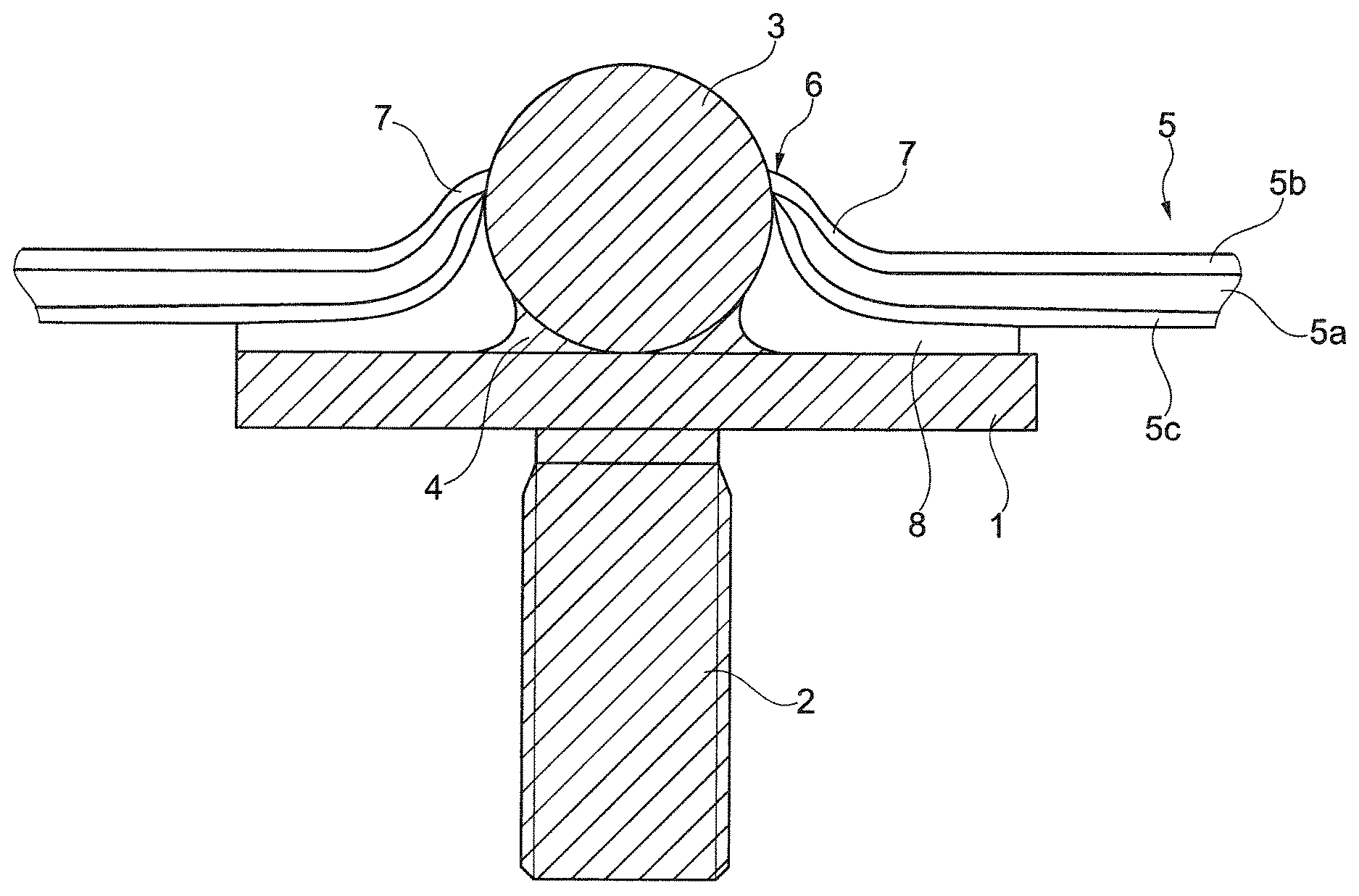
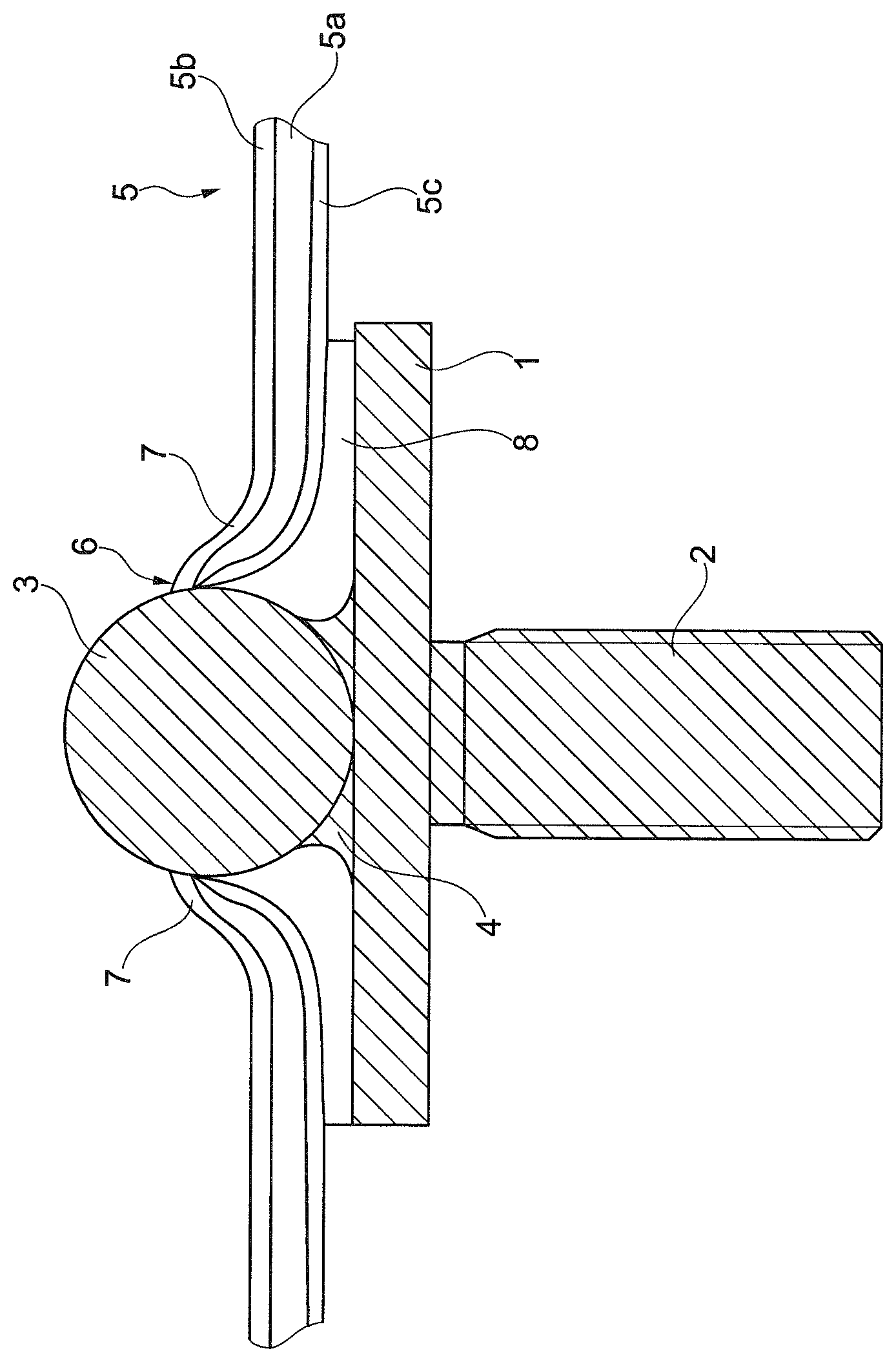
FIG. 1 shows a component connection with a first component 1, which is, for example, a metal sheet or a metal plate (for example, made of steel or aluminum), from which a function element 2 projects 2, which is a threaded bolt in this case. A face of the threaded bolt 2 can welded to the first component 1.
A ball 3 is welded onto a top side of the first component 1 facing away from the function element 2. The ball 3 is firmly bonded by way of a circumferential rotationally symmetrical weld seam 4 with the first component 1. The weld seam 4 can be produced in a robot-controlled, contactless manner by use of a laser welding tool.
A second component 5 is fitted or clipped onto the ball 3 projecting from the first component 1. The second component 5 is a "sandwich component" or a component consisting of a "sandwich-type material". The component 5 has a center layer 5a, which may consist of a plastic material, for example, a fiber-reinforced plastic material. A top layer 5b is applied to a top side of the center layer, which top layer 5b may, for example, be a metal layer. A bottom layer 5c, which may also be a metal layer, is applied to a bottom side of the center layer 5a. The metal layers may, for example, consist of aluminum or contain aluminum.
Before the fitting or clipping of the second component 5 on the ball 3, a through hole is produced, for example, by drilling or by punching. Simultaneously with producing the through hole or subsequently, i.e. after producing the through hole, an edge area of the through hole 6 is bent upward to form a circumferential collar 7. As illustrated in FIG. 1, the second component 5 is arranged such that the collar 7 projects away from the first component 1.
In the embodiment illustrated in FIG. 1, the through hole 6 defined by the collar 7 is slightly larger than the diameter of the ball 3.
As an alternative, it may be provided that the ball 3 has an excess measurement with respect to the through hole 6, so that, when the second component 5 is clipped or fitted onto the ball 3, a clamping connection is established between the ball 3 and the through hole 6 or the inner edge ("collar") of the through hole 6. In this case, the circumferential collar 7 rests clampingly against an outer circumference of the ball 3.
As illustrated in FIG. 1, an adhesive layer 8 is inserted between the first component 1 and the second component 5. The adhesive layer 8 completely fills in the space existing between the collar 7 and the first component 1, whereby it is prevented that moisture or condensed water can accumulate in this area.
The invention is suitable, for example, for a use in vehicle body construction. The second component 5 may, for example, be a vehicle body component, particularly a vehicle body component consisting of plastic and metal. By way of the ball 3 and the clamping collar 7, a function element 2 can be connected with the component 5 in a simple manner.
The foregoing disclosure has been set forth merely to illustrate the invention and is not intended to be limiting. Since modifications of the disclosed embodiments incorporating the spirit and substance of the invention may occur to persons skilled in the art, the invention should be construed to include everything within the scope of the appended claims and equivalents thereof.
* * * * *
References
D00000
D00001
XML
uspto.report is an independent third-party trademark research tool that is not affiliated, endorsed, or sponsored by the United States Patent and Trademark Office (USPTO) or any other governmental organization. The information provided by uspto.report is based on publicly available data at the time of writing and is intended for informational purposes only.
While we strive to provide accurate and up-to-date information, we do not guarantee the accuracy, completeness, reliability, or suitability of the information displayed on this site. The use of this site is at your own risk. Any reliance you place on such information is therefore strictly at your own risk.
All official trademark data, including owner information, should be verified by visiting the official USPTO website at www.uspto.gov. This site is not intended to replace professional legal advice and should not be used as a substitute for consulting with a legal professional who is knowledgeable about trademark law.