Method for producing patient-specific plate
Furrer , et al. Fe
U.S. patent number 10,548,668 [Application Number 15/188,058] was granted by the patent office on 2020-02-04 for method for producing patient-specific plate. This patent grant is currently assigned to DePuy Synthes Products, Inc.. The grantee listed for this patent is DePuy Synthes Products, Inc.. Invention is credited to Andrew Charles Davison, Andre Furrer, Razvan A. Gheorghe, Timo Zillig.


| United States Patent | 10,548,668 |
| Furrer , et al. | February 4, 2020 |
Method for producing patient-specific plate
Abstract
A method of making a patient specific surgical orthopedic implant includes obtaining a virtual model of the orthopedic implant that is configured to fit over a particular tissue body, and virtually designing holes of the orthopedic implant.
| Inventors: | Furrer; Andre (Luterkofen, CH), Zillig; Timo (Mohlin, CH), Davison; Andrew Charles (Dowingtown, PA), Gheorghe; Razvan A. (Oberdorf, CH) | ||||||||||
|---|---|---|---|---|---|---|---|---|---|---|---|
| Applicant: |
|
||||||||||
| Assignee: | DePuy Synthes Products, Inc.
(Raynham, MA) |
||||||||||
| Family ID: | 50234182 | ||||||||||
| Appl. No.: | 15/188,058 | ||||||||||
| Filed: | June 21, 2016 |
Prior Publication Data
| Document Identifier | Publication Date | |
|---|---|---|
| US 20160296290 A1 | Oct 13, 2016 | |
Related U.S. Patent Documents
| Application Number | Filing Date | Patent Number | Issue Date | ||
|---|---|---|---|---|---|
| 13801244 | Mar 13, 2013 | 9411939 | |||
| 61699938 | Sep 12, 2012 | ||||
| Current U.S. Class: | 1/1 |
| Current CPC Class: | A61B 17/8071 (20130101); A61B 34/10 (20160201); G16H 50/50 (20180101); A61B 2017/00526 (20130101); A61B 2034/108 (20160201); A61B 2017/568 (20130101); A61B 2034/102 (20160201) |
| Current International Class: | A61B 34/10 (20160101); G16H 50/50 (20180101); A61B 17/80 (20060101); A61B 17/00 (20060101); A61B 17/56 (20060101) |
References Cited [Referenced By]
U.S. Patent Documents
| 5042983 | August 1991 | Rayhack |
| 5098383 | March 1992 | Hemmy et al. |
| 5147361 | September 1992 | Ojima et al. |
| 5176685 | January 1993 | Rayhack |
| 5413579 | May 1995 | Guilluame |
| 5470335 | November 1995 | Du Toit |
| 5601563 | February 1997 | Burke et al. |
| 5824085 | October 1998 | Sahay |
| 5860981 | January 1999 | Bertin et al. |
| 5876204 | March 1999 | Day et al. |
| 5916220 | June 1999 | Masini |
| 6007537 | December 1999 | Burkinshaw et al. |
| 6077266 | June 2000 | Medoff |
| 6110177 | August 2000 | Ebner et al. |
| 6978188 | December 2005 | Christensen |
| 7621919 | November 2009 | Williams, III et al. |
| 7758345 | July 2010 | Christensen |
| 7824181 | November 2010 | Sers |
| 8086336 | December 2011 | Christensen |
| 8177822 | May 2012 | Medoff |
| 8439926 | May 2013 | Bojarski et al. |
| 8444651 | May 2013 | Kunz et al. |
| 8725465 | May 2014 | Hultgren et al. |
| 8775133 | July 2014 | Schroeder |
| 8992538 | March 2015 | Keefer |
| 9005207 | April 2015 | Dodds et al. |
| 9317631 | April 2016 | Davison et al. |
| 9317634 | April 2016 | Davison et al. |
| 2002/0082604 | June 2002 | Abdelgany et al. |
| 2002/0138078 | September 2002 | Chappuis |
| 2004/0034361 | February 2004 | Dalton |
| 2004/0097946 | May 2004 | Dietzel et al. |
| 2004/0138669 | July 2004 | Horn |
| 2005/0043835 | February 2005 | Christensen |
| 2005/0133955 | June 2005 | Christensen |
| 2008/0195240 | August 2008 | Martin et al. |
| 2008/0221569 | September 2008 | Moore et al. |
| 2008/0275452 | November 2008 | Lang et al. |
| 2009/0047165 | February 2009 | Syvanen et al. |
| 2009/0082774 | March 2009 | Oti et al. |
| 2009/0087276 | April 2009 | Rose |
| 2009/0088758 | April 2009 | Bennett |
| 2009/0092948 | April 2009 | Gantes |
| 2010/0137873 | June 2010 | Grady, Jr. et al. |
| 2010/0152782 | June 2010 | Stone et al. |
| 2010/0168752 | July 2010 | Edwards |
| 2010/0168753 | July 2010 | Edwards et al. |
| 2010/0169057 | July 2010 | Hultgren et al. |
| 2010/0216083 | August 2010 | Grobbee |
| 2010/0262150 | October 2010 | Lian |
| 2010/0292963 | November 2010 | Schroeder |
| 2010/0324558 | December 2010 | Bickley et al. |
| 2011/0008754 | January 2011 | Bassett et al. |
| 2011/0092804 | April 2011 | Schoenefeld et al. |
| 2011/0144698 | June 2011 | Buchbinder et al. |
| 2011/0257653 | October 2011 | Hughes et al. |
| 2012/0022604 | January 2012 | Polley et al. |
| 2012/0029574 | February 2012 | Furrer et al. |
| 2012/0109135 | May 2012 | Bailey |
| 2012/0130686 | May 2012 | Graumann |
| 2012/0141034 | June 2012 | Iannotti et al. |
| 2012/0143267 | June 2012 | Iannotti et al. |
| 2012/0150243 | June 2012 | Crawford et al. |
| 2012/0261848 | October 2012 | Haraszati |
| 2012/0276509 | November 2012 | Iannotti et al. |
| 2012/0289965 | November 2012 | Gelaude et al. |
| 2012/0303131 | November 2012 | Chana |
| 2013/0041630 | February 2013 | Gilles |
| 2013/0072988 | March 2013 | Hulliger |
| 200994836 | Dec 2007 | CN | |||
| 101711695 | May 2010 | CN | |||
| 101742972 | Jun 2010 | CN | |||
| 101790353 | Jul 2010 | CN | |||
| 202184787 | Apr 2012 | CN | |||
| 102429747 | May 2012 | CN | |||
| 0468192 | Sep 1996 | EP | |||
| 1216666 | Jun 2002 | EP | |||
| 1854611 | Nov 2007 | EP | |||
| 1808137 | Apr 2010 | EP | |||
| 2208470 | Jul 2010 | EP | |||
| 2062224 | Aug 2010 | EP | |||
| 2847453 | May 2004 | FR | |||
| 03-075717 | Jul 1991 | JP | |||
| 2002-306517 | Oct 2002 | JP | |||
| WO 2004/039266 | May 2004 | WO | |||
| WO 2005/032790 | Apr 2005 | WO | |||
| 2010/027574 | Mar 2010 | WO | |||
| WO 2011/070367 | Jun 2011 | WO | |||
| WO 2011/071611 | Jun 2011 | WO | |||
| WO 2011/080260 | Jul 2011 | WO | |||
| WO 2011/103689 | Sep 2011 | WO | |||
| 2011/136898 | Nov 2011 | WO | |||
| WO 2012/027574 | Mar 2012 | WO | |||
Other References
|
US. Appl. No. 13/792,746, filed Mar. 11, 2013, Davison et al. cited by applicant . U.S. Appl. No. 13/792,849, filed Mar. 11, 2013, Davison et al. cited by applicant . U.S. Appl. No. 13/801,244, filed Mar. 13, 2013, Furrer et al. cited by applicant . Cevidanes et al., "Three-Dimensional Surgical Simulation", Am. J. Orthod. Dentofacial. Orthop., Sep. 2010, 138(3), 361-371. cited by applicant . Chapuis et al., "A New System for Computer-Aided Preoperative Planning and Intraoperative Navigation During Corrective Jaw Surgery", IEEE Trans. Inf. Technol. Biomed., May 2007, 11(3), 274-287. cited by applicant . DePuy Orthopaedics, Inc., "Tru Match Personalized Solutions", Oct. 27, 2011, 2 pages. cited by applicant . International Patent Application No. PCT/US2013/030131: International Search Report dated Jun. 25, 2013, 11 pages. cited by applicant . International Patent Application No. PCT/US2013/030139: Invitation to Pay Additional Fees dated Jun. 10, 2013, 5 pages. cited by applicant . International Patent Application No. PCT/US2013/030139; International Search Report dated Aug. 6, 2013, 6 pages. cited by applicant . International Patent Application No. PCT/US2013/059226; International Search Report dated Dec. 2, 2013, 10 pages. cited by applicant . Klein et al., A Computerized Tomography (CT) Scan Appliance for Optimal Presurgical and Preprosthetic Planning of the Implant Patient, Practical Periodontics & Aesthetic Dentistry, vol. 5, No. 6, 1993, 33-39. cited by applicant . Lubbers et al., "Surgical Navigation in Craniomaxillofacial Surgery: Expensive Toy or Useful Tool? A Classification of Different Indications", J. Oral Maxillofac. Surg., Jan. 2011, 69(1), 300-308. cited by applicant . Mavili et al., "Use of Three-Dimensional Medical Modeling Methods for Precise Planning of Orthognathic Surgery", J. Craniofac. Surg., Jul. 2007, 18(4), 740-747. cited by applicant . Olszewski et al., "Innovative Procedure for Computer-Assisted Genioplasty: Three-Dimensional Cephalometry, Rapid-Prototyping Model and Surgical Splint", Int. J. Oral Maxillofac. Surg., Jul. 2010, 39(7), 721-724. cited by applicant. |
Primary Examiner: Dorais; Craig C
Attorney, Agent or Firm: BakerHostetler
Parent Case Text
CROSS-REFERENCE TO RELATED APPLICATIONS
This application is a continuation of U.S. patent application Ser. No. 13/801,244 filed Mar. 13, 2013 which claims the benefit of Provisional Application No. 61/699,938 filed Sep. 12, 2012, the disclosure of which is hereby incorporated by reference as if set forth in its entirety herein.
Claims
What is claimed is:
1. A method of preparing an orthopedic implant, the method comprising: identifying a predetermined section of a virtual three-dimensional model of a tissue body, the predetermined section indicating a location, within the tissue body, of nerves, teeth, other specific tissue portions, or hardware; overlaying, via a software program executed by a computing device, a virtual three-dimensional model of an implant body over the virtual three-dimensional model of the tissue body so as to define a manipulated virtual three-dimensional model of the implant body; designing, via the software program, a virtual three-dimensional hole within the virtual three-dimension model of the implant body such that a virtual three-dimensional model of a fastener that is fully seated within the virtual three-dimensional hole does not extend into the predetermined section; generating manufacturing instructions for transmission to a manufacturing machine that is configured to construct a patient specific orthopedic implant that corresponds to the manipulated virtual three-dimensional model of the implant body; and transmitting the manufacturing instructions to the manufacturing machine.
2. The method of claim 1, wherein designing the virtual three-dimensional hole further comprises orienting an axis of the virtual three-dimensional hole at an acute angle relative to an axis that is orthogonal to at least one of an inner surface and an outer surface of the virtual three-dimensional model of the implant body.
3. The method of claim 2, wherein the acute angle is between about zero degrees and about 15 degrees.
4. The method of claim 2, wherein the acute angle is greater than 15 degrees.
5. The method of claim 1, further comprising: designing a second virtual three-dimensional hole within the virtual three-dimensional model of the implant body; and orienting the second virtual three-dimensional hole such that a second virtual three-dimensional model of a fastener that is fully seated within the second virtual three-dimensional hole does not extend into the predetermined section.
6. The method of claim 5, wherein an axis of the virtual three-dimensional hole is angularly offset relative to an axis of the second virtual three-dimensional hole.
7. The method of claim 5, wherein the virtual three-dimensional model of the tissue body defines a first segment and a second segment separated from the first segment, the virtual three-dimensional hole overlies one of the first and second segments, and the second virtual three-dimensional hole overlies the other of the first and second segments.
8. The method of claim 6, wherein the virtual three-dimensional model of the implant body includes a first body portion and a second body portion angularly offset relative to the first body portion, the virtual three-dimensional hole is located in the first body portion, and the second virtual three-dimensional hole is located in the second body portion.
9. The method of claim 1, wherein the virtual three-dimensional model of the implant body includes: a first body portion; a second body portion angularly offset relative to the first body portion; and a third body portion angularly offset relative to each of the first and second body portions.
10. The method of claim 9, wherein: the virtual three-dimensional model of the tissue body includes 1) an anterior surface of a mandible, 2) a lateral surface of the mandible, and 3) at least a portion of a ramus of the mandible; and the overlaying step further comprises 1) overlaying the first body portion over the anterior surface of the mandible, 2) overlaying the second body portion over the lateral surface of the mandible, and 3) overlaying the third body portion over the at least a portion of the ramus of the mandible.
11. The method of claim 10, wherein the virtual three-dimensional hole is a first hole located within the first body portion, and the method further comprises: designing and orienting a second virtual three-dimension hole within the second body portion such that a second virtual three-dimensional model of a fastener that is fully seated within the second virtual three-dimensional hole does not occupy the same virtual three-dimensional space as the predetermined section or the virtual three-dimensional model of the fastener fully seated within the first hole.
12. The method of claim 11, further comprising designing and orienting a third virtual three-dimension hole within the third body portion such that a third virtual three-dimensional model of a fastener that is fully seated within the third virtual three-dimensional hole does not occupy the same virtual three-dimensional space as any of the predetermined section, the virtual three-dimensional model of the fastener fully seated within the first hole, and the second virtual three-dimensional model of the fastener fully seated within the second hole.
13. The method of claim 9, wherein the virtual three-dimensional model of the implant body includes: a fourth body portion angularly offset relative to each of the first, second and third body portions; and a fifth body portion angularly offset relative to each of the first, second, third, and fourth body portions.
14. The method of claim 13, wherein the fourth body portion opposes the second body portion and the fifth body portion opposes the third body portion.
15. The method of claim 1, wherein: the virtual three-dimensional model of the tissue body defines a first segment and a second segment separated from the first segment; and the overlaying step further comprises overlaying the virtual three-dimensional model of the implant body over the first and second segments.
16. The method of claim 15, further comprising identifying an indication of a tissue defect within a third segment of the virtual three-dimensional model of the tissue body located between the first and second segments.
17. The method of claim 16, further comprising: designing, via the software program, a second virtual three-dimensional hole within the virtual three-dimension model of the implant body; and orienting an axis of the second virtual three-dimensional hole such that a second virtual three-dimensional model of a fastener that is fully seated within the second virtual three-dimensional hole 1) extends within the third segment, and 2) does not occupy the same virtual three-dimensional space as the predetermined section or the virtual three-dimensional model of the fastener fully seated within the virtual three-dimensional hole.
18. A method of preparing an orthopedic implant, the method comprising: identifying, in a virtual three-dimensional model of a tissue body, a predetermined section that indicates a location within the tissue body of nerves, teeth, other specific tissue portions, or hardware; designing, via a software program executed by a computing device, a virtual three-dimensional model of an implant body that is contoured to fit over the virtual three-dimensional model of the tissue body; overlaying, via the software program, the virtual three-dimensional model of the implant body over the virtual three-dimensional model of the tissue body so as to define a manipulated virtual three-dimensional model of the implant body; designing, via the software program, a virtual three-dimensional hole within the virtual three-dimension model of the implant body such that a virtual three-dimensional model of a fastener fully seated within the virtual three-dimensional hole does not extend into the predetermined section; and transferring the manipulated virtual three-dimensional model of the implant body to a manufacturing machine, wherein the manufacturing machine is configured to construct a patient specific implant body that corresponds to the manipulated virtual three-dimensional model of the implant body.
19. A method of preparing an orthopedic implant for fixating a first portion and a second portion of a tissue body relative to one another, the method comprising: obtaining a virtual three-dimensional model of the tissue body that includes separated first and second portions; identifying, in the virtual three-dimensional model of the tissue body, a predetermined section of the tissue body, the predetermined section indicating a location within the tissue body of nerves, teeth, other specific tissue portions, or hardware; overlaying, via a software program executed by a computing device, a contoured surface of a virtual three-dimensional model of an implant body over the separated first and second portions of the virtual three-dimensional model of the tissue body so as to define a manipulated virtual three-dimensional model of the implant body, wherein the virtual three-dimensional model of the implant body includes first and second virtual three-dimensional holes each contiguous with the contoured surface, wherein 1) the first virtual three-dimensional hole overlays the first portion of the virtual three-dimensional model of the tissue body, and 2) the second virtual three-dimensional hole overlays the second portion of the virtual three-dimensional model of the tissue body; modifying, via the software program, at least one of the first and second virtual three-dimensional holes such that a virtual three-dimensional model of a fastener fully seated within the at least one of the virtual three-dimensional holes does not extend into the predetermined section; and transferring the manipulated virtual three-dimensional model of the implant body to a manufacturing machine, wherein the manufacturing machine is configured to construct a patient specific implant body that corresponds to the manipulated virtual three-dimensional model of the implant body.
Description
TECHNICAL FIELD
The present disclosure generally relates to methods and systems for producing orthopedic implants, and more particularly, to methods and systems for manufacturing patient-specific mandible plates.
BACKGROUND
Many surgical procedures involve the fixation of orthopedic implants, such as mandible plates, to a bone or a bone graft. One or more fasteners, such as bone screws, can be used to fix the orthopedic implant to the bone or bone graft. Some orthopedic implants include implant holes that are configured to receive fasteners. As such, these orthopedic implants can be attached to the bone or bone graft by inserting a fastener through each implant hole and into the bone or bone graft. However, it is important that the fasteners do not contact certain areas of the bone. For instance, in mandibular reconstruction, the fasteners should not contact nerves, teeth, and/or dental implants to avoid damaging the nerves, the teeth, the dental implant or any other hardware. It is also important that the fasteners do not interfere with each other when inserted through the implant holes of the orthopedic implant. Therefore, it is desirable to adjust the angulation of the implant holes such that the fasteners do not interfere with each other and do not contact specific tissue portions such as the nerves and teeth. The location and orientation of the nerves and teeth of each patient may vary. Accordingly, it is desirable to produce orthopedic implants that are specifically designed for a particular patient in order to adjust the angulation of the implant holes.
SUMMARY
The present disclosure relates to methods of making a patient specific orthopedic implant using, among other things, a computing device running a computer-aided software. In an embodiment, the method includes one or more of the following steps: (a) obtaining a virtual three-dimensional model of a tissue body; (b) designing a virtual three-dimensional model of an orthopedic implant that includes an implant body such that the virtual three-dimensional model of the orthopedic implant is contoured to fit over a particular portion of the virtual three-dimensional model of the tissue body; and (c) designing at least one hole that extends through the implant body such that at least one hole is positioned or angled with respect to the implant body so that a virtual three-dimensional model of a fastener does not extend into a predetermined section of the virtual three-dimensional model of the tissue body when the virtual three-dimensional model of the fastener is at least partially disposed in at least one hole.
In another embodiment, the method includes one or more of the following steps: (a) designing a virtual three-dimensional model of an orthopedic implant that is contoured to fit over a predetermined portion of a virtual three-dimensional model of a tissue body, the virtual three-dimensional model of the orthopedic implant including an implant body; and (b) creating at least one virtual hole that extends through the implant body of the virtual three-dimensional model of the orthopedic implant such that at least one virtual hole is positioned or angled relative to the implant body so that a virtual three-dimensional model of a fastener extends into a predetermined section of a virtual three-dimensional model of the tissue body when the virtual three-dimensional model of the fastener is at least partially disposed in at least one hole.
BRIEF DESCRIPTION OF THE DRAWINGS
The foregoing summary, as well as the following detailed description of the preferred embodiments of the application, will be better understood when read in conjunction with the appended drawings. For the purposes of illustrating the surgical instruments and methods of the present application, there is shown in the drawings preferred embodiments. It should be understood, however, that the application is not limited to the specific embodiments and methods disclosed, and reference is made to the claims for that purpose. In the drawings:
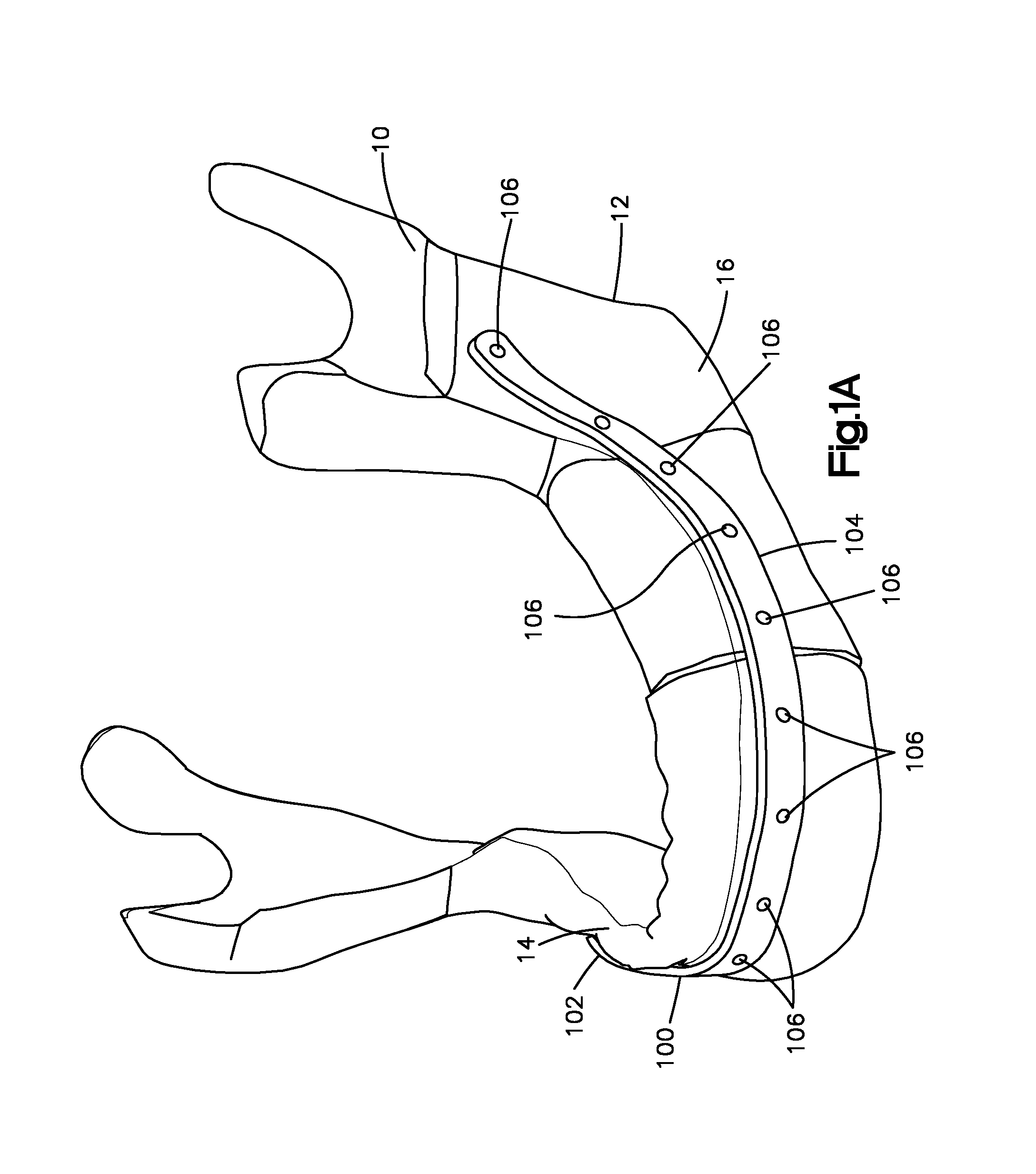
FIG. 1A is a perspective view of a mandible and a patient specific orthopedic implant that is coupled to the mandible, the orthopedic implant defining a plurality of holes, each of the holes configured and sized to receive a fastener;
FIG. 1B is a top transparent view of a portion of the mandible and the orthopedic implant shown in FIG. 1A, showing fasteners inserted through at least some of the holes and into the mandible;
FIG. 1C is a bottom transparent view of the portion of the mandible and the orthopedic implant shown in FIG. 1B;
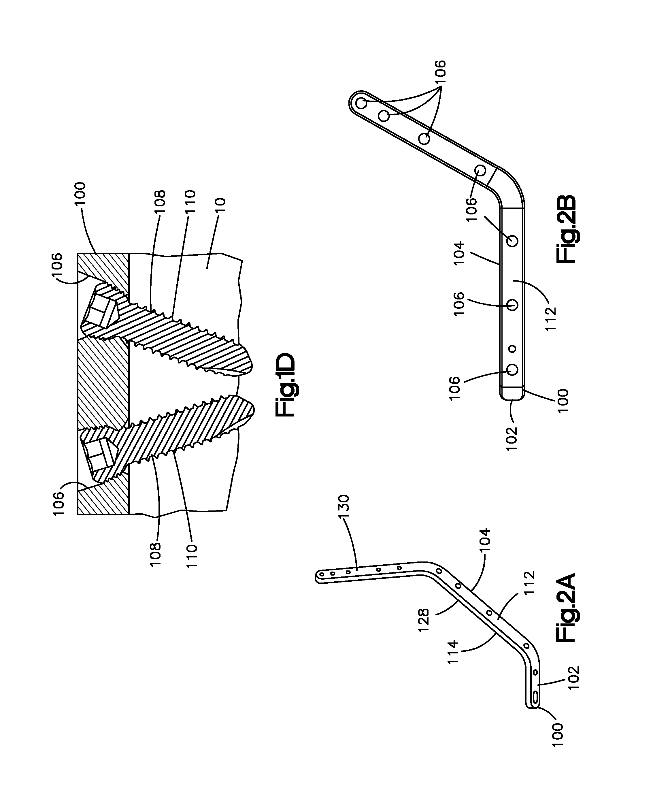
FIG. 1D is an enlarged cross-sectional view of a portion orthopedic implant shown in FIG. 1C, taken around section 1D of FIG. 1C;
FIG. 2A is a perspective view of the patient specific orthopedic implant shown in FIG. 1A;
FIG. 2B is a side view of the patient specific orthopedic implant shown in FIG. 2A;
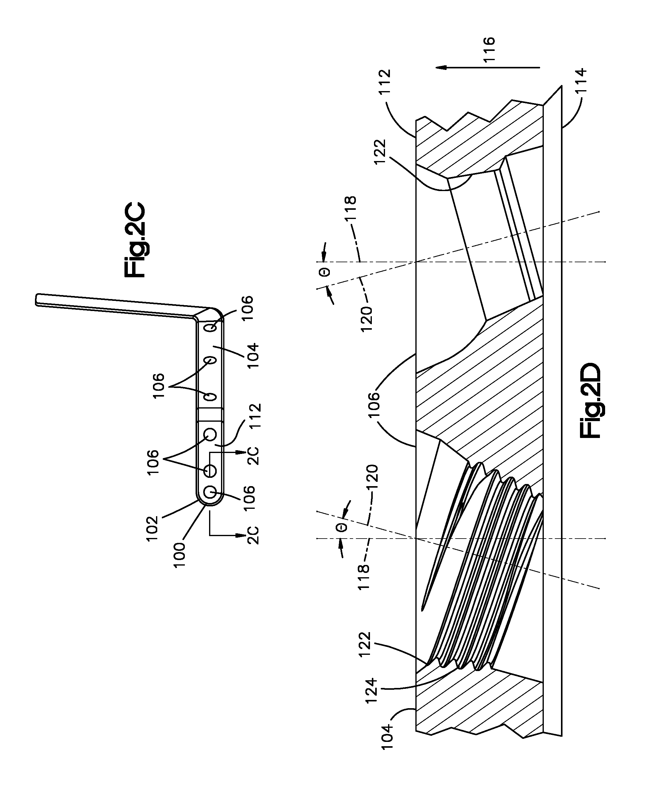
FIG. 2C is a front view of the patient specific orthopedic implant shown in FIG. 2A;
FIG. 2D is an enlarged cross-sectional view of the patient specific orthopedic implant shown in FIG. 2A, taken along section line 2C-2C of FIG. 2C;
FIG. 3A is a perspective view of a patient specific orthopedic implant in accordance with another embodiment of the present disclosure;
FIG. 3B is a perspective view of a patient specific orthopedic implant in accordance with yet another embodiment of the present disclosure; and
FIG. 4 shows a method of making the patient specific orthopedic implants shown in FIGS. 2A-C and 3A-B.
DETAILED DESCRIPTION OF ILLUSTRATIVE EMBODIMENTS
Certain terminology is used in the following description for convenience only and is not limiting. The words "right", "left", "lower" and "upper" designate directions in the drawings to which reference is made. The words "proximally" and "distally" refer to directions toward and away from, respectively, the surgeon using the surgical device. The words, "anterior", "posterior", "superior", "inferior" and related words and/or phrases designate preferred positions and orientations in the human body to which reference is made and are not meant to be limiting. The terminology includes the above-listed words, derivatives thereof, and words of similar import.
With reference to FIGS. 1A-C, a surgical system may include a patient specific orthopedic implant 100 that is configured to be coupled to a tissue body 10 of a patient. The surgical system may further include one or more fasteners 108 that are configured to couple the patient specific orthopedic implant 100 to the tissue body 10. One or more fasteners 108 can be configured as bone screws 110. Regardless of its configuration, each fastener 108 is configured and sized to be inserted in one of the holes 106 and into the tissue body 10 so as to fix the patient specific orthopedic implant 100 to the tissue body 10. The patent specific orthopedic implant 100 can be contoured to fit over a particular portion of the tissue body 10 of a specific patient. As used herein, the tissue body 10 may include a patient's bone such as a mandible 16. Although the drawings show the mandible 16, the tissue body 10 can be other parts of the patient's anatomy such the maxilla.
The patient specific orthopedic implant 100 can be used to fix a first tissue segment 12 of the tissue body 10 to a second tissue segment of the tissue body 10. The first tissue segment 12 may be separated from the second tissue segment by a defect or diseased tissue portion. The defect may be, for example, a fracture. Thus, the first tissue segment 12 can be separated from the second tissue segment 14 by a fracture. The fixation of the first tissue segment 12 and the second tissue segment 14 can promote healing of the tissue body 10. Hence, the patient specific orthopedic implant 100 can support and hold the first tissue segment 12 relative to the second tissue segment 13 while osteogenesis occurs. Alternatively, the patient specific orthopedic implant 100 can be used to fix a bone graft to the first tissue segment 12 and the second tissue segment 14. In such case, a diseased portion of the tissue body 10 may be removed from the patient and replaced with the bone graft. The orthopedic implant 100 can then be used to fix the bone graft to the first tissue segment 12 and the second tissue segment 14. In particular, the bone graft may separate the first tissue segment 12 from the second tissue segment 14. Thus, the patient specific orthopedic implant 100 can support and hold the bone graft relative to the first tissue segment 12 and the second tissue segment 14.
The patient specific orthopedic implant 100 and various of its components are described herein in with reference to orthogonal direction components. That is, various parts of the orthopedic implant 100 can extend along a longitudinal direction L, a lateral direction A, and a transverse direction T. The transverse direction T may be substantially perpendicular to the lateral direction A and the longitudinal direction L. Unless otherwise specified herein, the terms "lateral," "longitudinal," and "transverse" are used to describe the orthogonal directional components of the various parts of the patient specific orthopedic implant 100. When the patient specific orthopedic implant 100 is coupled to the tissue body 10, the transverse direction T extends along the caudal-cranial direction of the patient, the lateral direction A extends along the medial-lateral direction of the patient, and the longitudinal direction L extends along the anterior-posterior direction of the patient.
With reference to FIGS. 2A-C, the patient specific orthopedic implant 100 can be configured as a bone plate 102 and includes an implant body 104 that can be partly or entirely made from any suitable biocompatible material. Suitable biocompatible materials include, but are not limited to, cobalt chromium molybdenum (CoCrMo), titanium, and titanium alloys, stainless steel, ceramics, or polymers such as polyetheretherketone (PEEK), polyetherketoneketone (PEKK), and bioresorbable materials. A coating may be added or applied to the implant body 104 to improve physical or chemical properties or to provide medications. Examples of coatings include plasma-sprayed titanium coating or Hydroxyapatite.
The implant body 104 defines an outer implant surface 112 and an opposed inner implant surface 114. The inner implant surface 114 can be spaced from the outer implant surface 112 along an axial direction 116. Since the implant body 104 may not have a completely planar configuration, the axial direction 116 may be different along different parts of the implant body 104. The thickness of the implant body 104 may be defined from the outer implant surface 112 to the inner implant surface 114 along the axial direction 116. Accordingly, the implant body 104 may define one or more thickness axes 118 that extend between the inner implant surface 114 and the outer implant surface 112. The thickness axis 118 may be substantially perpendicular to the inner implant surface 114 and the outer implant surface 112. The inner implant surface 114 can be contoured to match the contour of a particular outer surface of the tissue body 10 so that the patient specific orthopedic implant 100 can only fit over the that particular outer surface of the tissue body 10.
The patient specific orthopedic implant 100 defines one or more holes 106 that extend through the implant body 104 between the inner implant surface 114 and the outer implant surface 112 (FIG. 2A). Each of the holes 106 can be configured and sized to receive one of the fasteners 108 (FIG. 1B). In operation, one fastener 108 can be inserted through the hole 106 and into the tissue body 10 to couple the patient specific orthopedic implant 100 to the tissue body 10. The holes 106 may be elongate a hole axis 120 that extends between inner implant surface 114 and the outer implant surface 112. The hole axis 120 can be oriented relative to the thickness axis 118 at an angle .theta.. In some embodiments, the angle .theta. may range between about zero (0) to about fifteen (15) degrees. However, the angle .theta. may be more fifteen (15) degrees. The holes 106 may have different hole axes 120 having different angulations. For instance, some holes 106 may define hole axes 120 that are oriented at an oblique angle relative to the thickness axes, whereas other holes 106 may define hole axes 120 that are substantially parallel to the thickness axis 118. The angulation of the holes 106 relative to the thickness axes 118 may depend on a number of factors. For instance, the surgeon may desire to orient a specific hole 106 at a particular angle relative to the thickness axis 118 such that a fastener 108 inserted through that hole 106 does not contact nerves, teeth, or any other desired tissue portion of the tissue body 10. Moreover, the surgeon may desire to orient two or more adjacent holes 106 at specific angles relative to the thickness axis 118 such that, when fasteners 108 are inserted into these holes 108, the fasteners 108 do not interfere with one another (see FIG. 1D).
The implant body 104 may have internal implant surfaces 122 corresponding to each hole 106. Each internal implant surface 122 defines one of the holes 106. Some or all of the holes 106 can be threaded. Therefore, some or all of the holes 106 may include internal implant threads 124 that are configured to mate with external threads of the fastener 108 so that the fastener 108 can be coupled to the implant body 104. Some or all of the holes 106 may not have internal threads.
The patient specific orthopedic implant 100 may be substantially shaped to match the shape of an outer contour of the tissue body 10. In the depicted embodiment, the patient specific orthopedic implant 100 can be designed to be coupled to one side of the mandible 16. To this end, the implant body 104 may include a first implant portion 126 and a second implant portion 128 that is angularly offset from the first implant portion 126 (FIG. 2A). The first implant portion 126 can be configured to fit over an anterior surface of the mandible 16. Moreover, the first implant portion 126 can be connected to the second implant portion 128 at an angular offset. In the depicted embodiment, the first implant portion 126 can be offset relative to the second implant portion 128 at an oblique angle. The second implant portion 128 can be configured to fit over a lateral surface of the mandible 16. The implant body 104 may further include a third implant portion 130 that is angularly offset from the first implant portion 126 and the second implant portion 128. The third implant portion 130 can be connected to the second implant portion 128 at an angular offset. In the depicted embodiment, the third implant portion 130 can be angularly offset relative to the second implant portion 128 at an oblique angle. Moreover, the third implant portion 130 can be configured to fit over at least a portion of the ramus of the mandible 16.
FIG. 3A shows another embodiment of a patient specific orthopedic implant 200 that is similar to the patient specific orthopedic implant 100 described above. The patient specific implant 200 can be configured as a bone plate 202 and includes an implant body 204 that is made from a suitable biocompatible material. Suitable biocompatible materials include, but are not limited to, cobalt chromium molybdenum (CoCrMo), titanium, and titanium alloys, stainless steel, ceramics, or polymers such as polyetheretherketone (PEEK), polyetherketoneketone (PEKK), and bioresorbable materials. The patient specific implant 200 may further define a plurality of holes 206 that extend through the implant body 204. The holes 206 can be substantially similar to the holes 106 of the patient specific implant 100 described above. Thus, the holes 206 are configured to receive fasteners 108. The implant body 204 can be designed to fit over most of the mandible 12. To this end, the implant body 204 may include a first implant portion 226 and a second implant portion 228 that is angularly offset from the first implant portion 226. The first implant portion 226 can be configured to fit over at least a portion of the ramus of the mandible 16. Moreover, the first implant portion 226 can be connected to the second implant portion 228 at an oblique angle. The second implant portion 228 can be configured to fit over a lateral surface of the mandible 16. The implant body 204 can further include a third implant portion 230 that is connected to the second implant portion 228. The third implant portion 230 can be configured to fit over an anterior surface of the mandible 16. Further, the third implant portion 230 can be angularly offset from the second implant portion 228. The implant body 204 includes a fourth implant portion 232 that is connected to the third implant portion 230. The fourth implant portion 232 can be configured to fit over a lateral surface of the mandible 16. Moreover, the fourth implant portion 232 can be angularly offset from the third implant portion 230. The implant body 204 includes a fifth implant portion 234 that is connected to the fourth implant portion 232. The fifth implant portion 234 can be configured to fit over at least a portion of the ramus of the mandible 16. Further, the fifth implant portion 234 can be angularly offset from the fourth implant portion 232. In the orthopedic arts, the patient specific orthopedic implant 200 is referred to as the double-angled implant.
FIG. 3B illustrates another embodiment of a patient specific implant 300. The patient specific implant 300 can be configured to fit over an anterior portion and parts of the two lateral portions of the mandible 16. In the depicted embodiment, the patient specific implant 300 can be configured as a bone plate 302 and includes an implant body 304. The patient specific implant 300 defines holes 306 that extend through the implant body 304. The holes 306 can be configured to receive fasteners 108. The holes 306 can be substantially similar to the holes 106 described above. The implant body 304 includes a first implant portion 326 and a second implant portion 328 that is connected to the first implant portion 326. The first implant portion 326 is configured to fit over a lateral portion of the mandible 16 and is angular offset relative to the first implant portion 326. The second implant portion 328 can fit over an anterior surface of the mandible 16. The implant body 304 can further include a third implant portion 330 that is connected to the second implant portion 328. The second implant portion 328 can be angularly offset relative to the second implant portion 328 and can be configured to fit over a lateral portion of the mandible 16.
FIG. 4 illustrates a method of making any of the patient specific orthopedic implants described above. In the interest of brevity, this method is described in relation to the patient specific orthopedic implant 100. However, the method can be used to make any of the patient specific orthopedic implants described above. This method may include some or all of the steps described below. The patient specific orthopedic implant 100 can be manufactured pre-operatively. Before commencing the appropriate surgery, a virtual three-dimensional image of the tissue body 10 using any suitable technology is obtained. The virtual three-dimensional image of the tissue body 10 can be obtained by scanning the tissue body 10 using a scanning machine 400 that is suitable to scan anatomical tissue. For example, the virtual three-dimensional image of the mandible 16 can be obtained using the scanning machine 400. The scanning machine 400 can be a computed tomography (CT) scan machine, a laser scanning machine, an optical scanning machine, a magnetic resonance imaging (MRI) machine, a coordinate measuring machine or any other machine or device capable of scanning the tissue body 10. Specifically, the scanning machine 400 can be used to scan the tissue body 10. Regardless of the scanning methodology employed, a virtual three-dimensional image of the tissue body 10 is obtained. This image includes images of the tunnels that receive the nerves. Accordingly, the location of the nerves in the tissue body 10 can be identified.
Once the virtual three-dimensional image of the tissue body 10 is obtained, the image data obtained by the scanning machine 400 can then be downloaded or transferred to a computing device 402 to create a virtual three-dimensional model of the tissue body 10. The computing device 402 can be local (i.e., in the same general area as the scanning machine 400) or remote where the image should be transmitted via a network. The computing device 402 includes a processor that is capable of manipulating image data. In addition to the processor, the computing device 402 may include a non-transitory computer-readable storage medium that is capable of storing image data. Alternatively, the computing device 402 may not include a non-transitory computer-readable storage medium; rather, the computing device 402 may be coupled to a non-transitory computer-readable storage medium. In event, the computing device 402 can run a computer-aided design software.
A virtual three-dimensional model of an orthopedic implant, such as the orthopedic implant 100, can be obtained. The virtual three-dimensional model of the orthopedic implant 100 can be composed of data that can be manipulated by a processor and that can be read by a non-transitory computer-readable medium. This data can be in different formats. For example, the virtual three-dimensional model of the orthopedic implant 100 can include data in a Standard Tessellation Language (STL) format. Irrespective of the data format, the virtual three-dimensional model of the orthopedic implant 100 includes data that maps the shape, contour, and size of the orthopedic implant 100. The virtual three-dimensional model of the orthopedic implant 100 can be created virtually in a computer. In the computing device 402 or another computing device, the virtual three-dimensional model of the orthopedic implant 100 is designed so that is contoured and shaped to fit over a particular portion of the virtual three-dimensional model of the tissue body 10. For example, the virtual three-dimensional model of the orthopedic implant 100 can be shaped and contoured to fit over an anterior surface and a lateral surface of the mandible 16. The virtual three-dimensional models of the orthopedic implant 100 and the tissue body 10 can be manipulated using a suitable software such as the software sold under the trademark PROPLAN CMF.RTM. by Synthes.
The virtual three-dimensional model of the orthopedic implant 100 is then processed so as to create one or more holes 106. The user such as a surgeon can determine the angulation and position of the holes 106 in accordance with a predetermined surgical plan. Specifically, the virtual three-dimensional model of the orthopedic implant 100 can be manipulated so that the holes 106 are positioned relative to the implant body 104 such that the fasteners 108 do not extend into a predetermined section of the tissue body 10 when the fasteners are at least partially disposed in the holes 106. For example, the virtual three-dimensional model of the orthopedic implant 100 can be manipulated so that the holes 106 are positioned along the implant body 104 so that the fasteners 108 would not contact nerves or teeth of the tissue body 10. Similarly, the virtual three-dimensional model of the orthopedic implant 100 can be manipulated so that the holes 106 are angled relative to the implant body 104 so that the fasteners 108 would not contact nerves, teeth, and/or dental implants of the tissue body 10. The holes 106 can be positioned or aligned so that the fasteners 108 would not contact any type of hardware such as a dental implant. The user can also manipulate the virtual three-dimensional model of the orthopedic implant 100 to adjust the position and/or angulation of the holes 106 such that the fasteners 108 do not contact one another when the fasteners 108 as illustrated in FIG. 1D. In determining the proper position and/or angulation of the holes 106 with respect to the implant body 104, the user may select the fasteners 108 with the appropriate length so that the fasteners 108 do not interfere with one another when the fasteners 108 are inserted in the holes 106. It is envisioned that the virtual three dimensional models of the fasteners 108 can be obtained. The virtual three-dimensional models of the fasteners 108 can be inserted through the holes 108 of the virtual three-dimensional model of the orthopedic implant 100 to determine whether the fasteners 108 extend into nerves, teeth, or interfere with one another. If the virtual three-dimensional models of the fasteners 108 interfere with nerves, teeth, or each other, the position or angulation of the holes 108 of the virtual three-dimensional model of the orthopedic implant 100 can be manipulated. It is envisioned that the surgeon may manipulate the virtual three-dimensional model of the orthopedic implant 100 before the surgery to reduce the amount of time that is spent in the operating room adjusting the orthopedic implant 100 so that it fits the particular patient. Since the operating room time is reduced, the duration of the anesthesia can be reduced as well.
Once the virtual three-dimensional model of the orthopedic implant 100 has been completed, the orthopedic implant 100 can be created using any suitable technology. The completed virtual three-dimensional model of the orthopedic implant 100 can be downloaded or transferred from the computing device 402 to a manufacturing machine 404 such as a CAD/CAM manufacturing machine. The completed virtual three-dimensional model of the orthopedic implant 100 can be transferred or downloaded directly from the computing device 402 to the manufacturing machine 404 or from the computing device 402 to another computer and then to the manufacturing machine 404. The manufacturing machine 404 can be a computer numerical control (CNC) machine. A suitable software can be used to generate CNC code from the data that represents the virtual three-dimensional model of the orthopedic implant 100. For example, a software sold under the trademark SYNOPSIS.TM. by CADS GmbH can be used to generate the CNC code from the virtual three-dimensional model of the orthopedic implant 100. The software can generate CNC code in any suitable programming language. For instance, the SYNOPSIS or any other suitable software can generate CNC code in G-code or STEP-NC programming languages. The CNC code can then be downloaded or transferred to the CNC machine so that the CNC machine can manufacture the patient specific orthopedic implant 100.
It is envisioned that the methods described above can used not only to manufacture the orthopedic implants described herein but also other orthopedic implants or guiding implant. For instance, the method described herein can be used to manufacture the bone fixation implant and the osteotomy guiding implant that are described in U.S. Patent Application Publication No. 2012/0029574, filed on Apr. 1, 2011, the entire disclosure of which is incorporated herein by reference. Furthermore, the methods described herein can used to manufacture and customize the bone fixation device, bone plate, and aiming guide that are described in U.S. patent application Ser. No. 13/426,079 filed on Mar. 21, 2012, the entire disclosure of which is incorporated by reference.
It should be noted that the illustrations and discussions of the embodiments shown in the figures are for exemplary purposes only, and should not be construed limiting the disclosure. One skilled in the art will appreciate that the present disclosure contemplates various embodiments. For example, although the present disclosure refers to virtual three-dimensional models, it is envisioned that any of the virtual models described in the present disclosure can be two-dimensional. It should be further appreciated that the features and structures described and illustrated in accordance one embodiment can apply to all embodiments as described herein, unless otherwise indicated. Additionally, it should be understood that the concepts described above with the above-described embodiments may be employed alone or in combination with any of the other embodiments described above.
* * * * *
D00000
D00001
D00002
D00003
D00004
D00005
D00006
XML
uspto.report is an independent third-party trademark research tool that is not affiliated, endorsed, or sponsored by the United States Patent and Trademark Office (USPTO) or any other governmental organization. The information provided by uspto.report is based on publicly available data at the time of writing and is intended for informational purposes only.
While we strive to provide accurate and up-to-date information, we do not guarantee the accuracy, completeness, reliability, or suitability of the information displayed on this site. The use of this site is at your own risk. Any reliance you place on such information is therefore strictly at your own risk.
All official trademark data, including owner information, should be verified by visiting the official USPTO website at www.uspto.gov. This site is not intended to replace professional legal advice and should not be used as a substitute for consulting with a legal professional who is knowledgeable about trademark law.