Releaseable catheter hub retainer
Akcay , et al. Fe
U.S. patent number 10,548,522 [Application Number 15/012,013] was granted by the patent office on 2020-02-04 for releaseable catheter hub retainer. This patent grant is currently assigned to Smiths Medical ASD, Inc.. The grantee listed for this patent is Smiths Medical ASD, Inc.. Invention is credited to Gursel Akcay, Harsh Chheda, David Goral, James Muskatello, Brian Paliwoda.


View All Diagrams
| United States Patent | 10,548,522 |
| Akcay , et al. | February 4, 2020 |
Releaseable catheter hub retainer
Abstract
A safety catheter insertion assembly including a catheter hub coupling assembly. The safety catheter insertion assembly having a needle hub slideably coupled to a needle housing such that the needle hub is moveable between a first position wherein an insertion needle extends from the needle housing, and a second position wherein the sharp distal tip is housed within the needle housing, the catheter hub coupling assembly coupling the catheter hub to the needle housing in the first position and releasing the catheter hub from the needle housing in the second position.
| Inventors: | Akcay; Gursel (Madison, CT), Muskatello; James (Southington, CT), Chheda; Harsh (Cheshire, CT), Goral; David (Brookfield, CT), Paliwoda; Brian (Thomaston, CT) | ||||||||||
|---|---|---|---|---|---|---|---|---|---|---|---|
| Applicant: |
|
||||||||||
| Assignee: | Smiths Medical ASD, Inc.
(Plymouth, MN) |
||||||||||
| Family ID: | 62907445 | ||||||||||
| Appl. No.: | 15/012,013 | ||||||||||
| Filed: | February 1, 2016 |
Prior Publication Data
| Document Identifier | Publication Date | |
|---|---|---|
| US 20160220791 A1 | Aug 4, 2016 | |
Related U.S. Patent Documents
| Application Number | Filing Date | Patent Number | Issue Date | ||
|---|---|---|---|---|---|
| 62109715 | Jan 30, 2015 | ||||
| 62109722 | Jan 30, 2015 | ||||
| 62109742 | Jan 30, 2015 | ||||
| 62109745 | Jan 30, 2015 | ||||
| 62109750 | Jan 30, 2015 | ||||
| 62109755 | Jan 30, 2015 | ||||
| 62109735 | Jan 30, 2015 | ||||
| 62109673 | Jan 30, 2015 | ||||
| 62109710 | Jan 30, 2015 | ||||
| 62109759 | Jan 30, 2015 | ||||
| 62109766 | Jan 30, 2015 | ||||
| Current U.S. Class: | 1/1 |
| Current CPC Class: | A61B 5/150992 (20130101); A61B 5/150732 (20130101); A61B 5/1535 (20130101); A61M 25/0097 (20130101); A61M 25/0631 (20130101); A61M 21/02 (20130101); A61M 5/422 (20130101); A61B 5/150221 (20130101); A61B 5/150824 (20130101); A61M 5/3202 (20130101); A61B 5/150259 (20130101); A61B 5/150641 (20130101); A61B 5/145 (20130101); A61B 5/15003 (20130101); A61B 5/14539 (20130101); A61M 39/22 (20130101); A61B 5/150389 (20130101); A61M 2205/0205 (20130101); A61M 2021/0016 (20130101); A61B 5/150503 (20130101); A61B 17/1325 (20130101); A61B 5/1477 (20130101); A61B 5/150213 (20130101); A61M 25/0693 (20130101); A61B 2010/0006 (20130101) |
| Current International Class: | A61M 25/06 (20060101); A61B 5/153 (20060101); A61B 5/15 (20060101); A61M 5/32 (20060101); A61M 5/42 (20060101); A61M 21/02 (20060101); A61M 25/00 (20060101); A61M 39/22 (20060101); A61M 21/00 (20060101); A61B 17/132 (20060101) |
References Cited [Referenced By]
U.S. Patent Documents
| 5000740 | March 1991 | Ducharme |
| 5215528 | June 1993 | Purdy |
| 5279590 | January 1994 | Sinko |
| 5599310 | February 1997 | Bogert |
| 5676658 | October 1997 | Erskine |
| 5700250 | December 1997 | Erskine |
| 5713876 | February 1998 | Bogert |
| 5718688 | February 1998 | Wozencroft |
| 5795339 | August 1998 | Erskine |
| 5853339 | December 1998 | Scerbo |
| 5853393 | December 1998 | Bogert |
| 5911705 | June 1999 | Howell |
| 5935109 | August 1999 | Donnan |
| 5951515 | September 1999 | Osterlind |
| 6004294 | December 1999 | Brimhall |
| 6056726 | May 2000 | Isaacson |
| 6077244 | June 2000 | Botich |
| 6117108 | September 2000 | Woehr |
| 6213978 | April 2001 | Voyten |
| 6221047 | April 2001 | Greene |
| 6287278 | September 2001 | Woehr |
| D448844 | October 2001 | Reis |
| 6379332 | April 2002 | Van Landuyt |
| 6379333 | April 2002 | Brimhall |
| 6461362 | October 2002 | Halseth |
| 6585703 | July 2003 | Kassel et al. |
| 6595955 | July 2003 | Ferguson |
| 6616630 | September 2003 | Woehr |
| 6652490 | November 2003 | Howell |
| 6663592 | December 2003 | Rhad |
| 6709419 | March 2004 | Woehr |
| 6749588 | June 2004 | Howell |
| 6796962 | September 2004 | Ferguson |
| 6902546 | June 2005 | Ferguson |
| 6914212 | July 2005 | Adams |
| 6972002 | December 2005 | Thorne |
| 6984213 | January 2006 | Horner |
| 6986760 | January 2006 | Giambattista |
| 7002098 | February 2006 | Adams |
| 7004927 | February 2006 | Ferguson |
| 7008402 | March 2006 | Ferguson |
| 7106269 | September 2006 | Tonn |
| 7125397 | October 2006 | Woehr |
| 7179244 | February 2007 | Smith |
| 7186239 | March 2007 | Woehr |
| 7214211 | May 2007 | Woehr |
| 7226434 | June 2007 | Carlyon |
| 7255685 | August 2007 | Pressly, Sr. |
| 7264613 | September 2007 | Woehr |
| 7291130 | November 2007 | Mcgurk |
| 7314462 | January 2008 | O'Reagan et al. |
| 7341573 | March 2008 | Ferguson |
| 7357784 | April 2008 | Ferguson |
| 7413562 | August 2008 | Ferguson |
| 7458954 | December 2008 | Ferguson |
| 7507222 | March 2009 | Cindrich |
| 7604616 | October 2009 | Thoresen |
| 7608057 | October 2009 | Woehr |
| 7611485 | November 2009 | Ferguson |
| 7611487 | November 2009 | Woehr |
| 7611499 | November 2009 | Woehr |
| 7618395 | November 2009 | Ferguson |
| 7625360 | December 2009 | Woehr |
| D608886 | January 2010 | Rueckert et al. |
| 7654988 | February 2010 | Moulton |
| 7658725 | February 2010 | Bialecki |
| 7713248 | May 2010 | Lopez |
| 7722569 | May 2010 | Soderholm |
| 7731691 | June 2010 | Cote |
| 7736332 | June 2010 | Carlyon |
| 7736342 | June 2010 | Abriles |
| 7798994 | September 2010 | Brimhall |
| 7806849 | October 2010 | Woehr |
| 7828774 | November 2010 | Harding |
| 7935080 | May 2011 | Howell |
| 7972313 | July 2011 | Woehr |
| 7976502 | July 2011 | Baid |
| 7988664 | August 2011 | Fiser |
| 8096973 | January 2012 | Snow |
| 8100858 | January 2012 | Woehr |
| 8162904 | April 2012 | Takano |
| 8211070 | July 2012 | Woehr |
| 8216188 | July 2012 | Millerd |
| 8257322 | September 2012 | Koehler |
| 8292852 | October 2012 | Mulholland |
| 8348893 | January 2013 | Carlyon |
| 8376994 | February 2013 | Woehr |
| 8382718 | February 2013 | Woehr |
| 8382721 | February 2013 | Woehr |
| 8394064 | March 2013 | Baid |
| 8414539 | April 2013 | Kuracina |
| 8444605 | May 2013 | Kuracina |
| 8460249 | June 2013 | Woehr |
| 8474300 | July 2013 | Mckinnon |
| 8486024 | July 2013 | Steube |
| 8496623 | July 2013 | Burkholz |
| 8506528 | August 2013 | Fiser |
| 8529515 | September 2013 | Woehr |
| 8545454 | October 2013 | Kuracina |
| 8568372 | October 2013 | Woehr |
| 8591467 | November 2013 | Walker |
| 8647313 | February 2014 | Woehr |
| 8702658 | April 2014 | Spearman |
| D709188 | July 2014 | Guala |
| 8784387 | July 2014 | Woehr |
| 8814833 | August 2014 | Farrell |
| 8821439 | September 2014 | Kuracina |
| 8827965 | September 2014 | Woehr |
| 8834422 | September 2014 | Walker |
| 8845584 | September 2014 | Ferguson |
| 8864714 | October 2014 | Harding |
| 8915883 | December 2014 | Baid |
| 8926563 | January 2015 | Steube |
| 8936575 | January 2015 | Moulton |
| 8956328 | February 2015 | Antonucci |
| 9089673 | July 2015 | Fiser |
| 9138564 | September 2015 | Morrissey |
| 9180277 | November 2015 | Erskine |
| 9808580 | November 2017 | Elmen |
| 2002/0133122 | September 2002 | Giambattista |
| 2003/0083621 | May 2003 | Shaw et al. |
| 2003/0199827 | October 2003 | Thorne |
| 2004/0225260 | November 2004 | Villa |
| 2005/0273057 | December 2005 | Popov |
| 2007/0191776 | August 2007 | Bialecki |
| 2012/0035552 | February 2012 | Woehr |
| 2012/0226239 | September 2012 | Green |
| 2013/0030391 | January 2013 | Baid |
| 2013/0178825 | July 2013 | Helm, Jr. |
| 2013/0184645 | July 2013 | Baid |
| 2013/0253443 | September 2013 | Woehr |
| 2013/0281972 | October 2013 | Newby |
| 2013/0296805 | November 2013 | Erskine |
| 2013/0317426 | November 2013 | Fiser |
| 2013/0317440 | November 2013 | Woehr |
| 2014/0018738 | January 2014 | Steube |
| 2014/0025009 | January 2014 | Erskine |
| 2014/0039399 | February 2014 | Burkholz |
| 2014/0046272 | February 2014 | Erskine |
| 2014/0058329 | February 2014 | Walker |
| 2014/0135701 | May 2014 | Woehr |
| 2014/0163470 | June 2014 | Baid |
| 2014/0249488 | September 2014 | Woehr |
| 2014/0257202 | September 2014 | Woehr |
| 2014/0336583 | November 2014 | Morrissey |
| 2014/0371715 | December 2014 | Farrell |
| 2015/0005666 | January 2015 | Terasawa |
| 2015/0005718 | January 2015 | Walker |
| 2015/0032065 | January 2015 | Ferguson |
| 2015/0039009 | February 2015 | Tamano |
| 2015/0073304 | March 2015 | Millerd |
| 2015/0080801 | March 2015 | Tanabe |
| 2015/0126932 | May 2015 | Knutsson |
| 2015/0126933 | May 2015 | Antonucci |
| 2015/0174374 | June 2015 | Woehr |
| 2015/0196737 | July 2015 | Baid |
| 2015/0224267 | August 2015 | Farrell |
| 2016/0220161 | August 2016 | Goral et al. |
| 2016/0220762 | August 2016 | Goral et al. |
| 2016/0220805 | August 2016 | Goral et al. |
| 1011764 | Feb 2004 | EP | |||
| 1292355 | May 2007 | EP | |||
| 1448251 | Jul 2014 | EP | |||
| 2508466 | Oct 2014 | GB | |||
| WO 0241932 | May 2003 | WO | |||
| WO 2006070358 | Mar 2007 | WO | |||
| WO 2012014017 | Feb 2012 | WO | |||
| WO 2012014018 | Feb 2012 | WO | |||
| WO 2013187827 | Dec 2013 | WO | |||
| WO 2014097110 | Jun 2014 | WO | |||
| WO 2014162377 | Oct 2014 | WO | |||
| WO 2015023358 | Feb 2015 | WO | |||
| WO 2015056148 | Apr 2015 | WO | |||
Other References
|
Search Report dated Jun. 1, 2016 for PCT Application No. PCT/US2016/015958, 12 pages. cited by applicant . Search Report dated Aug. 7, 2018 for EP Application No. 16744268.0, 7 pages. cited by applicant . Examination Report dated Jun. 22, 2018 for Australian Application No. 2016211195, 2 pages. cited by applicant . Notice of Acceptance dated Jul. 1, 2019 for Australian Application No. 2016211195, 3 pages. cited by applicant. |
Primary Examiner: Mehta; Bhisma
Assistant Examiner: Trinh; Hong-Van N
Attorney, Agent or Firm: Patterson Thuente Pedersen, P.A.
Parent Case Text
RELATED APPLICATIONS
The present application claims the benefit of U.S. Provisional Application Nos. 62/109,673; 62/109,710; 62/109,715; 62/109,722; 62/109,735; 62/109,742; 62/109,745; 62/109,750; 62/109,755; 62/109,759; 62/109,766, all of which were filed Jan. 30, 2015 and are hereby incorporated herein by reference.
Claims
What is claimed is:
1. A catheter insertion device for use with a catheter having a catheter tube and a catheter hub, the catheter insertion device comprising: a needle housing; an insertion needle having a sharp distal tip, a proximal end and a needle transition positioned therebetween; a needle hub operably coupled to the proximal end of the insertion needle and slidably coupled to the needle housing, the needle hub movable relative to the needle housing between a ready for use position and a safe position; wherein in the ready for use position, the catheter insertion device is configured to be operably coupled to the catheter in a manner in which release of the catheter from the catheter insertion device is inhibited by a safety coupling, the safety coupling including a nose configured to be positioned at least partially interior to the catheter hub, and one or more external hub contacts configured to grip an exterior of the catheter hub; and wherein proximal movement of the needle hub relative to the needle housing from the ready for use position to the safe position: (i) causes the needle transition to shift an actuator of the safety coupling proximally, thereby releasing the grip of the one or more external hub contacts from the exterior of the catheter hub, (ii) positions the sharp distal tip of the insertion needle within the nose to inhibit access to the sharp distal tip, and (iii) causes a needle lock of the catheter insertion device to lock the needle hub relative to the needle housing in the safe position, wherein in the safe position, the needle lock is positioned proximally to the needle transition and inhibits distal movement of the insertion needle relative to the needle housing.
2. The catheter insertion device of claim 1, wherein the one or more external hub contacts includes at least two exterior hub contact surfaces.
3. The catheter insertion device of claim 1, wherein the nose cooperates with the one or more external hub contacts to inhibit removal of the catheter from the catheter insertion device before the needle hub is moved proximally from the ready for use position to the safe position.
4. The catheter insertion device of claim 1, wherein the needle lock includes a bottleneck positioned on the needle housing that interacts with a protuberance on the needle hub to lock the needle hub relative to the needle housing in the safe position.
5. The catheter insertion device of claim 1, wherein in the safe position, the needle lock is positioned proximally to the proximal end of the insertion needle.
6. The catheter insertion device of claim 1, wherein in the safe position, at least a portion of the insertion needle is positioned within an elongate body of the needle housing.
7. The catheter insertion device of claim 1, wherein the needle hub includes a flash chamber.
8. The catheter insertion device of claim 1, wherein the insertion needle includes a notch configured to enable blood to pass therethrough into an annular space that lies between an exterior of the insertion needle and an interior of the catheter tube.
9. The catheter insertion device of claim 1, further comprising a collar positioned circumferentially about at least a portion of the nose and the catheter hub in the ready for use position.
10. The catheter insertion device of claim 9, wherein an outer surface of the nose engages at least partially to an interior of the catheter hub.
11. The catheter insertion device of claim 9, wherein the collar comprises at least one of the one or more external hub contacts.
12. The catheter insertion device of claim 9, wherein the collar and the safety coupling are configured to engage opposing surfaces of the catheter hub.
13. The catheter insertion device of claim 1, wherein the actuator and nose are integrally formed as a single component.
14. The catheter insertion device of claim 1, wherein the actuator includes at least one of the one or more external hub contacts.
15. The catheter insertion device of claim 1, wherein the proximal movement of the needle hub relative to the needle housing to the safe position causes the needle transition to shift the nose proximally out of an interior of the catheter hub.
16. The catheter insertion device of claim 1, wherein the one or more external hub contacts move laterally away from the catheter hub to release the catheter hub.
17. The catheter insertion device of claim 1, wherein the one or more external hub contacts rotate about an axis aligned with the insertion needle to release the catheter hub.
18. The catheter insertion device of claim 1, wherein the one or more external hub contacts are biased toward engagement with the catheter hub.
19. A catheter insertion device for use with a catheter having a catheter tube and a catheter hub, the catheter insertion device comprising: a needle housing; a collar defining a hub receiving space shaped and sized to receive a portion of an exterior of the catheter hub; an insertion needle having a sharp distal tip, a proximal end and a needle transition positioned therebetween; a needle hub operably coupled to the proximal end of the insertion needle and slidably coupled to the needle housing, the needle hub movable relative to the needle housing between a ready for use position and a safe position; wherein in the ready for use position, the catheter insertion device is configured to be operably coupled to the catheter in a manner in which release of the catheter from the catheter insertion device is inhibited by a safety coupling, the safety coupling including an actuator defining a nose configured to be positioned at least partially interior to the catheter hub, and further defining one or more external hub contacts configured to grip the exterior of the catheter hub; and wherein proximal movement of the needle hub relative to the needle housing from the ready for use position to the safe position: (i) causes the needle transition to shift the actuator of the safety coupling proximally, thereby releasing the grip of the one or more external hub contacts from the exterior of the catheter hub, (ii) positions the sharp distal tip of the insertion needle within the nose to inhibit access to the sharp distal tip, and (iii) causes a needle lock of the catheter insertion device to lock the needle hub relative to the needle housing in the safe position, wherein in the safe position, the needle lock is positioned proximally to the needle transition and inhibits distal movement of the insertion needle relative to the needle housing.
Description
TECHNICAL FIELD
The present disclosure relates generally to intravenous catheters that are inserted over a needle, and more particularly to a safety catheter insertion device having a releasable coupling between the catheter insertion device and a catheter hub.
BACKGROUND
Intravenous (IV) therapy is a versatile technique used for the administration of medical fluids to and withdrawal of bodily fluids from patients. IV therapy has been used for various purposes such as the maintenance of fluid and electrolyte balance, the transfusion of blood, the administration of nutritional supplements, chemotherapy, and the administration of drugs and medications. Fluids can be administered intravenously by injection through a hypodermic needle, or intermittently or continuously by infusion using a needle or catheter. The most common intravenous access method utilized by clinicians is the peripheral IV catheter.
A peripheral IV catheter is made of soft, flexible plastic or silicone rubber, generally between fourteen to twenty-four gauge in size. In the conventional venipuncture procedure, a catheter is inserted into a vein in the patient's hand, foot, or the inner aspect of the arm or any vein in the body that will accept an IV catheter. Typical peripheral IV catheters are "over-the needle" catheters where the catheter is coaxially placed over an introducer needle. In order to properly place the catheter into a patient's vein, the sharpened tip of the introducer needle, is used to puncture the skin, tissue, and vein wall to provide a path for placement of the catheter.
Placement of a peripheral IV catheter generally includes preparation of the biological site of the patient. Often a tourniquet is applied proximal to the biological site and a variety of techniques can be used to dilate the patient's vein. While wearing disposable gloves, the clinician cleanses the biological site and a vein is retracted or anchored by placing a thumb over the vein about fifty to seventy-five mm distal to the site. The needle and catheter are introduced into the vein by inserting the bevel of the sharpened tip into the vein at about a twenty to thirty degree angle with the bevel facing up in order to pierce one wall of the vein. The catheter thus rides with the needle through the skin, tissue, and vein wall and into the patient's vein.
Various catheter insertion devices have been developed to provide a needle for catheterization. One such example of this type catheter insertion device is marketed by Smiths Medical ASD, Inc. of St. Paul, Minn., under the TELCO trademark, as described in U.S. Pat. Nos. 7,291,130 and 8,257,322 (depicting an IV catheter insertion device marketed by Smiths Medical ASD, Inc. under the INTUITIV Safety IV Catheters trademark), both of which are incorporated by reference herein. In other cases, the catheter insertion device provides a safety needle assembly that functions to house the sharpened tip of the needle to reduce the likelihood of an inadvertent needle stick. Examples of this type of catheter insertion device are described in U.S. Pat. No. 5,000,740 (depicting an IV catheter insertion device marketed by Smiths Medical ASD, Inc. under the PROTECTIV trademark), U.S. Pat. No. 7,736,342 (depicting an IV catheter insertion device marketed by Smiths Medical ASD, Inc. under the VIAVALVE trademark), both of which are incorporated by reference herein.
To finish placement, the needle and catheter are lowered towards the skin to decrease the entry angle, and the catheter is advanced slightly into the vein. The connection between the catheter and needle is then loosened, so that the catheter can be advanced further into the vein as desired, and the needle can be withdrawn from the catheter. Infusion tubing, which can be connected to the catheter, can then be secured to the insertion site by gauze and adhesive tape.
Catheter insertion devices which attempt to lock the catheter to the catheter insertion device during insertion have been created. However, such devices do not consistently enable a smooth release of the catheter from the needle, particularly in a way that reduces or eliminates the risk of an inadvertent needle stick. Accordingly, the applicants have identified a need for a safety catheter insertion assembly that includes a means for smoothly and passively releasing the catheter from the catheter insertion device upon retraction of the needle to a safe position.
SUMMARY OF THE DISCLOSURE
Embodiments of the present disclosure meet the need for a safety catheter insertion assembly that includes a means for smoothly and passively releasing a catheter from a catheter insertion device upon retraction of the needle to a safe position, thereby inhibiting the risk of an inadvertent needle stick, while improving the catheter insertion process.
One embodiment of the present disclosure provides a safety catheter insertion assembly including a catheter tube, catheter hub, needle housing, insertion needle, and needle hub. The catheter tube has a distal end for insertion into a biological site, a proximal end and a wall defining a lumen extending therebetween. The catheter hub is operably coupled to the proximal end of the catheter. The insertion needle has a sharpened distal tip and a proximal end. The needle hub is fixedly coupled to the proximal end of the insertion needle, and slideably coupled to the needle housing such that the needle hub is moveable between a first position, wherein the insertion needle extends from the needle housing and is positioned coaxially within the lumen of the catheter, and a second position, wherein the catheter is separated from the insertion needle and the sharpened distal tip is housed within the needle housing. The needle housing includes a catheter hub coupling means for coupling the catheter hub to the needle housing in the first position and for releasing the catheter hub from the needle housing in the second position, and a needle hub interlock means for interlocking the needle hub to the needle housing in the second position.
In some versions, the catheter hub coupling means grips an exterior surface of the catheter hub. In some versions, the catheter hub includes a luer lock lug structure positioned on the exterior surface of the catheter hub, where the catheter hub coupling means grips the luer lock lug structure. In some versions, the catheter hub includes a wall defining an interior cavity, and a portion of the needle housing is inserted within the interior cavity and configured to provide supporting contact with the catheter hub interior cavity wall when the needle housing is in the first position. In some versions, the catheter hub coupling means releases the catheter hub prior to the interlocking of the needle hub to the needle housing. In some versions, release of the catheter hub by the catheter hub coupling means is affected by sliding the insertion needle and the needle hub relative to the needle housing. In some versions, the needle hub has a "C" shaped cross section conformed to fit around an outer surface of the needle housing in a manner that inhibits the needle hub from readily separating from the needle housing, yet enables the needle hub and needle housing to slide relative to one another between the first position and the second position with minimal resistance. In some versions, the needle housing includes a wall defining a groove, and the needle hub includes a protuberance configured to slidably fit within the groove thereby inhibiting the needle hub from rotating about a longitudinal axis of the needle housing. In some versions, the wall defining the groove, further defines a bottleneck in the groove that is generally narrower in width than the rest of the groove. In some versions, the protuberance of the needle hub has a wedge shape, wherein the apex of the wedge faces towards the bottleneck in the first position and away from the bottleneck in the second position, thereby interlocking the needle hub to the needle housing in the second position. In some versions, in the first position the sharpened distal tip protrudes slightly beyond the distal end of catheter. In some versions, in the second position the sharpened distal tip is interlocked in a safe position to reduce the risk of an inadvertent needle stick. In some versions, the needle hub includes a flash chamber. In some versions, the flashback chamber is constructed of at least one of a transparent and translucent material configured to enable a clinician to see when fluid enters the flash chamber. In some versions, the flashback chamber includes a microporous flashplug configured to enable air to vent as fluid enters the flash chamber.
Another embodiment of the present disclosure provides a safety catheter insertion device for use with a catheter having a catheter tube and a catheter hub. The safety catheter insertion device includes a needle assembly, a needle housing, a nose, an actuator, and one or more exterior hub contacts. The needle housing has a needle lock. The nose is connected to the needle housing and is constructed and arranged for positioning at least partially interior to the catheter hub. The one or more exterior hub contacts are constructed and arranged to contact an exterior of the catheter hub. The needle assembly has a needle hub and a needle. The needle has a needle tip and a needle transition positioned proximal to the needle tip. The actuator is positioned about the needle and constructed and arranged to move proximally when urged by the needle transition as the needle is moved proximally during needle withdrawal. The needle assembly is operably connected to the needle housing and movable between a ready for use position and a safe position. In the ready for use position, the catheter is assembled to the catheter insertion device with the catheter tube carried over the needle. Removal of the catheter from the catheter insertion device is inhibited at least by engagement of the exterior hub contact to the catheter hub. In the safe position, the needle tip is positioned interior to the nose to inhibit access to the needle tip, and the needle lock of the needle housing is engaged to the needle assembly at a position proximal to the needle tip, to inhibit distal movement of the needle tip from the nose. Proximal movement of the needle assembly during needle withdrawal causes the transition to shift the actuator proximally to release the catheter hub from engagement by the one or more exterior hub contacts after the needle lock engages the needle assembly.
In some versions, the needle includes a protuberance and the needle lock includes a pair of engagement tabs that interact with a protrusion to inhibit distal movement of the needle tip from the nose after the needle assembly is in the safe position. In some versions, the needle lock is positioned proximal to the needle transition when the needle assembly is in the safe position. In some versions, the needle lock is positioned proximal to a proximal end of the needle, when the needle assembly is in the safe position. In some versions, the actuator defines a lumen that extends from a distal end of the actuator to a proximal end of the actuator and that includes a needle abutment contacted by the needle transition to shift the actuator proximally to release the catheter hub from engagement by the exterior hub contact after the needle lock engages the needle assembly. In some versions, the nose includes a nose lumen that slidably receives the needle and that, in the safe position, is unblocked between the distal end of the nose and the needle tip when the needle assembly is in the safe position. In some versions, the needle housing includes an elongate body, wherein at least portions of the needle that lie between the needle hub and the transition are positioned interior to the elongate body when the needle assembly is in the safe position.
In some versions, the safety catheter insertion device further includes an engagement arm that includes the one or more external hub contacts. In some versions, the actuator includes one or more actuator arms that retain the external hub contacts in engagement with the catheter hub by engaging a corresponding engagement arm when the needle assembly is in the ready for use position. In some versions, the safety catheter insertion device further includes a collar connected to the needle housing and positioned at least partially about the nose and the catheter hub when the needle assembly is in the ready for use position. In some versions, the exterior hub contact includes a first contact and a second contact, the first contact positioned distally to the second contact. In some versions, the engagement arm includes a pair of engagement arms and the engagement arms include a pair of actuator arms, each of the pair of engagement arms and actuator arms being positioned on opposing sides of the catheter hub when the needle assembly is in the ready for use position. In some versions, a proximal end of the catheter hub includes a radial rib, the engagement arms being positioned distally of the radial rib to inhibit removal of the catheter from the catheter insertion device. In some versions, the nose includes one or more interior hub contacts that cooperate with the one or more external hub contacts to inhibit removal of the catheter prior to the needle assembly being in the safe position. In some versions, the nose and actuator are separate components, the nose remaining stationary with respect to the needle housing as the actuator moves proximally with the needle assembly. In some versions, at least a portion of the actuator is slidable internally to the nose.
In some versions, the safety catheter insertion device further includes a collar connected to the needle housing and positioned at least partially about the nose and the catheter hub when the needle assembly is in the ready for use position.
In some versions, the safety catheter insertion device further includes a retainer that includes a first set of the one or more exterior hub contacts, the retainer being a unitary structure that includes the nose and the actuator. In some versions, the collar includes a second set of the one or more exterior hub contacts. In some versions, the nose of the retainer includes one or more interior hub contacts that cooperate with the first and second set of exterior hub contacts to inhibit removal of the catheter hub prior to the needle assembly being in the safe position. In some versions, shifting the actuator proximally to release the catheter hub includes shifting the retainer proximally to release the catheter hub from cooperative engagement by the interior hub contacts and the first and second set of exterior hub contacts. In some versions, shifting the retainer proximally includes shifting the one or more interior hub contacts and the first set of exterior hub contacts proximally without shifting the first set of exterior hub contacts. In some versions, the collar includes a tab that inhibits the retainer from shifting proximally prior to the actuator being urged by the needle transition as the needle is moved proximally during needle withdrawal.
In some versions, the safety catheter insertion device further includes an engagement structure including opposed portions, the one or more external hub contacts being positioned on the opposed portions. In some versions, the engagement structure has a "C" shaped construction. In some versions, the opposed portions of the engagement structure are biased toward one another to engage the catheter hub in the ready for use position. In some versions, the nose includes one or more interior hub contacts that cooperate with the one or more external hub contacts to inhibit removal of the catheter prior to the needle assembly being in the safe position. In some versions, the nose and the actuator are formed as a common unitary component that is shifted proximally to release the catheter from engagement. In some versions, the actuator includes a ramp that urges the opposed portions of the engagement structure apart from one another as the actuator is shifted proximally. In some versions, the one or more exterior hub contact surfaces are formed in grooves on the opposed portions of the engagement structure. In some versions, a proximal end of the catheter hub includes a radial rib, the grooves being constructed and arranged to contact the rib of the catheter hub.
In some versions, the safety catheter insertion device further includes an engagement structure that includes the one or more exterior hub contacts and that is constructed and arranged to rotate about an axis coincident with the needle as the actuator shifts proximally to release the catheter hub from engagement. In some versions, the actuator and the engagement structure include complimentary helical surfaces, proximal shifting of the actuator causing the engagement structure to rotate through interaction of the complimentary engaging helical surfaces. In some versions, the engagement structure includes engagement arms that provide exterior hub contacts to engage a rib on the catheter hub, the engagement arms and exterior hub contacts rotating as the actuator shifts proximally to release the catheter hub from engagement.
In some versions, the safety catheter insertion device further includes a collar connected to the needle housing and positioned at least partially about the nose and the catheter hub when the needle assembly is in the ready for use position. In some versions, the nose includes one or more interior hub contacts that cooperate with the one or more external hub contacts to inhibit removal of the catheter prior to the needle assembly being in the safe position. In some versions, the nose and the actuator are formed as a common unitary component.
In some versions, the safety catheter insertion device further includes a catheter. In some versions, the catheter includes a blood control valve positioned internally to the catheter hub, the nose contacting the blood control valve when the catheter is assembled to the catheter housing to contain flashback blood. In some versions, the blood control valve is constructed and arranged to be actuated by insertion of a mating connector into the catheter hub. In some versions, the needle includes a notch that permits blood to flow to an annular space between the needle and the catheter tube with the needle assembly in the ready for use position. In some versions, the catheter hub includes wings.
Another embodiment of the present disclosure provides a safety catheter insertion device for use with a catheter having a catheter tube and a catheter hub. The safety catheter insertion device includes a needle assembly, a needle housing, a nose, an actuator, and an engagement structure. The nose is connected to the needle housing and constructed and arranged for positioning at least partially interior to a catheter hub. The engagement structure includes one or more exterior hub contacts and is arranged to contact an exterior of the catheter hub. The needle assembly has a needle hub and a needle. The needle has a needle tip and a needle transition positioned proximal to the needle tip. The actuator is positioned about the needle and constructed and arranged to move proximally when urged by the needle transition as the needle is moved proximally during needle withdrawal. The needle assembly is operably connected to the needle housing and movable between a ready for use position and a safe position. In the ready for use position, the catheter is assembled to the catheter insertion device with the catheter tube carried over the needle. Removal of the catheter from the catheter insertion device is inhibited at least by engagement of the exterior hub contact to the catheter hub. In the safe position, the needle tip is positioned interior to the nose to inhibit access to the needle tip. Proximal movement of the needle assembly during needle withdrawal causes the transition to shift the actuator proximally to rotate the actuator about an axis coincident with the needle to release the catheter hub from engagement by the one or more exterior hub contacts after the needle lock engages the needle assembly.
Another embodiment of the present disclosure provides a safety catheter assembly safety coupling, including a nose and an actuator. The nose includes a tapered extension extending distally that is sized and shaped to be received within a catheter hub. The nose also includes at least one engagement arm extending from the nose that is engageable to an exterior of the catheter hub to secure the catheter hub to the nose, and being shiftable between an engaged position wherein the at least one engagement arm is engaged to the catheter hub and the catheter hub is inhibited from separation, and a disengaged position wherein the at least one engagement arm is separated from the catheter hub and the catheter hub can be removed from the nose. The at least one engagement arm having a distal portion that engages the catheter hub and a proximal portion that engages the actuator, and being operably coupled to the tapered extension by a resilient member. At least a portion of the actuator being located proximal to the nose and being abuttable to an interior of the proximal portion of the at least one engagement arm and the actuator being shiftable between a distal position, wherein the actuator holds the at least one engagement arm in a first, engaged position by inhibiting inward movement of the proximal portion of the at least one engagement arm and a proximal position, wherein the proximal portion of the at least one engagement arm can move inwardly and the distal portion of the at least one engagement arm is released from the catheter hub and the catheter hub can be removed from the nose.
In some versions, the nose further includes a body portion and a mounting plate portion, wherein the mounting plate portion is fixably couplable to a distal end of a needle housing of the safety catheter assembly. In some versions, the at least one engagement arm further includes two hub diametrically opposed retention fingers. In some versions, the actuator defines a needle passage therethrough wherein the needle passes through the needle passage and includes a needle transition that engages a portion of the passage such that when the needle is withdrawn proximally the actuator is engaged and moved proximally with the needle and the actuator is shifted to the proximal position and the at least one engagement arm is disengaged from the catheter hub. In some versions, the actuator further includes an actuator arm including a radial portion and an arm box portion. In some versions, the arm box portion further includes an exterior wall and side walls defining a distal portion receiver into which the distal portion of the at least one engagement arm is receivable. In some versions, the radial portion of the actuator arm is captured by a slot formed in a needle housing of the safety catheter assembly.
Another embodiment of the present disclosure provides a safety catheter assembly having a safety coupling including a collar, an actuator, a nose, a catheter hub, and a needle. The collar is engageable to the catheter hub. The actuator is located within the collar, and is axially shiftable between a distal position and a proximal position. The nose is located within the collar and partially surrounds a portion of the actuator. The nose has an engagement arm that is shiftable between a catheter hub engaged position, wherein the catheter hub is inhibited from removal from the collar, and a catheter hub disengaged position, wherein the catheter hub is removable from the collar. The engagement arm is resiliently biased toward the catheter hub disengaged position. The engagement arm is shifted to the catheter hub engaged position when the actuator is in the distal position, and is resiliently shifted to the catheter hub disengaged position when the actuator is in the proximal position. The catheter hub is engageable at least partially within the collar and at least partially over the nose. The catheter hub is axially removable from the collar when the engagement arm is in the catheter hub disengaged position. The engagement arm includes a finger portion and a thumb portion that together define a hand gap. The hand gap closely conforms to the catheter hub, such that when the catheter hub is engaged in the hand gap the catheter hub is inhibited from removal. The needle has a needle transition that engages the actuator when the needle is being withdrawn proximally and thereby moves the actuator toward the proximal position.
In some versions, the collar further includes a cupola portion and a cylindrical portion. In some versions, the actuator further includes an actuator needle passage and an external portion. In some versions, the actuator needle passage has a wide portion and a narrow portion, the wide portion being located distally from the narrow portion. In some versions, the external portion presents an arch structure having a roof portion having an inwardly facing nose engaging portion structured to urge the engagement arm inwardly. In some versions, the collar further includes nose bushings internally that are dimensioned to receive and support the nose therein. In some versions, the nose further includes a distal nose and a cylindrical body. In some versions, the cylindrical body is integrally coupled to the nose engaging portion. In some versions, the cylindrical body includes a larger portion and a smaller portion, the larger portion and the smaller portion together defining two radial support receiving slots therebetween. In some versions, the cupola portion is sized and structured to closely conform to a roof portion of the actuator, the roof portion having an inwardly facing nose engaging portion configured to urge the engagement arm inwardly when the actuator is in the distal position.
Another embodiment of the present disclosure provides a safety catheter assembly including a retainer and a collar. The retainer is received within the collar, and includes an actuator and a nose, such that the actuator and the nose form a unitary structure. The retainer and the collar are shaped and sized such that a catheter hub is receivable at least partially within the collar and at least partially over the nose of the retainer. The actuator is shiftable between a distal, engaged ready for use position and a proximal, disengaged safe position. The collar receives a proximal end of the catheter hub therein. The nose engages to an interior of the catheter hub in the distal, engaged ready for use position. The catheter hub is releasable from the collar and the retainer when the actuator is in the proximal, disengaged safe position.
In some versions, the safety catheter assembly includes a needle assembly. In some versions, the safety catheter assembly includes a needle housing, wherein the collar is fixedly coupled to the needle housing. In some versions, the needle housing includes the needle lock configured to interlock the needle assembly to the needle housing in the proximal, disengaged safe position. In some versions, when the actuator is in the distal, engaged ready for use position, a longitudinal axis of the needle assembly and a longitudinal axis of the catheter hub are substantially coaxial or parallel. In some versions, when the actuator is in the proximal, disengaged safe position, the catheter hub is disengageable from the retainer and the collar by angular rotation of the longitudinal axis of the catheter hub to a position such that the longitudinal axis of the catheter hub is no longer substantially coaxial or parallel with the longitudinal axis of the needle assembly. In some versions, the nose includes interior hub contacts that engage to the interior of the catheter hub when the actuator is in the distal, engaged ready for use position. In some versions, the nose engages to the interior of the catheter hub in the distal, engaged ready for use position, such that a distal end of the nose is proximate to a distal end of an interior space of the catheter hub, thereby inhibiting separation of the catheter hub from the collar and the retainer. In some versions, the nose extends distally from the actuator and is structured to sheath the needle tip when the needle tip is retracted to the second, safe position. In some versions, when the nose is in the distal, engaged ready for use position, the length of the nose that extends within the interior of the catheter hub is at least twice a diameter of the nose. In some versions, the interior of the catheter hub is resilient to facilitate disengagement of the catheter hub from the nose. In some versions, the retainer includes exterior hub contacts configured as an arcuate partial wall that engages the proximal end of the catheter hub when the actuator is in the distal, engaged ready for use position, thereby inhibiting separation of the catheter hub from the collar and the retainer. In some versions, the arcuate partial wall further defines a hub flange space into which a flange of the catheter hub is receivable. In some versions, the collar and the retainer are configured to engage opposing surfaces of the proximal end of the catheter hub. In some versions, the collar further includes a step feature that engages the proximal end of the catheter hub. In some versions, the safety catheter assembly further includes structure that engages the retainer with the collar in a rotationally fixed manner while enabling axial movement. In some versions, the retainer further includes one or more proximal extensions and the collar further includes a proximal wall portion defining one or more proximal gaps therein. In some versions, the safety catheter assembly further includes a needle that passes through a needle passage defined through the actuator, wherein the needle has a needle transition proximate to a needle tip. In some versions, the needle passage has a wider portion and a narrower portion sized such that the needle transition is free to pass through the wider portion but not through the narrower portion, whereby the needle transition engages the actuator to retract with the needle.
Another embodiment of the present disclosure provides a safety catheter assembly including a catheter and a safety catheter insertion device. The catheter has a catheter hub and a catheter tube. The safety catheter insertion device is selectively connectable to the catheter hub and includes a needle housing, needle assembly, collar, engagement structure, and actuator. The needle housing has a generally cylindrical elongate body. The needle assembly includes a needle and a needle hub, slideably coupled to the needle housing. The collar is located proximate to a distal end of the needle housing. The engagement structure is coupled to the collar, and includes at least one engagement arm that selectively engages the catheter hub. The actuator is received by the collar and the catheter hub, and includes a wedge portion that is shiftable between a first, ready for use position in which the at least one engagement arm engages the catheter hub, and a second, safe position in which the wedge portion forces the engagement structure open such that the at least one engagement arm disengages the catheter hub.
In some versions, the wedge portion is frustoconical. In some versions, the engagement structure is a C-shaped clamp. In some versions, the actuator is shiftable between the first, ready for use position and the second, safe position in response to proximal movement of the needle. In some versions, the catheter hub is receivable at least partially within the engagement structure and partially over the actuator in the first, ready for use position. In some versions, the catheter hub is releasable from the collar, the actuator, and the engagement structure when the engagement structure is in the second, safe position. In some versions, the needle housing includes a needle lock configured to inhibit movement of the needle assembly from the second, safe position. In some versions, the needle lock includes a bottleneck on the needle housing that engages with a triangular protuberance on the needle assembly when in the second, safe position. In some versions, the actuator includes a nose receivable in the catheter hub in the first, ready for use position. In some versions, the engagement structure is biased to the first, ready for use position in which the at least one engagement arm is engaged and shiftable to the second, safe position in which the at least one engagement arm is expanded and disengaged when the wedge portion shifts relative to the engagement structure. In some versions, the engagement structure includes two engagement arms that selectively engage the catheter hub.
Another embodiment of the present disclosure provides a safety catheter assembly including a catheter and a safety catheter insertion device. The catheter includes a catheter hub and a catheter tube. The safety catheter insertion device is selectively connectable to the catheter hub, and includes a needle housing, a needle assembly, a collar, engagement structure, and actuator. The needle housing has a generally cylindrical elongate body. The needle assembly includes a needle and a needle hub, slideably coupled to the needle housing. The collar is coupled to a distal end of the needle housing and is engageable within the catheter hub. The engagement structure is located within the collar, and includes engagement arms, and is axially rotatable relative to the collar between a first, engaged position, wherein the engagement arms are engaged to the catheter hub, and a second, disengaged position wherein the catheter hub is removable from the engagement structure and the collar. The actuator is located at least partially within the engagement structure, and is axially shiftable relative to the engagement structure and engaged to the engagement structure by a plurality of helical features, whereby the engagement structure is rotationally shifted as the actuator is axially shifted.
In some versions, the needle includes a needle transition which engages with the actuator to move the actuator axially along with the needle as the needle is withdrawn, thereby rotating the engagement structure to the second, disengaged position. In some versions, the plurality of helical features includes raised helical ridges on the actuator. In some versions, the actuator includes a nose. In some versions, the catheter hub includes a plurality of lugs and at least one finger radially extending outwardly therefrom. In some versions, the actuator includes a needle passage with a wider portion and narrower portion sized to receive a needle with a needle transition. In some versions, the collar includes a plurality of vertical ribs and a column. In some versions, the engagement structure includes a collar engaging portion and an actuator engaging portion. In some versions, the engagement structure includes snap features including hooks.
Another embodiment of the present disclosure provides a safety catheter assembly including a catheter and a safety catheter insertion device. The catheter includes a catheter hub and a catheter tube. The safety catheter insertion device is selectively connectable to the catheter hub and includes a needle housing, needle assembly, and safety rod. The needle housing has a generally cylindrical elongate body. The needle assembly includes a needle and a needle hub with a tail portion having a safety rod channel defined therein. The needle assembly is slideably coupled to the needle housing between a first, ready for use position, wherein a portion of the needle extends through the catheter hub and exposes a sharpened tip, and a second, safe position, wherein the sharpened tip of the needle is housed by the needle housing to inhibit an inadvertent needle stick. The safety rod has a catheter hub engaging portion and a guide portion, wherein the guide portion traverses the safety rod channel of the needle assembly when the needle assembly is retracted from the first, ready for use position to the second, safe position, including pivotal interaction with the safety rod channel that causes the catheter hub engaging portion to rotate from a first, catheter hub retention position to a second, catheter hub disengagement position.
In some versions, the needle housing includes a needle lock configured to inhibit movement of the needle assembly from the second, safe position. In some versions, the needle lock includes a bottleneck on the needle housing that engages with a triangular protuberance on the needle assembly when in the second, safe position. In some versions, the needle assembly includes a flash chamber with a flash plug. In some versions, the needle housing includes a nose portion for at least partial positioning within the catheter hub. In some versions, the nose portion includes an aperture for the needle to pass through. In some versions, the needle housing includes a protrusion for receiving a portion of the safety rod. In some versions, the safety rod channel includes a "J" hook for pivoting the safety rod relative to the needle housing. In some versions, the catheter hub engaging portion and guide portion are oriented in the same direction.
The summary above is not intended to describe each illustrated embodiment or every implementation of the present disclosure. The figures and the detailed description that follow more particularly exemplify these embodiments.
BRIEF DESCRIPTION OF THE DRAWINGS
The disclosure can be more completely understood in consideration of the following detailed description of various embodiments of the disclosure, in connection with the accompanying drawings, in which:
FIG. 1 is a perspective view depicting a safety catheter assembly according to a first embodiment of the disclosure, wherein the safety catheter assembly includes a catheter and a catheter insertion device and is in a first, ready for use position, wherein the catheter is securely connected to the catheter insertion device by a safety coupling.
FIG. 2a is a perspective view depicting the intravenous catheter assembly of FIG. 1 in a second, safe position, wherein the catheter is released from the catheter insertion device and a sharp tip of an insertion needle of the catheter insertion device is safely housed within the catheter insertion device.
FIG. 2b is a perspective view depicting another version of a safety catheter assembly according to a first embodiment of the disclosure in a first, ready for use position, wherein the catheter hub includes a side port, wings, hollow tubing, a tubing clamp, and a tube connector.
FIG. 3a is a side perspective view depicting a needle assembly of a catheter insertion device, which can be common to all embodiments of the disclosure.
FIG. 3b is a distal end view depicting the needle assembly of FIG. 3a.
FIG. 3c is a bottom perspective view depicting the needle assembly of FIG. 3a.
FIG. 4a is a bottom perspective view depicting an interaction between a needle assembly and a needle housing of a catheter insertion device, which can be common to all embodiments of the disclosure, wherein the needle assembly is positioned relative to the needle housing in a first, ready for use position.
FIG. 4b is a bottom perspective view depicting the interaction between a needle assembly and a needle housing of a catheter insertion device of FIG. 4a, wherein the needle assembly is approaching a second, safe position relative to the needle housing.
FIG. 5a is a top view depicting a safety catheter assembly according to a first embodiment of the disclosure in a first, ready for use position.
FIG. 5b is a cross section view depicting the safety catheter assembly of FIG. 5a.
FIG. 6a is a top view depicting the safety catheter assembly of FIG. 5a in a second, safe position.
FIG. 6b is a cross section view depicting the safety catheter assembly of FIG. 6a.
FIG. 7 is a perspective view depicting a unitary structure including a nose and a pair of catheter contacting engagement arms of a safety coupling according to a first embodiment of the disclosure.
FIG. 8 is a perspective view depicting an actuator of a safety coupling according to a first embodiment of the disclosure.
FIG. 9a is a cross sectional view depicting a catheter, a needle housing and an alternative version of a safety coupling according to a first embodiment of the disclosure in a first, ready for use position, wherein the catheter is securely connected to the needle housing by the safety coupling.
FIG. 9b is a cross sectional view depicting the safety catheter assembly of FIG. 9a in a second, safe position, wherein an actuator of the safety coupling has been shifted proximally, enabling an engagement arm of the safety coupling to pivot laterally away from the catheter, thereby releasing the catheter from the needle housing.
FIG. 10a is a perspective view depicting a safety catheter assembly according to a second embodiment of the disclosure, wherein the safety catheter assembly includes a catheter and a catheter insertion device and is in a first, ready for use position, wherein the catheter is securely connected to the catheter insertion device by a safety coupling including a collar.
FIG. 10b is a perspective view depicting the safety catheter assembly of FIG. 10a with the collar removed to provide a better view of an actuator and an engagement structure of the safety coupling in the first, ready for use position.
FIG. 10c is a perspective view depicting the catheter insertion device and the safety coupling of FIG. 10b, with the actuator and the engagement structure of the safety coupling in a second, safe position, wherein the catheter (not depicted) is released from the catheter insertion device and a sharp tip of an insertion needle of the catheter insertion device is safely housed within the catheter insertion device.
FIG. 11a is a fragmentary cross sectional view depicting a safety catheter assembly according to a second embodiment of the disclosure in a first, ready for use position, wherein a catheter contacting engagement arm of an engagement structure is held in contact with a catheter by an actuator of the safety coupling.
FIG. 11b is fragmentary cross sectional view depicting the safety catheter assembly of FIG. 11b in a second, safe position, wherein the actuator has been shifted proximally, enabling the engagement arm to pivot laterally away from the catheter, and thereby releasing the catheter.
FIG. 12a is a distal perspective view depicting a collar of a safety coupling according to a second embodiment of the disclosure.
FIG. 12b is a proximal perspective view depicting the collar of FIG. 12a.
FIG. 13a is a distal perspective view depicting an actuator of a safety coupling according to a second embodiment of the disclosure.
FIG. 13b is a cross sectional view depicting the collar of FIG. 13a.
FIG. 14a is a distal perspective view depicting an engagement structure of a safety coupling according to a second embodiment of the disclosure.
FIG. 14b is a proximal perspective view depicting the engagement structure of FIG. 14a.
FIG. 15a is a perspective view depicting a safety catheter assembly according to a third embodiment of the disclosure, wherein the safety catheter assembly includes a catheter and a catheter insertion device and is in a first, ready for use position, wherein the catheter is securely connected to the catheter insertion device by a safety coupling.
FIG. 15b is a perspective view depicting the catheter insertion device and safety coupling of FIG. 15a in a second, safe position, wherein the catheter (not depicted) is released from the catheter insertion device and a sharp tip of an insertion needle of the catheter insertion device is safely housed within the catheter insertion device.
FIG. 15c is a distal end view depicting the catheter insertion device and safety coupling of FIG. 15b.
FIG. 16a is a fragmentary cross sectional view depicting a safety catheter assembly according to a third embodiment of the disclosure in a first, ready for use position, wherein safety catheter assembly includes a safety coupling having a retainer and a collar positioned relative to one another so as to engage a catheter of the safety catheter assembly.
FIG. 16b is a fragmentary cross sectional view depicting the safety catheter assembly of FIG. 11a in a second, safe position, wherein the retainer has been shifted proximally thereby releasing the catheter from the safety coupling.
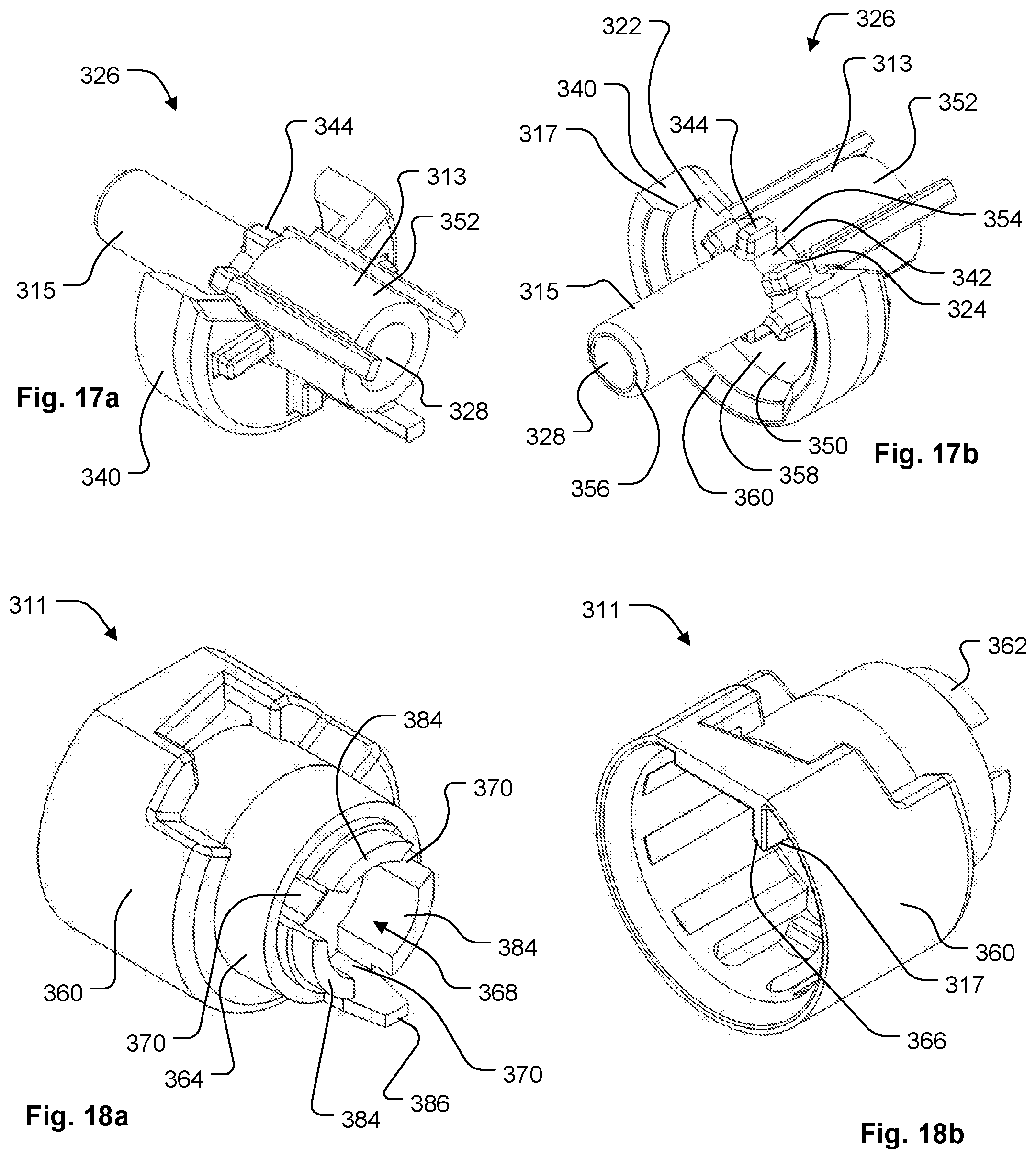
FIG. 17a is a proximal perspective view depicting a retainer of a safety coupling according to a third embodiment of the disclosure.
FIG. 17b is a distal perspective view depicting the retainer of FIG. 17a.
FIG. 18a is a proximal perspective view depicting a collar of a safety coupling according to a third embodiment of the disclosure.
FIG. 18b is a distal perspective view depicting the collar of FIG. 18a.
FIG. 19 is a perspective view depicting a second version of a safety catheter assembly according to a third embodiment of the disclosure, wherein the safety catheter assembly includes a catheter and a catheter insertion device and is in a first, ready for use position, wherein the catheter is securely connected to the catheter insertion device by a safety coupling.
FIG. 20 is a distal perspective view depicting a flangeless collar of the safety coupling depicted in FIG. 19.
FIG. 21a is a distal perspective view depicting a flangeless retainer of the safety coupling depicted in FIG. 19.
FIG. 21b is a proximal perspective view depicting the flangeless retainer of FIG. 21a.
FIG. 22 is a perspective view depicting a flangeless catheter hub of the catheter depicted in FIG. 19.
FIG. 23 is a perspective view depicting a third version of a safety catheter assembly according to a third embodiment of the disclosure, wherein the safety catheter assembly includes a catheter and a catheter insertion device and is in a first, ready for use position, wherein the catheter is securely connected to the catheter insertion device by a safety coupling.
FIG. 24 is a distal perspective view depicting a grooved collar of the safety coupling depicted in FIG. 23.
FIG. 25a is a distal perspective view depicting a grooved retainer of the safety coupling depicted in FIG. 23.
FIG. 25b is a proximal perspective view depicting the grooved retainer of FIG. 21a.
FIG. 26 is a perspective view depicting a grooved catheter hub of the catheter depicted in FIG. 23.
FIG. 27a is a perspective view depicting a safety catheter assembly according to a fourth embodiment of the disclosure, wherein the safety catheter assembly includes a catheter and a catheter insertion device and is in a first, ready for use position, and wherein the catheter is securely connected to the catheter insertion device by a safety coupling.
FIG. 27b is a perspective view depicting the catheter insertion device of FIG. 27a without the catheter to provide a better view of the safety coupling in the first, ready for use position.
FIG. 27c is a perspective view depicting the catheter insertion device of FIG. 27b, with the safety coupling in a second, safe position, wherein a sharp tip of an insertion needle of the catheter insertion device is safely housed within the catheter insertion device.
FIG. 28a is a fragmentary, side view depicting a safety catheter assembly according to a fourth embodiment of the disclosure in a first, ready for use position, wherein safety catheter assembly includes a safety coupling having a actuator, an engagement structure and a mounting collar positioned relative to one another so as to engage a catheter of the safety catheter assembly.
FIG. 28b is a fragmentary cross sectional view depicting the safety catheter assembly of FIG. 28a in a second, safe position, wherein the actuator has been shifted proximally, forcing the engagement structure away from the catheter, and thereby releasing the catheter.
FIG. 29a is a distal end view depicting the safety catheter assembly of FIG. 28a in the first, ready for use position.
FIG. 29b is a distal end view depicting the safety catheter assembly of FIG. 28b in the second, safe position.
FIG. 30a is a fragmentary, cross sectional view depicting an alternative version of a safety coupling according to a fourth embodiment of the disclosure in a first, ready for use position, wherein the catheter is securely connected to the needle housing by the safety coupling.
FIG. 30b is a cross sectional view depicting the safety catheter assembly of FIG. 30a in a second, safe position, wherein an actuator of the safety coupling has been shifted proximally, thereby releasing the catheter from the needle housing.
FIG. 31a is a distal, perspective view of a mounting collar of a safety coupling according to a fourth embodiment of the disclosure.
FIG. 31b is a proximal, perspective view of the mounting collar of FIG. 31a.
FIG. 32 is a distal, perspective view of an actuator of a safety coupling according to a fourth embodiment of the disclosure.
FIG. 33a is a distal, perspective view of an engagement structure of a safety coupling according to a fourth embodiment of the disclosure, wherein the engagement structure is in a catheter engaging closed configuration.
FIG. 33b is a top, perspective view of the engagement structure of FIG. 33a, wherein the engagement structure is in a catheter releasing open configuration.
FIG. 34a is a perspective view depicting a safety catheter assembly according to a fifth embodiment of the disclosure, wherein the safety catheter assembly includes a catheter and a catheter insertion device and is in a first, ready for use position, wherein the catheter is securely connected to the catheter insertion device by a safety coupling including a collar.
FIG. 34b is a perspective view depicting the safety catheter assembly of FIG. 34a with the collar removed to provide a better view of an actuator and an engagement structure of the safety coupling in the first, ready for use position.
FIG. 34c is a perspective view depicting the catheter insertion device and the safety coupling of FIG. 34b, with the actuator and the engagement structure of the safety coupling in a second, safe position, wherein the catheter is released from the catheter insertion device and a sharp tip of an insertion needle of the catheter insertion device is safely housed within the catheter insertion device.
FIG. 35a is a fragmentary, side view depicting a safety catheter assembly according to a fifth embodiment of the disclosure in a first, ready for use position, wherein safety catheter assembly includes a safety coupling having an actuator and an engagement structure positioned relative to one another so as to engage a catheter of the safety catheter assembly.
FIG. 35b is a fragmentary cross sectional view depicting the safety catheter assembly of FIG. 35a in a second, safe position, wherein the actuator has been shifted proximally, so as to rotate the engagement structure to release the catheter.
FIG. 36a is a distal end view depicting the safety catheter assembly of FIG. 35a in the first, ready for use position.
FIG. 36b is a distal end view depicting the safety catheter assembly of FIG. 35b in the second, safe position.
FIG. 37a is a distal, perspective view of an engagement structure of a safety coupling according to a fifth embodiment of the disclosure.
FIG. 37b is a proximal, perspective view of the engagement structure of FIG. 37a.
FIG. 38 is a distal, perspective view of a collar of a safety coupling according to a fifth embodiment of the disclosure.
FIG. 39a is a distal, perspective view of an actuator of a safety coupling according to a fifth embodiment of the disclosure.
FIG. 39b is a proximal, perspective view of the actuator of FIG. 39a.
FIG. 40 is a distal, perspective view of a catheter hub according to a fifth embodiment of the disclosure.
FIG. 41a is a perspective view depicting a safety catheter assembly according to a sixth embodiment of the disclosure, wherein the safety catheter assembly includes a catheter and a catheter insertion device and is in a first, ready for use position, wherein the catheter is securely connected to the catheter insertion device by a safety coupling.
FIG. 41b is a perspective view depicting the intravenous catheter assembly of FIG. 41a in a second, safe position, wherein the catheter is released from the catheter insertion device and a sharp tip of an insertion needle of the catheter insertion device is safely housed within the catheter insertion device.
FIG. 42a is a top view depicting the safety catheter assembly of FIG. 41a in the first, ready for use position, wherein a safety rod of the safety coupling couples the catheter to the catheter insertion device.
FIG. 42b is a top view depicting the safety catheter assembly of FIG. 42a, in the second, safe position, wherein the safety rod is pivoted to release the catheter from the catheter insertion device.
FIG. 43 is an exploded perspective view depicting a nose portion, needle housing, needle assembly, and safety rod of a safety catheter assembly according to a sixth embodiment of the disclosure.
FIG. 44 is a perspective view depicting a catheter hub coupled to a needle housing according to a sixth embodiment of the disclosure, wherein the catheter hub is coupled to the needle housing by a safety rod, and one end of the safety rod is inserted into a safety rod channel formed into a needle hub that is slidably engaged to the needle housing.
FIG. 45 is a top perspective view of the needle housing of FIG. 44.
FIG. 46a is an exploded perspective view of the needle housing and the safety rod of FIG. 44 in a first, ready for use position.
FIG. 46b is an exploded perspective view of the needle housing and the safety rod of FIG. 44 in a second, safe position, wherein the safety rod is pivoted relative to the needle housing to a catheter release position.
While embodiments of the disclosure are amenable to various modifications and alternative forms, specifics thereof are shown by way of example in the drawings and will be described in detail. It should be understood, however, that the intention is not to limit the disclosure to the particular embodiments described. On the contrary, the intention is to cover all modifications, equivalents, and alternatives falling within the spirit and scope of the disclosure as defined by the appended claims.
DETAILED DESCRIPTION
Safety catheter assemblies typically include a catheter and a catheter insertion device. The catheter is provided in a first or ready for use position, in which the catheter is connected to the catheter insertion device. In particular, the catheter, which can include a catheter hub and catheter tube, can be positioned over the needle of the catheter insertion device, with a sharp tip of the needle protruding from a distal end of the catheter. In some embodiments, a protective sheath or needle cover can be operably coupled to either the catheter or the catheter insertion device, and positioned over the sharp needle tip to inhibit unwanted needle sticks. The safety catheter assembly, which can include the catheter and catheter insertion device, can be provided for use in a sterilized and assembled state, contained within a hermetically sealed package.
To insert the catheter into the vein of a subject, a clinician first removes the safety catheter assembly from the packaging. The needle sheath is removed to expose the sharp tip of the needle that is protruding from the distal end of the catheter tube. The clinician then punctures an identified site of the patient or subject with the sharp needle tip and urges the needle forward until the needle tip enters the vein of the subject. In some versions, an initial amount of blood can pass through a lumen of the needle, and enter the catheter and/or catheter insertion device such that the clinician can view the "flashback" of the blood to confirm entry into the vein. The catheter can then be moved distally over the needle, threading the tube of the catheter into the vein of the subject as the needle is held stationary. With the catheter positioned as desired, the clinician can withdraw the needle by pulling a needle assembly of the catheter insertion device proximally away from the subject while holding the catheter generally stationary with respect to the subject. The needle assembly is pulled proximally until the needle of the catheter insertion device is separated from the catheter and safely housed within the catheter insertion device, which is referred to as the second or safe position. In the safe position, the clinician can dispose of the catheter insertion device in a sharps container.
Various example embodiments of catheters are described herein for use in accessing the vein of a subject. It is to be appreciated, however, that the example embodiments described herein can alternately be used to access the vasculature of a subject at locations other than a vein, including but not limited to the artery of a subject. It is additionally to be appreciated that the term "clinician" refers to any individual that can perform a catheter insertion procedure with any of the example embodiments described herein or alternate combinations thereof. Similarly, the term "subject," as used herein, is to be understood to refer to an individual or object in which a catheter is to be inserted, whether human, animal, or inanimate. Various descriptions are made herein, for the sake of convenience, with respect to procedures being performed by a clinician to access the vein of a subject, while the disclosure is not limited in this respect.
It is also to be appreciated that the term "distal," as used herein, refers to the direction, taking along an axis that lies parallel to the needle of a safety catheter assembly that is closest to the subject during catheter insertion. Conversely, the term "proximal," as used herein, refers to the direction lying along the axis parallel to the needle that is farther away from the subject when the catheter is inserted into the vein of the subject, opposite to the distal direction.
According to various example embodiments, the safety catheter assemblies disclosed herein can include a safety coupling. The safety coupling can be configured to couple the catheter hub to the catheter insertion device in the first or ready for use position and release the catheter hub from the catheter insertion device in the second or safe position. In some embodiments, the safety coupling can include one or more catheter hub contacts that inhibit release of a catheter from an insertion device until after the sharp needle tip of the insertion device is in a safe position, where access to the sharp needle tip is inhibited. Release of the catheter from the insertion device can occur during a catheter insertion procedure without the need to perform additional steps aside from safely retracting the needle. In this respect, the catheter can be "passively" released by a clinician to obtain "passive" safety. By way of example, the catheter can be released when a clinician pulls on a portion of the insertion device as the clinician withdraws the needle from the catheter.
The term "safety coupling," as used herein, is to be understood to refer to features of a catheter insertion device that inhibit the release of a catheter until after the catheter insertion device is in a safe position. Some or all of the features of the safety coupling can be integral with other components of the needle housing, needle assembly, and/or other components of an overall safety catheter assembly. In this respect, the term "safety coupling" does not necessarily refer to a component that is separate from the needle housing and/or needle assembly. It is to be appreciated, however, that the safety coupling can be a separate component assembly from the needle housing, according to some example embodiments.
According to various example embodiments, a catheter insertion device includes a needle lock that engages a needle assembly at a position that is proximal to the needle tip to inhibit the needle tip from being accessed after the needle is used to insert a catheter. In this manner, access to the sharp tip is inhibited with the needle in a safe position. In some embodiments, the catheter insertion device can include an actuator that is shifted proximally by interaction with a feature of the needle, such as a transition or bump, during needle withdrawal to the safe position. The proximal shifting of the actuator can cause the hub to be released from engagement by hub contacts of the insertion device after the needle reaches the safe position. One or more of the hub contacts can engage an outer surface and/or an interior surface of the catheter hub prior to being released from the insertion device.
A. First Embodiment
Referring to FIGS. 1-9, a safety catheter assembly 100 according to a first embodiment of the disclosure is depicted. FIGS. 1-8 depict a first version of the safety catheter assembly 100, while FIGS. 9a-b depict an alternative version of the safety catheter assembly 100.
As depicted in FIGS. 1 and 2a, safety catheter assembly 100 generally includes a catheter insertion device 102 and a catheter 104. FIG. 1 depicts the safety catheter assembly 100 in a first, ready for use position, while FIG. 2 depicts the safety catheter assembly 100 in a second, safe position. In the ready for use position, the catheter 104 is securely connected to the catheter insertion device 102 by a safety coupling 101. The catheter 104 is positioned over the insertion needle 106 of the catheter insertion device 104 with the sharp tip 108 extending from a distal end 110 of the catheter tube 112. In the safe position, the sharp tip 108 of insertion needle 106 can be positioned internally to an envelope of the catheter insertion device 102 to inhibit access to the sharp tip 108 by a clinician, subject, or others. The catheter 104 can be released from the catheter insertion 102 device when the catheter tube 112 of the catheter 104 is inserted at least partially within the vasculature of a subject.
Referring to FIG. 2a, the catheter 104 generally includes a catheter tube 112, a catheter hub 114, and a blood control valve 116 that lies internal to the catheter (as depicted in other embodiments, such as FIGS. 11a-b). In some versions, the blood control valve 116 can be comprised of a septum or valve to enable sealing of the fluid passageway to restrict or inhibit bodily fluid from leaking out of catheter hub 114 when catheter 104 is inserted into a patient's vein and the insertion needle 106 is removed. Various catheter hub 114 designs having septum and/or valve are disclosed in a concurrently filed application entitled "Intravenous Catheter Assembly Design,"Ser. No. 15/011,981, which is incorporated by reference herein.
The catheter tube 112 extends from a distal end 110 to a proximal end 118 where the tube is connected to a catheter hub 114 (alternately referred to as a catheter connector). The catheter tube 112 defines a lumen that provides a fluid pathway between the vein of a subject and the catheter hub 114. The catheter hub 114 includes a distal end 120 and a proximal end 122 defining a connector 124 configured to mate with other medical components that can be used in treatment of a subject, such as IV fluid supply devices, sample collection devices, extension tubes, and the like. The connector of the catheter hub 114 can be constructed to include a "luer" type connection, such as can be specified by International Standards Organization specifications ISO 594-1, ISO 594-2, and/or ISO 80369.
Referring to FIG. 2b, in some versions, catheter 104b can include a side port 125. The side port 125 can extend away from the catheter hub 114b at an oblique angle to the catheter tube 104b. The side port 125 can provide a connection point to one or more lengths of tubing 127, so that the inside of the tubing 127 is in fluid communication the lumen of catheter tube 112b.
The hollow tubing 127 can include a tubing clamp 129 and a tube connector 131. The hollow tubing 127 can be substantially transparent or translucent to enable the observation of fluid within the hollow tubing 127. The tube clamp 129 can be constructed of a resilient material that can be deformed to selectively occlude hollow tubing 127 to restrict the passage of fluid. The tube connector 131 can be configured to connect hollow tubing 127 to an IV fluid supply line. In one version, the tube connector 131 is a luer lock. In another version, the tube connector 131 is a needle-free connector, for example the connector described in U.S. Pat. No. 7,713,248 (depicting a needle-free connector marketed by ICU Medical, Inc. under the CLAVE trademark), which is hereby incorporated by reference herein.
The catheter hub 114b can include one or more wings 133 that extend radially from the catheter hub 114b. The one or more wings 133 can generally extends outwardly from the central axis of the catheter hub 114b, so as to provide an adequate gripping surface for the clinician, as well as an extended surface for aid in securing the catheter hub 114b in place on the subject. In one version, the one or more wings 133 are integrally molded onto a portion of the catheter hub 114b. In another version the wings 133 are coupled to the catheter hub 114b via a collar 135 or the like that at least partially surrounds the catheter hub 114b.
Catheter 104 or 104b, or versions thereof, can be used in conjunction with this embodiment as well as any of the other embodiments or versions of the embodiments described or referenced by this disclosure.
The catheter insertion device 102 includes a needle assembly 128 that is movable with respect to a needle housing 126 from a first, ready for use position (as depicted in FIG. 1), to a second, safe position (as depicted in FIG. 2a). As best depicted in FIGS. 3a-c, the needle assembly 128 can include an insertion needle 106 operably coupled to a needle hub 132.
The needle 106 can includes an elongate, cylindrically shaped metal structure defining a lumen that extends from a sharp distal end tip 108 to a proximal end 130. The sharp distal end tip 108 can be constructed and arranged to pierce the skin of a subject during catheter insertion. The needle can include a transition 166 or needle bump that has a different cross sectional size and/or shape than portions of the needle that lie proximal to the transition. Needle transitions (alternately referred to as needle or cannula bumps) can be created by crimping opposed sides of the needle 106, or otherwise disrupting the structure of the needle 106, so that the outer surface of the needle 106 extends to a larger radial position than other portions of the needle 106, as measured from the center of the needle axis. Transitions can be formed differently, according to alternate embodiments, such as by adding material to the exterior of the needle, among other ways. The proximal portion 130 of the needle can be connected to the needle hub 132.
The needle hub 132 can be connected to a needle grip 134 positioned on the exterior of the needle housing 126 when assembled thereto for access by a clinician. The needle hub 132 and needle grip 134 can be operably coupled to one another by a protuberance 136 that can be formed from the same unitary structure as the needle grip 134 and the needle hub 132.
In one version, the needle assembly 128 can be constructed to provide a visual indication of flashback when the sharp tip 108 of the needle 106 enters the vein of a subject. In this version, the needle hub 132 includes a flash chamber 160, wherein the needle lumen is in fluid communication with a flash chamber 160. When the sharp tip 108 enters a vein during catheter insertion, blood enters the needle lumen from the vein and flows proximally through the needle 106 and into the flash chamber 160. The flash chamber 160 can be sealed at one end by a flash plug 162. The flash plug 162 can be made of an air permeable, hydrophilic material that enables the passage of air, but that inhibits the passage of liquid. Air that resides in the needle lumen and flash chamber 160 is therefore pushed through the flash plug 162 by the incoming blood, until the blood reaches the flash plug 162 or is otherwise stopped. The needle hub 132, or portions thereof, can be constructed of a clear or translucent material to enable a clinician to view the presence of blood within the flash chamber. In this respect, the clinician can be alerted when the needle has entered the vein of the subject by the presence of blood in the flashback chamber.
In some embodiments, flash chamber 160 can further include a diagnostic sampling port configured to enable selective access to fluid contained within flash chamber 160. Various needle assemblies having diagnostic sampling ports are disclosed in a concurrently filed application entitled "Needle Assembly with Diagnostic Analysis Provisions,"Ser. No. 15/012,059, which is incorporated by reference herein.
In some versions, features of the needle assembly 128, other than the flashback chamber 160, can provide an indication that the needle tip 108 has entered the vein of a subject. For example, the needle can include a notch 164. In this version, blood flow enters the needle lumen when the sharp tip 108 enters the vein. As blood flows proximally in the needle lumen, some blood passes thorough the notch 164 and into the annular space that lies between the exterior of the needle 106 and the interior of the catheter tube 112. The presence of blood in the annular space can be viewed by a clinician through clear or translucent portions of the catheter tube 112, providing an indication that the needle tip is present in a vein.
As best depicted in FIGS. 2a and 4a-b, the needle housing 126 can have a generally cylindrical, elongate body 142 that extends from a proximal end 144 to a distal end 146. A longitudinal slot 150 can be formed along an underside of the needle housing 126 and extend from a proximal slot end 152 near the proximal end 144 of the needle housing 126 to a distal slot end 154 near the distal end 146 of the housing 126.
The needle hub 132 can be slideably coupled to the needle housing 126. For example, the needle hub 132 can have a "C" shaped cross section conformed to fit around the outer surface of the needle housing 126 in a manner that inhibits the needle hub 132 from readily separating from the needle housing 126, yet enables the needle hub 132 to slide along the longitudinal axis of the needle housing 126 with minimal resistance. In one version, the slot 150 can slidably receive the protuberance 136 of the needle assembly 128, with the needle grip 134 positioned outside of the needle housing 126 and at least a portion of the needle hub 132 and needle 106 positioned internally to the needle housing 126, thereby at least partially housing these features. Accordingly, the needle hub 132 can be configured to slide along a groove 150 to restrict the needle hub 132 from rotating about the longitudinal axis of the needle housing 126. The protuberance 136 slideably received within the groove 150, thereby enables linear movement of the needle hub 132 substantially parallel to the longitudinal axis of the needle housing 126, but restricts the rotational movement of the needle hub 132 relative to the needle housing 126.
The slot 150 can guide the needle assembly 128 in motion with respect to the needle housing 126 between the first, ready for use position (as depicted in FIG. 4a) and the second, safe position (as depicted in FIG. 4b). In the first, ready for use position, a portion of the needle 106 extends from needle housing 126, such that the sharpened tip 108 of the needle 106 protrudes beyond the needle housing 126. In the second, safe position, the needle 106 is withdrawn, and the sharpened tip 108 is housed within the needle housing 126 in a manner intended to reduce or eliminate the likelihood of an inadvertent needle stick.
After positioning in the second, safe position, return movement of the needle assembly 128 back toward the first, ready for use position can be inhibited by a needle lock 156. The needle lock 156 can thus be configured to interlock the needle hub 128 to the needle housing 132 in the second, safe position. In one version, the needle lock 156 can be positioned on a proximal portion of the housing 126 at the proximal slot end 152 to engage the protuberance 136. Several different types of locking mechanisms can be used for this purpose. For example, in one version, the slot 150 of the needle housing 126 can have a bottleneck 156 defined in it, where the bottleneck portion of the groove 150 generally has a narrower width than the rest of the groove 150. Protuberance 136 of needle hub 136 can be triangular or wedge-like in shape where the apex of the wedge faces the bottleneck 156 when in the first, ready for use position. When an external force is applied to the needle hub 136 in an effort to slide it into the second, safe position, the apex of the wedge of the protuberance 136 comes into contact with the bottleneck 156. The bottleneck 156, which can have a width narrower than that of the protuberance 136 will initially resist movement of the protuberance 136 through the bottleneck 156. However, with sufficient force the wedge-shape protuberance 136 will cause the bottleneck 156 to temporarily deform, thereby enabling the protuberance 136 to pass through the bottleneck 156. For example, in one version, the interaction between the wedge-shape protuberance 136 and the bottleneck 156 will create an audible "click" sound when the protuberance 136 to passes through the bottleneck 156. Thereafter the protuberance 136 will be unable to pass back through the bottleneck 156 in the opposite direction, and the needle 106 will be locked in the second, safe position relative to the needle housing 126.
In some versions, the catheter insertion device 102 can include an end cap 138 (as depicted in FIGS. 1-2a). The end cap 138 can be connected to the needle grip 134 and/or needle hub 132, thereby covering the proximal end of the needle housing 126. The end cap 138 can have a proximal end 140 that can provide a surface against which a clinician can press during a catheter insertion procedure, as discussed herein.
At the distal end 146 of the needle housing 126, the needle assembly 128 can engage a distal stop 158 to inhibit the needle assembly 128 from moving distally beyond the first, ready for use position with respect to the needle housing 126. The distal stop 158 can include a proximally facing portion of a safety coupling 101 that engages a distal end of the needle grip 134 to inhibit further distal movement of the needle assembly 128. Alternate distal stops are also contemplated, including stops formed by interaction between the protuberance and the distal end of the slot, among others. The safety coupling 101 can be positioned near the distal end 146 of the needle housing 126.
As best depicted in FIGS. 5a-8, the safety coupling 101 can include a nose 115, a pair of engagement arms 172 each having an exterior hub contact 117, and an actuator 113. The safety coupling 101 is shiftable between a first, ready for use position (as depicted in FIGS. 1, 5a, and 5b), wherein the actuator 113 is positioned to hold the external hub contacts 117 in engagement with an external surface 178 of the catheter hub 114, thereby inhibiting release of the catheter hub 114 from the catheter insertion device 102, and a second, safe position (as depicted in FIGS. 2, 6a, and 6b), wherein the actuator 113 is shifted proximally, into a disengaged position that enables the engagement arms 172 to move or pivot laterally away from the catheter hub 178. In particular, when the needle 106 is pulled proximally to remove the needle 106 from the catheter 104, the needle transition 166 can contact the actuator 113, thereby enabling the needle 106 to shift the actuator 113 of the safety coupling 101 in the proximal direction. Thus, proximal movement of the actuator 113 releases the exterior hub contacts 117 from engagement with the catheter hub 178 so that the catheter 104 can be removed from the catheter insertion device 102.
In the first, ready for use position, the safety coupling 101 is configured with the actuator 113 in the distal, engaged position. The catheter hub 114 is positioned over the nose 115 and in contact with the hub plate 180. The actuator arms 182 hold the engagement arms 172 and exterior hub contacts 117 in engagement with the catheter 104. This occurs with the engagement arms 172 being forced inwardly by a portion of the interior wall 184 of an arm box portion 186 of an actuator arm 182. The distal portion of each engagement arm 172 is received into the distal portion receiver 171 of an arm box portion 186. The actuator body 188 contacts the hub plate 180 of the nose 115 to inhibit distal movement of the actuator 113. Contact between the actuator arms 182 and the engagement arms 172 can also inhibit further distal movement of the actuator 113 from the distal, engaged position. The distal end of the needle grip 134, which lies at a larger diameter than the actuator arms, inhibits the actuator arms 182 from being accessed and moved proximally, prior to the needle assembly also being moved proximally.
In the second, safe position, the actuator 113 is shifted proximally to a disengaged position. Proximal movement of the actuator 113 also causes the actuator arms 182 to move proximally. When the actuator arms 182 move proximally, the engagement arms 172 pivot outwards, disengaging exterior hub contacts 117 from an exterior surface 178 of the catheter hub 114. This disengages the catheter 104 from the safety coupling 101 and enables the catheter 104 to be removed therefrom. It is to be appreciated that the external hub contacts 117, or other portions of the safety coupling 101, can remain in contact with the catheter hub 114 while being disengaged therefrom.
As best depicted in FIG. 7, the nose 115 can include a body 192, a tapered extension 194, a hub plate 180, and a mounting collar 196 for the overall safety coupling 101. The nose 115 can be connected to the distal end of the needle housing 126 with the mounting collar 196 positioned internally to the needle housing 126 and the hub plate 180 abutting the distal end 146 of the needle housing 126. The tapered extension 194 can extend distally from the hub plate 180 and can be sized and shaped to be received within the catheter hub 114. In some version, tapered extension 194 can contact a blood control valve within the catheter hub 114 to provide guidance during catheter 104 removal. Contact between the tapered extension 194 and a blood control valve can also provide a seal to contain flashback blood that lies between the needle 106 and catheter tube 112.
A passage 198 can extend through the nose 115, including the mounting collar 196, hub plate 180 and tapered extension 194. The passage 198 can be sized to enable the needle 106, including the needle transition or bump 166, to pass without restriction from the ready for use position to the safe position. When the needle assembly 128 is in the safe position, the sharp needle tip 108 can be positioned inside of the passage 198. The blunt distal end of the tapered extension 194 can contact surfaces that are brought into contact with the distal end of the catheter insertion device 102 instead of the sharp needle tip 108. In this manner, unwanted needle sticks are inhibited. The needle lock 156, when engaged, inhibits the sharp tip 108 from emerging from the nose 115, as discussed herein.
The engagement arms 172 can extend outwardly and distally from hub plate 180 and can be connected to the hub plate 180 by resilient members 141. In one version, resilient members 141 are leaf springs. Engagement arms 172 can be formed from a common unitary structure with the nose 115, although other configurations are also contemplated with the nose and the engagement arms formed from separate components. Each engagement arm 172 has a longitudinal portion, including a distal portion 143 and proximal portion 145 that lies generally parallel to the needle 106 when the catheter insertion device 102 is in the ready for use position. A hub retention finger 195 is arranged orthogonally to the distal portion 143 of each engagement arm 172 and extends laterally inward, ending in an external hub contact 117. The proximal portion 145 extends proximally of the resilient member 141 that connects the engagement arm 172 to the nose 115. The distal portion 143 can be substantially longer than proximal portion 145, although alternate configurations are also contemplated.
The external hub contacts 117 can include both a laterally inward facing surface 175 and a proximally facing surface 177. The laterally inward facing 175 and proximally facing surface 177 can act together to hold the catheter 104 in engagement to the catheter insertion device 102. The laterally facing surface 175 conforms to the corresponding surface of the catheter hub 114 and can be concave in shape. The proximally facing surface 177 can also conform to the corresponding surface of the hub 114, which can include a rim or flange 147 that extends circumferentially about and laterally away from the proximal end 122 of the catheter hub 114. In alternate versions, the rim 147 can also include a rib or luer thread 149 that can be contacted by an exterior hub contact 117 of an engagement arm 172.
The resilient members 141 connect the engagement arms 172 to the nose 115 and enable the engagement arms 172 and exterior hub contacts 117 to move out of engagement with the catheter hub 114 when the actuator 113 is in the proximal, disengaged position. The resilient members 141 can have a curved structure that extends between the juncture of distal portion 143 and proximal portion 145 to a proximal aspect of hub plate 180. The resilient members 141 can act to bias the engagement arms 172 and external hub contacts 117 away from the catheter hub 114 (as depicted FIGS. 2, 6a, 6b, and 7). In this respect, the resilient members 141 and the external hub contacts 117 are disengaged from the catheter 104 merely by the actuator moving to enable the second, safe position. The resilient members 141 bias or urge the external hub contacts 117 away from the hub 114. The resilient members 141 can be formed of the same unitary structure as the nose 115 and engagement arms 172, or can be formed separately.
Some versions include a pair of engagement arms 172 that are positioned on lateral sides of the catheter hub 114 when the safety catheter assembly 100 is positioned for catheter insertion in the ready for use position. Placement of the engagement arms 172 on the lateral sides can promote easier separation of the catheter 104 from the catheter insertion device 102. In other versions, the engagement arms 172 can be oriented differently with respect to the catheter hub 114, as the present disclosure is not limiting in this respect. For example, safety couplings 101 can include different numbers of engagement arms 172, including as few as one engagement arm 172 or three or more engagement arms 172, according to other versions.
As best depicted in FIG. 8, the actuator 113 can include an actuator body 188 and actuator arms 182. The actuator arms 182 can contact the engagement arms 172 in a manner that engages or holds the external hub contacts 117 against the catheter hub 114 to inhibit catheter 104 release when the actuator 113 is shifted distally. The actuator 113 generally includes an actuator body 188 having a central portion and a pair of actuator arms 182. The actuator arms 182 can include a first arm and a second arm; however, alternate versions can include a lesser or greater number of actuator arms 182, particularly where other versions include a different number of engagement arms 172. The actuator 113 and actuator arms 182 can be formed from a common unitary structure. According to alternate versions, the actuator arms 182 and nose 115 are features of separate components rather than a unitary structure.
The actuator 113 includes a central portion having ring collar 151. The ring collar 151 generally includes cylindrical portion 153 and frustoconical portion 155. The ring collar 151 defines an actuator needle passage 157 therethrough. The needle passage 157 includes narrow portion 159 and wide portion 161. The narrow portion 159 is proximal to the wide portion 161 and is sized to receive the needle 106 in tight fitting apposition therethrough. The wide portion 161 is slightly wider than narrow portion 159. That is, the diameter or cross sectional dimension of the actuator needle passage 157 is greater in at least portions of the wide portion 161 than in the narrow portion 159. The transition between the wide portion and the narrow portion defines a needle abutment 163 that is shaped and sized to inhibit the passage of the needle transition or needle bump 166.
Proximal movement of the needle 106 causes the needle transition 166 to contact and engage the needle abutment 163 when the needle assembly 128 is moved near or within the safe position. This engagement between the needle transition 166 and needle abutment 163 enables the actuator 113 to be shifted proximally by movement of the needle 106 during needle withdrawal. Actuator arms 182 are moved proximally with the actuator shift to release the engagement arms 172 and hub contacts 117 from engagement with the catheter 104 so that the catheter can be released after the needle assembly 128 reaches the safe position. It is to be appreciated that FIGS. 1-8 depict but one configuration of an actuator and needle abutment, and that other configurations are also contemplated. By way of non-limiting example, alternate versions can lack a needle passage 157 having a wide portion 161 and a narrow portion 159. In such versions, the needle abutment 163 can be formed from a distally facing surface of the actuator 113 that contacts a needle transition 166.
The actuator arms 182 can be similar in structure to one another and generally can include a radial portion 165 and an arm box portion 186. The radial portion 165 extends outwardly from the cylindrical portion 153 and supports the arm box portion 186 at a peripheral end thereof. The arm box portion 186 generally includes an exterior wall 167 and side walls 169. The side walls 169 can be substantial mirror images of each other. Within the exterior wall 167 and side walls 169 is distal portion receiver 171. The distal portion receiver 171 is sized and shaped to receive the distal portion of the engagement arm 172. In some versions, the arm box portion 186 further includes an exterior wall 167 and side walls 169 defining the distal portion receiver 171 into which the distal portion 143 of the at least one engagement arm 172 is receivable.
The actuator 113 can be guided by various features that interact with other components of the insertion device 102 as the actuator 113 is shifted proximally. In some versions, the radial portion 165 of the actuator arm 182 is captured by a slot formed in a needle housing 126 of the safety catheter assembly 100. The cylindrical portion 153 of the actuator 113 can be sized for sliding contact with the inner surface of the needle housing 126. Interaction between side walls 169 of the actuator arms 182 (or other portions of the actuator arms) and the engagement arms 172 can also provide guidance and stability as the actuator 113 is shifted proximally.
In one version, at least a portion of the actuator 113 is located proximal to the nose 115 and is abuttable to an interior of the proximal portion 145 of the at least one engagement arm 172. The actuator 113 can be shiftable between a distal position (as depicted in FIG. 9a), wherein the actuator 113 holds the at least one engagement arm 172 in a first, engaged position by inhibiting inward movement of the proximal portion 145 of the at least one engagement arm 172 and a proximal position (as depicted in FIG. 9b), wherein the proximal portion 145 of the at least one engagement arm 172 can move inwardly and the distal portion 143 of the at least one engagement arm 172 is released from the catheter hub 114 and the catheter hub 114 can be removed from the nose 115.
In operation, safety catheter assembly 100 can be removed from the provided packaging. A needle sheath can be removed from the safety catheter assembly 100. The clinician can select and prepare an insertion site for catheter placement. In some versions, safety catheter assembly 100 can include at least one of a self-contained antiseptic swab, and a tourniquet for treatment and/or preparation of the insertion site. Various safety catheter assemblies having self-contained antiseptic swabs and/or tourniquets are disclosed in a concurrently filed application entitled "Antiseptic Sheath with Site Preparation Provisions,"Ser. No. 15/012,032, which is incorporated by reference herein.
After preparation of the insertion site, the clinician can puncture the selected site of a subject with the sharp needle tip 108 and urge the needle 106 forward until the needle tip 108 enters the vein of the subject. To accomplish this, the clinician can hold the safety catheter assembly 100 with a finger and thumb on opposed sides of the needle grip 134 as the needle is urged into the subject. The clinician can optionally position the palm of their hand against a proximal end 140 of the needle assembly (e.g., the end cap 138). Once flashback of blood is witnessed to confirm entry of the needle into the vein, the clinician can stop moving the needle forward.
The clinician can advance the catheter 104 after the needle tip 108 initially enters the vein. To accomplish this, the needle grip 134 is held stationary to inhibit further distal movement of the needle 108. The clinician moves the needle housing 126 distally to urge the catheter 104 forward, over the stationary needle, and further into the vein of the subject. The clinician can push a tab 179 of the needle housing 126 forward with their finger to do this. Forward movement of the needle housing is stopped once the catheter is positioned at a desired depth in the subject. Catheter advancement into the subject moves the needle housing 126 and catheter 104 distally, relative to the needle 108 and needle assembly 128, without placing the needle assembly 128 in the first, safe position and without shifting the actuator 113 proximally to release the catheter 104 from the catheter insertion device 102.
The needle housing 126 and catheter 104 are held generally stationary relative to the subject as the needle assembly 128 is pulled proximally to withdraw the needle 108 from the subject and the catheter 104. The clinician can pull the needle assembly 128 with their finger and thumb in the same orientation on the needle grip 134 as during needle insertion, without having to reorient their grasp. Alternately, the clinician can reorient their grip and/or grab other portions of the needle assembly 128, including the end cap 138, to perform needle withdrawal. According to either approach, the catheter 104 is released from the insertion device 102 as a part of the needle 106 withdrawal motion without the clinician performing additional steps. This occurs when the needle transition 166 contacts the needle abutment 163 of the actuator 113 to enable the needle assembly 128 to shift the actuator 113 proximally from the engaged position to the disengaged position. The needle tip 108 is also positioned internally to the insertion device 102, where access to the tip 108 is inhibited, as a normal part of the needle withdrawal motion without the clinician performing additional steps.
The clinician can hold the catheter hub 114 stationary to inhibit the catheter 104 from being withdrawn from the subject as the needle 106 is withdrawn. This can be accomplished, according to one example approach, by holding the catheter hub 114 in position with one hand and pulling the needle assembly 128 away from the catheter hub 114 with the opposite hand. This can be referred to as a two-hand technique. According to another example approach, the clinician withdraws the needle 106 by pulling the needle grip 134 proximally with a middle finger and thumb of one hand. The needle housing 126 can be held stationary with the index finger of the same hand, such as by being placed on the tab 179 of the needle housing 126.
Referring to FIGS. 9a-b, another version of the safety coupling 101 according to a first embodiment of the disclosure is depicted. FIG. 9a depicts the coupling 101 in a ready for use position with the actuator 113 in a distal, engaged position and a catheter hub 114 secured thereto. FIG. 9b depicts the safety coupling 101 as configured when the needle assembly 128 (not shown) is held in the safe position by the needle lock 156 and the actuator 113 is positioned proximally, in the disengaged position.
In this version, the safety coupling 101 is constructed to engage the catheter 104 with an exterior hub contact 117 with a single engagement arm 172 and an interior hub contact 181 formed in the nose 115. Together, the exterior hub contacts 117 and interior hub contacts 181 retain the catheter 104 securely engaged to the catheter insertion device 102 until after the actuator 113 is shifted proximally and needle assembly is in the safe position. The exterior and interior hub contacts 117, 181 can still touch the hub 114 in the safe position. The catheter 104, however, can be freely removed from the catheter insertion device 102, as in the various other example embodiments and versions described herein.
The interior hub contact 181 is formed at the junction between the base 183 of the nose 115 and the hub plate 180. The interior hub contact 181 is shaped and sized to receive a proximal interior portion 185 of the catheter hub 114 in a slip fit type arrangement. This fit can include a taper that is oriented similarly to that of the tapered nose. Alternately, the interior hub contact 181 can lack a taper.
The mounting collar 196 can include a body portion 187 and a mounting plate 189. The mounting plate 189 can be located at a proximal end of the collar 196 and can be received by the distal end 146 of the needle housing 126. The mounting plate 189 can include a central aperture 191 that enables passage of the needle 106. The body portion 187 of the mounting collar 196 can extend between the mounting plate 189 and the hub plate 180 of the nose 115. The catheter hub 114 can abut the hub plate 180, when assembled to the safety coupling 101. The mounting plate 189 can provide a proximal stop for the actuator 113, as discussed herein.
The exterior hub contact 117 can be shaped to promote both catheter 104 retention and separation from the catheter insertion device 102. The exterior hub contact surface 117 of the engagement arm 172 can be angled so that the catheter hub 114 can urge the contact 117 and engagement arm 172 laterally away from the catheter hub 114 as the catheter insertion device 102 moves away from the catheter 104. The single engagement arm 172 can be positioned on an underside of the insertion device 102. In use, the clinician can promote separation of the catheter 104 from the catheter insertion device 102 by moving the proximal end of the insertion device 102 away from the subject. This can place the insertion device 102 and the engagement arm 172 at an angle that pushes the external hub contact away from the catheter hub.
The actuator 113 can be positioned internally to the engagement arm 172 to retain the external and internal hub contacts 117, 181 in cooperative engagement with the catheter 104. In the first, ready for use position (as depicted in FIG. 9a), the actuator 113 lies between the proximal portion 122 of the engagement arm 172 when the actuator 113 is in the distal, engaged. In the second, safe position (as depicted in FIG. 9b), the actuator 113 is shifted proximally, out from in between the engagement arm 172 and other portions of the insertion device, to enable the engagement arm and external hub contact 117 to pivot away from the catheter hub 114. This occurs as the needle transition 166 contacts the needle abutment 163 of the actuator 113 to shift the actuator 113 proximally when the needle assembly 128 is moved to the safe position during needle withdrawal. In some versions, positioning the engagement arm 172 over the actuator 113, can inhibit inadvertent actuator 113 movement that might otherwise enable for catheter 104 release.
The engagement arm 172 can be connected to the nose 115 by a living hinge 193 that enables the distal portion 143 of the engagement arm 172, including the external hub contact 117, to pivot away from the catheter hub 114. The living hinge 193 is constructed so that the distal portion 143 and proximal portion 145 are generally unbiased either toward or away from the catheter hub 114. The external hub contact 117 is engaged to the catheter hub 114 by the actuator 113 in the ready for use position. The distal portion 143 of the engagement arm 172 is moved away from the catheter hub 114 as the catheter 104 is pulled distally away from the catheter insertion device 102, after the actuator 113 has been shifted proximally to the disengaged position. It is to be appreciated that, according to other versions, the engagement arm 172 can be biased toward or away from the catheter hub 114 by a resilient member or other structure.
B. Second Embodiment
Referring to FIGS. 10a-14b, a safety catheter assembly 200 according to a second embodiment of the disclosure is depicted. FIGS. 10a, 10b, and 11a depict the safety catheter assembly 200 in the first, ready for use position. FIGS. 10c and 11b depict the safety catheter assembly 200 in the second, safe position. FIGS. 12a-14b depict various components of the safety catheter assembly 200 in greater detail.
The safety catheter assembly 200 generally includes a safety coupling 201 including a collar 211, an actuator 213, a nose 215, a catheter hub 114, and a needle 106. The collar 211 is positioned about a proximal portion 122 of the catheter hub 114, and a safety coupling 201. The collar 211 is omitted from FIGS. 10b and 10c to provide an improved view of other features. The collar 211 can be positioned about the proximal portion 122 of the catheter hub 114, the engagement arm 220, and the actuator 213. In this respect, the collar 211 can inhibit access to these components or portions thereof.
The safety coupling 201 is constructed to engage the catheter 104 with an engagement structure 222 that includes a single engagement arm 220. The safety coupling 201 generally includes a nose 215, an actuator 213 and an engagement arm 220. The engagement arm 220 includes external hub contacts 217 that cooperate with an interior hub contact 224 formed in the nose 215, as depicted in FIGS. 10b and 11a, wherein the insertion device 102 is in the ready for use position with the actuator 213 shifted to a distal, engaged position. When the needle assembly 128 of the insertion device 102 is in the safe position (as depicted in FIGS. 10c and 11b), the actuator 213 is shifted to a proximal, disengaged position. In the safe position, the exterior hub contacts 217 of the engagement arm 220 are released from engagement with the catheter hub 114, thereby enabling the catheter 104 to be removed from the insertion device 102.
As best depicted in FIGS. 12a and 12b, the collar 211 is a generally unitary structure formed of plastic or another material of sufficient rigidity and generally presents a cylindrical portion 241, a flat portion 242 and a cupola portion 243. The flat portion 242 can be located at the bottom of the cylindrical portion 241, while the cupola portion 243 can extend upwardly from the cylindrical portion.
The cylindrical portion 241 of the collar 211 can generally present a cylindrical outer surface, with nose bushings 244 positioned internally that are dimensioned to receive and support the nose 215 therein, and structured to urge the engagement arm 220 inwardly. The nose bushings 244 can present a curved lead supporting surfaces 245, upper flats 246 and lower flats 247. The flat portion 242 can generally include a lower plate 248 extending between the nose bushings 244. The cupola portion 243 can generally be formed of a cupola roof 249 and two side walls 250. The cupola portion 243 can be sized and shaped to receive the roof portion 254 of the actuator 213 therein. The collar 211 can also present a base portion 239 and a mounting collar 225. The base portion 239 and mounting collar 225 together can define an actuator receiving passage therethrough. The actuator receiving passage 251 can be sized and shaped to receive the actuator 213 therein.
As best depicted in FIGS. 13a-b, the actuator 213 can be a unitary structure formed out of plastic or another suitable material of sufficient rigidity. The actuator 213 can be located within the collar 211, and can be axially shiftable between a distal position (as depicted in FIG. 11a) and a proximal position (as depicted in FIG. 11b). The actuator 213 can include an actuator body 226 and an actuator arm 227. The actuator body 226 can be a substantially cylindrical body that defines an actuator needle passage 228 therethrough and cylindrical surface outside thereof. The body portion 226 of the actuator 213 can be sized and shaped to be received substantially within the nose 215. The needle passage 228 can pass axially through the cylindrical actuator body 226 and can generally present a wide portion 230, a narrow portion 232 and funnel portion 234. The wide portion 230 can be located most distally followed by narrow portion 232 followed by pro
D00000
D00001
D00002
D00003
D00004
D00005
D00006
D00007
D00008
D00009
D00010
D00011
D00012

D00013

D00014

D00015

D00016
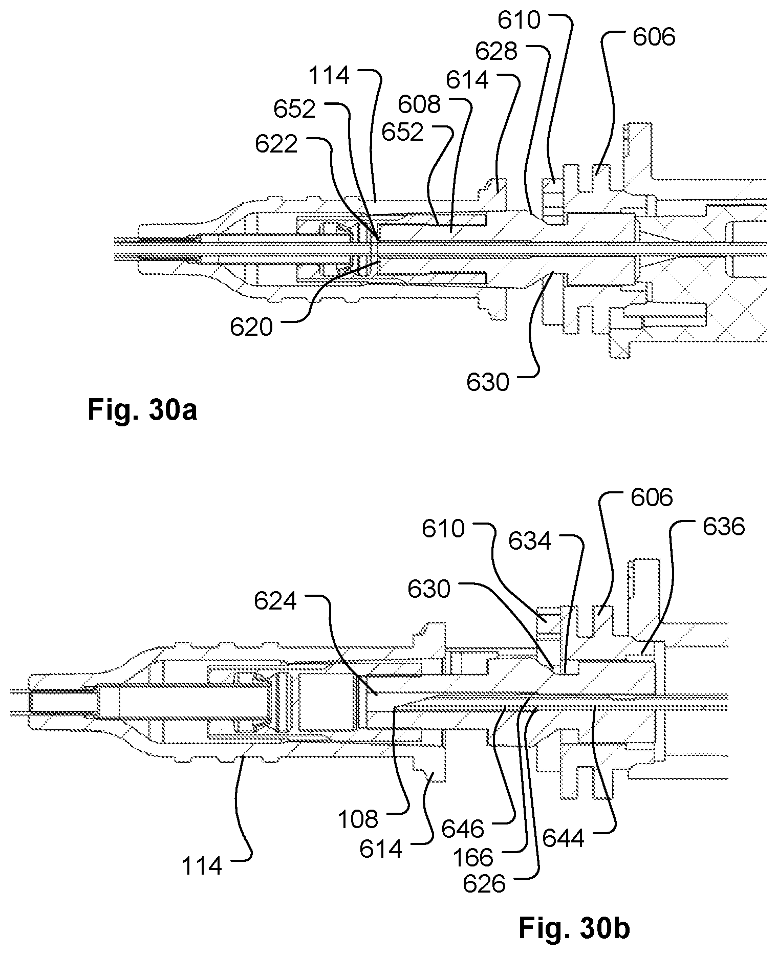
D00017

D00018

D00019

D00020

D00021

D00022

D00023

D00024

D00025

D00026

XML
uspto.report is an independent third-party trademark research tool that is not affiliated, endorsed, or sponsored by the United States Patent and Trademark Office (USPTO) or any other governmental organization. The information provided by uspto.report is based on publicly available data at the time of writing and is intended for informational purposes only.
While we strive to provide accurate and up-to-date information, we do not guarantee the accuracy, completeness, reliability, or suitability of the information displayed on this site. The use of this site is at your own risk. Any reliance you place on such information is therefore strictly at your own risk.
All official trademark data, including owner information, should be verified by visiting the official USPTO website at www.uspto.gov. This site is not intended to replace professional legal advice and should not be used as a substitute for consulting with a legal professional who is knowledgeable about trademark law.