Balloon atherectomy catheters with imaging
Simpson , et al. Fe
U.S. patent number 10,548,478 [Application Number 14/424,277] was granted by the patent office on 2020-02-04 for balloon atherectomy catheters with imaging. This patent grant is currently assigned to Avinger, Inc.. The grantee listed for this patent is Avinger, Inc.. Invention is credited to Mark W. Askew, Stephen C. Davies, Priyanshu Gupta, Manish Kankaria, Theodore W. Ketai, Wendy N. Lam, Charles W. McNall, John B. Simpson, Peter H. Smith, Maegan K. Spencer, Nicholas J. Spinelli, Kent C. B. Stalker, Michael Zung.


View All Diagrams
| United States Patent | 10,548,478 |
| Simpson , et al. | February 4, 2020 |
Balloon atherectomy catheters with imaging
Abstract
An atherectomy catheter includes an elongate flexible catheter body, a cutter near the distal end of the catheter body, a drive shaft connected to the cutter and extending within the catheter body, an imaging element near the distal end of the catheter body and an imaging shaft connected to the imaging element and extending within the catheter body. The cutter and the imaging element are mechanically isolated, and the drive shaft is configured to be axially translated relative to the imaging shaft and the catheter body.
| Inventors: | Simpson; John B. (Woodside, CA), Gupta; Priyanshu (Palo Alto, CA), Zung; Michael (San Carlos, CA), Lam; Wendy N. (San Jose, CA), Spencer; Maegan K. (Emerald Hills, CA), Smith; Peter H. (Pacifica, CA), Davies; Stephen C. (El Dorado Hills, CA), Spinelli; Nicholas J. (San Mateo, CA), McNall; Charles W. (Cottonwood Heights, UT), Ketai; Theodore W. (San Francisco, CA), Kankaria; Manish (Fremont, CA), Askew; Mark W. (San Francisco, CA), Stalker; Kent C. B. (San Marcos, CA) | ||||||||||
|---|---|---|---|---|---|---|---|---|---|---|---|
| Applicant: |
|
||||||||||
| Assignee: | Avinger, Inc. (Redwood City,
CA) |
||||||||||
| Family ID: | 50237522 | ||||||||||
| Appl. No.: | 14/424,277 | ||||||||||
| Filed: | March 15, 2013 | ||||||||||
| PCT Filed: | March 15, 2013 | ||||||||||
| PCT No.: | PCT/US2013/032494 | ||||||||||
| 371(c)(1),(2),(4) Date: | February 26, 2015 | ||||||||||
| PCT Pub. No.: | WO2014/039099 | ||||||||||
| PCT Pub. Date: | March 13, 2014 |
Prior Publication Data
| Document Identifier | Publication Date | |
|---|---|---|
| US 20150208922 A1 | Jul 30, 2015 | |
| US 20180368688 A9 | Dec 27, 2018 | |
Related U.S. Patent Documents
| Application Number | Filing Date | Patent Number | Issue Date | ||
|---|---|---|---|---|---|
| 13175232 | Jul 1, 2011 | 9345510 | |||
| 61697743 | Sep 6, 2012 | ||||
| 61360886 | Jul 1, 2010 | ||||
| 61468396 | Mar 28, 2011 | ||||
| 61492693 | Jun 2, 2011 | ||||
| Current U.S. Class: | 1/1 |
| Current CPC Class: | A61B 5/0066 (20130101); A61B 5/0084 (20130101); A61B 90/361 (20160201); A61B 17/320725 (20130101); A61B 17/320758 (20130101); A61B 17/320783 (20130101); A61B 2017/22071 (20130101); A61B 5/6852 (20130101); A61B 2017/320791 (20130101); A61B 2017/22061 (20130101); A61B 2090/3735 (20160201) |
| Current International Class: | A61B 5/00 (20060101); A61B 17/3207 (20060101) |
References Cited [Referenced By]
U.S. Patent Documents
| 3908637 | September 1975 | Doroshow |
| 4178935 | December 1979 | Gekhaman et al. |
| 4487206 | December 1984 | Aagard |
| 4527553 | July 1985 | Upsher |
| 4552554 | November 1985 | Gould et al. |
| 4611600 | September 1986 | Cohen |
| 4621353 | November 1986 | Hazel et al. |
| 4639091 | January 1987 | Huignard et al. |
| 4654024 | March 1987 | Crittenden et al. |
| 4686982 | August 1987 | Nash |
| 4691708 | September 1987 | Kane |
| 4771774 | September 1988 | Simpson et al. |
| 4841977 | June 1989 | Griffith et al. |
| 4857046 | August 1989 | Stevens et al. |
| 4920961 | May 1990 | Grossi et al. |
| 4926858 | May 1990 | Gifford, III et al. |
| 5000185 | March 1991 | Yock |
| 5018529 | May 1991 | Tenerz et al. |
| 5041082 | August 1991 | Shiber |
| 5047040 | September 1991 | Simpson et al. |
| 5085662 | February 1992 | Willard |
| 5099850 | March 1992 | Matsui et al. |
| 5178153 | January 1993 | Einzig |
| 5182291 | January 1993 | Gubin et al. |
| 5190050 | March 1993 | Nitzsche |
| 5192291 | March 1993 | Pannek, Jr. |
| 5312415 | May 1994 | Palermo |
| 5312425 | May 1994 | Evans et al. |
| 5321501 | June 1994 | Swanson et al. |
| 5333142 | July 1994 | Scheps |
| 5358472 | October 1994 | Vance et al. |
| 5366464 | November 1994 | Belknap |
| 5383460 | January 1995 | Jang et al. |
| 5383467 | January 1995 | Auer et al. |
| 5425273 | June 1995 | Chevalier |
| 5429136 | July 1995 | Milo et al. |
| 5431673 | July 1995 | Summers et al. |
| 5437284 | August 1995 | Trimble |
| 5459570 | October 1995 | Swanson et al. |
| 5460168 | October 1995 | Masubuchi et al. |
| 5465147 | November 1995 | Swanson |
| 5507795 | April 1996 | Chiang et al. |
| 5517998 | May 1996 | Madison |
| 5556405 | September 1996 | Lary |
| 5607394 | March 1997 | Andersen et al. |
| 5620426 | April 1997 | Braithwaite |
| 5632754 | May 1997 | Farley et al. |
| 5632755 | May 1997 | Nordgren et al. |
| 5674232 | October 1997 | Halliburton |
| 5681336 | October 1997 | Clement et al. |
| 5690634 | November 1997 | Muller et al. |
| 5722403 | March 1998 | McGee et al. |
| 5795295 | August 1998 | Hellmuth et al. |
| 5807339 | September 1998 | Bostrom et al. |
| 5830145 | November 1998 | Tenhoff |
| 5836957 | November 1998 | Schulz et al. |
| 5843050 | December 1998 | Jones et al. |
| 5843103 | December 1998 | Wulfman |
| 5868778 | February 1999 | Gershony et al. |
| 5872879 | February 1999 | Hamm |
| 5904651 | May 1999 | Swanson et al. |
| 5907425 | May 1999 | Dickensheets et al. |
| 5935075 | August 1999 | Casscells et al. |
| 5938602 | August 1999 | Lloyd |
| 5951482 | September 1999 | Winston et al. |
| 5951581 | September 1999 | Saadat et al. |
| 5951583 | September 1999 | Jensen et al. |
| 5956355 | September 1999 | Swanson et al. |
| 5957952 | September 1999 | Gershony et al. |
| 5987995 | November 1999 | Sawatari et al. |
| 5997558 | December 1999 | Nash |
| 6001112 | December 1999 | Taylor |
| 6007530 | December 1999 | Dornhofer et al. |
| 6010449 | January 2000 | Selmon et al. |
| 6013072 | January 2000 | Winston et al. |
| 6017359 | January 2000 | Gershony et al. |
| 6027514 | February 2000 | Stine et al. |
| 6032673 | March 2000 | Savage et al. |
| 6048349 | April 2000 | Winston et al. |
| 6080170 | June 2000 | Nash et al. |
| 6106515 | August 2000 | Winston et al. |
| 6110164 | August 2000 | Vidlund |
| 6120515 | September 2000 | Rogers et al. |
| 6120516 | September 2000 | Selmon et al. |
| 6134002 | October 2000 | Stimson et al. |
| 6134003 | October 2000 | Tearney et al. |
| 6152938 | November 2000 | Curry |
| 6152951 | November 2000 | Hashimoto et al. |
| 6160826 | December 2000 | Swanson et al. |
| 6175669 | January 2001 | Colston et al. |
| 6176871 | January 2001 | Pathak et al. |
| 6183432 | February 2001 | Milo |
| 6193676 | February 2001 | Winston et al. |
| 6206898 | March 2001 | Honeycutt et al. |
| 6228076 | May 2001 | Winston et al. |
| 6241744 | June 2001 | Imran et al. |
| 6283957 | September 2001 | Hashimoto et al. |
| 6290668 | September 2001 | Gregory et al. |
| 6294775 | September 2001 | Seibel et al. |
| 6299622 | October 2001 | Snow et al. |
| 6307985 | October 2001 | Murakami et al. |
| 6402719 | June 2002 | Ponzi et al. |
| 6416527 | July 2002 | Berg et al. |
| 6445939 | September 2002 | Swanson et al. |
| 6445944 | September 2002 | Ostrovsky |
| 6447525 | September 2002 | Follmer et al. |
| 6451036 | September 2002 | Heitzmann et al. |
| 6454717 | September 2002 | Pantages et al. |
| 6454779 | September 2002 | Taylor |
| 6482216 | November 2002 | Hiblar et al. |
| 6482217 | November 2002 | Pintor et al. |
| 6485413 | November 2002 | Boppart et al. |
| 6497649 | December 2002 | Parker et al. |
| 6501551 | December 2002 | Tearney et al. |
| 6503261 | January 2003 | Bruneau et al. |
| 6511458 | January 2003 | Milo et al. |
| 6517528 | February 2003 | Pantages et al. |
| 6542665 | April 2003 | Reed et al. |
| 6544230 | April 2003 | Flaherty et al. |
| 6546272 | April 2003 | MacKinnon et al. |
| 6551302 | April 2003 | Rosinko et al. |
| 6563105 | May 2003 | Seibel et al. |
| 6564087 | May 2003 | Pitris et al. |
| 6565588 | May 2003 | Clement et al. |
| 6572563 | June 2003 | Ouchi et al. |
| 6572643 | June 2003 | Gharibadeh |
| 6575995 | June 2003 | Huter et al. |
| 6579298 | June 2003 | Bruneau et al. |
| 6615071 | September 2003 | Casscells, III et al. |
| 6638233 | October 2003 | Corvi et al. |
| 6645217 | November 2003 | MacKinnon et al. |
| 6657727 | December 2003 | Izatt et al. |
| 6666874 | December 2003 | Heitzmann et al. |
| 6687010 | February 2004 | Horii |
| 6728571 | April 2004 | Barbato |
| D489973 | May 2004 | Root et al. |
| 6730063 | May 2004 | Delaney et al. |
| 6758854 | July 2004 | Butler et al. |
| 6760112 | July 2004 | Reed et al. |
| 6800085 | October 2004 | Selmon et al. |
| 6818001 | November 2004 | Wulfman et al. |
| 6824550 | November 2004 | Noriega et al. |
| 6830577 | December 2004 | Nash et al. |
| 6845190 | January 2005 | Smithwick et al. |
| 6852109 | February 2005 | Winston et al. |
| 6853457 | February 2005 | Bjarklev et al. |
| 6856712 | February 2005 | Fauver et al. |
| 6867753 | March 2005 | Chinthammit et al. |
| 6879851 | April 2005 | McNamara et al. |
| 6947787 | September 2005 | Webler |
| 6961123 | November 2005 | Wang et al. |
| 6970732 | November 2005 | Winston et al. |
| 6975898 | December 2005 | Seibel |
| 7068878 | June 2006 | Crossman-Bosworth et al. |
| 7074231 | July 2006 | Jang |
| 7126693 | October 2006 | Everett et al. |
| 7172610 | February 2007 | Heitzmann et al. |
| 7242480 | July 2007 | Alphonse |
| 7261687 | August 2007 | Yang |
| 7288087 | October 2007 | Winston et al. |
| 7291146 | November 2007 | Steinke et al. |
| 7297131 | November 2007 | Nita |
| 7311723 | December 2007 | Seibel et al. |
| 7344546 | March 2008 | Wulfman et al. |
| 7366376 | April 2008 | Shishkov et al. |
| 7382949 | June 2008 | Bouma et al. |
| 7426036 | September 2008 | Feldchtein et al. |
| 7428001 | September 2008 | Schowengerdt et al. |
| 7428053 | September 2008 | Feldchtein et al. |
| 7455649 | November 2008 | Root et al. |
| 7474407 | January 2009 | Gutin |
| 7485127 | February 2009 | Nistal |
| 7488340 | February 2009 | Kauphusman et al. |
| 7530948 | May 2009 | Seibel et al. |
| 7530976 | May 2009 | MacMahon et al. |
| 7538859 | May 2009 | Tearney et al. |
| 7538886 | May 2009 | Feldchtein |
| 7539362 | May 2009 | Teramura |
| 7542145 | June 2009 | Toida et al. |
| 7544162 | June 2009 | Ohkubo |
| 7545504 | June 2009 | Buckland et al. |
| 7555333 | June 2009 | Wang et al. |
| 7577471 | August 2009 | Camus et al. |
| 7583872 | September 2009 | Seibel et al. |
| 7616986 | November 2009 | Seibel et al. |
| 7637885 | December 2009 | Maschke |
| 7674253 | March 2010 | Fisher et al. |
| 7682319 | March 2010 | Martin et al. |
| 7706863 | April 2010 | Imanishi et al. |
| 7708749 | May 2010 | Simpson |
| 7728985 | June 2010 | Feldchtein et al. |
| 7729745 | June 2010 | Maschke |
| 7734332 | June 2010 | Sher |
| 7738945 | June 2010 | Fauver et al. |
| 7753852 | July 2010 | Maschke |
| 7771425 | August 2010 | Dycus et al. |
| 7785286 | August 2010 | Magnin et al. |
| 7813609 | October 2010 | Petersen et al. |
| 7821643 | October 2010 | Amazeen et al. |
| 7824089 | November 2010 | Charles |
| 7840283 | November 2010 | Bush et al. |
| 7944568 | May 2011 | Teramura et al. |
| 7952718 | May 2011 | Li et al. |
| 7972299 | July 2011 | Carter et al. |
| 8059274 | November 2011 | Splinter |
| 8062316 | November 2011 | Patel et al. |
| 8068921 | November 2011 | Prakash et al. |
| 8313493 | November 2012 | Fisher |
| 8361097 | January 2013 | Patel et al. |
| 8548571 | October 2013 | He et al. |
| 8548603 | October 2013 | Swoyer et al. |
| 8632557 | January 2014 | Thatcher et al. |
| 8644913 | February 2014 | Simpson et al. |
| 8647335 | February 2014 | Markus |
| 8696695 | April 2014 | Patel |
| 8911459 | December 2014 | Simpson et al. |
| 9119662 | September 2015 | Moberg |
| 9333007 | May 2016 | Escudero et al. |
| 9345510 | May 2016 | Patel |
| 9345511 | May 2016 | Smith et al. |
| 9351757 | May 2016 | Kusleika |
| 9498600 | November 2016 | Rosenthal |
| 2001/0020126 | September 2001 | Swanson et al. |
| 2002/0019644 | February 2002 | Hastings et al. |
| 2002/0072706 | June 2002 | Hiblar et al. |
| 2002/0082626 | June 2002 | Donohoe et al. |
| 2002/0111548 | August 2002 | Swanson et al. |
| 2002/0115931 | August 2002 | Strauss et al. |
| 2002/0147459 | October 2002 | Bashiri et al. |
| 2002/0158547 | October 2002 | Wood |
| 2003/0002038 | January 2003 | Mawatari |
| 2003/0028100 | February 2003 | Tearney et al. |
| 2003/0032880 | February 2003 | Moore |
| 2003/0045835 | March 2003 | Anderson et al. |
| 2003/0095248 | May 2003 | Frot |
| 2003/0097044 | May 2003 | Rovegno |
| 2003/0120150 | June 2003 | Govari |
| 2003/0120295 | June 2003 | Simpson et al. |
| 2003/0125756 | July 2003 | Shturman et al. |
| 2003/0125757 | July 2003 | Patel et al. |
| 2003/0125758 | July 2003 | Simpson et al. |
| 2003/0139751 | July 2003 | Evans et al. |
| 2003/0181855 | September 2003 | Simpson et al. |
| 2004/0002650 | January 2004 | Mandrusov et al. |
| 2004/0039371 | February 2004 | Tockman et al. |
| 2004/0057667 | March 2004 | Yamada et al. |
| 2004/0059257 | March 2004 | Gaber |
| 2004/0082850 | April 2004 | Bonner et al. |
| 2004/0092915 | May 2004 | Levatter |
| 2004/0093001 | May 2004 | Hamada |
| 2004/0147934 | July 2004 | Kiester |
| 2004/0167553 | August 2004 | Simpson et al. |
| 2004/0167554 | August 2004 | Simpson et al. |
| 2004/0181249 | September 2004 | Torrance et al. |
| 2004/0186368 | September 2004 | Ramzipoor et al. |
| 2004/0202418 | October 2004 | Ghiron et al. |
| 2004/0220519 | November 2004 | Wulfman et al. |
| 2004/0230212 | November 2004 | Wulfman |
| 2004/0230213 | November 2004 | Wulfman et al. |
| 2004/0236312 | November 2004 | Nistal et al. |
| 2004/0243162 | December 2004 | Wulfman et al. |
| 2004/0254599 | December 2004 | Lipoma et al. |
| 2004/0260236 | December 2004 | Manning et al. |
| 2005/0020925 | January 2005 | Kleen et al. |
| 2005/0043614 | February 2005 | Huizenga et al. |
| 2005/0054947 | March 2005 | Goldenberg |
| 2005/0075660 | April 2005 | Chu et al. |
| 2005/0085708 | April 2005 | Fauver et al. |
| 2005/0085721 | April 2005 | Fauver et al. |
| 2005/0105097 | May 2005 | Fang-Yen et al. |
| 2005/0141843 | June 2005 | Warden et al. |
| 2005/0154407 | July 2005 | Simpson |
| 2005/0159712 | July 2005 | Andersen |
| 2005/0159731 | July 2005 | Lee |
| 2005/0171478 | August 2005 | Selmon et al. |
| 2005/0177068 | August 2005 | Simpson |
| 2005/0182295 | August 2005 | Soper et al. |
| 2005/0187571 | August 2005 | Maschke |
| 2005/0192496 | September 2005 | Maschke |
| 2005/0201662 | September 2005 | Petersen et al. |
| 2005/0203553 | September 2005 | Maschke |
| 2005/0222519 | October 2005 | Simpson |
| 2005/0222663 | October 2005 | Simpson et al. |
| 2005/0251116 | November 2005 | Steinke et al. |
| 2006/0011820 | January 2006 | Chow-Shing et al. |
| 2006/0032508 | February 2006 | Simpson |
| 2006/0046235 | March 2006 | Alexander |
| 2006/0049587 | March 2006 | Cornwell |
| 2006/0064009 | March 2006 | Webler et al. |
| 2006/0084911 | April 2006 | Belef et al. |
| 2006/0109478 | May 2006 | Tearney et al. |
| 2006/0135870 | June 2006 | Webler |
| 2006/0173475 | August 2006 | Lafontaine et al. |
| 2006/0229646 | October 2006 | Sparks |
| 2006/0229659 | October 2006 | Gifford et al. |
| 2006/0235262 | October 2006 | Arnal et al. |
| 2006/0235366 | October 2006 | Simpson |
| 2006/0236019 | October 2006 | Soito et al. |
| 2006/0239982 | October 2006 | Simpson |
| 2006/0241503 | October 2006 | Schmitt et al. |
| 2006/0244973 | November 2006 | Yun et al. |
| 2006/0252993 | November 2006 | Freed et al. |
| 2006/0264741 | November 2006 | Prince |
| 2006/0264743 | November 2006 | Kleen et al. |
| 2006/0264907 | November 2006 | Eskridge et al. |
| 2007/0010840 | January 2007 | Rosenthal et al. |
| 2007/0015969 | January 2007 | Feldman et al. |
| 2007/0015979 | January 2007 | Redel |
| 2007/0035855 | February 2007 | Dickensheets |
| 2007/0038061 | February 2007 | Huennekens et al. |
| 2007/0038125 | February 2007 | Kleen et al. |
| 2007/0038173 | February 2007 | Simpson |
| 2007/0078469 | April 2007 | Soito et al. |
| 2007/0078500 | April 2007 | Ryan et al. |
| 2007/0081166 | April 2007 | Brown et al. |
| 2007/0088230 | April 2007 | Terashi et al. |
| 2007/0106155 | May 2007 | Goodnow et al. |
| 2007/0135712 | June 2007 | Maschke |
| 2007/0196926 | August 2007 | Soito et al. |
| 2007/0219484 | September 2007 | Straub |
| 2007/0250080 | October 2007 | Jones et al. |
| 2007/0255252 | November 2007 | Mehta |
| 2007/0270647 | November 2007 | Nahen et al. |
| 2007/0276419 | November 2007 | Rosenthal |
| 2007/0288036 | December 2007 | Seshadri |
| 2007/0299309 | December 2007 | Seibel et al. |
| 2008/0004643 | January 2008 | To et al. |
| 2008/0004644 | January 2008 | To et al. |
| 2008/0004645 | January 2008 | To et al. |
| 2008/0004646 | January 2008 | To et al. |
| 2008/0015491 | January 2008 | Bei et al. |
| 2008/0027334 | January 2008 | Langston |
| 2008/0033396 | February 2008 | Danek et al. |
| 2008/0045986 | February 2008 | To et al. |
| 2008/0049234 | February 2008 | Seitz |
| 2008/0058629 | March 2008 | Seibel et al. |
| 2008/0065124 | March 2008 | Olson |
| 2008/0065125 | March 2008 | Olson |
| 2008/0065205 | March 2008 | Nguyen et al. |
| 2008/0103439 | May 2008 | Torrance et al. |
| 2008/0103446 | May 2008 | Torrance et al. |
| 2008/0103516 | May 2008 | Wulfman et al. |
| 2008/0139897 | June 2008 | Ainsworth et al. |
| 2008/0146942 | June 2008 | Dala-Krishna |
| 2008/0147000 | June 2008 | Seibel et al. |
| 2008/0154293 | June 2008 | Taylor et al. |
| 2008/0177138 | July 2008 | Courtney et al. |
| 2008/0186501 | August 2008 | Xie |
| 2008/0221388 | September 2008 | Seibel et al. |
| 2008/0228033 | September 2008 | Tumlinson et al. |
| 2008/0243030 | October 2008 | Seibel et al. |
| 2008/0243031 | October 2008 | Seibel et al. |
| 2008/0262312 | October 2008 | Carroll et al. |
| 2008/0275485 | November 2008 | Bonnette et al. |
| 2009/0018565 | January 2009 | To et al. |
| 2009/0018566 | January 2009 | Escudero et al. |
| 2009/0018567 | January 2009 | Escudero et al. |
| 2009/0024084 | January 2009 | Khosla et al. |
| 2009/0024085 | January 2009 | To et al. |
| 2009/0024191 | January 2009 | Seibel et al. |
| 2009/0028407 | January 2009 | Seibel et al. |
| 2009/0028507 | January 2009 | Jones et al. |
| 2009/0073444 | March 2009 | Wang |
| 2009/0093764 | April 2009 | Pfeffer et al. |
| 2009/0099641 | April 2009 | Wu et al. |
| 2009/0125019 | May 2009 | Douglass et al. |
| 2009/0135280 | May 2009 | Johnston et al. |
| 2009/0137893 | May 2009 | Seibel et al. |
| 2009/0152664 | June 2009 | Tian et al. |
| 2009/0185135 | July 2009 | Volk |
| 2009/0196554 | August 2009 | Irisawa |
| 2009/0198125 | August 2009 | Nakabayashi et al. |
| 2009/0208143 | August 2009 | Yoon et al. |
| 2009/0216180 | August 2009 | Lee et al. |
| 2009/0221904 | September 2009 | Shealy et al. |
| 2009/0221920 | September 2009 | Boppart et al. |
| 2009/0235396 | September 2009 | Wang et al. |
| 2009/0244485 | October 2009 | Walsh et al. |
| 2009/0244547 | October 2009 | Ozawa |
| 2009/0264826 | October 2009 | Thompson |
| 2009/0284749 | November 2009 | Johnson et al. |
| 2009/0292199 | November 2009 | Bielewicz et al. |
| 2009/0299394 | December 2009 | Simpson |
| 2009/0306520 | December 2009 | Schmitt et al. |
| 2009/0316116 | December 2009 | Melville et al. |
| 2009/0318862 | December 2009 | Ali et al. |
| 2010/0049225 | February 2010 | To et al. |
| 2010/0080016 | April 2010 | Fukui et al. |
| 2010/0125253 | May 2010 | Olson |
| 2010/0130996 | May 2010 | Doud et al. |
| 2010/0198240 | August 2010 | Simpson |
| 2010/0241147 | September 2010 | Maschke |
| 2010/0253949 | October 2010 | Adler et al. |
| 2010/0292539 | November 2010 | Lankenau et al. |
| 2010/0292721 | November 2010 | Moberg |
| 2010/0305452 | December 2010 | Black et al. |
| 2010/0312263 | December 2010 | Moberg et al. |
| 2010/0317973 | December 2010 | Nita |
| 2010/0324472 | December 2010 | Wulfman |
| 2011/0004107 | January 2011 | Rosenthal et al. |
| 2011/0021926 | January 2011 | Spencer et al. |
| 2011/0023617 | February 2011 | Miao et al. |
| 2011/0028977 | February 2011 | Rauscher et al. |
| 2011/0040238 | February 2011 | Wulfman et al. |
| 2011/0058250 | March 2011 | Liu et al. |
| 2011/0060186 | March 2011 | Tilson et al. |
| 2011/0071401 | March 2011 | Hastings et al. |
| 2011/0092955 | April 2011 | Purdy et al. |
| 2011/0106004 | May 2011 | Eubanks et al. |
| 2011/0118660 | May 2011 | Torrance et al. |
| 2011/0130777 | June 2011 | Zhang et al. |
| 2011/0144673 | June 2011 | Zhang et al. |
| 2011/0201924 | August 2011 | Tearney et al. |
| 2011/0208222 | August 2011 | Ljahnicky et al. |
| 2011/0257478 | October 2011 | Kleiner et al. |
| 2011/0264125 | October 2011 | Wilson et al. |
| 2011/0270187 | November 2011 | Nelson |
| 2011/0295148 | December 2011 | Destoumieux et al. |
| 2011/0301625 | December 2011 | Mauch et al. |
| 2011/0319905 | December 2011 | Palme et al. |
| 2012/0002928 | January 2012 | Irisawa |
| 2012/0004506 | January 2012 | Tearney et al. |
| 2012/0046679 | February 2012 | Patel et al. |
| 2012/0123352 | May 2012 | Fruland et al. |
| 2012/0238869 | September 2012 | Schmitt et al. |
| 2012/0259337 | October 2012 | del Rio et al. |
| 2012/0289971 | November 2012 | Segermark et al. |
| 2013/0035692 | February 2013 | Sorensen et al. |
| 2013/0096589 | April 2013 | Spencer et al. |
| 2013/0123615 | May 2013 | Spencer et al. |
| 2013/0138128 | May 2013 | Patel et al. |
| 2013/0211221 | August 2013 | Sunnarborg et al. |
| 2013/0223798 | August 2013 | Jenner et al. |
| 2013/0223801 | August 2013 | Bhagavatula et al. |
| 2013/0255069 | October 2013 | Higashi et al. |
| 2013/0266259 | October 2013 | Bhagavatula et al. |
| 2013/0289392 | October 2013 | Patel et al. |
| 2013/0296695 | November 2013 | Spencer et al. |
| 2013/0317519 | November 2013 | Romo et al. |
| 2014/0005534 | January 2014 | He et al. |
| 2014/0128893 | May 2014 | Guggenheimer et al. |
| 2014/0187949 | July 2014 | Zhao et al. |
| 2014/0213893 | July 2014 | Simpson et al. |
| 2014/0222047 | August 2014 | Vreeman |
| 2014/0371718 | December 2014 | Alvarez et al. |
| 2015/0025310 | January 2015 | Everingham et al. |
| 2015/0099984 | April 2015 | Kankaria |
| 2015/0126856 | May 2015 | Tachibana et al. |
| 2015/0164530 | June 2015 | Carver et al. |
| 2015/0208922 | July 2015 | Newhauser et al. |
| 2016/0192962 | July 2016 | Simpson et al. |
| 2016/0199092 | July 2016 | Patel et al. |
| 2018/0049700 | February 2018 | Black et al. |
| 2018/0192880 | July 2018 | Patel et al. |
| 2018/0207417 | July 2018 | Zung et al. |
| 2018/0256187 | September 2018 | Patel et al. |
| 2019/0021679 | January 2019 | Christensen |
| 2019/0021760 | January 2019 | Newhauser et al. |
| 2019/0029714 | January 2019 | Patel et al. |
| 1875242 | Dec 2006 | CN | |||
| 1947652 | Apr 2007 | CN | |||
| 101601581 | Dec 2009 | CN | |||
| 103027727 | Apr 2013 | CN | |||
| 202006018883.5 | Feb 2007 | DE | |||
| 0347098 | Dec 1989 | EP | |||
| 0808638 | Nov 1997 | EP | |||
| 1859732 | Nov 2007 | EP | |||
| 2353526 | Sep 2013 | EP | |||
| S62-275425 | Nov 1987 | JP | |||
| 03502060 | Feb 1990 | JP | |||
| 05103763 | Apr 1993 | JP | |||
| H06-027343 | Feb 1994 | JP | |||
| H07-308393 | Nov 1995 | JP | |||
| 2002-214127 | Jul 2002 | JP | |||
| 2004-509695 | Apr 2004 | JP | |||
| 2004-516073 | Jun 2004 | JP | |||
| 2005-114473 | Apr 2005 | JP | |||
| 2005-249704 | Sep 2005 | JP | |||
| 2005230550 | Sep 2005 | JP | |||
| 2005-533533 | Nov 2005 | JP | |||
| 2008-175698 | Jul 2006 | JP | |||
| 2006-288775 | Oct 2006 | JP | |||
| 2006-313158 | Nov 2006 | JP | |||
| 2006-526790 | Nov 2006 | JP | |||
| 2006-326157 | Dec 2006 | JP | |||
| 2007-83053 | Apr 2007 | JP | |||
| 2007-83057 | Apr 2007 | JP | |||
| 2007-225349 | Sep 2007 | JP | |||
| 2007533361 | Nov 2007 | JP | |||
| 2008-023627 | Feb 2008 | JP | |||
| 2008-128708 | Jun 2008 | JP | |||
| 2008-145376 | Jun 2008 | JP | |||
| 2008-183208 | Aug 2008 | JP | |||
| 2008-253492 | Oct 2008 | JP | |||
| 2009-14751 | Jan 2009 | JP | |||
| 2009-509690 | Mar 2009 | JP | |||
| 2009-66252 | Apr 2009 | JP | |||
| 2009-78150 | Apr 2009 | JP | |||
| 2010042182 | Feb 2010 | JP | |||
| 2010518900 | Jun 2010 | JP | |||
| 2011521747 | Jul 2011 | JP | |||
| 2012143558 | Aug 2012 | JP | |||
| 2012533353 | Dec 2012 | JP | |||
| 2016508758 | Mar 2016 | JP | |||
| 2007/0047221 | May 2007 | KR | |||
| 2185859 | Jul 2002 | RU | |||
| 2218191 | Dec 2003 | RU | |||
| WO 91/17698 | Nov 1991 | WO | |||
| WO 99/23958 | May 1999 | WO | |||
| WO 00/54659 | Sep 2000 | WO | |||
| WO01/15609 | Mar 2001 | WO | |||
| WO 01/76680 | Oct 2001 | WO | |||
| WO 2006/133030 | Dec 2006 | WO | |||
| WO2008/005888 | Jan 2008 | WO | |||
| WO 2008/029506 | Mar 2008 | WO | |||
| WO 2008/042987 | Apr 2008 | WO | |||
| WO2008/051951 | May 2008 | WO | |||
| WO 2008/065600 | Jun 2008 | WO | |||
| WO 2008/086613 | Jul 2008 | WO | |||
| WO 2008/087613 | Jul 2008 | WO | |||
| WO2009/005779 | Jan 2009 | WO | |||
| WO2009/006335 | Jan 2009 | WO | |||
| WO 2009/009799 | Jan 2009 | WO | |||
| WO2009/009802 | Jan 2009 | WO | |||
| WO 2009/023635 | Feb 2009 | WO | |||
| WO2009/024344 | Feb 2009 | WO | |||
| WO 2009/094341 | Jul 2009 | WO | |||
| WO 2009/140617 | Nov 2009 | WO | |||
| WO2009/148317 | Dec 2009 | WO | |||
| WO2010/039464 | Apr 2010 | WO | |||
| WO2010/056771 | May 2010 | WO | |||
| WO2011/044387 | Apr 2011 | WO | |||
| WO2011/062087 | May 2011 | WO | |||
| WO 2012/061935 | May 2012 | WO | |||
| WO2012/166332 | Dec 2012 | WO | |||
| WO2013/033490 | Mar 2013 | WO | |||
| WO2013/056262 | Apr 2013 | WO | |||
| WO2014/093148 | Jun 2014 | WO | |||
Other References
|
Simpson et al.; U.S. Appl. No. 14/899,877 entitled "Occusion sheath for imaging catheter," filed Dec. 18, 2015. cited by applicant . Simpson et al.; U.S. Appl. No. 14/899,893 entitled "Identification of elastic lamina to guide interventional therapy," filed Dec. 18, 2015. cited by applicant . Rosenthal et al.; U.S. Appl. No. 15/354,898 entitled "Atherectomy catheter with laterally-displaceable tip," filed Nov. 17, 2017. cited by applicant . Patel et al.; U.S. Appl. No. 15/354,842 entitled "Atherectomy catheters and occlusion crossing devices," filed Nov. 17, 2016. cited by applicant . Patel et al.; U.S. Appl. No. 15/162,330 entitled "Atherectomy catheters with longitudinally displaceable drive shafts," filed May 23, 2016. cited by applicant . Spencer et al.; U.S. Appl. No. 15/162,353 entitled "Occlusion-crossing devices, atherectomy devices, and imaging," filed May 23, 2016. cited by applicant . Tachibana et al.; U.S. Appl. No. 15/162,391 entitled "Atherectomy catheter drive assemblies," filed May 23, 2016. cited by applicant . Shinkle et al.; Evaluation of stent placement and outcomes with optical coherence tomography; Interv. Cardiol.; 2(4); pp. 535-543; (manuscript version, 12 pages); Aug. 2010. cited by applicant . Patel et al.; U.S. Appl. No. 15/324,325 entitled "High speed chronic total occulusion crossing devices," filed Jan. 6, 2017. cited by applicant . Kankaria; U.S. Appl. No. 15/419,815 entitled "Optical coherence tomography with graded index fiber for biological imaging," filed Jan. 30, 2017. cited by applicant . Simpson et al.; U.S. Appl. No. 15/434,758 entitled "Occlusion-crossing devices, imaging, and atherectomy devices," filed Feb. 16, 2017. cited by applicant . Simpson et al.; U.S. Appl. No. 15/457,960 entitled "Atherectomy catheters devices having multi-channel bushings," filed Mar. 13, 2017. cited by applicant . Patel et al.; U.S. Appl. No. 15/480,238 entitled "Guidewire positioning catheter," filed Apr. 5, 2017. cited by applicant . Gupta et al.; U.S. Appl. No. 14/776,749 entitled "Tissue collection device for catheter," filed Sep. 15, 2015. cited by applicant . Smith et al.; U.S. Appl. No. 14/776,750 entitled "Chronic total occlusion crossing devices with imaging," filed Sep. 15, 2015. cited by applicant . Smith et al.; U.S. Appl. No. 14/776,748 entitled "Optical pressure sensor assembly," filed Sep. 15, 2015. cited by applicant . Gupta et al.; U.S. Appl. No. 14/401,175 entitled "Atherectomy catheters with imaging," filed Nov. 14, 2014. cited by applicant . Simpson et al.; U.S. Appl. No. 14/424,266 entitled "Re-entry stylet for catheter," filed Feb. 26, 2015. cited by applicant . Aziz et al.; Chronic total occlusions--a stiff challege requiring a major breakthrough: is there light at the end of the tunnel?; Heart; vol. 91; suppl. III; pp. 42-48; Jun. 2005. cited by applicant . Emkey et al.; Analysis and evaluation of graded-index fiber-lenses; Journal of Lightwave Technology; vol. LT-5; No. 9; pp. 1156-1164; Sep. 1987. cited by applicant . Gonzalo et al.; Optical coherence tomography patterns of stent restenosis; Am. Heart J.; 158(2); pp. 284-293; Aug. 2009. cited by applicant . Linares et al.; Arbitrary single-mode coupling by tapered and nontapered grin fiber lenses; Applied Optics; vol. 29; No. 28; pp. 4003-4007; Oct. 1, 1990. cited by applicant . Sharma et al.; Optical coherence tomography based on an all-fiber autocorrelator using probe-end reflection as reference; CWJ13; San Francisco, California; CLEO May 16, 2004; 4 pages. cited by applicant . Suparno et al.; Light scattering with single-mode fiber collimators; Applied Optics; vol. 33; No. 30; pp. 7200-7205; Oct. 20, 1994. cited by applicant . Han et al.; In situ Frog Retina Imaging Using Common-Path OCT with a Gold-Coated Bare Fiber Probe; CFM6; San Jose, California; CLEO, May 4, 2008; 2 pages. cited by applicant . Muller et al.; Time-gated infrared fourier-domain optical coherence tomography; CFM5; San Jose, California; CLEO May 4, 2008; 2 pages. cited by applicant . Tanaka et al.; Challenges on the frontier of intracoronary imaging: atherosclerotic plaque macrophage measurement by optical coherence tomography; Journal of Biomedical Optics; 15(1); pp.(011104-1)-(011104-8); Jan.-Feb. 2010. cited by applicant . Wang et al.; Common-path endoscopic Fourier domain OCT with a reference Michelson interferometer; Proceedings of the SPIE; vol. 7566; pp. 75660L-75660L-7; Jan. 2010. cited by applicant . Smith et al.; U.S. Appl. No. 15/854,579 entitled "Chronic total occusion crossing devices with imaging," filed Dec. 26, 2017. cited by applicant . Rosenthal et al.; U.S. Appl. No. 16/105,743 entitled "Atherectomy catheter with laterally-displaceable tip," filed Aug. 20, 2018. cited by applicant . Simpson et al.; U.S. Appl. No. 16/194,183 entitled "Indetification of elastic lamina to guide interventional therapy," filed Nov. 16, 2018. cited by applicant . Fernandez et al., U.S. Appl. No. 16/305,136 entitled "Catheter device with detachable distal end," filed Nov. 28, 2018. cited by applicant . Patel et al., U.S. Appl. No. 16/310,470 entitled "Atherectomy catheter with shapeable distal tip," filed Dec. 17, 2019. cited by applicant . Choma et al.; Sensitivity advantage of swept source and fourier domain optical coherence tomography; Optics Express; 11(18); pp. 2183-2189; Sep. 8, 2003. cited by applicant . De Boer et al.; Improved signal-to-noise ratio in spectral-domain compared with time-domain optical coherence tomography; Optics Letters; 28(21); pp. 2067-2069; Nov. 2003. cited by applicant . Leitgeb et al.; Performance of fourier domain vs time domain optical coherence tomography; Optics Express; 11(8); pp. 889-894; Apr. 21, 2003. cited by applicant . Rollins et al.; Optimal interferometer designs for optical coherence tomography; Optics Letters; 24(21); pp. 1484-1486; Nov. 1999. cited by applicant. |
Primary Examiner: Lamprecht; Joel
Attorney, Agent or Firm: Shay Glenn LLP
Parent Case Text
CROSS REFERENCE TO RELATED APPLICATIONS
This patent application is a 371 of International Application No. PCT/US13/32494, filed Mar. 15, 2013, titled "BALLOON ATHERECTOMY CATHETERS WITH IMAGING", which claims priority to U.S. Patent Application No. 61/697,743, titled "BALLOON ATHERECTOMY CATHETERS WITH IMAGING," filed on Sep. 6, 2012, which is incorporated by reference herein. This application is also a continuation-in-part of U.S. patent application Ser. No. 13/175,232, filed Jul. 1, 2011, now U.S. Pat. No. 9,345,510, titled "ATHERECTOMY CATHETERS WITH LONGITUDINALLY DISPLACEABLE DRIVE SHAFTS", which claims priority to Provisional Application No. 61/492,693, filed Jun. 2, 2011, titled "ATHERECTOMY CATHETERS WITH LONGITUDINALLY DISPLACEABLE DRIVE SHAFTS", Provisional Application No. 61/468,396, filed Mar. 28, 2011, titled "OCCLUSION-CROSSING DEVICES, IMAGING, AND ATHERECTOMY DEVICES", and Provisional Application No. 61/360,886, filed Jul. 1, 2010, titled "ATHERECTOMY CATHETERS WITH LONGITUDINALLY DISPLACEABLE DRIVE SHAFTS".
Claims
What is claimed is:
1. An atherectomy catheter comprising: an elongate flexible catheter body; a cutter near the distal end of the catheter body; an elongate distal tip connected to the catheter body at an off-axis hinge point, the elongate distal tip including a cutting window therein; a drive shaft connected to the cutter and extending within the catheter body; an imaging element near the distal end of the catheter body; and an inflatable element attached to the elongate flexible catheter body proximate to the hinge point and opposite to the cutting window, the inflatable element configured to inflate to urge the cutter against a vessel wall; and wherein the drive shaft is configured to be axially translated relative to the catheter body.
2. The atherectomy catheter of claim 1, further comprising an imaging shaft connected to the imaging element and extending within the catheter body, wherein the cutter and the imaging element are mechanically isolated from one another, and wherein the drive shaft and imaging shaft are decoupled along the length of the catheter body.
3. The atherectomy catheter of claim 1, further comprising an imaging shaft connected to the imaging element and extending within the catheter body, wherein the cutter and the imaging element are mechanically isolated from one another, and wherein the drive shaft and imaging shaft are coupled at a proximal end of the device.
4. The atherectomy catheter of claim 3, the device further comprising a handle configured to transmit torque simultaneously to the proximal end of the drive shaft and the imaging shaft, wherein the drive shaft and imaging shaft are coupled within the handle.
5. The atherectomy catheter of claim 4, wherein the handle includes a translation mechanism configured to translate the drive shaft without translating the imaging shaft.
6. The atherectomy catheter of claim 1, the cutting window sized and dimensioned so as to cause tissue to invaginate within the cutting window.
7. The atherectomy catheter of claim 1, wherein the imaging element includes an optical fiber.
8. The atherectomy catheter of claim 1, wherein the imaging element includes an optical coherence tomography imaging element.
9. An atherectomy catheter comprising: an elongate flexible catheter body; a cutter near the distal end of the catheter body; a drive shaft connected to the cutter and extending within the catheter body; an imaging element near the distal end of the catheter body; and an imaging shaft connected to the imaging element and extending within the catheter body, wherein the drive shaft and imaging shaft are concentric, and wherein the drive shaft extends within the imaging shaft; wherein the cutter and the imaging element are mechanically isolated; and wherein the drive shaft is configured to be axially translated relative to the imaging shaft and the catheter body.
10. The atherectomy catheter of claim 9, wherein the drive shaft and the imaging shaft both extend substantially along a central axis of the catheter body.
11. The atherectomy catheter of claim 9, wherein the imaging element includes an optical fiber, the optical fiber extending off-axis along the length of the catheter body.
12. An atherectomy catheter comprising: an elongate flexible catheter body; a cutter near the distal end of the catheter body; a drive shaft connected to the cutter and extending within the catheter body; an imaging element near the distal end of the catheter body; and an imaging shaft connected to the imaging element and extending within the catheter body, wherein the drive shaft and imaging shaft are concentric, and wherein the imaging shaft extends within the drive shaft; wherein the cutter and the imaging element are mechanically isolated; and wherein the drive shaft is configured to be axially translated relative to the imaging shaft and the catheter body.
13. The atherectomy catheter of claim 12, wherein a distal end of the drive shaft includes a clear annular portion connected to the cutter.
14. An atherectomy catheter comprising: an elongate flexible catheter body; a drive shaft extending within the catheter body, the drive shaft having a cutter attached thereto; an elongate distal tip connected to the catheter body at a hinge point, the elongate distal tip including a cutting window therein; and an inflatable body linked to both the elongate flexible catheter body and to the elongate distal tip proximate to the hinge point and opposite to the cutting window, wherein inflation of the inflatable body urges the cutter through the cutting window and against a wall of the vessel.
15. The atherectomy catheter of claim 14, further comprising a biasing mechanism configured to return the elongate distal tip to a position approximately axially aligned with the catheter body.
16. The atherectomy catheter of claim 14, wherein the biasing mechanism includes a wedge activated by placing axial force on the drive shaft.
17. The atherectomy catheter of claim 14, the cutting window having an asymmetric shape configured to prevent the cutter from hitting a distal edge of the cutting window.
18. The atherectomy catheter of claim 14, further comprising an imaging element attached to the cutter and configured to rotate therewith.
19. The atherectomy catheter of claim 18, wherein the imaging element is an optical coherence tomography imaging element.
20. The atherectomy catheter of claim 18, wherein the imaging element includes an optical fiber, the optical fiber extending through the drive shaft substantially on-axis with the catheter body.
21. An atherectomy assembly comprising: an elongate flexible catheter body; a drive shaft extending within the catheter body, the drive shaft having a rotatable cutter attached thereto, wherein the drive shaft is axially movable with respect to the elongate flexible catheter body; an optical fiber attached to the cutter and configured to rotate therewith; and a handle having a distal end attached to the elongate body and a proximal end configured to connect the optical fiber to a light source, wherein the handle is configured such the optical fiber is axially movable with respect to the distal end and axially fixed with respect to the proximal end.
22. The atherectomy assembly of claim 21, wherein the handle includes a tube within which the optical fiber resides.
23. The atherectomy assembly of claim 22, wherein the optical fiber is configured to wind within the tube.
24. The atherectomy assembly of claim 22, wherein the tube is shaped as a ring, wherein the optical fiber is configured to conform to an outer perimeter of the tube when in a compressed configuration and to conform to an inner perimeter of the tube when in an extended configuration.
25. The atherectomy assembly of claim 21, wherein the optical fiber is configured to transmit an optical coherence tomography signal.
26. The atherectomy catheter of claim 14, further comprising a sling extending along an outer surface of the inflatable body configured to link the inflatable body to both the elongated flexible catheter body and the elongated distal tip.
27. The atherectomy catheter of claim 14, wherein the hinge is positioned off of a central axis of the elongate flexible catheter body.
28. The atherectomy assembly of claim 21, further comprising an inflatable element attached to the elongate flexible catheter body.
29. The atherectomy assembly of claim 28, wherein the inflatable element is configured to urge the rotatable cutter against a vessel wall.
30. The atherectomy assembly of claim 28, wherein the inflatable element is approximately spherical.
31. The atherectomy assembly of claim 28, wherein the inflatable element is configured to block blood flow to a distal end of the optical fiber during use.
32. The atherectomy assembly of claim 21, further comprising an elongate distal tip connected to the elongate flexible catheter body at an off-axis hinge point.
33. The atherectomy assembly of claim 28, further comprising a cutting window, wherein the inflatable element is positioned opposite to the cutting window.
Description
INCORPORATION BY REFERENCE
All publications and patent applications mentioned in this specification are herein incorporated by reference to the same extent as if each individual publication or patent application was specifically and individually indicated to be incorporated by reference.
BACKGROUND
A significant body of scientific and clinical evidence supports atherectomy as a viable primary or adjunctive therapy prior to stenting for the treatment of occlusive arterial disease.
Atherectomy offers a simple mechanical advantage over alternative therapies. By removing the majority of plaque mass (debulking), it creates a larger initial lumen and dramatically increases the compliance of the arterial wall. As a result, stent deployment is greatly enhanced.
Additionally, atherectomy provides several advantages related to the arterial healing response. When circumferential radial forces are applied to the vasculature, as in the case of angioplasty or stenting, the plaque mass is displaced, forcing the vessel wall to stretch dramatically. This stretch injury is a known stimulus for the cellular in-growth that leads to restenosis. By using atherectomy to remove the disease with minimal force applied to the vessel, large gains in lumen size can be created with decreased vessel wall injury and limited elastic recoiling. These effects have been shown to generate better acute results and lower restenosis rates.
Despite its advantages, atherectomy is not commonly performed due to the cost, complexity and limited applicability of available atherectomy devices. Many designs are unable to treat the wide range of disease states present in long complex lesions; luminal gain is often limited by the requirement of the physician to introduce multiple devices with increased crossing profiles; tissue collection is either unpredictable or considered unnecessary based on assumptions regarding small particle size and volumes; and optimal debulking is either not possible due to a lack of intravascular visualization or requires very long procedure times. Based on these limitations, current devices are likely to perform poorly in the coronary vasculature where safety and efficacy in de novo lesions, ostials, and bifurcations continue to pose great challenges.
In the past, atherectomy devices have focused on macerating or emulsifying the atherosclerotic plaque such that either it might be considered clinically insignificant enough to remain in the blood stream or that it can be aspirated proximally through small spaces in the catheter main body. When the plaque is not aspirated through the catheter to an external reservoir, the reliability of these devices to produce clinically insignificant embolization has been challenged. Aspiration necessitates that a vacuum be applied to a lumen or annular space within the catheter to remove emulsified tissue. In early clinical evaluations of aspiration, the presence of negative pressure at the distal working assembly caused the artery to collapse around the cutting element. This effect results in more aggressive treatment, dissections and/or perforations. In addition, options for post-procedural analysis of any removed disease are extremely limited or impossible using this methodology.
Other atherectomy devices include directional atherectomy devices, which use cup-shaped cutters that cut and "turn" the tissue distally into a storage reservoir in the distal tip of the device. This approach preserves the "as cut" nature of the plaque, but requires large distal collection elements. These large distal tip assemblies can limit the capability of the system to access small lesions and may cause additional trauma to the vessel.
Currently available atherectomy devices also do not include, and are poorly adapted for use with, real time image guidance. Although intravascular diagnostic devices have consistently shown lesions that are significantly eccentric, the typical practice of physicians is to treat target lesions as if they contain concentric disease. This circumferential treatment approach virtually ensures that potentially native arterial wall and healthy vessel will be cut from the vasculature.
Further, several design challenges are presented by a single use, disposable, and single-direction imaging catheter, such as an atherectomy catheter. For example, obtaining a clear image can be difficult, as nonuniform rotational distortion ("NURD") can occur in the image as a result of the cutter vibrating or stalling as it encounters different types of tissue. Moreover, the imaging fiber, which runs from the static light source to the rotating distal tip, can become wound up as the catheter is in active (cutting) mode. Further, a motor can be required to drive the imaging assembly at the appropriate revolution rates for imaging, thereby significantly increasing the cost and complexity of the catheter.
Atherectomy catheter devices, systems and methods that may address some of these concerns are described and illustrated below.
SUMMARY OF THE DISCLOSURE
Described herein are atherectomy catheters with on-board imaging, systems including the atherectomy catheters, and methods of using the atherectomy catheters and systems.
In general, in one embodiment, an atherectomy catheter includes an elongate flexible catheter body, a cutter near the distal end of the catheter body, a drive shaft connected to the cutter and extending within the catheter body, an imaging element near the distal end of the catheter body and an imaging shaft connected to the imaging element and extending within the catheter body. The cutter and the imaging element are mechanically isolated, and the drive shaft is configured to be axially translated relative to the imaging shaft and the catheter body.
This and other embodiments can include one or more of the following features. The drive shaft and imaging shaft can be decoupled along the length of the catheter body. The drive shaft and imaging shaft can be coupled at a proximal end of the device. The atherectomy catheter can include a handle configured to transmit torque simultaneously to the proximal end of the drive shaft and the imaging shaft, and the drive shaft and imaging shaft can be coupled within the handle. The handle can include a translation mechanism configured to translate the drive shaft without translating the imaging shaft. The atherectomy catheter can include an inflatable element configured to urge the cutter against a vessel wall. The atherectomy catheter can include an elongate distal tip connected to the catheter body, and the elongate distal tip can include a cutting window therein, the cutting window sized and dimensioned so as to cause tissue to invaginate within the cutting window. The imaging element can include an optical fiber, and the optical fiber can be coupled to the imaging shaft only at a distal end of the imaging shaft. The imaging element can include an optical coherence tomography imaging element. The drive shaft and imaging shaft can be concentric, and the drive shaft can extend within the imaging shaft. The drive shaft and the imaging shaft both can extend substantially along a central axis of the catheter body. The imaging element can include an optical fiber, and the optical fiber can extend off-axis along the length of the catheter body. The optical fiber can be configured to rotate within the imaging shaft without wrapping around the drive shaft. The drive shaft and imaging shaft can be parallel. The imaging shaft can extend off-axis relative to the elongate body. The drive shaft can extend on-axis relative to the elongate body. The atherectomy catheter can include a handle configured to transmit torque simultaneously to the proximal end of the drive shaft and the imaging shaft. The handle further can include a rotation knob configured to allow rotation of the elongate body up to three rotations. The knob can include a rotation limiter, the rotation limiter can be configured to allow rotation of up to a set amount between one and three rotations while not lengthening the elongate body. The drive shaft and imaging shaft can be concentric, and the imaging shaft can extend within the drive shaft. A distal end of the drive shaft can include a clear annular portion connected to the cutter. The imaging element can be configured to be axially aligned with the clear annular portion for imaging. The clear annular portion can include sapphire, polycarbonate, glass, or acrylic.
In general, in one embodiment, an atherectomy catheter includes an elongate flexible catheter body. The atherectomy catheter includes a drive shaft extending within the catheter body, the drive shaft having a cutter attached thereto. The atherectomy catheter includes an elongate distal tip connected to the catheter body at a hinge point. The atherectomy catheter includes an inflatable body linked to the elongate flexible catheter body and to the elongate distal tip such that inflation of the inflatable body axially deflects the elongate distal tip away from the elongate flexible catheter body at the hinge point to expose the cutter. The inflatable body is linked to the elongated flexible catheter body and the elongated distal tip with a sling extending along an outer surface of the balloon and attached to the elongated flexible catheter body and the elongate distal tip.
This and other embodiments can include one or more of the following features. The atherectomy catheter can include a biasing mechanism configured to return the elongate distal tip to a position approximately axially aligned with the catheter body. The biasing mechanism can include a wedge activated by placing axial force on the drive shaft. The elongate distal tip can include a cutting window therein, and the cutting window can have an asymmetric shape configured to prevent the cutter from hitting a distal edge of the cutting window. The atherectomy catheter can include an imaging element attached to the cutter and configured to rotate therewith. The imaging element can be an optical coherence tomography imaging element. The imaging element can include an optical fiber, and the optical fiber can extend through the drive shaft substantially on-axis with the catheter body.
In general, in one embodiment, an atherectomy assembly includes an elongate flexible catheter body. The atherectomy assembly includes a drive shaft extending within the catheter body. The drive shaft has a rotatable cutter attached thereto and is axially movable with respect to the elongate flexible catheter body. The atherectomy assembly includes an optical fiber attached to the cutter and configured to rotate therewith. The atherectomy assembly includes a handle having a distal end attached to the elongate body and a proximal end configured to connect the optical fiber to a light source. The handle is configured such the optical fiber is axially movable with respect to the distal end and axially fixed with respect to the proximal end.
This and other embodiments can include one or more of the following features. The handle can include a tube within which the optical fiber can reside. The optical fiber can be configured to wind within the tube. The tube can be shaped as a ring, and the optical fiber can be configured to conform to an outer perimeter of the tube when in a compressed configuration and to conform to an inner perimeter of the tube when in an extended configuration. The optical fiber can be configured to transmit an optical coherence tomography signal.
BRIEF DESCRIPTION OF THE DRAWINGS
The novel features of the invention are set forth with particularity in the claims that follow. A better understanding of the features and advantages of the present invention will be obtained by reference to the following detailed description that sets forth illustrative embodiments, in which the principles of the invention are utilized, and the accompanying drawings of which:
FIGS. 1A-1C show an atherectomy device having concentric drive and imaging shafts that are separated from one another at the distal end and axially translatable relative to one another. FIG. 1A is an outer view of the device with the cutter in a proximal (cutting) position. FIB. 1B is a cross-section of the device of FIG. 1A. FIG. 1C shows the device with the inflatable element in an expanded configuration.
FIGS. 2A-2D show a handle for use with the atherectomy device of FIGS. 1A-1C. FIG. 2A is an external view of the handle. FIG. 2B shows a view of the handle of FIG. 2A with the outer shell removed. FIG. 2C shows a close-up of the handle with the drive bridge removed.
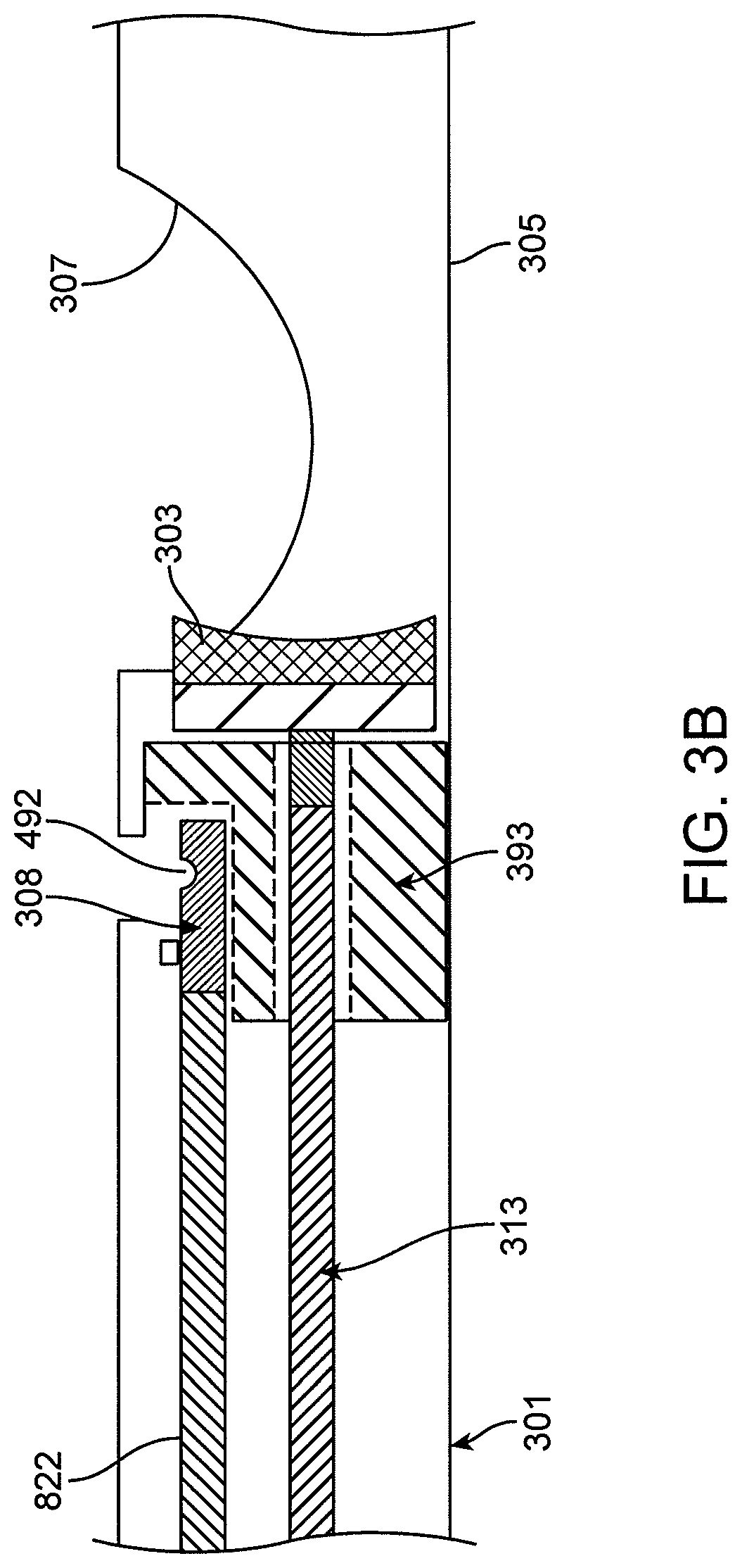
FIGS. 3A-3E show an atherectomy device having a drive shaft and a parallel imaging shaft extending alongside the drive shaft. The drive shaft and imaging shafts are separated from one another at the distal end and axially translatable relative to one another. FIG. 3A is an outer view of the device with the cutter in a proximal (cutting) position. FIG. 3B is a cross-section of the device of FIG. 3A. FIG. 3C is a cross-section through the outer shaft of the device of FIG. 3A. FIG. 3D shows the inflatable element of the device. FIG. 3E shows a close-up view of the imaging portion of the device.
FIGS. 4A-4B show a handle for use with the atherectomy device of FIGS. 3A-3E. FIG. 4A shows the breakout port of the handle for management of the drive shaft, imaging shaft, and balloon inflation lumen. FIG. 4B shows is a diagram of the handle components.
FIGS. 5A-5F show a knob configured to rotate the outer shaft of the catheter of FIGS. 3A-3E up to a set number of rotations without lengthening the device. FIG. 5A shows the inner portions of the knob. FIG. 5B show the inner portions of the knob with the spiral track in transparent. FIG. 5C shows the inner portions with a sleeve in transparent. FIG. 5D shows the inner portions and sleeve with an outer portion in transparent. FIG. 5E shows the inner portions with a slide in transparent that is in the proximal-most position. FIG. 5F shows the inner portions with a slide in transparent that is in the distal-most position.
FIGS. 6A-6B show a variation of an atherectomy catheter having an inflatable element configured to deflect the nosecone away from the catheter body at a hinge point to expose a cutter. FIG. 6A shows a variation of a distal end of an atherectomy catheter with the nosecone in a closed position. FIG. 6B shows a variation of a distal end of the atherectomy catheter with the nosecone in an open position. This embodiment includes a balloon mechanism configured to open the nosecone when the balloon is inflated.
FIGS. 6C-6D show an exemplary detailed view of the imaging element and the hinged activation closing mechanism of the catheter of FIGS. 6A-6B. FIG. 6C shows the activation mechanism in an open position. FIG. 6D shows the activation mechanism in a closed position.
FIG. 6E shows an exemplary detailed version of the atherectomy catheter of FIGS. 6A-6B including a balloon and sling element for deflecting the nosecone and exposing the cutter.
FIG. 7 shows an asymmetric cutting window.
FIGS. 8A-8B show a first embodiment of a handle configured such that the inner drive shaft can be extended axially at the distal end without requiring axial movement of the drive shaft at the proximal end. FIG. 8A shows the drive shaft in the compressed configuration. FIG. 8B shows the drive shaft in the extended configuration.
FIGS. 9A-9B shows a second embodiment of a handle configured such that the inner drive shaft can be extended axially at the distal end without requiring axial movement of the drive shaft at the proximal end. FIG. 9A shows the drive shaft in the compressed configuration.
FIG. 9B shows the drive shaft in the extended configuration.
FIG. 10 shows an exemplary optical alignment feature of a catheter handle for connection to a drive system.
FIG. 11 shows an exemplary optical connection feature of a handle that includes the optical alignment feature of FIG. 10.
FIG. 12 shows the optical connection of FIG. 11 in a compressed configuration.
FIGS. 13A-D shows an atherectomy device having a drive shaft and a coaxial imaging shaft extending within the drive shaft. The drive shaft and imaging shafts are separated from one another at the distal end and axially translatable relative to one another. FIG. 13A is an outer view of the device. FIG. 13B includes a transparent outer shaft and nosecone so as to show the drive shaft and imaging element therein. FIG. 13C shows the drive shaft and cutter in an extended (distal) packing position. FIG. 13D is a cross-section of the device.
FIG. 14 is an exemplary handle for use with the atherectomy device of FIGS. 13A-D.
DETAILED DESCRIPTION
Described herein are atherectomy catheters. In general, the atherectomy catheters can include a rotatable cutter connected to a drive shaft. Further, the atherectomy catheters can include on-board imaging, such as optical coherence tomography (OCT) imaging. The atherectomy catheters can include a distal housing (nosecone) configured to hold excised tissue. The drive shaft can be moved distally to pack the excised tissue into the nosecone.
In some embodiments, the atherectomy devices described herein can include an inflatable element configured to urge the cutter against the vessel wall. In some embodiments, the inflatable element can activate a hinge mechanism to hinge the nosecone off-axis with the catheter body, thereby exposing the cutter. In such embodiments, a biasing mechanism, such as a wedge, can optionally be used to realign the nosecone and the catheter body. In other embodiments, the inflatable element can urge the cutter against the vessel wall without a separate hinge mechanism. In such embodiments, the cutting window in the catheter can be sized so as to allow the tissue to invaginate within the cutting window and be excised by the rotatable cutter.
In some embodiments, the atherectomy devices described herein can be configured such that the imaging element and the cutter are driven by the same shaft. In other embodiments, there can be a separate imaging shaft and a separate drive shaft to separately control the distal rotation of the imaging element and the cutter, thereby advantageously reducing or eliminating nonuniform rotational distortion (NURD) in the resulting image. In such embodiments, the imaging and drive shafts can be driven by the same rotational mechanism at the proximal end. In such embodiments, the drive shaft and cutter can further advantageously be translated axially without requiring translation of the imaging shaft and imaging element.
Handles are also described herein for use with atherectomy devices. In some embodiments, the handle is configured to rotate an imaging shaft and a drive shaft concurrently while providing axial translation of only the drive shaft. In other embodiments, the handle is configured to provide axial movement of an optical fiber (with a drive shaft) at a distal end of the handle but not the proximal end of the handle.
FIGS. 1A-5F and 13A-14 show examples of atherectomy devices and handles having drive and imaging shafts that are separated from one another at the distal end and translatable relative to one another. FIGS. 1A-5F and 13A-14 also have cutters that are configured to be urged against the vessel wall with an inflatable element without using a separate hinge mechanism.
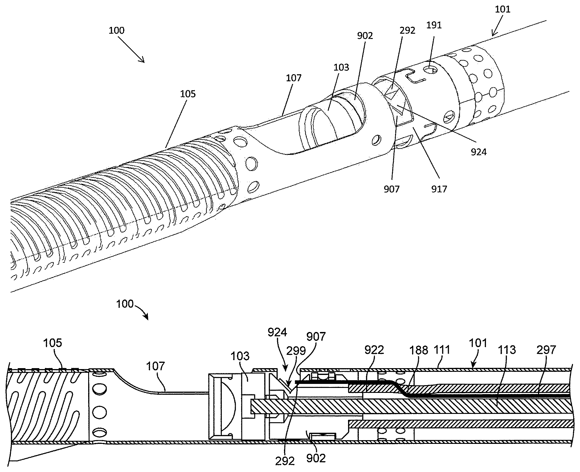
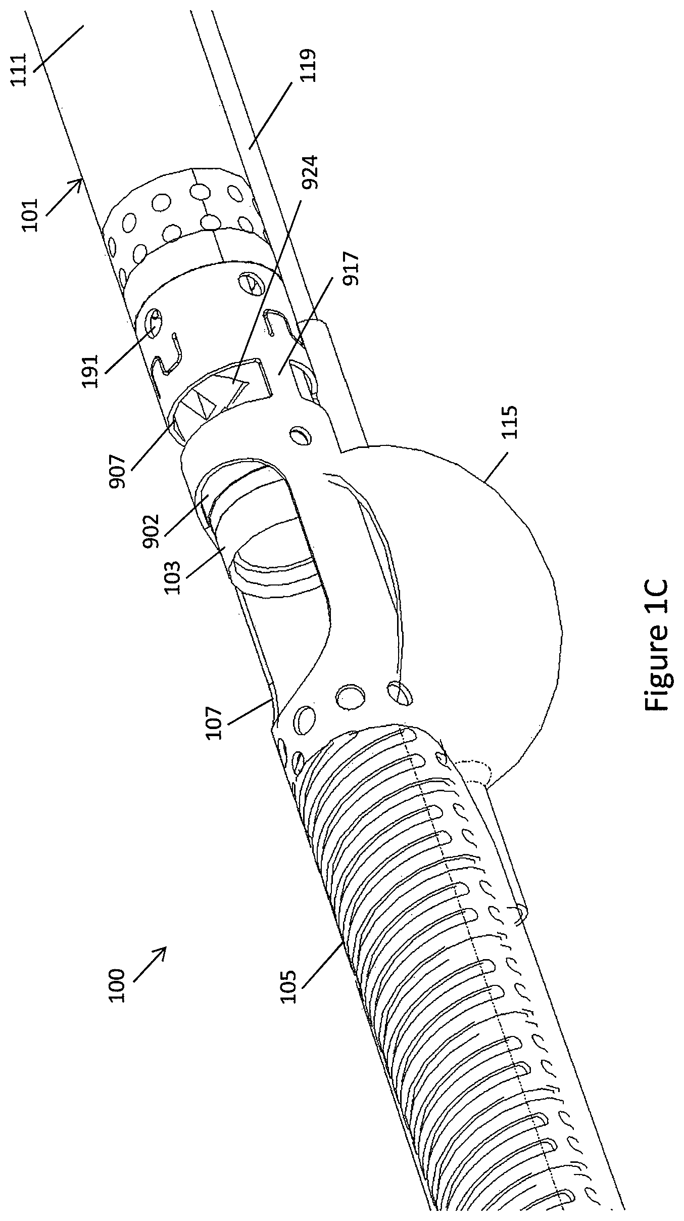
In one embodiment, referring to FIGS. 1A-1C, a catheter 100 can include a catheter body 101, a cutter 103 extending from the distal end of the catheter body 101, and an imaging collar 902 near the distal end of the catheter body 101 but proximal to the cutter 103. A nosecone 105 can extend from the distal end of the catheter body and around the cutter 103 to store tissue removed by the cutter 103. The nosecone 105 can include a cutting window 107 therein configured to expose a portion of the cutter 103. The catheter 100 can further include an inflatable element, such as a balloon 115 (see FIG. 1C), configured to urge the cutter 103 against the side of a vessel.
Referring to FIG. 1B, the catheter body 101 can include an outer shaft 111 and a drive shaft 113 extending inside the outer shaft 111. The outer shaft 111 can be configured to be turned, such as turned manually, to position the cutter 103 and/or the imaging collar 902 toward the desired location. The drive shaft 113 can extend through, and rotate relative to, the imaging collar 902. Further, the drive shaft 113 can be attached to the cutter 103 to rotate the cutter 103. Rotation of the cutter 103 can provide cutting due to the rotational motion of the sharp distal cutting edge. The drive shaft 113 can be rotated at up to 10,000 rpm, such as approximately 1,000 rpm to 5,000 rpm, e.g., 1,000 rpm, in a single direction, though rotation in both directions or at different speeds is possible.
Referring still to FIG. 1B, the catheter 100 can further include an optical fiber 297, the distal end of which can act as an imaging element 292 for OCT imaging. The imaging collar 902 can be attached to an imaging shaft 922 that extends within the catheter body 101 concentric with the drive shaft 113. As shown in FIG. 1B, the concentric imaging shaft 922 can extend between the drive shaft 113 and the outer shaft 111 (i.e. such that the drive shaft 113 is in the center). In other embodiments (such as described below with respect to FIGS. 13A-D), the drive shaft 113 can extend between the concentric imaging shaft 922 and the outer shaft 111 (i.e. such that the imaging shaft 922 is in the center). The rotation of the imaging shaft 922 and the drive shaft 113 can be decoupled from one another at the distal end of the device, thereby providing for separate rotation of the cutter 103 and the imaging element 292 (which can be the distal end of an optical fiber 297). As described below, in some embodiments, the rotation of the imaging shaft 922 and the drive shaft 113 can be coupled at the proximal end (such as in the handle so as to be driven by the same motor) while remaining decoupled along the length of the catheter.
The outer shaft 111 (or a housing connecting the outer shaft 111 to the nosecone 105) can include an imaging window 907 through which the imaging element 292 can be exposed. The imaging window 907 can extend 360 degrees around the circumference of the outer shaft 111, but can include structural struts 917 extending thereacross to both provide structural support and act as imaging markers. The imaging window 907 can further be used as a flush port to allow flush fluid to be delivered through the outer shaft 111 and to the area of imaging, thereby improving image quality. In some embodiments, flush fluid can extend through fluid ports 191 in the outer shaft 111.
The optical fiber 297 can run within the imaging shaft 922 to provide the imaging (e.g., OCT) signal. As shown in FIG. 1B, the optical fiber 297 can run between the inner diameter of the imaging shaft 922 and the outer diameter of the drive shaft 113 and can be free to flow therein. At distal point 188, the fiber 297 can cross to the outside of the imaging shaft 922 to attach to the imaging collar 902, such as in an opening 924 in the imaging collar 902. Leaving the optical fiber 297 free to float within the imaging shaft 922 for the majority of the length of the catheter body 101 ensures that the fiber is not compressed or stretched as the catheter 100 bends as it is advanced through tortuous anatomy. As described further below, the fiber 297 can be rotated with the imaging shaft at both the proximal and distal ends of the fiber 297. Accordingly, the fiber 297 does not have to wrap around the drive shaft 113 as it rotates, advantageously both reducing the likelihood of fiber breakage and allowing the imaging element and cutter to rotate in a single direction.
As shown in FIG. 1B, a reflective element 299, such as a mirror, a polished pin, a film deposited on the surface of the imaging collar 902, or a polished surface of the imaging collar 902 itself, can further be located within the opening 924 in the imaging collar 902 to radially direct light from the optical fiber 297 into the tissue. The reflective element 299 can sit, for example, at a 35 degree to 55 degree angle, such as a 45 degree angle, relative to the central axis of the optical fiber 297 so as to direct the light sideways into the tissue. The distal end of the optical fiber 297 can be located less than 3 mm from the distal edge of the cutter 103, such as less than 1.5 mm from the cutting edge, such as less than or equal to 1.2 mm, such as less than or equal to 1 mm. By having the imaging element 292 close to the cutting edge, the resulting image can advantageously correlate with and depict the portions of the vessel being cut.
As shown in FIG. 1C, an inflatable element, such as a balloon 115, can be located opposite to the cutting window 107. Referring to FIG. 1C, the balloon 115 can be attached to an inflation tube 119, which can alongside or be embedded in the outer shaft 111. The balloon 115 can be attached at the distal end to the outer shaft 111 (at a location just proximal to the imaging window 907) and at the proximal end to the inflation tube 119 inside the outer shaft 111, such as through a hole in the outer shaft 111. In some embodiments, the inflation tube 119 can radially align with one or more of the struts 917 so as to not hinder the resulting image. Inflation of the balloon can position or urge the cutting window 107 and thus the cutter against the tissue. Further, the cutting window can be sized and dimensioned such that inflation of the balloon 115 causes the tissue to invaginate within the cutting window, thereby improving the cutting quality of the device. Further, the cutting window can be sized such that it is smaller than the diameter of the cutter, thereby preventing the cutter from popping out as the cutting window and cutter are urged against the vessel wall. In one embodiment, the window 107 can extend between 90 and 270 degrees around the circumference of the nosecone or catheter, such as 150 to 210 degrees, such as between 175 and 180 degrees. Having a window 107 of these dimensions, such as that extends 175 and 180 degrees around the circumference of the nosecone or catheter, can advantageously provide significant tissue capture upon inflation of the balloon 115 while still providing adequate stiffness to the nosecone or catheter.
The catheter 100 can further include a mechanism for packing tissue into the nosecone 105, such as by moving the drive shaft 113 and cutter 103 axially such that tissue can be urged by the distal surface of the cutter 103. Advantageously, the drive shaft 113 can be moved axially without movement of the imaging shaft 922, thereby allowing for packing of the tissue without disrupting the imaging.
Advantageously, by having an imaging shaft that is separate or decoupled from the drive shaft at their respective distal ends, the rotation of the cutter and the optical fiber can be mechanically isolated from one another (i.e., such that a mechanical action or reaction of one does not affect the other). For example, if the cutter stalls during rotation, such as when it hits a hard piece of tissue, the mechanically isolated imaging element can remain unaffected and continue rotating at the same constant speed. Such continuous rotation of the imaging element reduces or eliminates rotational distortion, such as nonuniform rotational distortion (NURD), thereby improving imaging quality.
Further, by having separate imaging and drive shafts, the drive shaft can advantageously be used to pack tissue while maintaining the imaging element in the same location, thereby ensuring that the imaging location is constant and well known. Moreover, by having separate imaging and drive shafts, the fluid flush can be delivered close to the imaging element even when the drive shaft is moved distally to pack tissue.
Further, by using the balloon 115 of catheter 100 to urge the cutter against the vessel wall and by having an optimally designed cutting window, tissue can be pressed into the cutting window and cut, thereby improving cutting quality without requiring an articulation mechanism in the catheter. Further, the balloon 115 can advantageously act as an occlusion element to restrict blood flow to the imaging element 292, thereby reducing the amount of saline flush required to obtain a clear image and improving image quality.
As noted above, in some embodiments, the drive shaft 113 and imaging shaft 922 can be unconnected at the distal end of the catheter to allow for separate imaging and cutting but connected at the proximal end of the catheter so that they can be rotated from the same source, such as the same drive system. Although the shafts can be connected at the proximal end of the cutter, rotational distortion can still be avoided because the rotating motor can be strong enough to spin at the same speed regardless of the resistance to rotation placed on the cutter at the distal end. Accordingly, even if the drive shaft slows down due to stalling, the imaging shaft can continue to rotate at the same constant input speed.
Referring to FIGS. 2A-2D, the catheter 100 can be used with a handle 200 configured such that the drive shaft 113 and the imaging shaft 922 can be rotated separately at the distal end of the catheter while being rotated with the same source at the proximal end of the catheter. Rotation with the same source can advantageously requires only one motor (reducing the size and complexity of the device), allows for the fiber to stay on the centerline of the catheter and handle, and can provide the same relative speed for zero relative speed between the imaging and drive shafts in aid in preserving imaging fiber integrity. As described further below, the handle 200 can further include a mechanism that allows for axial translation of the drive shaft 113 (e.g., to pack tissue with the cutter), but maintains the fixed position of the imaging shaft 922. Further, the handle 200 can be configured to as to allow free rotation of the fiber 297 therein such that minimal or no fiber management and/or wrapping of the fiber is necessary.
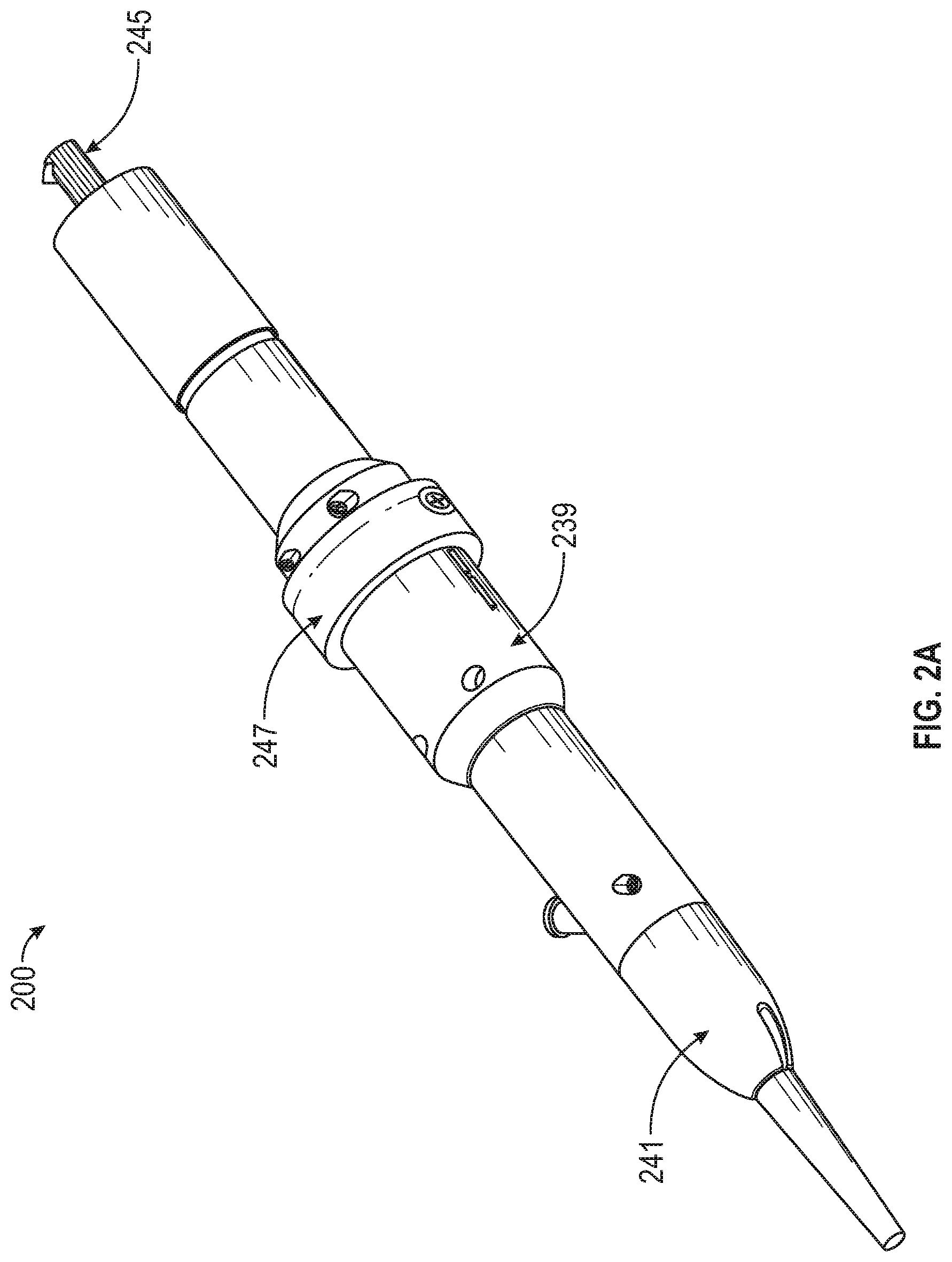
Referring to FIG. 2A, the handle 200 can include an outer shell 239, a handle tip 241 configured to connect to the outer shaft 111 of the catheter 100, and an optical connector 245 configured to engage with a drive system and light source. The handle 200 can further include a handle ring 247 configured to slide along the handle 200 to translate the drive shaft 113 axially. The handle tip 241 can be configured to rotate relative to the rest of the handle 200 to allow the user to torque the outer shaft 111 to orient the distal tip of the catheter 100 in the desired position.
Referring to FIG. 2B, the proximal end of the catheter outer shaft 111 can be connected to a rotation mechanism 251 at the distal end of the catheter. The proximal end of the imaging shaft 922 can be connected to an imaging shaft hypotube 253 attached to an imaging shaft coupler 255. The proximal end of the drive shaft 113 can be attached to a drive shaft hypotube 257 that is attached to a drive shaft coupler 259. The hypotubes can telescope with respect to one another, thereby allowing for translation of the drive shaft within the imaging shaft, and can be configured to transmit torque and provide a fluid seal.
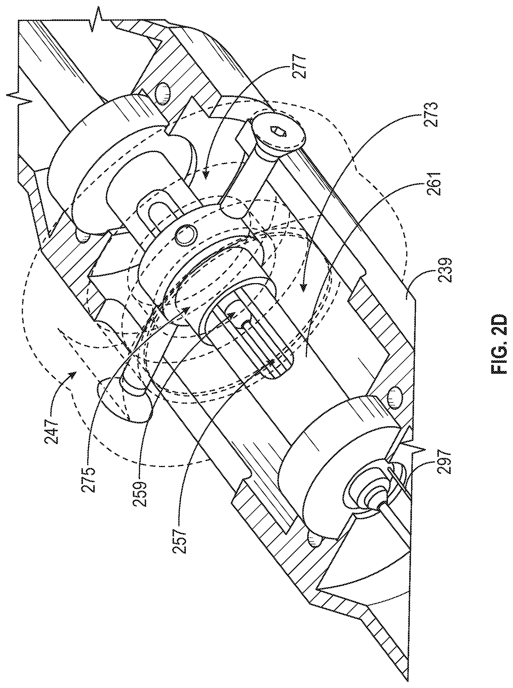
Referring to FIGS. 2B-2D, the imaging shaft coupler 255 can be attached to a drive bridge 261, which is in turn rotationally attached to the drive shaft coupler 259 (which extends within and concentric with the drive shaft bridge 261) through a pin 271. The drive bridge 261 is then attached to the proximal optical subassembly, which is configured to impart rotation thereto (thereby causing rotating of both the drive shaft 113 and the imaging shaft 922), such as via a drive system.
Referring to FIG. 2D, a bearing 273 extends within the handle 200. The bearing 273 engages, with its inner race, a drivebridge coupler 275 that is connected to the drive bridge 261. This connection allows the drivebridge coupler 275 (and drivebridge 261) to rotate within the bearing 273. The bearing 273 further engages, with its outer race, a handle ring coupler 277 connected to the handle ring 247 where the outer race of the bearing 273, the handle ring coupler 277, and the handle ring 247 do not rotate relative to the handle 200. This engagement allows the bearing, and thus the drive bridge coupler, the drive shaft coupler, and the drive shaft hypotube to rotate relative to the handle 200. Moreover, the engagement still allows the drive bridge coupler, the drive shaft coupler, and the drive shaft hypotube to translate proximally or distally when the handle ring is 247 is translated proximally or distally as desired by the user.
As shown in FIGS. 2B and 2D, the optical fiber 297 can be configured to extend out of the imaging shaft hypotube 253 at a point 283 just distal to the drive bridge 261. The optical fiber 297 can then traverse along the outer surface of the drive bridge 261, such as within a groove in the drive bridge 261, until it reaches the proximal optical assembly 263, where it can connect to light source. Accordingly, while the drive shaft coupler 259 and drive bridge 261, and thus the drive shaft 113, can move proximally and distally, the optical fiber 297 can remain at a fixed axial position. Having the axial fiber in a fixed axial position advantageously avoids requiring additional length of fiber 297 and/or placing unnecessary tension on the fiber 297. Further, by having the optical fiber 297 traverse along a groove in the outer surface of the drive bridge, the fiber 297 can rotate with the drive bridge 261. Rotating of the fiber with the drive bridge 261 ensures that the fiber maintains a clear path as it is rotated, i.e., such that it is not required to wrap around anything within the handle. Thus, as the imaging connection subassembly 263 is rotated by the drive system, the torque can be transmitted simultaneously through the imaging shaft 922, optical fiber 297, and drive shaft 113.
Handle 200 advantageously provides for rotation of the concentric imaging and drive shafts while allowing for axial movement of the drive shaft and not the imaging shaft or imaging fiber. The handle 200 can further advantageously be configured such that the optical fiber does not have to undergo any steep bends therein, thereby making the fiber more robust.
In some embodiments, rotation of the drive shaft and imaging shaft can be decoupled by, for example, using magnets in the handle to couple the input rotation with the drive shaft rotation. In such a configuration, the internal drive shaft can be rotated at a speed different than the imaging shaft without interrupting the rotation of the optical fiber. Rotating the imaging shaft at a different speed, or without, the drive shaft can advantageously allow for imaging with cutting and/or rotating at different speeds that are individually optimized for imaging and cutting.
Although described as being used with catheter 100, it is to be understood that the handle 200 and/or elements of the handle could be used with a variety of different catheters while still providing separate rotation of concentric imaging and drive shafts and/or axial movement of one or more shafts without axial movement of another.
FIGS. 13A-D show another example of an atherectomy catheter 1300 having drive and imaging shafts that are separated at the distal end and axially translatable relative to one another. The catheter 1300 is also configured to be urged against the vessel wall without a separate hinge mechanism. The catheter 1300 can include a catheter body 1301, a drive shaft 1313 extending inside an outer shaft 1311, and an imaging shaft 1322 extending through the drive shaft 1313 (e.g., such that the imaging shaft 1322 extends through the center of the device). The drive shaft can include a clear annular portion 1395 on the distal end thereof.
Referring to FIG. 13D, an optical fiber 1397 can extend through the center of the imaging shaft 1322 (and thus through the center of the catheter 1300) to provide the imaging (e.g., OCT) signal. The optical fiber 1397 can be attached at the distal end of the imaging shaft 1322 (such as in the bulb 1387, described below) but can be otherwise free to float within the imaging shaft 1322. The cutting window 1307 can also act as an imaging window through which the imaging element 1392 can be exposed. Similar to catheter 100, the window 1307 can include a structural struts 1319 therethrough to provide structure support and to act as imaging markers.
Referring still to FIG. 13D, the imaging shaft 1322 can end in a bulb 1387, which can be made, for example, of stainless steel. The bulb 1387 can have a window therein through which light from the optical fiber can be transmitted. The bulb 1387 can further include a glue in which the distal end of the optical fiber 297 us embedded. Further, in some embodiments, the bulb 1387 can house a reflective element 1399, which can be situated at an angle (such as 40-60 degrees, e.g., 45 degrees) relative to the fiber so as to direct light from the optical fiber out through the clear annular portion 1395. Light can thus travel through the optical fiber 1397, bounce off of the reflective element 1399, extend through the clear annular portion 1395, through the imaging window 1377, and into the tissue.
As noted above, the drive shaft 1313 can include a clear annular portion 1395 at the distal end thereof. The clear annular portion 1395 can advantageously keep blood away from the exit path of the OCT light beam while providing a window for the light beam to travel through. The clear annular portion 1395 can include an optically transparent material, such as sapphire, polycarbonate, glass, or acrylic. In some embodiments, material used for the clear annular portion 1395 can be substantially free of micro-defects that can cause light therein to scatter, as such scattering of light can reduce the amount of light transmitted to and from the tissue and reduce image quality. In some embodiments, the materials used for the clear annular portion 1395 can have a flat response between 1260 nm and 1380 nm, i.e., the optical transmission can be relative constant between the used wavelength. Having a flat response advantageously ensures that there is no interference with OCT signals, improving image quality.
In some embodiments, the refractive index of the clear annular portion 1395 can be similar to the refractive index of the glue in which the distal end of the optical fiber is embedded. For example, the refractive index of polycarbonate is low, such as between 1.584 and 1.586, which in some embodiments can be comparable to the refractive index of the glue attached to the fiber, such as Masterbond EP42HT-2, EpoTek OG127-4 or OG116, produced by Epoxy Technology and UV curable photonics adhesive OP-4-20658. Using a clear annular portion 1395 having a refractive index that is similar to the glue in which the distal end of the optical fiber is embedded advantageously reduces the back-reflection at the glue/annular portion interface, thereby increasing image quality. As another example, the refractive index of sapphire is high, such as about 1.78, which can result in a higher back-reflection of a glue with a low refractive index (such as those described above) is used (a higher mismatch between the refractive indices results in higher back-reflection). Accordingly, a glue with a higher mismatch can be used, such as NOA 1625 from Norland Optical adhesives.
In other embodiments, rather than matching the refractive indices of the glue and the clear annular portion 1395, the housing geometry could be modified such that the light beam hits the clear annular portion 1395 at an angle so that very little or none of the reflective light can be coupled back into the fiber. In other words, the mirror, glue, fiber, the clear optical portion can be configured such that the angle of incidence of light to the interface medium between the glue and the clear annular portion is close to the polarization angle (also called the Brewster's angle) wherein all of the light is transmitted with minimal reflection.
When the clear annular portion 1395 is used, the focal length of the OCT light beam can be extended to compensate for the additional material through which the light has to travel. To do so, the beam diameter at the waste can be increased or a fiber or GRIN fiber with a larger diameter can be used.
A cutter 1303, such as an annular cutter, can be attached to the clear annular portion 1395 of the drive shaft 1313. In some embodiments, the cutter can be carved out of the clear annular portion 1395. For example, if the material for the clear annular portion 1395 is strong, such as sapphire, then the cutter 1303 and clear annular portion 1395 can be made of the same piece. Having the cutter 1303 and clear annular portion 1395 be made of the same piece can advantageously allow the images to be generated from a location very close to the cutter 1303, helping to achieve more precise cutting.
Further, similar to the catheter 100, the catheter 1300 can include a nosecone 1305 extending from the distal end of the catheter body around the cutter 1303 to store tissue removed by the cutter 1303. The nosecone 1305 includes a cutting window 1307 therein configured to expose a portion of the cutter 1303. Similar to catheter 100, the catheter 1300 can further includes an inflatable element, such as a balloon, configured to urge the cutter 1303 against the side of a vessel (and can include a corresponding optimized cutting window 1307 for cutting tissue as described with respect to catheter 100).
The rotation of the imaging shaft 1322 and the drive shaft 1313 can be decoupled from one another at the distal end of the device, thereby providing for separate rotation of the cutter 1303 and the imaging element 1392. As described below, in some embodiments, the rotation of the imaging shaft 1322 and the drive shaft 1313 can be coupled at the proximal end (such as in the handle so as to be driven by the same motor) while remaining decoupled along the length of the catheter. In some embodiments, a separating layer 1384, such as a polyimide layer, can be placed between the drive shaft 1313 and the imaging shaft 1322. The separating layer 1374 can advantageously be used to prevent the transfer of energy between the drive shaft 1313 and the imaging shaft 1322 (for example, such that if the drive shaft 1313 gets bogged down while cutting, the chances of it affecting the imaging shaft 1322 will be reduced).
The catheter 1300 can include a mechanism for packing tissue into the nosecone 1305, such as by moving the drive shaft 1313 and cutter 1303 distally as shown in FIG. 13C. Advantageously, the drive shaft 113 can be moved axially without movement of the imaging shaft 122, thereby allowing for packing of the tissue without disrupting the imaging.
Similar to catheter 100, by having an imaging shaft that is separate or decoupled from the drive shaft at their respective distal ends, the rotation of the cutter and the optical fiber can be mechanically isolated from one another, imaging quality can be improved due to reduced NURD.
Further, by having separate imaging and drive shafts, the drive shaft can advantageously be used to pack tissue while maintaining the imaging element in the same location, thereby ensuring that the imaging location is constant and well known.
By placing the imaging element within the center of the catheter, the catheter can advantageously be reduced in size (for example, relative to a device where there is an annular space between an inner drive shaft and an outer imaging shaft). The catheter 1300 can thus be, for example, less than 8 French, such as 6-8 French, which can advantageously make the catheter 1300 useable in small diameter vessels, such as coronary vessels. Further, by placing the drive shaft around the imaging shaft, as in catheter 1300, the drive shaft can advantageously be larger and more robust, such as 0.05'' to 0.06.'' In some embodiments, the drive shaft can include a multi-layer coil, which can also advantageously increase the robustness of the drive shaft, thereby providing a cutting system that is more resistant to stalling.
In some embodiments, the drive shaft 1313 and imaging shaft 1322 can be unconnected at the distal end of the catheter to allow for separate imaging and cutting but connected at the proximal end of the catheter so that they can be rotated from the same source, such as the same drive system. Although the shafts can be connected at the proximal end of the cutter, rotational distortion can still be avoided because the rotating motor can be strong enough to spin at the same speed regardless of the torque placed on the cutter at the distal end. Accordingly, even if the drive shaft slows down due to stalling, the imaging shaft can continue to rotate at the same constant speed.
Referring to FIG. 14, the catheter 1300 can be used with a handle 1400 configured such that the drive shaft 1313 and the imaging shaft 1322 can be rotated separately at the distal end of the catheter while being rotated with the same source at the proximal end of the catheter. The handle 1400 can be configured similar to the handle 400 of FIGS. 4A-4B, described further below.
FIGS. 3A-E show another example of an atherectomy catheter 300 having drive and imaging shafts that are separated at the distal end and axially translatable relative to one another. The catheter 300 is also configured to be urged against the vessel wall without a separate hinge mechanism. The catheter 300 can include a catheter body 301, a cutter 303 extending from the distal end of the catheter body 301, and an imaging tip 308 near the distal end of the catheter body 301 but proximal to the cutter 303. A nosecone 305 can extend from the distal end of the catheter body and around the cutter 303 to store tissue removed by the cutter 303. The nosecone 305 can include a cutting window 307 therein configured to expose a portion of the cutter 303. The catheter 300 can further include an inflatable element, such as a balloon 315 (see FIG. 3D), configured to urge the cutter 303 against the side of a vessel.
Referring to FIGS. 3A-3C, the catheter body 301 can include an outer shaft 311 and a drive shaft 313 extending inside the outer shaft 311. The outer shaft 311 can be configured to be turned, such as turned manually, to position the cutter 303 and/or the imaging tip 308 toward the desired location. The drive shaft 313 can be attached to the cutter 303 to rotate the cutter 303. Rotation of the cutter 303 can provide cutting due to the rotational motion of the sharp distal cutting edge. The drive shaft 313 can be rotated at up to 10,000 rpm, such as 1,000 to 5,000 rpm, e.g., 1,000 rpm, though rotation in both directions or at different speeds is possible. The drive shaft 313 can be held on-center at the distal tip of the device using a bushing 393 (within which the drive shaft 313 can rotate).
Referring still to FIGS. 3A-3C, the catheter 300 can further include an imaging element 492, such as an OCT imaging element. The imaging element 492 can include an optical fiber 497. The imaging tip 308 can be attached to an imaging shaft 822 that extends within the catheter body 301 next to or parallel with the drive shaft 313. The imaging shaft 322 can be off-center at the distal tip of the device and be parallel to the drive shaft 313, as shown in FIG. 3B. The imaging shaft 322 can be held in place by the bushing 393.
The rotation of the imaging shaft 822 and the drive shaft 313 can be decoupled at the distal end of the device, thereby providing for mechanically isolated rotation of the cutter 303 and the imaging element 492. As described below, in some embodiments, the rotation of the imaging shaft 822 and the drive shaft 313 can be coupled at the proximal end (such as in the handle so as to be driven by the same motor) while remaining decoupled along the length of the catheter. Optionally, as shown in FIG. 3C, the imaging shaft 822 and/or the drive shaft 313 can include a stationary sheath 391a,b therearound to provide protection and support.
The outer shaft 311 can include an imaging window 807 through which the imaging element 492 can be exposed. The imaging window 807 can have a width of less than 1 mm while still enabling OCT imaging therethrough. The imaging window 807 can extend 360 degrees around the circumference of the outer shaft 311, but can include structural struts 317 extending thereacross to both provide structural support and act as imaging markers. In some embodiments, the struts 317 can be offset to account for the off-center imaging tip 308, enabling accurate OCT image orientation.
The imaging window 807 can further be used as a flush port to allow flush fluid to be delivered through the imaging shaft 822 and to the area of imaging, thereby improving image quality. Advantageously, by having the fluid pumped directly through the imaging shaft, the dimensions of the imaging window 807 do not need to be extended to enable this type of flushing.
The optical fiber 497 can run through the imaging shaft 822 to provide the imaging (e.g., OCT) signal. The optical fiber 497 can be attached at its distal end to the imaging tip 308. The optical fiber 497 can otherwise be free to float within the imaging shaft 822. As shown in FIG. 3E, a reflective element 499, such as a mirror, polished pin, a film deposited on the surface of the tip 308, or polished surface of the tip 308 itself, can further be located on the imaging tip 308 to radially direct light from the optical fiber 497 into the tissue. The reflective element 499 can be at an angle, such as 35 to 55 degrees, such as 45 degrees, relative to the central axis of the fiber 497 to reflect light into the tissue. The distal end of the optical fiber 497 can be located less than 3 mm from the distal edge of the cutter 303, such as less than 2.0 mm from the cutting edge, such as less than or equal to 1.5 mm, such as less than or equal to 1 mm. By having the imaging element 492 close to the cutting edge, the resulting image can advantageously align with the portions of the vessel being cut.
As shown in FIG. 3D, an inflatable element, such as a balloon 315, can be located opposite to the cutting window 307. The balloon 315 can be attached to an inflation tube 319 (see FIG. 3C), which can run inside the outer shaft 311. Thus, the balloon 315 can be attached at the distal end to the outer shaft 311 (just proximal to the imaging window 807) and at the proximal end to the inflation tube 319 inside the outer shaft 311, such as through a hole 388 in the outer shaft 311. Inflation of the balloon 315 can urge the cutting window 307 and thus the cutter 303 against the tissue. Further, the cutting window 307 and the balloon can be sized and dimensioned such that inflation of the ba
D00000
D00001
D00002
D00003
D00004
D00005
D00006
D00007
D00008
D00009
D00010
D00011
D00012
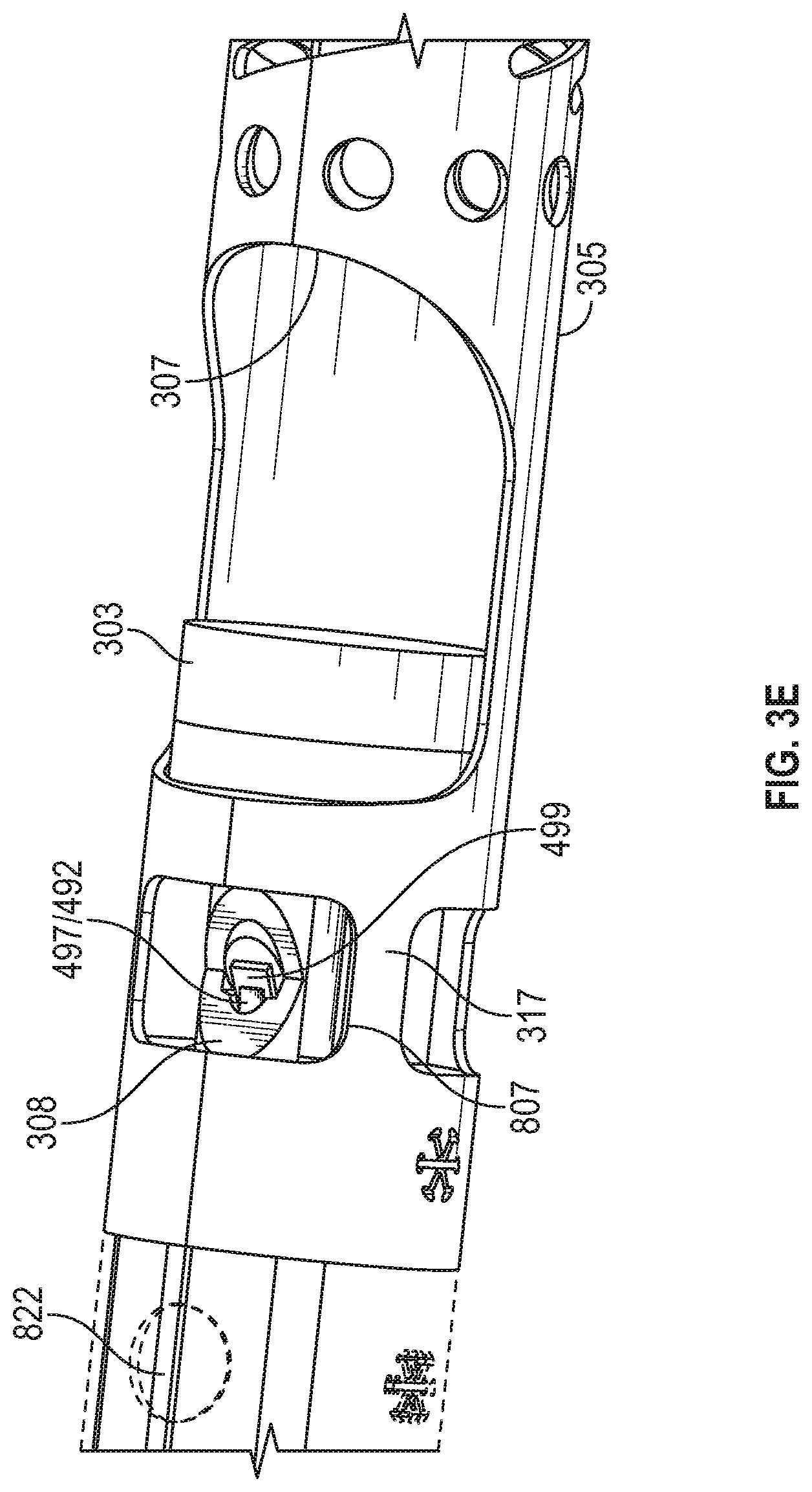
D00013

D00014

D00015
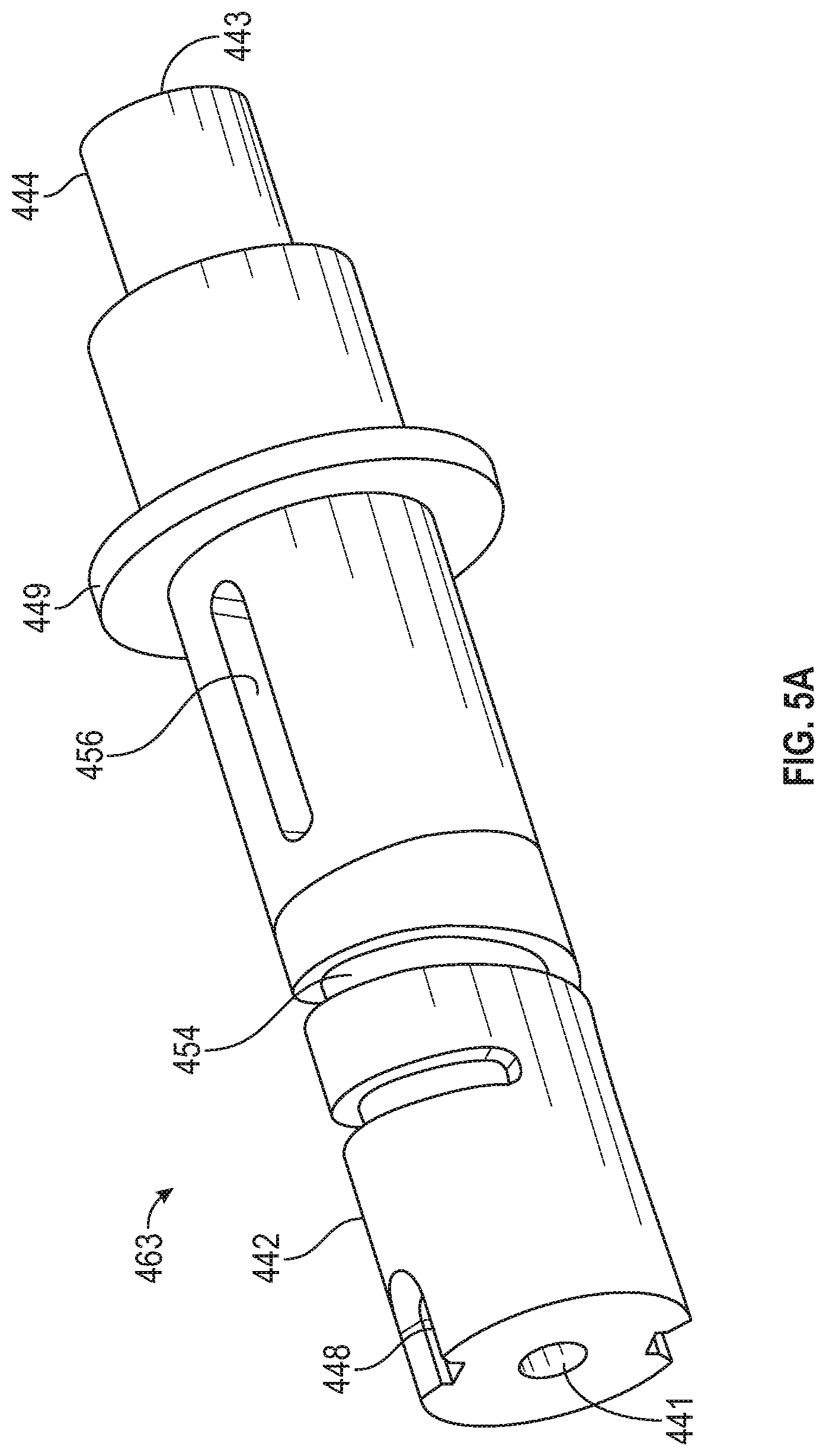
D00016

D00017

D00018

D00019

D00020

D00021
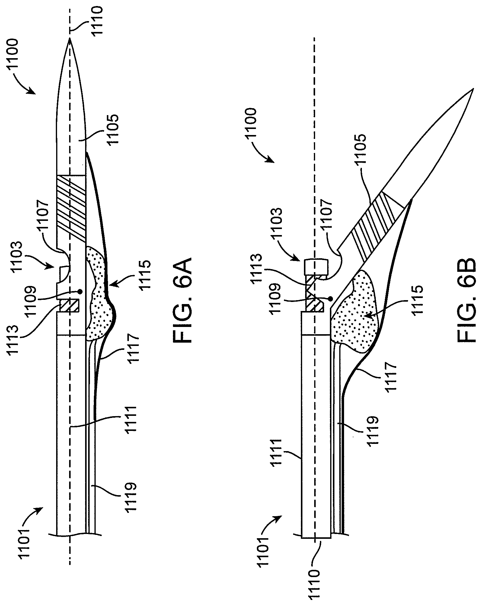
D00022
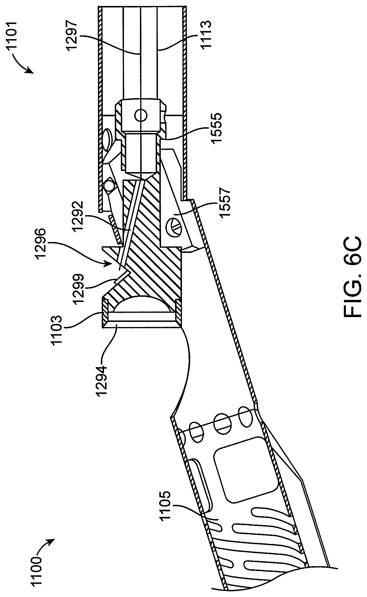
D00023

D00024

D00025

D00026
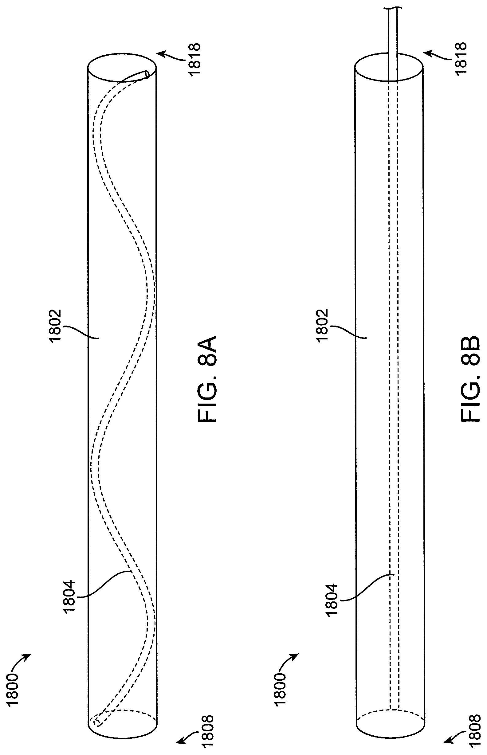
D00027
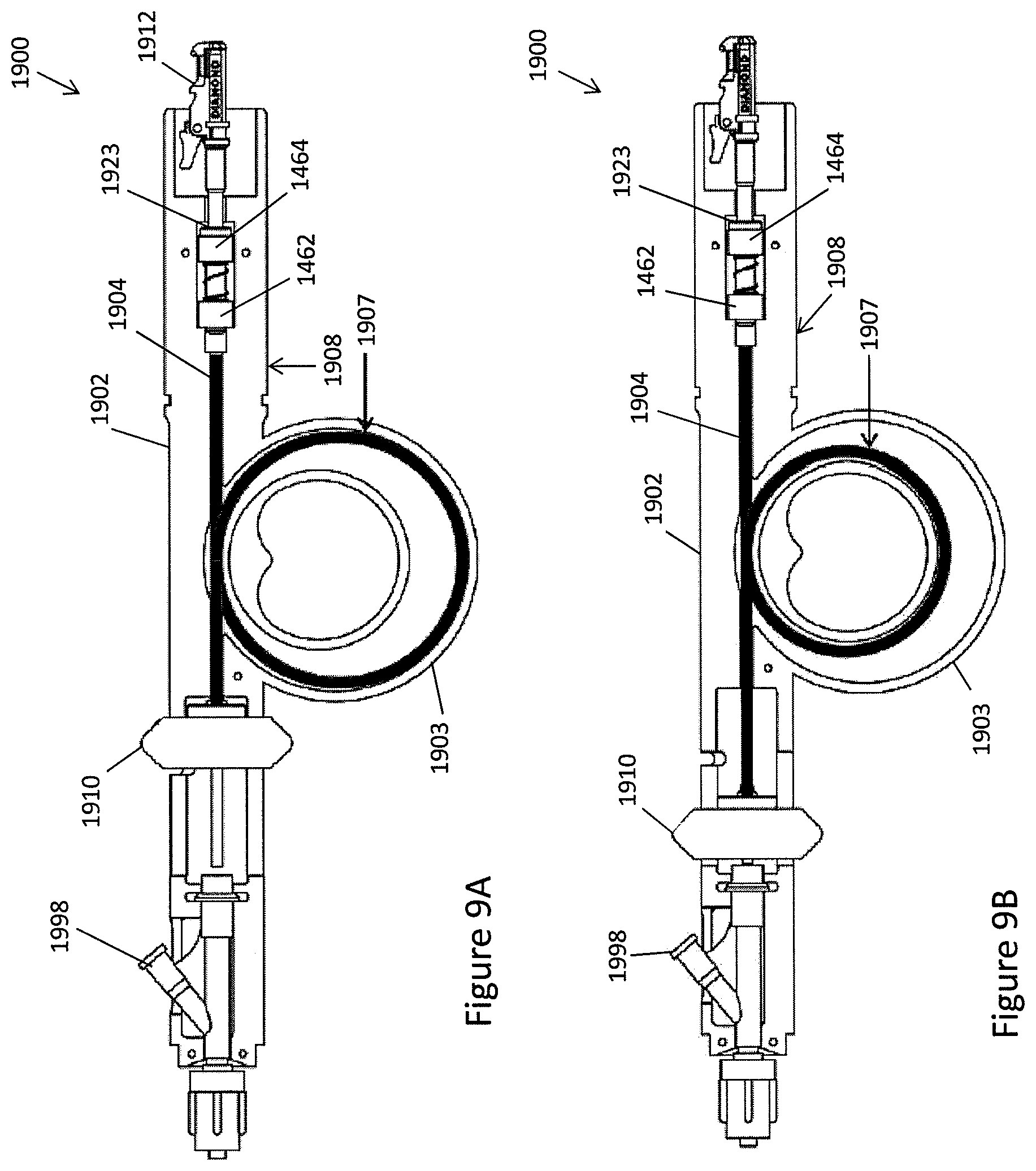
D00028

D00029

D00030

D00031

D00032
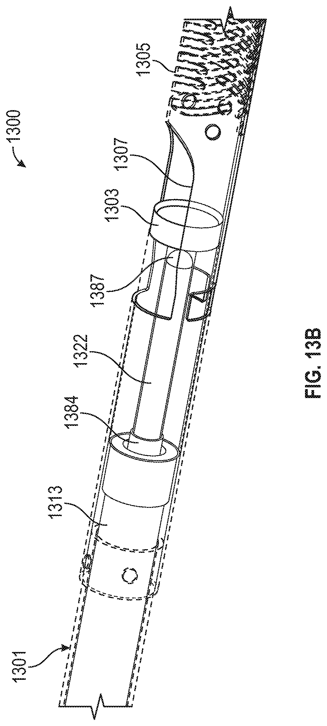
D00033
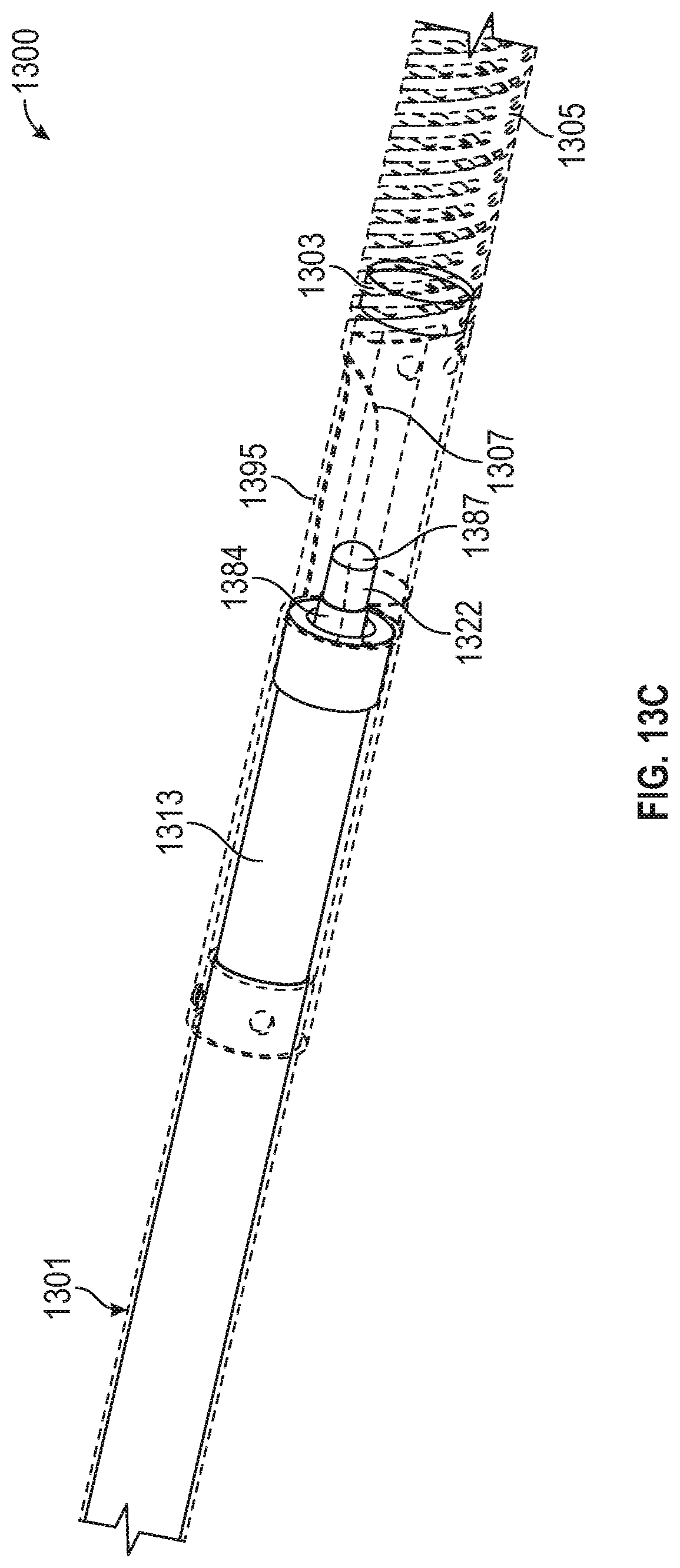
D00034

D00035

XML
uspto.report is an independent third-party trademark research tool that is not affiliated, endorsed, or sponsored by the United States Patent and Trademark Office (USPTO) or any other governmental organization. The information provided by uspto.report is based on publicly available data at the time of writing and is intended for informational purposes only.
While we strive to provide accurate and up-to-date information, we do not guarantee the accuracy, completeness, reliability, or suitability of the information displayed on this site. The use of this site is at your own risk. Any reliance you place on such information is therefore strictly at your own risk.
All official trademark data, including owner information, should be verified by visiting the official USPTO website at www.uspto.gov. This site is not intended to replace professional legal advice and should not be used as a substitute for consulting with a legal professional who is knowledgeable about trademark law.