Glenoid implant surgery using patient specific instrumentation
Couture , et al. Ja
U.S. patent number 10,543,100 [Application Number 14/386,620] was granted by the patent office on 2020-01-28 for glenoid implant surgery using patient specific instrumentation. This patent grant is currently assigned to ZIMMER, INC.. The grantee listed for this patent is ORTHOSOFT, INC.. Invention is credited to Jean-Guillaume Abiven, Pierre Couture, Thomas Gourgon, Jean-Sebastien Merette, Alain Richard.


View All Diagrams
| United States Patent | 10,543,100 |
| Couture , et al. | January 28, 2020 |
Glenoid implant surgery using patient specific instrumentation
Abstract
A pin placement instrument for placing a pin in a bone comprises an anatomical interface with a hook-like portion being opened in a lateral direction of the instrument to receive a bone therein in a planned position. A drill guide is connected to the anatomical interface and defining at least one guide slot in a longitudinal direction of the instrument. The guide slot has a lateral opening over its full length in the drill guide to allow lateral withdrawal of the instrument in said lateral direction with the pin placed in the bone passing through the lateral opening. A bushing is removably placed in said guide slot via said longitudinal direction in a planned fit, the bushing defining a throughbore aligned with the guide slot and adapted to receive the pin extending in said longitudinal direction when the bushing is in the guide slot for pin placement.
| Inventors: | Couture; Pierre (Montreal, CA), Merette; Jean-Sebastien (Montreal, CA), Richard; Alain (Lachine, CA), Abiven; Jean-Guillaume (Montreal, CA), Gourgon; Thomas (Montreal, CA) | ||||||||||
|---|---|---|---|---|---|---|---|---|---|---|---|
| Applicant: |
|
||||||||||
| Assignee: | ZIMMER, INC. (Warsaw,
IN) |
||||||||||
| Family ID: | 49258018 | ||||||||||
| Appl. No.: | 14/386,620 | ||||||||||
| Filed: | March 28, 2013 | ||||||||||
| PCT Filed: | March 28, 2013 | ||||||||||
| PCT No.: | PCT/CA2013/050253 | ||||||||||
| 371(c)(1),(2),(4) Date: | September 19, 2014 | ||||||||||
| PCT Pub. No.: | WO2013/142998 | ||||||||||
| PCT Pub. Date: | October 03, 2013 |
Prior Publication Data
| Document Identifier | Publication Date | |
|---|---|---|
| US 20150073424 A1 | Mar 12, 2015 | |
Related U.S. Patent Documents
| Application Number | Filing Date | Patent Number | Issue Date | ||
|---|---|---|---|---|---|
| 61616623 | Mar 28, 2012 | ||||
| 61659272 | Jun 13, 2012 | ||||
| 61675955 | Jul 26, 2012 | ||||
| Current U.S. Class: | 1/1 |
| Current CPC Class: | A61B 17/1684 (20130101); A61B 17/1778 (20161101); A61F 2/4081 (20130101); A61F 2002/4085 (20130101); A61F 2002/30736 (20130101); A61B 2017/568 (20130101) |
| Current International Class: | A61B 17/17 (20060101); A61F 2/40 (20060101); A61B 17/16 (20060101); A61F 2/30 (20060101); A61B 17/56 (20060101) |
| Field of Search: | ;606/96-98 |
References Cited [Referenced By]
U.S. Patent Documents
| 4841975 | June 1989 | Woolson |
| 5030219 | July 1991 | Matsen, III et al. |
| 5098383 | March 1992 | Hemmy et al. |
| 5354300 | October 1994 | Goble et al. |
| 5490854 | February 1996 | Fisher et al. |
| 5768134 | June 1998 | Swaelens et al. |
| 5769856 | June 1998 | Dong |
| 5871018 | February 1999 | Delp et al. |
| 5916219 | June 1999 | Matsuno et al. |
| 6379386 | April 2002 | Resch et al. |
| 6428541 | August 2002 | Boyd et al. |
| 7357057 | April 2008 | Chiang |
| 7468075 | December 2008 | Lang et al. |
| 7510557 | March 2009 | Bonutti |
| 7534263 | May 2009 | Burdulis |
| 7618451 | November 2009 | Berez et al. |
| 7634119 | December 2009 | Tsougarakis et al. |
| 7717956 | May 2010 | Lang |
| 7796791 | September 2010 | Tsougarakis et al. |
| 7799077 | September 2010 | Lang et al. |
| 7806896 | October 2010 | Bonutti |
| 7806897 | October 2010 | Bonutti |
| 7967868 | June 2011 | White et al. |
| 7981158 | July 2011 | Fitz et al. |
| 8062302 | November 2011 | Lang et al. |
| 8066708 | November 2011 | Lang et al. |
| 8070752 | December 2011 | Metzger et al. |
| 8077950 | December 2011 | Tsougarakis et al. |
| 8083745 | December 2011 | Lang et al. |
| 8092465 | January 2012 | Metzger et al. |
| 8094900 | January 2012 | Steines et al. |
| 8105330 | January 2012 | Fitz et al. |
| 8122582 | February 2012 | Burdulis, Jr. et al. |
| 8133234 | March 2012 | Meridew et al. |
| 8160345 | April 2012 | Pavlovskaia et al. |
| 8175683 | May 2012 | Roose |
| 8221430 | July 2012 | Park et al. |
| 8234097 | July 2012 | Steines et al. |
| 8241293 | August 2012 | Stone et al. |
| 8282646 | October 2012 | Schoenefeld et al. |
| 8298237 | October 2012 | Schoenefeld |
| 8337501 | December 2012 | Fitz et al. |
| 8337507 | December 2012 | Lang et al. |
| 8343218 | January 2013 | Lang et al. |
| 8366771 | February 2013 | Burdulis et al. |
| 8377129 | February 2013 | Fitz et al. |
| 8439926 | May 2013 | Bojarski et al. |
| 8460304 | June 2013 | Fitz et al. |
| 8480754 | July 2013 | Bojarski et al. |
| 8500740 | August 2013 | Bojarski et al. |
| 8529568 | September 2013 | Bouadi |
| 8529630 | September 2013 | Bojarski |
| 8585708 | September 2013 | Fitz et al. |
| 8545569 | October 2013 | Fitz et al. |
| 8551099 | October 2013 | Lang |
| 8551102 | October 2013 | Fitz et al. |
| 8551103 | October 2013 | Fitz et al. |
| 8551169 | October 2013 | Fitz et al. |
| 8556906 | October 2013 | Fitz et al. |
| 8556907 | October 2013 | Fitz et al. |
| 8556971 | October 2013 | Lang |
| 8556983 | October 2013 | Bojarski et al. |
| 8561278 | October 2013 | Fitz et al. |
| 8562611 | October 2013 | Fitz et al. |
| 8562618 | October 2013 | Fitz et al. |
| 8568479 | October 2013 | Fitz et al. |
| 8568480 | October 2013 | Fitz et al. |
| 8617172 | December 2013 | Fitz et al. |
| 8617242 | December 2013 | Philipp |
| 8623026 | January 2014 | Wong et al. |
| 8634617 | January 2014 | Tsougarakis et al. |
| 8638998 | January 2014 | Steines et al. |
| 8641716 | February 2014 | Fitz et al. |
| 8657827 | February 2014 | Fitz et al. |
| 8682052 | March 2014 | Fitz et al. |
| 9289221 | March 2016 | Gelaude et al. |
| 9381026 | July 2016 | Trouilloud |
| 9421021 | August 2016 | Keppler |
| 9579106 | February 2017 | Lo |
| 9936962 | April 2018 | Heilman |
| 2003/0055502 | March 2003 | Lang et al. |
| 2003/0216669 | November 2003 | Lang et al. |
| 2004/0133276 | July 2004 | Lang et al. |
| 2004/0138754 | July 2004 | Lang et al. |
| 2004/0147927 | July 2004 | Tsougarakis et al. |
| 2004/0153079 | August 2004 | Tsougarakis et al. |
| 2004/0204644 | October 2004 | Tsougarakis et al. |
| 2004/0204760 | October 2004 | Fitz et al. |
| 2004/0236424 | November 2004 | Berez et al. |
| 2005/0234461 | October 2005 | Burdulis et al. |
| 2005/0267584 | December 2005 | Burdulis et al. |
| 2006/0079963 | April 2006 | Hansen |
| 2006/0111722 | May 2006 | Bouadi |
| 2007/0083266 | April 2007 | Lang |
| 2007/0100462 | May 2007 | Lang et al. |
| 2007/0156171 | July 2007 | Lang et al. |
| 2007/0157783 | July 2007 | Chiang |
| 2007/0198022 | August 2007 | Lang et al. |
| 2007/0226986 | October 2007 | Park et al. |
| 2007/0233141 | October 2007 | Park et al. |
| 2007/0233269 | October 2007 | Steines et al. |
| 2007/0250169 | October 2007 | Lang |
| 2007/0288030 | December 2007 | Metzger |
| 2008/0114370 | May 2008 | Schoenefeld |
| 2008/0147072 | June 2008 | Park et al. |
| 2008/0161815 | July 2008 | Schoenefeld et al. |
| 2008/0195216 | August 2008 | Philipp |
| 2008/0243127 | October 2008 | Lang et al. |
| 2008/0262624 | October 2008 | White et al. |
| 2008/0275452 | November 2008 | Lang et al. |
| 2008/0281328 | November 2008 | Lang et al. |
| 2008/0281329 | November 2008 | Fitz et al. |
| 2008/0281426 | November 2008 | Fitz et al. |
| 2008/0287954 | November 2008 | Kunz et al. |
| 2009/0024131 | January 2009 | Metzgu et al. |
| 2009/0088753 | April 2009 | Aram et al. |
| 2009/0088754 | April 2009 | Aker et al. |
| 2009/0088755 | April 2009 | Aker et al. |
| 2009/0088758 | April 2009 | Bennett |
| 2009/0088759 | April 2009 | Aram et al. |
| 2009/0088760 | April 2009 | Aram et al. |
| 2009/0088761 | April 2009 | Roose et al. |
| 2009/0088763 | April 2009 | Aram et al. |
| 2009/0093816 | April 2009 | Roose et al. |
| 2009/0099567 | April 2009 | Zajac |
| 2009/0110498 | April 2009 | Park et al. |
| 2009/0118768 | May 2009 | Sixto, Jr. et al. |
| 2009/0131941 | May 2009 | Park et al. |
| 2009/0131942 | May 2009 | Aker et al. |
| 2009/0138020 | May 2009 | Park et al. |
| 2009/0157083 | June 2009 | Park et al. |
| 2009/0222014 | September 2009 | Bojarski et al. |
| 2009/0222016 | September 2009 | Park et al. |
| 2009/0222103 | September 2009 | Fitz et al. |
| 2009/0226068 | September 2009 | Fitz et al. |
| 2009/0228113 | September 2009 | Lang et al. |
| 2009/0254093 | October 2009 | White et al. |
| 2009/0270868 | October 2009 | Park et al. |
| 2009/0276045 | November 2009 | Lang |
| 2009/0306676 | December 2009 | Lang et al. |
| 2009/0307893 | December 2009 | Burdulis, Jr. et al. |
| 2009/0312805 | December 2009 | Lang et al. |
| 2010/0023015 | January 2010 | Park |
| 2010/0042105 | February 2010 | Park et al. |
| 2010/0049195 | February 2010 | Park et al. |
| 2010/0054572 | March 2010 | Tsougarakis et al. |
| 2010/0082035 | April 2010 | Keefer |
| 2010/0087829 | April 2010 | Metzger et al. |
| 2010/0152741 | June 2010 | Park et al. |
| 2010/0152782 | June 2010 | Stone et al. |
| 2010/0160917 | June 2010 | Fitz et al. |
| 2010/0168754 | July 2010 | Fitz et al. |
| 2010/0174376 | July 2010 | Lang et al. |
| 2010/0185202 | July 2010 | Lester et al. |
| 2010/0191244 | July 2010 | White et al. |
| 2010/0212138 | August 2010 | Carroll et al. |
| 2010/0217270 | August 2010 | Polinski et al. |
| 2010/0217338 | August 2010 | Carroll et al. |
| 2010/0228257 | September 2010 | Bonutti |
| 2010/0234849 | September 2010 | Bouadi |
| 2010/0256479 | October 2010 | Park et al. |
| 2010/0262150 | October 2010 | Lian |
| 2010/0274534 | October 2010 | Steines et al. |
| 2010/0281678 | November 2010 | Burdulis, Jr. et al. |
| 2010/0286700 | November 2010 | Snider et al. |
| 2010/0298894 | November 2010 | Bojarski et al. |
| 2010/0303313 | December 2010 | Lang et al. |
| 2010/0303317 | December 2010 | Tsougarakis et al. |
| 2010/0303324 | December 2010 | Lang et al. |
| 2010/0305573 | December 2010 | Fitz et al. |
| 2010/0305574 | December 2010 | Fitz et al. |
| 2010/0305708 | December 2010 | Lang et al. |
| 2010/0305907 | December 2010 | Fitz et al. |
| 2010/0312249 | December 2010 | Sanders |
| 2010/0329530 | December 2010 | Lang et al. |
| 2011/0015636 | January 2011 | Katrana et al. |
| 2011/0015637 | January 2011 | De Smedt et al. |
| 2011/0015639 | January 2011 | Metzger et al. |
| 2011/0029088 | February 2011 | Rauscher et al. |
| 2011/0029091 | February 2011 | Bojarski et al. |
| 2011/0029093 | February 2011 | Bojarski et al. |
| 2011/0040168 | February 2011 | Arnaud et al. |
| 2011/0054478 | March 2011 | Vanasse et al. |
| 2011/0060341 | March 2011 | Angibaud et al. |
| 2011/0066193 | March 2011 | Lang et al. |
| 2011/0066245 | March 2011 | Lang et al. |
| 2011/0071533 | March 2011 | Metzger et al. |
| 2011/0071581 | March 2011 | Lang et al. |
| 2011/0071645 | March 2011 | Bojarski et al. |
| 2011/0071802 | March 2011 | Bojarski et al. |
| 2011/0087332 | April 2011 | Bojarski et al. |
| 2011/0092977 | April 2011 | Salehi et al. |
| 2011/0093108 | April 2011 | Ashby et al. |
| 2011/0106093 | May 2011 | Romano et al. |
| 2011/0144760 | June 2011 | Wong et al. |
| 2011/0152869 | June 2011 | Ek et al. |
| 2011/0160736 | June 2011 | Meridew et al. |
| 2011/0160867 | June 2011 | Meridew et al. |
| 2011/0166578 | July 2011 | Stone et al. |
| 2011/0172672 | July 2011 | Dubeau et al. |
| 2011/0184419 | July 2011 | Meridew et al. |
| 2011/0196377 | August 2011 | Hodorek et al. |
| 2011/0213368 | September 2011 | Fitz et al. |
| 2011/0213373 | September 2011 | Fitz et al. |
| 2011/0213374 | September 2011 | Fitz et al. |
| 2011/0213376 | September 2011 | Maxson et al. |
| 2011/0213377 | September 2011 | Lang et al. |
| 2011/0213427 | September 2011 | Fitz et al. |
| 2011/0213428 | September 2011 | Fitz et al. |
| 2011/0213429 | September 2011 | Lang et al. |
| 2011/0213430 | September 2011 | Lang et al. |
| 2011/0213431 | September 2011 | Fitz et al. |
| 2011/0214279 | September 2011 | Park et al. |
| 2011/0218539 | September 2011 | Fitz et al. |
| 2011/0218545 | September 2011 | Catanzarite et al. |
| 2011/0218584 | September 2011 | Fitz et al. |
| 2011/0224674 | September 2011 | White et al. |
| 2011/0230888 | September 2011 | Lang et al. |
| 2011/0238073 | September 2011 | Lang et al. |
| 2011/0245835 | October 2011 | Dodds et al. |
| 2011/0266265 | November 2011 | Lang |
| 2011/0295329 | December 2011 | Fitz et al. |
| 2011/0295378 | December 2011 | Bojarski et al. |
| 2011/0313423 | December 2011 | Lang et al. |
| 2011/0313424 | December 2011 | Bono et al. |
| 2011/0319897 | December 2011 | Lang et al. |
| 2011/0319900 | December 2011 | Lang et al. |
| 2012/0010711 | January 2012 | Antonyshyn et al. |
| 2012/0029520 | February 2012 | Lang et al. |
| 2012/0041445 | February 2012 | Roose et al. |
| 2012/0041446 | February 2012 | Wong et al. |
| 2012/0065640 | March 2012 | Metzger et al. |
| 2012/0066892 | March 2012 | Lang et al. |
| 2012/0071881 | March 2012 | Lang et al. |
| 2012/0071882 | March 2012 | Lang et al. |
| 2012/0071883 | March 2012 | Lang et al. |
| 2012/0072185 | March 2012 | Lang et al. |
| 2012/0078254 | March 2012 | Ashby et al. |
| 2012/0078258 | March 2012 | Lo et al. |
| 2012/0078259 | March 2012 | Meridew |
| 2012/0093377 | April 2012 | Tsougarakis et al. |
| 2012/0101503 | April 2012 | Lang et al. |
| 2012/0109138 | May 2012 | Meridew et al. |
| 2012/0116203 | May 2012 | Vancraen et al. |
| 2012/0116562 | May 2012 | Agnihotri et al. |
| 2012/0123422 | May 2012 | Agnihotri et al. |
| 2012/0123423 | May 2012 | Fryman |
| 2012/0130382 | May 2012 | Iannotti et al. |
| 2012/0130687 | May 2012 | Otto et al. |
| 2012/0141034 | June 2012 | Iannotti et al. |
| 2012/0143197 | June 2012 | Lang et al. |
| 2012/0143267 | June 2012 | Iannotti |
| 2012/0151730 | June 2012 | Fitz et al. |
| 2012/0158001 | June 2012 | Burdulis, Jr. et al. |
| 2012/0165820 | June 2012 | De Smedt et al. |
| 2012/0172884 | July 2012 | Zheng et al. |
| 2012/0191205 | July 2012 | Bojarski et al. |
| 2012/0191420 | July 2012 | Bojarski et al. |
| 2012/0192401 | August 2012 | Pavlovskaia et al. |
| 2012/0197260 | August 2012 | Fitz et al. |
| 2012/0197408 | August 2012 | Lang et al. |
| 2012/0201440 | August 2012 | Steines et al. |
| 2012/0209276 | August 2012 | Schuster |
| 2012/0209394 | August 2012 | Bojarski et al. |
| 2012/0215226 | August 2012 | Bonutti |
| 2012/0221008 | August 2012 | Carroll et al. |
| 2012/0226283 | September 2012 | Meridew et al. |
| 2012/0232669 | September 2012 | Bojarski et al. |
| 2012/0232670 | September 2012 | Bojarski et al. |
| 2012/0232671 | September 2012 | Bojarski |
| 2012/0239042 | September 2012 | Lappin et al. |
| 2012/0239045 | September 2012 | Li |
| 2012/0245647 | September 2012 | Kunz et al. |
| 2012/0245699 | September 2012 | Lang et al. |
| 2012/0265208 | October 2012 | Smith |
| 2012/0271366 | October 2012 | Katrana et al. |
| 2012/0276509 | November 2012 | Iannotti et al. |
| 2012/0277751 | November 2012 | Catanzarite et al. |
| 2012/0289966 | November 2012 | Fitz et al. |
| 2012/0296337 | November 2012 | Fitz et al. |
| 2013/0018379 | January 2013 | Fitz et al. |
| 2013/0018380 | January 2013 | Fitz et al. |
| 2013/0018464 | January 2013 | Fitz et al. |
| 2013/0023884 | January 2013 | Fitz et al. |
| 2013/0024000 | January 2013 | Bojarski et al. |
| 2013/0030419 | January 2013 | Fitz et al. |
| 2013/0030441 | January 2013 | Fitz et al. |
| 2013/0079781 | March 2013 | Fitz et al. |
| 2013/0079876 | March 2013 | Fitz et al. |
| 2013/0081247 | April 2013 | Fitz et al. |
| 2013/0096562 | April 2013 | Fitz et al. |
| 2013/0103363 | April 2013 | Lang et al. |
| 2013/0110116 | May 2013 | Kehres |
| 2013/0110471 | May 2013 | Lang et al. |
| 2013/0123792 | May 2013 | Fitz et al. |
| 2013/0184713 | July 2013 | Bojarski et al. |
| 2013/0197870 | August 2013 | Steines et al. |
| 2013/0211409 | August 2013 | Burdulis, Jr. et al. |
| 2013/0211410 | August 2013 | Landes et al. |
| 2013/0211531 | August 2013 | Steines et al. |
| 2013/0245803 | September 2013 | Lang |
| 2013/0253522 | September 2013 | Bojarski et al. |
| 2013/0289570 | October 2013 | Chao |
| 2013/0296874 | November 2013 | Chao |
| 2013/0297031 | November 2013 | Hafez |
| 2013/0317511 | November 2013 | Bojarski et al. |
| 2013/0331850 | December 2013 | Bojarski et al. |
| 2014/0005792 | January 2014 | Lang et al. |
| 2014/0029814 | January 2014 | Fitz et al. |
| 2014/0031826 | January 2014 | Bojarski et al. |
| 2014/0039631 | February 2014 | Bojarski et al. |
| 2014/0058396 | February 2014 | Fitz et al. |
| 2014/0058397 | February 2014 | Fitz et al. |
| 2014/0066935 | March 2014 | Fitz et al. |
| 2014/0066936 | March 2014 | Fitz et al. |
| 2014/0074441 | March 2014 | Fitz et al. |
| 2014/0086780 | March 2014 | Miller et al. |
| 2014/0142578 | May 2014 | Hananouchi |
| 2015/0265292 | September 2015 | Olson |
| 2016/0030196 | February 2016 | Eraly |
| 2004293091 | Jun 2005 | AU | |||
| 2004293104 | Jun 2005 | AU | |||
| 2005309692 | Jun 2006 | AU | |||
| 2005311558 | Jun 2006 | AU | |||
| 2002310193 | Mar 2007 | AU | |||
| 2006297137 | Apr 2007 | AU | |||
| 2002310193 | May 2007 | AU | |||
| 2007202573 | Jun 2007 | AU | |||
| 2007212033 | Aug 2007 | AU | |||
| 2007226924 | Sep 2007 | AU | |||
| 2009221773 | Sep 2009 | AU | |||
| 2009246474 | Nov 2009 | AU | |||
| 2010201200 | Apr 2010 | AU | |||
| 2011203237 | Jul 2011 | AU | |||
| 2010217903 | Sep 2011 | AU | |||
| 2010236263 | Nov 2011 | AU | |||
| 2010264466 | Feb 2012 | AU | |||
| 2010289706 | Mar 2012 | AU | |||
| 2010315099 | May 2012 | AU | |||
| 2010327987 | Jun 2012 | AU | |||
| 2011203237 | Oct 2012 | AU | |||
| 2012216829 | Oct 2012 | AU | |||
| 2012217654 | Oct 2013 | AU | |||
| 2007212033 | Jan 2014 | AU | |||
| 2014200073 | Jan 2014 | AU | |||
| 2012289973 | Mar 2014 | AU | |||
| 2012296556 | Mar 2014 | AU | |||
| 2501041 | Apr 2004 | CA | |||
| 2505371 | May 2004 | CA | |||
| 2505419 | Jun 2004 | CA | |||
| 2506849 | Jun 2004 | CA | |||
| 2546958 | Jun 2005 | CA | |||
| 2546965 | Jun 2005 | CA | |||
| 2804883 | Jun 2005 | CA | |||
| 2588907 | Jun 2006 | CA | |||
| 2590534 | Jun 2006 | CA | |||
| 2623834 | Apr 2007 | CA | |||
| 2641241 | Aug 2007 | CA | |||
| 2646288 | Sep 2007 | CA | |||
| 2717760 | Sep 2009 | CA | |||
| 2765499 | Dec 2010 | CA | |||
| 2771573 | Mar 2011 | CA | |||
| 2779283 | May 2011 | CA | |||
| 2782137 | Jun 2011 | CA | |||
| 2546965 | Mar 2013 | CA | |||
| 1728976 | Feb 2006 | CN | |||
| 1729483 | Feb 2006 | CN | |||
| 1729484 | Feb 2006 | CN | |||
| 1913844 | Feb 2007 | CN | |||
| 101111197 | Jan 2008 | CN | |||
| 101384230 | Mar 2009 | CN | |||
| 201227321 | Apr 2009 | CN | |||
| 101442960 | May 2009 | CN | |||
| 100502808 | Jun 2009 | CN | |||
| 201453365 | May 2010 | CN | |||
| 102006841 | Apr 2011 | CN | |||
| 102125448 | Jul 2011 | CN | |||
| 102405032 | Apr 2012 | CN | |||
| 102448394 | May 2012 | CN | |||
| 101420911 | Jul 2012 | CN | |||
| 102599960 | Jul 2012 | CN | |||
| 1913844 | Sep 2012 | CN | |||
| 102711670 | Oct 2012 | CN | |||
| 102724934 | Oct 2012 | CN | |||
| 102805677 | Dec 2012 | CN | |||
| 1729483 | Oct 2013 | CN | |||
| 103476363 | Dec 2013 | CN | |||
| 60336002 D1 | Mar 2011 | DE | |||
| 60239674 D1 | May 2011 | DE | |||
| 602004032166 D1 | May 2011 | DE | |||
| 602005027391 D1 | May 2011 | DE | |||
| 1555962 | Jul 2005 | EP | |||
| 1558181 | Aug 2005 | EP | |||
| 1567985 | Aug 2005 | EP | |||
| 1575460 | Sep 2005 | EP | |||
| 1686930 | Aug 2006 | EP | |||
| 1686931 | Aug 2006 | EP | |||
| 1389980 | Apr 2007 | EP | |||
| 1814491 | Aug 2007 | EP | |||
| 1833387 | Sep 2007 | EP | |||
| 1686930 | Oct 2007 | EP | |||
| 1686931 | Jan 2008 | EP | |||
| 1928359 | Jun 2008 | EP | |||
| 1951136 | Aug 2008 | EP | |||
| 1981409 | Oct 2008 | EP | |||
| 1996121 | Dec 2008 | EP | |||
| 2114312 | Nov 2009 | EP | |||
| 2124764 | Dec 2009 | EP | |||
| 1928359 | Oct 2010 | EP | |||
| 2259753 | Dec 2010 | EP | |||
| 2265199 | Dec 2010 | EP | |||
| 1555962 | Feb 2011 | EP | |||
| 2292188 | Mar 2011 | EP | |||
| 2292189 | Mar 2011 | EP | |||
| 1389980 | Apr 2011 | EP | |||
| 1686930 | Apr 2011 | EP | |||
| 1833387 | Apr 2011 | EP | |||
| 2303193 | Apr 2011 | EP | |||
| 2316357 | May 2011 | EP | |||
| 2324799 | May 2011 | EP | |||
| 2335654 | Jun 2011 | EP | |||
| 2403434 | Jan 2012 | EP | |||
| 2405865 | Jan 2012 | EP | |||
| 2419035 | Feb 2012 | EP | |||
| 2265199 | Mar 2012 | EP | |||
| 2303193 | Mar 2012 | EP | |||
| 2259753 | Apr 2012 | EP | |||
| 2292188 | May 2012 | EP | |||
| 2292189 | May 2012 | EP | |||
| 2445451 | May 2012 | EP | |||
| 2470126 | Jul 2012 | EP | |||
| 2496183 | Sep 2012 | EP | |||
| 2509539 | Oct 2012 | EP | |||
| 2512381 | Oct 2012 | EP | |||
| 2324799 | Jan 2013 | EP | |||
| 2419035 | Jan 2013 | EP | |||
| 2445451 | Mar 2013 | EP | |||
| 2403434 | Apr 2013 | EP | |||
| 2591756 | May 2013 | EP | |||
| 2496183 | Dec 2013 | EP | |||
| 2512381 | Dec 2013 | EP | |||
| 2649951 | Dec 2013 | EP | |||
| 2649951 | Dec 2013 | EP | |||
| 2671520 | Dec 2013 | EP | |||
| 2671521 | Dec 2013 | EP | |||
| 2671522 | Dec 2013 | EP | |||
| 2114312 | Jan 2014 | EP | |||
| 2710967 | Mar 2014 | EP | |||
| 2670314 | Aug 2014 | EP | |||
| 2484042 | Mar 2012 | GB | |||
| 2489884 | Oct 2012 | GB | |||
| 201213674 | Oct 2012 | GB | |||
| 2484042 | Mar 2014 | GB | |||
| 1059882 | Aug 2011 | HK | |||
| 1072710 | Aug 2011 | HK | |||
| 1087324 | Nov 2011 | HK | |||
| 1104776 | Nov 2011 | HK | |||
| 2006510403 | Mar 2006 | JP | |||
| 2007514470 | Jun 2007 | JP | |||
| 2011519713 | Jul 2011 | JP | |||
| 2011224384 | Nov 2011 | JP | |||
| 2012091033 | May 2012 | JP | |||
| 2012176318 | Sep 2012 | JP | |||
| 5053515 | Oct 2012 | JP | |||
| 2012187415 | Oct 2012 | JP | |||
| 2012523897 | Oct 2012 | JP | |||
| 5074036 | Nov 2012 | JP | |||
| 2012531265 | Dec 2012 | JP | |||
| 2013503007 | Jan 2013 | JP | |||
| 5148284 | Feb 2013 | JP | |||
| 5198069 | May 2013 | JP | |||
| 2014000425 | Jan 2014 | JP | |||
| 20050072500 | Jul 2005 | KR | |||
| 20050084024 | Aug 2005 | KR | |||
| 20120090997 | Aug 2012 | KR | |||
| 20120102576 | Sep 2012 | KR | |||
| 2012007140 | Jan 2013 | MX | |||
| 597261 | Nov 2013 | NZ | |||
| 173840 | Sep 2011 | SG | |||
| 175229 | Nov 2011 | SG | |||
| 176833 | Jan 2012 | SG | |||
| 178836 | Apr 2012 | SG | |||
| 193484 | Oct 2013 | SG | |||
| 200509870 | Mar 2005 | TW | |||
| 1231755 | May 2005 | TW | |||
| 200800123 | Jan 2008 | TW | |||
| 1330075 | Sep 2010 | TW | |||
| 99/52453 | Oct 1999 | WO | |||
| 2004049981 | Jun 2004 | WO | |||
| 2004051301 | Jun 2004 | WO | |||
| 2005051239 | Jun 2005 | WO | |||
| 2005051240 | Jun 2005 | WO | |||
| 2006058057 | Jun 2006 | WO | |||
| 2006060795 | Jun 2006 | WO | |||
| 2006058057 | Jul 2006 | WO | |||
| 2007041375 | Apr 2007 | WO | |||
| 2007062103 | May 2007 | WO | |||
| 2007092841 | Aug 2007 | WO | |||
| 2007109641 | Sep 2007 | WO | |||
| 2007092841 | Nov 2007 | WO | |||
| 2007109641 | Dec 2007 | WO | |||
| 2008101090 | Aug 2008 | WO | |||
| 2008112996 | Sep 2008 | WO | |||
| 2008101090 | Nov 2008 | WO | |||
| 2008157412 | Dec 2008 | WO | |||
| 2009001083 | Dec 2008 | WO | |||
| 2007041375 | Apr 2009 | WO | |||
| 2008157412 | Apr 2009 | WO | |||
| 2009/058960 | May 2009 | WO | |||
| 2009111626 | Sep 2009 | WO | |||
| 2009111639 | Sep 2009 | WO | |||
| 2009111656 | Sep 2009 | WO | |||
| 2009129067 | Oct 2009 | WO | |||
| 2009140294 | Nov 2009 | WO | |||
| 2009111626 | Jan 2010 | WO | |||
| 2010099231 | Sep 2010 | WO | |||
| 2010099353 | Sep 2010 | WO | |||
| 2010121147 | Oct 2010 | WO | |||
| 2010099231 | Nov 2010 | WO | |||
| 2010/150223 | Dec 2010 | WO | |||
| 2011028624 | Mar 2011 | WO | |||
| 2011056995 | May 2011 | WO | |||
| 2011060536 | May 2011 | WO | |||
| 2011072235 | Jun 2011 | WO | |||
| 2011075697 | Jun 2011 | WO | |||
| 2011056995 | Sep 2011 | WO | |||
| 2011110374 | Sep 2011 | WO | |||
| 2011075697 | Oct 2011 | WO | |||
| 2011072235 | Dec 2011 | WO | |||
| 2012024281 | Feb 2012 | WO | |||
| 2012112694 | Aug 2012 | WO | |||
| 2012112694 | Aug 2012 | WO | |||
| 2012112698 | Aug 2012 | WO | |||
| 2012112701 | Aug 2012 | WO | |||
| 2012112702 | Aug 2012 | WO | |||
| 2012112694 | Jan 2013 | WO | |||
| 2012112701 | Jan 2013 | WO | |||
| 2012112702 | Jan 2013 | WO | |||
| 2013020026 | Feb 2013 | WO | |||
| 2013025814 | Feb 2013 | WO | |||
| 2012112698 | Mar 2013 | WO | |||
| 2013056036 | Apr 2013 | WO | |||
| 2013119790 | Aug 2013 | WO | |||
| 2013119865 | Aug 2013 | WO | |||
| 2013131066 | Sep 2013 | WO | |||
| 2013152341 | Oct 2013 | WO | |||
| 2013155500 | Oct 2013 | WO | |||
| 2013155501 | Oct 2013 | WO | |||
| 2014008444 | Jan 2014 | WO | |||
| 2014035991 | Mar 2014 | WO | |||
| 2014047514 | Mar 2014 | WO | |||
Other References
|
Taylor et al, "Computer-Integrated Surgery, Technology and Clinical Applications", The MIT Press, Cambridge, MA, London, UK, pp. 451-463. cited by applicant . Hofmann et al, "Natural-Knee II System", Intermedics Orthopedics, Austin, TX, 1995. cited by applicant. |
Primary Examiner: Truong; Kevin T
Assistant Examiner: Weiss; Jessica
Attorney, Agent or Firm: Norton Rose Fulbright Canada LLP
Claims
The invention claimed is:
1. A pin placement instrument for placing at least one pin in a scapula comprising: an anatomical interface with a hook-like portion being opened laterally relative to the instrument to receive a bone therein in a predetermined position, the hook-like portion having a first surface modeled specifically to match an upper surface of the scapula of a patient, and a second surface modeled specifically to match an under surface of the scapula opposite the upper surface in a longitudinal direction of drilling whereby the hook-like portion is configured to hook onto both sides of a portion of the scapula; a drill guide connected to the anatomical interface and defining at least one guide slot in the instrument and configured to be positioned on the upper surface of the scapula, the at least one guide slot having a lateral opening over its full length in the drill guide to allow lateral withdrawal of the instrument in a lateral direction from hooking engagement with the scapula when the at least one pin is placed in the scapula and is passing through the lateral opening; and at least one bushing removably placed in said at least one guide slot, the at least one bushing defining a throughbore aligned with the at least one guide slot and adapted to receive the at least one pin extending longitudinally in the instrument when the at least one bushing is in the at least one guide slot for pin placement, the at least one bushing having an axis of the throughbore defining the longitudinal direction of drilling.
2. The pin placement instrument according to claim 1, wherein the drill guide comprises two of said guide slot.
3. The pin placement instrument according to claim 2, wherein the two said guide slots are parallel to one another.
4. The pin placement instrument according to claim 1, wherein the at least one bushing has an abutment end for limiting movement in the longitudinal direction when placed in the at least one guide slot.
5. The pin placement instrument according to claim 1, further comprising a socket in the drill guide adapted to receive a handle for distal manipulation.
6. The pin placement instrument according to claim 1, further comprising one said pin for a set of one of the at least one guide slot and one of the at least one bushing, the one bushing being slidably engaged with the pin.
7. The pin placement instrument according to claim 1, wherein surfaces of the hook-like portion are generally transverse to the longitudinal direction.
8. The pin placement instrument according to claim 1, wherein the hook-like portion is complementary to a shape of at least one of the scapula head and glenoid neck.
9. The pin placement instrument according to claim 8, wherein the at least one guide slot is longitudinally aligned with at least one of a planned center of an implant, a location adjacent to the superior glenoid rim in alignment with the coracoid, and a base of the coracoid.
10. A pin placement instrument for placing at least one pin in a scapula comprising: an anatomical interface with a hook-like portion being opened laterally relative to the instrument to receive a bone therein in a predetermined position, the hook-like portion having a first surface modeled specifically to match an upper surface of the scapula of a patient and a second surface modeled specifically to match an under surface of the scapula, the second surface opposite the first surface in a longitudinal direction of drilling, whereby the hook-like portion has a C-shape and is configured to hook onto both sides of a portion of the scapula; a drill guide connected to the anatomical interface and defining at least one guide slot in the instrument and configured to be positioned on the upper surface of the scapula, the at least one guide slot having a lateral opening over its full length in the drill guide to allow lateral withdrawal of the instrument in a lateral direction from hooking engagement with the scapula when the at least one pin is placed in the scapula and is passing through the lateral opening; and at least one bushing removably placed in said at least one guide slot, the at least one bushing defining a throughbore aligned with the at least one guide slot and adapted to receive the at least one pin extending in the instrument when the at least one bushing is in the at least one guide slot for pin placement, the at least one bushing having an axis of the throughbore defining the longitudinal direction of drilling.
11. The pin placement instrument according to claim 10, wherein the drill guide comprises two of said guide slot.
12. The pin placement instrument according to claim 11, wherein the two said guide slots are parallel to one another.
13. The pin placement instrument according to claim 10, wherein the at least one bushing has an abutment end for limiting movement in the longitudinal direction when placed in the at least one guide slot.
14. The pin placement instrument according to claim 10, further comprising a socket in the drill guide adapted to receive a handle for distal manipulation.
15. The pin placement instrument according to claim 10, further comprising one said pin for a set of one of the at least one guide slot and one of the at least one bushing, the one bushing being slidably engaged with the pin.
16. The pin placement instrument according to claim 10, wherein surfaces of the hook-like portion are generally transverse to the longitudinal direction.
17. The pin placement instrument according to claim 10, wherein the hook-like portion is complementary to a shape of at least one of the scapula head and glenoid neck.
18. The pin placement instrument according to claim 17, wherein the at least one guide slot is longitudinally aligned with at least one of a planned center of an implant, a location adjacent to the superior glenoid rim in alignment with the coracoid, and a base of the coracoid.
19. A pin placement instrument for placing at least one pin in a scapula comprising: an anatomical interface with a hook-like portion being opened laterally relative to the instrument to receive a bone therein in a predetermined position, the hook-like portion having a first surface modeled specifically to match an upper surface of the scapula of a patient and a second surface modeled specifically to match an under surface of the scapula, the second surface opposite the first surface in a longitudinal direction of drilling whereby the hook-like portion has a C-shape and is configured to hook onto both sides of a portion of the scapula; a drill guide connected to the anatomical interface and defining at least one guide slot in the instrument and configured to be positioned on the upper surface of the scapula, the at least one guide slot having a lateral opening over its full length in the drill guide to allow lateral withdrawal of the instrument in a lateral direction from hooking engagement with the scapula when the at least one pin is placed in the scapula and is passing through the lateral opening; and at least one bushing removably placed in said guide slot, the bushing defining a throughbore aligned with the guide slot and adapted to receive the at least one pin extending longitudinally in the instrument when the bushing is in the guide slot for pin placement.
20. The pin placement instrument according to claim 19, wherein the drill guide comprises two of said guide slot.
21. The pin placement instrument according to claim 20, wherein the two said guide slots are parallel to one another.
22. The pin placement instrument according to claim 19, wherein the at least one bushing has an abutment end for limiting movement in the longitudinal direction when placed in the guide slot.
23. The pin placement instrument according to claim 19, further comprising a socket in the drill guide adapted to receive a handle for distal manipulation.
24. The pin placement instrument according to claim 19, further comprising one said pin for a set of one of the at least one guide slot and one of the at least one bushing, the one bushing being slidably engaged with the pin.
25. The pin placement instrument according to claim 19, wherein surfaces of the hook-like portion are generally transverse to the longitudinal direction.
26. The pin placement instrument according to claim 19, wherein the hook-like portion is complementary to a shape of at least one of the scapula head and glenoid neck.
27. The pin placement instrument according to claim 26, wherein the at least one guide slot is longitudinally aligned with at least one of a planned center of an implant, a location adjacent to the superior glenoid rim in alignment with the coracoid, and a base of the coracoid.
Description
FIELD OF THE APPLICATION
The present application relates to shoulder replacement, more specifically to glenoid implant shoulder surgery for instance in total shoulder replacement, and to patient specific instrumentation (PSI) used therefore.
BACKGROUND OF THE ART
The use of implants in shoulder surgery is well-known. In such shoulder surgery, implant components are installed on the glenoid portion of the scapula (i.e., shoulder blade) and/or on the humerus, to replicate the shoulder joint. When an implant is installed on the scapula, it is commonly installed in the glenoid cavity, also known as the glenoid or glenoid fossa. The glenoid is a cavity that receives the head of the humerus in an anatomical shoulder. When an implant is used with the glenoid, the base of the implant is located within the glenoid, and could be secured thereto by fasteners such as screws, or using cement and/or fixation peg or keel.
One of the challenges when installing an implant in the glenoid relates to the positioning of implant. Due to the presence of ligaments and like soft tissue, the positioning of the implant must be planned to replicate as much as possible the normal bio-mechanical movements of the humerus relative to the scapula. Another challenge relates to the positioning of the fasteners that secure the implant to the scapula. Indeed, the scapula is relatively thin, and is surrounded by soft tissue. In order for the implant to be solidly secured to the scapula, the screws must be deep enough within the bone material. However, unless desired by the surgeon, the screws must not pierce through the bone surface so as not to damage soft tissue, such as nerves ligaments, tendons, etc.
Patient specific instrumentation (hereinafter "PSI") pertains to the creation of instruments that are made specifically for the patient. PSI are typically manufactured from data using imagery to model bone geometry. Therefore, PSI have surfaces that may contact the bone in a predictable way as such contact surfaces are specifically manufactured to match the surface of a bone. It would therefore be desirable to use PSI technology in shoulder surgery.
SUMMARY OF THE APPLICATION
It is therefore an aim of the present disclosure to provide a method for performing glenoid implant surgery using patient specific instrumentation.
It is a further aim of the present disclosure to provide patient specific instrumentation for glenoid implant surgery.
Therefore, in accordance with one aspect of the present invention, there is provided a pin placement instrument for placing a pin in a bone comprising: an anatomical interface with a hook-like portion being opened in a lateral direction of the instrument to receive a bone therein in a planned position; a drill guide connected to the anatomical interface and defining at least one guide slot in a longitudinal direction of the instrument, the at least one guide slot having a lateral opening over its full length in the drill guide to allow lateral withdrawal of the instrument in said lateral direction with the pin placed in the bone passing through the lateral opening; and at least one bushing removably placed in said guide slot via said longitudinal direction in a planned fit, the bushing defining a throughbore aligned with the guide slot and adapted to receive the pin extending in said longitudinal direction when the bushing is in the guide slot for pin placement.
Further in accordance with aspect of the present disclosure, wherein the drill guide comprises two of said guide slot.
Still further in accordance with aspect of the present disclosure, the two said guide slots are parallel to one another.
Still further in accordance with aspect of the present disclosure, the at least one bushing has an abutment end for limiting movement in the longitudinal direction when placed in the guide slot.
Still further in accordance with aspect of the present disclosure, a socket in the drill guide is adapted to receive a handle for distal manipulation.
Still further in accordance with aspect of the present disclosure, at least one said pin is provided for each set of the guide slot and the bushing, the bushing being in sliding engagement on the pin.
Still further in accordance with aspect of the present disclosure, surfaces of the hook-like portion are generally transverse to the longitudinal direction.
Still further in accordance with aspect of the present disclosure, the hook-like portion has at least one patient specific surface based on an anatomical model of the patient.
Still further in accordance with aspect of the present disclosure, the anatomical model of the patient is that of a scapula, the at least one patient-specific surface being complementary to a shape of at least one of the scapula head and glenoid neck.
Still further in accordance with aspect of the present disclosure, the at least one guide slot is longitudinally aligned with at least one of a planned center of an implant, a location adjacent to the superior glenoid rim in alignment with the coracoid, and a base of the coracoid.
Therefore, in accordance with another aspect of the present disclosure, there is also provided a method for resurfacing a glenoid, comprising: obtaining a patient specific instrument with at least two pin slots; installing a pin slot of the patient specific instrument over a first pin secured to the scapula; installing a cannulated reamer over a second pin secured to the glenoid; installing a shaft slot of the patient specific instrument over a shaft of the cannulated reamer to form a joint between the shaft slot and the shaft of the cannulated reamer allowing a translational movement of the cannulated reamer along the second pin; and reaming the glenoid using the cannulated reamer as guided by the patient specific instrument and the pins.
Further in accordance with this other aspect of the present disclosure, obtaining the patient specific instrument comprises obtaining the patient specific instrument with an end of the shaft slot distal from the glenoid at a patient specific distance from the glenoid, and further comprising stopping a reaming once a stopper on the shaft of the cannulated reamer abuts the end of the shaft slot.
Still further in accordance with aspect of the present disclosure, the method comprises obtaining the cannulated reamer with the stopper on the shaft at a patient specific distance as a function of a planned depth of reaming.
Still further in accordance with aspect of the present disclosure, installing the shaft slot of the patient specific instrument over the shaft of the cannulated reamer comprises rotating the patient specific instrument about the first pin for the shaft of the cannulated reamer to be received in the shaft slot via a lateral opening in the shaft slot.
In accordance with yet another aspect of the present disclosure, there is provided a method for positioning an implant in a resurfaced glenoid cavity, comprising: obtaining a patient specific instrument with at least one pin slot; installing the pin slot of the patient specific instrument over a pin secured to the scapula; installing a shaft of an impactor in a guide bracket of the patient specific instrument such that the shaft is aligned with the resurfaced glenoid cavity, a translational joint being formed between the shaft and the guide bracket allowing a translational movement of the shaft along the guide bracket; installing the implant at the free end of the impactor; and forcing the implant into the resurfaced glenoid cavity as guided by the patient specific instrument and the pin.
Still further in accordance with aspect of the present disclosure, obtaining a patient specific instrument comprises obtaining a patient specific orientation of the guide bracket such that an orientation of throughbores in the implant relative to the resurfaced glenoid cavity is as a function of planned positioning of screws received in the throughbores of the implant.
Still further in accordance with aspect of the present disclosure, the method further comprises positioning a drill guide in the implant forced into the resurfaced glenoid cavity, the drill guide comprising a visual pointer positioned to point toward the pin.
Still further in accordance with aspect of the present disclosure, forcing the implant into the resurfaced glenoid cavity as guided by the patient specific instrument and the pin comprises moving the implant in a single translation degree of freedom.
BRIEF DESCRIPTION OF THE DRAWINGS
FIG. 1 is a flowchart of a method for securing a glenoid implant on a scapula, using patient specific instrumentation;
FIG. 2 is a perspective view of a scapula with a glenoid implant, in virtual planning;
FIG. 3 is a pair of perspective views of a pin placement PSI in accordance with an embodiment of the present disclosure;
FIG. 4 is a perspective view of the scapula with the pin placement PSI of FIG. 3, during placement of pins;
FIG. 5 is a perspective view of the scapula of FIG. 4, during the removal of the pin placement PSI;
FIG. 6 is a perspective view of a depth drilling PSI in accordance with another embodiment of the present disclosure;
FIG. 7 is a perspective view of the scapula with the depth drilling PSI of FIG. 6;
FIG. 8 is a perspective view of the scapula and depth drilling PSI, with a cannulated reamer;
FIG. 9 is a perspective view of the scapula with the reamed glenoid;
FIG. 10 is a perspective view of an impactor guide PSI in accordance with yet another embodiment of the present disclosure;
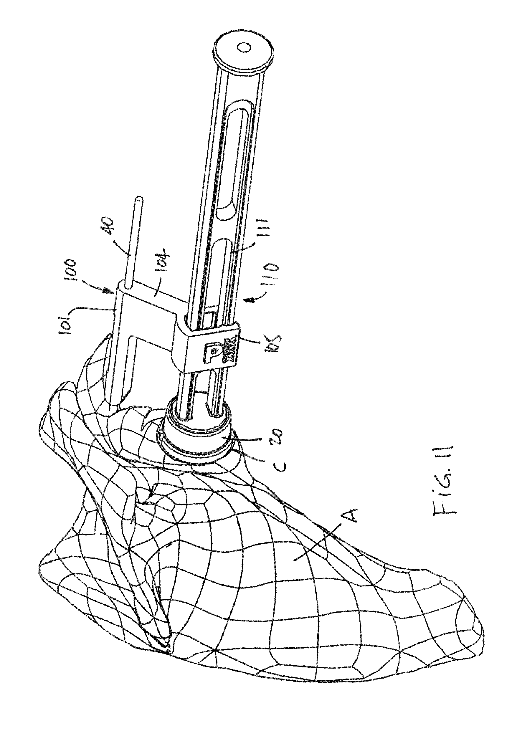
FIG. 11 is a perspective view of the scapula with the impactor guide PSI and impactor tool;
FIG. 12 is a perspective view of a drilling guide PSI in accordance with yet another embodiment of the present disclosure;
FIG. 13 is a perspective view of the scapula with the drilling guide PSI and drill bit;
FIG. 14 is an assembly view of a glenoid hemispherical implant;
FIG. 15 is a perspective view of a scapula with a glenoid implant and a graft; and
FIG. 16 is a lateral view of a pin placement PSI of FIG. 4, on the scapula.
DESCRIPTION OF THE EXEMPLARY EMBODIMENTS
Referring to the drawings and more particularly to FIG. 1, there is illustrated at 10 a method for securing a glenoid implant on a scapula (i.e., scapula) In order to perform the method, patient specific instrumentation of various kinds are used, and will be referred to hereinafter as PSI, with reference to FIGS. 2-13. By way of example, FIG. 2 features the positioning of a glenoid hemispherical head implant base on the scapula, in reverse total shoulder surgery. However, the method 10 may alternatively be used to secure a cup implant in the glenoid as performed on anatomic total shoulder replacement.
According to step 11 of FIG. 1, virtual shoulder surgery planning is performed. In this planning step, various shoulder structures are displayed as three-dimensional models, along with a model implant and its components. These 3-D models are typically the result of the processing pre-operative imagery (e.g., CT scans, MRI, etc) and hence are a precise and accurate representation of a patient's bones.
During the planning step, the operator may select various types and dimensions of implants and interactively plan where the implant and its components will be located on the scapula and humerus. In the case of the glenoid implant, the position and orientation thereof may include a virtual representation of the position and orientation of the screws that will secure the glenoid implant to the scapula. Due to the length of the screws and the thinness of the scapula medial to the glenoid, the virtual planning of the location of the glenoid implant typically aims at finding an orientation and depth for the screws that will not have them pierce through the bone material.
For example, there is illustrated at FIG. 2 a model of the scapula A of the patient with parts of an implant 20 (also shown in FIG. 14), the implant 20 being of the ball head type (i.e., a hemispherical head 20A). The implant 20 comprises a base plate 21. The base plate 21 is of the type made of a metal that will be adhered and fitted in a resurfaced glenoid cavity C (FIG. 9). For instance, a trabecular-like medical grade metal may be used for the base plate 21. A peg 22 projects from an underside of the base plate 21 and will be accommodated in a bore drilled in the glenoid cavity B. Screws 23 also project from the underside of the base plate 21 and anchor the implant 20 to the scapula A. A body 25 is secured to the base plate 21, as these parts are generally monolithic The body 25 is the interface of the implant 20 with a hemispherical ball head that will define the surface contacting the humerus or implant thereon. Throughbores 26 are hence concurrently defined in the body 25 and base plate 21, with the screws 23 passing through these throughbores 26.
Steps 12 to 17 of the method 10 are used to guide the surgeon or operator in performing bone alterations so as to replicate the virtual shoulder surgery planning of step 11. Hence, steps 12 to 17 the method 10 are performed to ensure that the glenoid implant is installed substantially similarly to the virtual planning.
According to step 12, PSI are generated using the data obtained from the virtual planning. The PSI will be described in further detail hereinafter. Any appropriate manufacturing method and materials may be used for the PSI, provided that the PSI are precise and accurate representations of the PSI required as a result of the virtual planning. The generation of PSI according to step 12 is performed preoperatively using the imagery data that is also used for the step 11 of virtual shoulder surgery planning. Any other source of anatomical data may also be used, such as manual bone measurements, obtained preoperatively. Another information that may be obtained via the planning step is the generation of a required graft. It may be required to use a graft wedge B1 between the implant and the scapula, and the planning step may therefore define a model of required graft, as shown in FIG. 15, as well as a PSI tool to shape the graft wedge B1 to a predetermined geometry calculated in the virtual planning. The graft wedge B1 would be positioned between the implant 20 and the machined glenoid cavity C. The use of a graft may be required for scapulas limited to a shallow glenoid cavity C, i.e., that does not have a full counterbore shape. Hence, as shown in FIG. 15, the graft wedge B1 would form concurrently with the cavity C the surface against which the implant 20 is applied.
Steps 13 to 17 are performed intra-operatively. The steps are performed once the shoulder joint has been exposed and the humerus has been dislocated, resected and/or separated from the scapula A (FIG. 2).
According to step 13 (FIG. 1), a pair of pins are placed in the scapula A using PSI. Referring concurrently to FIGS. 3 and 4, a pin placement PSI is generally shown at 30. The pin placement PSI 30 comprises an anatomical interface 31. The anatomical interface 31 has a laterally opened hook-like shape so as to receive therein both sides of the scapula head and/or neck of the glenoid B. In accordance with PSI, the anatomical interface 31 has a contact surface(s) 32 that is manufactured to match the corresponding surface on the patient's scapula. Accordingly, the positioning of the pin placement PSI 30 will be guided by the contact surface 32 finding its corresponding matching surface on the scapula A.
The pin placement PSI 30 further comprises a drill guide 33. The drill guide 33 is positioned relative to the anatomical interface 31 as a function of the virtual planning of step 11 (FIG. 1). The drill guide 33 has a pair of cylindrical cutouts or slots 34 that are specifically positioned and oriented to guide the drilling of the pins in the glenoid B, i.e., the slots 34 extend in the longitudinal direction of the PSI 30. According to an embodiment, lateral openings 35 allow lateral access to the slots 34 such that the pins may be laterally inserted into the slots 34. A socket 36 or like connector may also defined in the drill guide 33 to facilitate the manipulation of the pin placement PSI 30. For instance, an elongated tool may be connected to the pin placement PSI 30 by way of the socket 36, for its distal manipulation.
As shown concurrently in FIGS. 4 and 5, pins 40 are drilled into the scapula A. The pins 40 may be provided with sleeves 41 (a.k.a., bushings) received in a planned fit (e.g., precise fit) that will ensure that the pins 40 are axially centered in the slots 34, as the sleeves 41 have throughbores centered with the slots 34. Moreover, the sleeves 41 may comprise abutment ends 42 to control the depth of insertion of the pins 40 in the glenoid. Any appropriate methods are also considered to control the depth of insertion of the pins 40, such as graduating the pins 40 with a scale, etc.
In operation, handle 43 is connected to the socket (FIGS. 3 and 4), and the pin placement PSI 30 is installed onto the glenoid B with the anatomical interface ensuring that the pin placement PSI 30 is properly positioned on the scapula A, by laterally moving the pin placement PSI 30 into planned position on the bone. The pins 40 with sleeves 41 thereon are inserted in the slots 34 of the pin placement PSI via the lateral openings 35, and may hence be drilled into the glenoid B, or the sleeves/bushings 41 may be placed in the slots 34 prior to threading the pins 40 therein. Once the pins 40 are suitably inserted in the scapula A, the sleeves 41 may be withdrawn by sliding them off the end of the pins 40 shown in FIG. 5, thereby allowing the removal of the pin placement PSI 30 from the scapula A by a lateral movement. The surfaces of the hook-like portion of the anatomical interface 31 are generally transverse to a longitudinal direction of the drill guide 33. The presence of the lateral openings 35 allows a good contact surface between the hook-like portion of the anatomical interface 31, without having difficulties in the lateral withdrawal of the PSI 30 as the pins 40 pass through the lateral openings 35.
According to the illustrated embodiment, one of the pins 40 is at a center of the anticipated resurfaced glenoid cavity C, while the other pin 40 is located adjacent to the superior glenoid rim in alignment with the coracoid or at the base of the coracoid. Other positions are also considered. For illustrative purposes, a contemplated position of the pin placement PSI 30 is generally shown relative to the scapula A in FIG. 16.
Referring to FIG. 1, a step 14 of depth drilling and/or surface reaming on the glenoid B is performed using the pins 40 and an appropriate PSI. Referring concurrently to FIGS. 6 and 7, a reaming PSI is generally shown at 60. The reaming PSI 60 has a first tube 61 with a pin slot 62 that is dimensioned to be slid onto one of the pins 40, thereby forming a cylindrical joint therewith. An end of the first tube 61 defines an abutment 63 to abut against the scapula A. A spacing arm 64 extends laterally from the first tube 61 and has at its free end a second tube 65. The second tube 65 also comprises a shaft slot 66, which shaft slot 66 is laterally accessible via a lateral opening 67, used to rotate the reaming PSI 60 such that the pin 40 enters the shaft slot 66. As the reaming PSI 60 is patient specific, the pin slots 62 and the shaft slot 66 are spaced apart by a predetermined distance to match the spacing between the pins 40. Hence, as shown in FIG. 7, when the first tube 61 is slid onto one of the pins 40, the other pin 40 may be oriented to be within the shaft slot 66 of the second tube 65.
It is pointed out that step 14 may comprise a verification of the location of the pins 40. As the reaming PSI 60 is fabricated to receive the pins 40, the centrally-located pin 40 should be axially centered in the second tube 65. Any off-centering may indicate improper positioning of the pin 40, and such indication may cause a review of step 13 to reposition the pins 40.
Referring to FIG. 8, a cannulated reamer 80 may therefore be installed onto the pin 40 that is within the shaft slot 66, so as to be coaxially guided by the pin 40 in translation. The reamer 80 has a reamer end 81 that is selected to perform resurfacing of a planned diameter in the glenoid B. The reamer end 81 is located at the end of a shaft 82. The shaft 82 is sized to be received in the shaft slot 66 of the reaming PSI 60, to form the translational joint. Moreover, the reamer end 81 may also drill a bore of sufficient diameter to receive the peg 22 of the implant 20 therein (
D00000
D00001
D00002
D00003
D00004
D00005
D00006
D00007
D00008
D00009
D00010
D00011
D00012

D00013

D00014

D00015

D00016

XML
uspto.report is an independent third-party trademark research tool that is not affiliated, endorsed, or sponsored by the United States Patent and Trademark Office (USPTO) or any other governmental organization. The information provided by uspto.report is based on publicly available data at the time of writing and is intended for informational purposes only.
While we strive to provide accurate and up-to-date information, we do not guarantee the accuracy, completeness, reliability, or suitability of the information displayed on this site. The use of this site is at your own risk. Any reliance you place on such information is therefore strictly at your own risk.
All official trademark data, including owner information, should be verified by visiting the official USPTO website at www.uspto.gov. This site is not intended to replace professional legal advice and should not be used as a substitute for consulting with a legal professional who is knowledgeable about trademark law.