System and method for obtaining micro-service telemetry data
Nainar , et al. Ja
U.S. patent number 10,541,893 [Application Number 15/793,557] was granted by the patent office on 2020-01-21 for system and method for obtaining micro-service telemetry data. This patent grant is currently assigned to CISCO TECHNOLOGY, INC.. The grantee listed for this patent is Cisco Technology, Inc.. Invention is credited to Rajiv Asati, Nagendra Kumar Nainar, Carlos M. Pignataro.


| United States Patent | 10,541,893 |
| Nainar , et al. | January 21, 2020 |
System and method for obtaining micro-service telemetry data
Abstract
Systems, methods, and computer-readable media are disclosed for use of an overlay network termination endpoint as a proxy to collect telemetry data for micro-services or specific applications provided by containers in overlay data centers. In one aspect of the present disclosure, a method includes receiving, at a controller, a probe for flow statistics associated with a service path, the probe including corresponding flow identification information, extracting the corresponding flow identification information from the probe, obtaining the flow statistics from an agent based on the flow identification information, the agent being configured to manage a plurality of containers, generating a response packet including the flow statistics obtained from the agent and sending the response packet to an initiator from which the query is received.
| Inventors: | Nainar; Nagendra Kumar (Morrisville, NC), Asati; Rajiv (Morrisville, NC), Pignataro; Carlos M. (Cary, CA) | ||||||||||
|---|---|---|---|---|---|---|---|---|---|---|---|
| Applicant: |
|
||||||||||
| Assignee: | CISCO TECHNOLOGY, INC. (San
Jose, CA) |
||||||||||
| Family ID: | 66171277 | ||||||||||
| Appl. No.: | 15/793,557 | ||||||||||
| Filed: | October 25, 2017 |
Prior Publication Data
| Document Identifier | Publication Date | |
|---|---|---|
| US 20190123984 A1 | Apr 25, 2019 | |
| Current U.S. Class: | 1/1 |
| Current CPC Class: | H04L 43/026 (20130101); H04L 43/062 (20130101); H04L 43/12 (20130101); H04L 43/0876 (20130101); H04L 43/04 (20130101) |
| Current International Class: | G06F 15/173 (20060101); H04L 12/26 (20060101) |
| Field of Search: | ;709/203,206,217,219,223,224,226,228,230,232,238 ;714/32 ;370/235,395.5 ;1/1 |
References Cited [Referenced By]
U.S. Patent Documents
| 3629512 | December 1971 | Yuan |
| 4769811 | September 1988 | Eckberg, Jr. et al. |
| 5408231 | April 1995 | Bowdon |
| 5491690 | February 1996 | Alfonsi et al. |
| 5557609 | September 1996 | Shobatake et al. |
| 5600638 | February 1997 | Bertin et al. |
| 5687167 | November 1997 | Bertin et al. |
| 6115384 | September 2000 | Parzych |
| 6167438 | December 2000 | Yates et al. |
| 6400681 | June 2002 | Bertin et al. |
| 6430160 | August 2002 | Smith |
| 6661797 | December 2003 | Goel et al. |
| 6687229 | February 2004 | Kataria et al. |
| 6799270 | September 2004 | Bull et al. |
| 6888828 | May 2005 | Partanen et al. |
| 6993593 | January 2006 | Iwata |
| 7027408 | April 2006 | Nabkel et al. |
| 7062567 | June 2006 | Benitez et al. |
| 7095715 | August 2006 | Buckman et al. |
| 7096212 | August 2006 | Tribble et al. |
| 7139239 | November 2006 | McFarland et al. |
| 7165107 | January 2007 | Pouyoul et al. |
| 7197008 | March 2007 | Shabtay et al. |
| 7197660 | March 2007 | Liu et al. |
| 7209435 | April 2007 | Kuo et al. |
| 7227872 | June 2007 | Biswas et al. |
| 7231462 | June 2007 | Berthaud et al. |
| 7333990 | February 2008 | Thiagarajan et al. |
| 7443796 | October 2008 | Albert et al. |
| 7458084 | November 2008 | Zhang et al. |
| 7472411 | December 2008 | Wing et al. |
| 7486622 | February 2009 | Regan et al. |
| 7536396 | May 2009 | Johnson et al. |
| 7552201 | June 2009 | Areddu et al. |
| 7558261 | July 2009 | Arregoces et al. |
| 7567504 | July 2009 | Darling et al. |
| 7571470 | August 2009 | Arregoces et al. |
| 7573879 | August 2009 | Narad et al. |
| 7610375 | October 2009 | Portolani et al. |
| 7643468 | January 2010 | Arregoces et al. |
| 7644182 | January 2010 | Banerjee et al. |
| 7647422 | January 2010 | Singh et al. |
| 7657898 | February 2010 | Sadiq |
| 7657940 | February 2010 | Portolani et al. |
| 7668116 | February 2010 | Wijnands et al. |
| 7684321 | March 2010 | Muirhead et al. |
| 7738469 | June 2010 | Shekokar et al. |
| 7751409 | July 2010 | Carolan |
| 7793157 | September 2010 | Bailey et al. |
| 7814284 | October 2010 | Glass et al. |
| 7831693 | November 2010 | Lai |
| 7852785 | December 2010 | Lund et al. |
| 7860095 | December 2010 | Forissier et al. |
| 7860100 | December 2010 | Khalid et al. |
| 7895425 | February 2011 | Khalid et al. |
| 7899012 | March 2011 | Ho et al. |
| 7899861 | March 2011 | Feblowitz et al. |
| 7907595 | March 2011 | Khanna et al. |
| 7908480 | March 2011 | Firestone et al. |
| 7940685 | May 2011 | Breslau |
| 7983174 | July 2011 | Monaghan et al. |
| 7990847 | August 2011 | Leroy et al. |
| 8000329 | August 2011 | Fendick et al. |
| 8018938 | September 2011 | Fromm et al. |
| 8094575 | January 2012 | Vadlakonda et al. |
| 8095683 | January 2012 | Balasubramanian Chandra |
| 8116307 | February 2012 | Thesayi et al. |
| 8166465 | April 2012 | Feblowitz et al. |
| 8180909 | May 2012 | Hartman et al. |
| 8191119 | May 2012 | Wing et al. |
| 8195774 | June 2012 | Lambeth et al. |
| 8280354 | October 2012 | Smith et al. |
| 8281302 | October 2012 | Durazzo et al. |
| 8291108 | October 2012 | Raja et al. |
| 8305900 | November 2012 | Bianconi |
| 8311045 | November 2012 | Quinn et al. |
| 8316457 | November 2012 | Paczkowski et al. |
| 8355332 | January 2013 | Beaudette et al. |
| 8442043 | May 2013 | Sharma et al. |
| 8451817 | May 2013 | Cheriton |
| 8464336 | June 2013 | Wei et al. |
| 8473981 | June 2013 | Gargi |
| 8479298 | July 2013 | Keith et al. |
| 8498414 | July 2013 | Rossi |
| 8520672 | August 2013 | Guichard et al. |
| 8601152 | December 2013 | Chou |
| 8605588 | December 2013 | Sankaran et al. |
| 8612612 | December 2013 | Dukes et al. |
| 8627328 | January 2014 | Mousseau et al. |
| 8645952 | February 2014 | Biswas et al. |
| 8676965 | March 2014 | Gueta |
| 8676980 | March 2014 | Kreeger et al. |
| 8700892 | April 2014 | Bollay et al. |
| 8724466 | May 2014 | Kenigsberg et al. |
| 8730980 | May 2014 | Bagepalli et al. |
| 8743885 | June 2014 | Khan et al. |
| 8751420 | June 2014 | Hjelm et al. |
| 8762534 | June 2014 | Hong et al. |
| 8762707 | June 2014 | Killian et al. |
| 8792490 | July 2014 | Jabr et al. |
| 8793400 | July 2014 | McDysan et al. |
| 8812730 | August 2014 | Vos et al. |
| 8819419 | August 2014 | Carlson et al. |
| 8825070 | September 2014 | Akhtar et al. |
| 8830834 | September 2014 | Sharma et al. |
| 8904037 | December 2014 | Haggar et al. |
| 8984284 | March 2015 | Purdy, Sr. et al. |
| 9001827 | April 2015 | Appenzeller |
| 9071533 | June 2015 | Hui et al. |
| 9077661 | July 2015 | Andreasen et al. |
| 9088584 | July 2015 | Feng et al. |
| 9130872 | September 2015 | Kumar et al. |
| 9143438 | September 2015 | Khan et al. |
| 9160797 | October 2015 | McDysan |
| 9178812 | November 2015 | Guichard et al. |
| 9189285 | November 2015 | Ng et al. |
| 9203711 | December 2015 | Agarwal et al. |
| 9253274 | February 2016 | Quinn et al. |
| 9300579 | March 2016 | Frost et al. |
| 9300585 | March 2016 | Kumar et al. |
| 9311130 | April 2016 | Christenson et al. |
| 9319324 | April 2016 | Beheshti-Zavareh et al. |
| 9325565 | April 2016 | Yao et al. |
| 9338097 | May 2016 | Anand et al. |
| 9344337 | May 2016 | Kumar et al. |
| 9374297 | June 2016 | Bosch et al. |
| 9379931 | June 2016 | Bosch et al. |
| 9385950 | July 2016 | Quinn et al. |
| 9398486 | July 2016 | La Roche, Jr. et al. |
| 9407540 | August 2016 | Kumar et al. |
| 9413655 | August 2016 | Shatzkamer et al. |
| 9424065 | August 2016 | Singh et al. |
| 9436443 | September 2016 | Chiosi et al. |
| 9444675 | September 2016 | Guichard et al. |
| 9473570 | October 2016 | Bhanujan et al. |
| 9479443 | October 2016 | Bosch et al. |
| 9491094 | November 2016 | Patwardhan et al. |
| 9537836 | January 2017 | Maller et al. |
| 9558029 | January 2017 | Behera et al. |
| 9559970 | January 2017 | Kumar et al. |
| 9571405 | February 2017 | Pignataro et al. |
| 9608896 | March 2017 | Kumar et al. |
| 9614739 | April 2017 | Kumar et al. |
| 9660909 | May 2017 | Guichard et al. |
| 9723106 | August 2017 | Shen et al. |
| 9774533 | September 2017 | Zhang et al. |
| 9794379 | October 2017 | Kumar et al. |
| 9882776 | January 2018 | Aybay et al. |
| 9929945 | March 2018 | Schultz et al. |
| 10003530 | June 2018 | Zhang et al. |
| 2001/0023442 | September 2001 | Masters |
| 2002/0085562 | July 2002 | Hufferd et al. |
| 2002/0131362 | September 2002 | Callon |
| 2002/0156893 | October 2002 | Pouyoul et al. |
| 2002/0167935 | November 2002 | Nabkel et al. |
| 2003/0023879 | January 2003 | Wray |
| 2003/0026257 | February 2003 | Xu et al. |
| 2003/0037070 | February 2003 | Marston |
| 2003/0088698 | May 2003 | Singh et al. |
| 2003/0110081 | June 2003 | Tosaki et al. |
| 2003/0120816 | June 2003 | Berthaud et al. |
| 2003/0214913 | November 2003 | Kan et al. |
| 2003/0226142 | December 2003 | Rand |
| 2004/0109412 | June 2004 | Hansson et al. |
| 2004/0148391 | July 2004 | Lake, Sr. et al. |
| 2004/0199812 | October 2004 | Earl |
| 2004/0213160 | October 2004 | Regan et al. |
| 2004/0264481 | December 2004 | Darling et al. |
| 2004/0268357 | December 2004 | Joy et al. |
| 2005/0044197 | February 2005 | Lai |
| 2005/0058118 | March 2005 | Davis |
| 2005/0060572 | March 2005 | Kung |
| 2005/0086367 | April 2005 | Conta et al. |
| 2005/0120101 | June 2005 | Nocera |
| 2005/0152378 | July 2005 | Bango et al. |
| 2005/0157645 | July 2005 | Rabie et al. |
| 2005/0160180 | July 2005 | Rabje et al. |
| 2005/0204042 | September 2005 | Banerjee et al. |
| 2005/0210096 | September 2005 | Bishop et al. |
| 2005/0257002 | November 2005 | Nguyen |
| 2005/0281257 | December 2005 | Yazaki et al. |
| 2005/0286540 | December 2005 | Hurtta et al. |
| 2005/0289244 | December 2005 | Sahu et al. |
| 2006/0005240 | January 2006 | Sundarrajan et al. |
| 2006/0031374 | February 2006 | Lu et al. |
| 2006/0045024 | March 2006 | Previdi et al. |
| 2006/0074502 | April 2006 | McFarland |
| 2006/0092950 | May 2006 | Arregoces et al. |
| 2006/0095960 | May 2006 | Arregoces et al. |
| 2006/0112400 | May 2006 | Zhang et al. |
| 2006/0155862 | July 2006 | Kathi et al. |
| 2006/0168223 | July 2006 | Mishra et al. |
| 2006/0233106 | October 2006 | Achlioptas et al. |
| 2006/0233155 | October 2006 | Srivastava |
| 2006/0291473 | December 2006 | Chase |
| 2007/0061441 | March 2007 | Landis et al. |
| 2007/0067435 | March 2007 | Landis et al. |
| 2007/0094397 | April 2007 | Krelbaum et al. |
| 2007/0143851 | June 2007 | Nicodemus et al. |
| 2007/0237147 | October 2007 | Quinn et al. |
| 2007/0250836 | October 2007 | Li et al. |
| 2008/0056153 | March 2008 | Liu |
| 2008/0080509 | April 2008 | Khanna et al. |
| 2008/0080517 | April 2008 | Roy et al. |
| 2008/0170542 | July 2008 | Hu |
| 2008/0177896 | July 2008 | Quinn et al. |
| 2008/0181118 | July 2008 | Sharma et al. |
| 2008/0196083 | August 2008 | Parks et al. |
| 2008/0209039 | August 2008 | Tracey et al. |
| 2008/0219287 | September 2008 | Krueger et al. |
| 2008/0225710 | September 2008 | Raja et al. |
| 2008/0291910 | November 2008 | Tadimeti et al. |
| 2009/0003364 | January 2009 | Fendick et al. |
| 2009/0006152 | January 2009 | Timmerman et al. |
| 2009/0037713 | February 2009 | Khalid et al. |
| 2009/0094684 | April 2009 | Chinnusamy et al. |
| 2009/0204612 | August 2009 | Keshavarz-nia et al. |
| 2009/0271656 | October 2009 | Yokota et al. |
| 2009/0300207 | December 2009 | Giaretta et al. |
| 2009/0305699 | December 2009 | Deshpande et al. |
| 2009/0328054 | December 2009 | Paramasivam et al. |
| 2010/0058329 | March 2010 | Durazzo et al. |
| 2010/0063988 | March 2010 | Khalid |
| 2010/0080226 | April 2010 | Khalid |
| 2010/0165985 | July 2010 | Sharma et al. |
| 2010/0191612 | July 2010 | Raleigh |
| 2010/0211658 | August 2010 | Hoogerwerf et al. |
| 2011/0010585 | January 2011 | Bugenhagen |
| 2011/0023090 | January 2011 | Asati et al. |
| 2011/0032833 | February 2011 | Zhang et al. |
| 2011/0055845 | March 2011 | Nandagopal et al. |
| 2011/0131338 | June 2011 | Hu |
| 2011/0137991 | June 2011 | Russell |
| 2011/0142056 | June 2011 | Manoj |
| 2011/0161494 | June 2011 | McDysan et al. |
| 2011/0222412 | September 2011 | Kompella |
| 2011/0255538 | October 2011 | Srinivasan et al. |
| 2011/0267947 | November 2011 | Dhar et al. |
| 2012/0131662 | May 2012 | Kuik et al. |
| 2012/0147894 | June 2012 | Mulligan et al. |
| 2012/0324442 | December 2012 | Barde |
| 2012/0331135 | December 2012 | Alon et al. |
| 2013/0003735 | January 2013 | Chao et al. |
| 2013/0003736 | January 2013 | Szyszko et al. |
| 2013/0040640 | February 2013 | Chen et al. |
| 2013/0044636 | February 2013 | Koponen et al. |
| 2013/0121137 | May 2013 | Feng et al. |
| 2013/0124708 | May 2013 | Lee et al. |
| 2013/0163594 | June 2013 | Sharma et al. |
| 2013/0163606 | June 2013 | Bagepalli et al. |
| 2013/0238806 | September 2013 | Moen |
| 2013/0272305 | October 2013 | Lefebvre et al. |
| 2013/0294236 | November 2013 | Beheshti-Zavareh |
| 2013/0311675 | November 2013 | Kancherla |
| 2013/0329584 | December 2013 | Ghose et al. |
| 2014/0010083 | January 2014 | Hamdi et al. |
| 2014/0010096 | January 2014 | Kamble et al. |
| 2014/0036730 | February 2014 | Nellikar et al. |
| 2014/0050223 | February 2014 | Foo et al. |
| 2014/0067758 | March 2014 | Boldyrev et al. |
| 2014/0105062 | April 2014 | McDysan et al. |
| 2014/0181267 | June 2014 | Wadkins et al. |
| 2014/0254603 | September 2014 | Banavalikar et al. |
| 2014/0259012 | September 2014 | Nandlall et al. |
| 2014/0279863 | September 2014 | Krishnamurthy et al. |
| 2014/0280836 | September 2014 | Kumar et al. |
| 2014/0317261 | October 2014 | Shatzkamer et al. |
| 2014/0321459 | October 2014 | Kumar et al. |
| 2014/0334295 | November 2014 | Guichard et al. |
| 2014/0344439 | November 2014 | Kempf et al. |
| 2014/0362682 | December 2014 | Guichard et al. |
| 2014/0362857 | December 2014 | Guichard et al. |
| 2014/0369209 | December 2014 | Khurshid et al. |
| 2014/0376558 | December 2014 | Rao et al. |
| 2015/0003455 | January 2015 | Haddad et al. |
| 2015/0012584 | January 2015 | Lo et al. |
| 2015/0012988 | January 2015 | Jeng et al. |
| 2015/0029871 | January 2015 | Frost et al. |
| 2015/0032871 | January 2015 | Allan et al. |
| 2015/0052516 | February 2015 | French et al. |
| 2015/0071285 | March 2015 | Kumar et al. |
| 2015/0074276 | March 2015 | DeCusatis et al. |
| 2015/0082308 | March 2015 | Kiess et al. |
| 2015/0085635 | March 2015 | Wijnands et al. |
| 2015/0085870 | March 2015 | Narasimha et al. |
| 2015/0089082 | March 2015 | Patwardhan et al. |
| 2015/0092564 | April 2015 | Aldrin |
| 2015/0103827 | April 2015 | Quinn et al. |
| 2015/0117308 | April 2015 | Kant |
| 2015/0124622 | May 2015 | Kovvali et al. |
| 2015/0131484 | May 2015 | Aldrin |
| 2015/0131660 | May 2015 | Shepherd et al. |
| 2015/0156035 | June 2015 | Foo et al. |
| 2015/0180725 | June 2015 | Varney et al. |
| 2015/0180767 | June 2015 | Tam et al. |
| 2015/0181309 | June 2015 | Shepherd et al. |
| 2015/0188949 | July 2015 | Mahaffey et al. |
| 2015/0195197 | July 2015 | Yong et al. |
| 2015/0222516 | August 2015 | Deval et al. |
| 2015/0222533 | August 2015 | Birrittella et al. |
| 2015/0236948 | August 2015 | Dunbar et al. |
| 2015/0319078 | November 2015 | Lee et al. |
| 2015/0319081 | November 2015 | Kasturi et al. |
| 2015/0326473 | November 2015 | Dunbar et al. |
| 2015/0333930 | November 2015 | Aysola et al. |
| 2015/0334027 | November 2015 | Bosch et al. |
| 2015/0341285 | November 2015 | Aysola et al. |
| 2015/0365495 | December 2015 | Fan et al. |
| 2015/0381465 | December 2015 | Narayanan et al. |
| 2015/0381557 | December 2015 | Fan et al. |
| 2016/0028604 | January 2016 | Chakrabarti et al. |
| 2016/0028640 | January 2016 | Zhang et al. |
| 2016/0043952 | February 2016 | Zhang et al. |
| 2016/0050117 | February 2016 | Voellmy et al. |
| 2016/0050132 | February 2016 | Zhang |
| 2016/0080263 | March 2016 | Park et al. |
| 2016/0099853 | April 2016 | Nedeltchev et al. |
| 2016/0119159 | April 2016 | Zhao et al. |
| 2016/0119253 | April 2016 | Kang et al. |
| 2016/0127139 | May 2016 | Tian et al. |
| 2016/0134518 | May 2016 | Callon et al. |
| 2016/0134535 | May 2016 | Callon |
| 2016/0139939 | May 2016 | Bosch et al. |
| 2016/0164776 | June 2016 | Biancaniello |
| 2016/0165014 | June 2016 | Nainar et al. |
| 2016/0173373 | June 2016 | Guichard et al. |
| 2016/0173464 | June 2016 | Wang et al. |
| 2016/0182336 | June 2016 | Doctor et al. |
| 2016/0182342 | June 2016 | Singaravelu et al. |
| 2016/0182684 | June 2016 | Connor et al. |
| 2016/0212017 | July 2016 | Li et al. |
| 2016/0226742 | August 2016 | Apathotharanan et al. |
| 2016/0248685 | August 2016 | Pignataro et al. |
| 2016/0277250 | September 2016 | Maes |
| 2016/0285720 | September 2016 | Maenpaaet al. |
| 2016/0323165 | November 2016 | Boucadair et al. |
| 2016/0352629 | December 2016 | Wang et al. |
| 2016/0380966 | December 2016 | Gunnalan et al. |
| 2017/0019303 | January 2017 | Swamy et al. |
| 2017/0031804 | February 2017 | Ciszewski et al. |
| 2017/0078175 | March 2017 | Xu et al. |
| 2017/0126475 | May 2017 | Mahkonen |
| 2017/0187609 | June 2017 | Lee et al. |
| 2017/0208000 | July 2017 | Bosch et al. |
| 2017/0214627 | July 2017 | Zhang et al. |
| 2017/0237656 | August 2017 | Gage et al. |
| 2017/0250917 | August 2017 | Ruckstuhl et al. |
| 2017/0272470 | September 2017 | Gundamaraju et al. |
| 2017/0279712 | September 2017 | Nainar et al. |
| 2017/0310611 | October 2017 | Kumar et al. |
| 2017/0331741 | November 2017 | Fedyk et al. |
| 2017/0353383 | December 2017 | Hughes |
| 2018/0013841 | January 2018 | Nainar et al. |
| 2018/0026884 | January 2018 | Nainar et al. |
| 2018/0026887 | January 2018 | Nainar et al. |
| 2018/0041470 | February 2018 | Schultz et al. |
| 2018/0062991 | March 2018 | Nainar et al. |
| 103716123 | Apr 2014 | CN | |||
| 103716137 | Apr 2014 | CN | |||
| 3160073 | Apr 2017 | EP | |||
| 2016149686 | Aug 2016 | JP | |||
| WO 2011/029321 | Mar 2011 | WO | |||
| WO 2012/056404 | May 2012 | WO | |||
| WO 2015/065353 | May 2015 | WO | |||
| WO 2015/180559 | Dec 2015 | WO | |||
| WO 2015/187337 | Dec 2015 | WO | |||
| WO 2016/004556 | Jan 2016 | WO | |||
| WO 2016/058245 | Apr 2016 | WO | |||
| WO 2017/011607 | Jan 2017 | WO | |||
Other References
|
Alizadeh, Mohammad, et al., "CONGA: Distributed Congestion-Aware Load Balancing for Datacenters," SIGCOMM '14, Aug. 17-22, 2014, 12 pages. cited by applicant . Author Unknown, "IEEE Standard for the Functional Architecture of Next Generation Service Overlay Networks, IEEE Std. 1903-2011," IEEE, Piscataway, NJ, Oct. 7, 2011; 147 pages. cited by applicant . Author Unknown, "OpenNebula 4.6 User Guide," Jun. 12, 2014, opennebula.org, 87 pages. cited by applicant . Author Unknown, "Service-Aware Network Architecture Based on SDN, NFV, and Network Intelligence," 2014, 8 pages. cited by applicant . Bi, Jing, et al., "Dynamic Provisioning Modeling for Virtualized Multi-tier Applications in Cloud Data Center," 2010 IEEE 3.sup.rd International Conference on Cloud Computing, Jul. 5, 2010, pp. 370-377, IEEE Computer Society. cited by applicant . Bitar, N., et al., "Interface to the Routing System (I2RS) for the Service Chaining: Use Cases and Requirements," draft-bitar-i2rs-service-chaining-01, Feb. 14, 2014, pp. 1-15. cited by applicant . Bremler-Barr, Anat, et al., "Deep Packet Inspection as a Service," CoNEXT '14, Dec. 2-5, 2014, pp. 271-282. cited by applicant . Cisco Systems, Inc. "Cisco VN-Link: Virtualization-Aware Networking," 2009, 9 pages. cited by applicant . Dunbar, et al., "Architecture for Chaining Legacy Layer 4-7 Service Functions," IETF Network Working Group Internet Draft, draft-dunbar-sfc-legacy-14-17-chain-architecture-03.txt, Feb. 10, 2014; 17 pages. cited by applicant . Farrel, A., et al., "A Path Computation Element (PCE)--Based Architecture," RFC 4655, Network Working Group, Aug. 2006, 40 pages. cited by applicant . Jiang, Y., et al., "An Architecture of Service Function Chaining," IETF Network Working Group Internet Draft, draft-jiang-sfc-arch-01.txt, Feb. 14, 2014; 12 pages. cited by applicant . Katsikas, Goergios P., et al., "Profiling and accelerating commodity NFV service chains with SCC," The Journal of Systems and Software, vol. 127, Jan. 2017, pp. 12-27. cited by applicant . Kumbhare, Abhijit, et al., "Opendaylight Service Function Chaining Use-Cases," Oct. 14, 2014, 25 pages. cited by applicant . Li, Hongyu, "Service Function Chaining Use Cases", IETF 88 Vancouver, Nov. 7, 2013, 7 pages. cited by applicant . Mortensen, A., et al., "Distributed Denial of Service (DDoS) Open Threat Signaling Requirements," DOTS, Mar. 18, 2016, 16 pages; http://tools.ietf.org/pdf/draft-ietf-dots-requirements-01.pdf. cited by applicant . Newman, David, "Review: FireEye fights off multi-stage malware," Network World, May 5, 2014, 7 pages. cited by applicant . Nguyen, Kim-Khoa, et al. "Distributed Control Plane Architecture of Next Generation IP Routers," IEEE, 2009, 8 pages. cited by applicant . Quinn, P., et al., "Network Service Header," Network Working Group, Mar. 24, 2015, 42 pages; https://tools.ietf.org/pdf/draft-ietf-sfc-nsh-00.pdf. cited by applicant . Quinn, P., et al., "Network Service Chaining Problem Statement," draft-quinn-nsc-problem-statement-03.txt, Aug. 26, 2013, 18 pages. cited by applicant . Quinn, Paul, et al., "Service Function Chaining: Creating a Service Plane via Network Service Headers," IEEE Computer Society, 2014, pp. 38-44. cited by applicant . Zhang, Ying, et al. "StEERING: A Software-Defined Networking for Inline Service Chaining," IEEE, 2013, IEEE, page 10 pages. cited by applicant . Aldrin, S., et al. "Service Function Chaining Operation, Administration and Maintenance Framework," Internet Engineering Task Force, Oct. 26, 2014, 13 pages. cited by applicant . Author Unknown, "ANSI/SCTE 35 2007 Digital Program Insertion Cueing Message for Cable," Engineering Committee, Digital Video Subcommittee, American National Standard, Society of Cable Telecommunications Engineers, .COPYRGT.Society of Cable Telecommunications Engineers, Inc. 2007 All Rights Reserved, 140 Philips Road, Exton, PA 19341; 42 pages. cited by applicant . Author Unknown, "AWS Lambda Developer Guide," Amazon Web Services Inc., May 2017, 416 pages. cited by applicant . Author Unknown, "CEA-708," from Wikipedia, the free encyclopedia, Nov. 15, 2012; 16 pages http://en.wikipedia.org/w/index.php?title=CEA-708&oldid=523143431. cited by applicant . Author Unknown, "Cisco and Intel High-Performance VNFs on Cisco NFV Infrastructure," White Paper, Cisco and Intel, Oct. 2016, 7 pages. cited by applicant . Author Unknown, "Cloud Functions Overview," Cloud Functions Documentation, Mar. 21, 2017, 3 pages; https://cloud.google.com/functions/docs/concepts/overview. cited by applicant . Author Unknown, "Cloud-Native VNF Modelling," Open Source Mano, .COPYRGT.ETSI 2016, 18 pages. cited by applicant . Author Unknown, "Digital Program Insertion," from Wikipedia, the free encyclopedia, Jan. 2, 2012; 1 page http://en.wikipedia.org/w/index.php?title=Digital_Program_Insertion&oldid- =469076482. cited by applicant . Author Unknown, "Dynamic Adaptive Streaming over HTTP," from Wikipedia, the free encyclopedia, Oct. 25, 2012; 3 pages, http://en.wikipedia.org/w/index.php?title=Dynannic_Adaptive_Streanning_ov- er_HTTP&oldid=519749189. cited by applicant . Author Unknown, "GStreamer and in-band metadata," from RidgeRun Developer Connection, Jun. 19, 2012, 5 pages https://developersidgerun.conn/wiki/index.php/GStreanner_and_in-band_nnet- adata. cited by applicant . Author Unknown, "ISO/IEC JTC 1/SC 29, Information Technology--Dynamic Adaptive Streaming over HTTP (DASH)--Part 1: Media Presentation Description and Segment Formats," International Standard .COPYRGT.ISO/IEC 2012--All Rights Reserved; Jan. 5, 2012; 131 pages. cited by applicant . Author Unknown, "M-PEG 2 Transmission," .COPYRGT.Dr. Gorry Fairhurst, 9 pages [Published on or about Jan. 12, 2012] http://www.erg.abdn.ac.uk/future-net/digital-video/mpeg2-trans.html. cited by applicant . Author Unknown, "MPEG Transport Stream," from Wikipedia, the free encyclopedia, Nov. 11, 2012; 7 pages, http://en.wikipedia.org/w/index.php?title=MPEG_transport_streann&oldid=52- 2468296. cited by applicant . Author Unknown, "Network Functions Virtualisation (NFV); Use Cases," ETSI, GS NFV 001 v1.1.1, Architectural Framework, .COPYRGT. European Telecommunications Standards Institute, Oct. 2013, 50 pages. cited by applicant . Author Unknown, "Understanding Azure, A Guide for Developers," Microsoft Corporation, Copyright .COPYRGT. 2016 Microsoft Corporation, 39 pages. cited by applicant . Author Unknown, "3GPP TR 23.803 V7.0.0 (Sep. 2005) Technical Specification: Group Services and System Aspects; Evolution of Policy Control and Charging (Release 7)," 3rd Generation Partnership Project (3GPP), 650 Route des Lucioles--Sophia Antipolis Val bonne--France, Sep. 2005; 30 pages. cited by applicant . Author Unknown, "3GPP TS 23.203 V8.9.0 (Mar. 2010) Technical Specification: Group Services and System Aspects; Policy and Charging Control Architecture (Release 8)," 3rd Generation Partnership Project (3GPP), 650 Route des Lucioles--Sophia Antipolis Val bonne--France, Mar. 2010; 116 pages. cited by applicant . Author Unknown, "3GPP TS 23.401 V13.5.0 (Dec. 2015) Technical Specification: 3rd Generation Partnership Project; Technical Specification Group Services and System Aspects; General Packet Radio Service (GPRS) enhancements for Evolved Universal Terrestrial Radio Access Network (E-UTRAN) access (Release 13)," 3GPP, 650 Route des Lucioles--Sophia Antipolis Valbonne--France, Dec. 2015, 337 pages. cited by applicant . Author Unknown, "3GPP TS 23.401 V9.5.0 (Jun. 2010) Technical Specification: Group Services and Systems Aspects; General Packet Radio Service (GPRS) Enhancements for Evolved Universal Terrestrial Radio Access Network (E-UTRAN) Access (Release 9)," 3rd Generation Partnership Project (3GPP), 650 Route des Lucioles--Sophia Antipolis Valbonne--France, Jun. 2010; 259 pages. cited by applicant . Author Unknown, "3GPP TS 29.212 V13.1.0 (Mar. 2015) Technical Specification: 3rd Generation Partnership Project; Technical Specification Group Core Network and Terminals; Policy and Charging Control (PCC); Reference points (Release 13)," 3rd Generation Partnership Project (3GPP), 650 Route des Lucioles--Sophia Antipolis Valbonne--France, Mar. 2015; 230 pages. cited by applicant . Baird, Andrew, et al. "AWS Serverless Multi-Tier Architectures; Using Amazon API Gateway and AWS Lambda," Amazon Web Services Inc., Nov. 2015, 20 pages. cited by applicant . Boucadair, Mohamed, et al., "Differentiated Service Function Chaining Framework," Network Working Group Internet Draft draft-boucadair-network-function-chaining-03, Aug. 21, 2013, 21 pages. cited by applicant . Cisco Systems, Inc. "Cisco NSH Service Chaining Configuration Guide," Jul. 28, 2017, 11 pages. cited by applicant . Ersue, Mehmet, "ETSI NFV Management and Orchestration-An Overview," Presentation at the IETF# 88 Meeting, Nov. 3, 2013, 14 pages. cited by applicant . Fayaz, Seyed K., et al., "Efficient Network Reachability Analysis using a Succinct Control Plane Representation," 2016, ratul.org, pp. 1-16. cited by applicant . Halpern, Joel, et al., "Service Function Chaining (SFC) Architecture," Internet Engineering Task Force (IETF), Cisco, Oct. 2015, 32 pages. cited by applicant . Hendrickson, Scott, et al. "Serverless Computation with OpenLambda," Elastic 60, University of Wisconson, Madison, Jun. 20, 2016, 7 pages, https://www.usenix.org/system/files/conference/hotcloud16/hotcloud16_ hendrickson.pdf. cited by applicant . Jiang, Yuanlong, et al., "Fault Management in Service Function Chaining," Network Working Group, China Telecom, Oct. 16, 2015, 13 pages. cited by applicant . Kumar, Surendra, et al., "Service Function Path Optimization: draft-kumar-sfc-sfp-optimization-00.txt," Internet Engineering Task Force, IETF; Standard Working Draft, May 10, 2014, 14 pages. cited by applicant . Penno, Reinaldo, et al. "Packet Generation in Service Function Chains," draft-penno-sfc-packet-03, Apr. 29, 2016, 25 pages. cited by applicant . Penno, Reinaldo, et al. "Services Function Chaining Traceroute," draft-penno-sfc-trace-03, Sep. 30, 2015, 9 pages. cited by applicant . Pierre-Louis, Marc-Arhtur, "OpenWhisk: A quick tech preview," DeveloperWorks Open, IBM, Feb. 22, 2016, modified Mar. 3, 2016, 7 pages; https://developer.ibm.com/open/2016/02/22/openwhisk-a-quick-tech-preview/- . cited by applicant . Pujol, Pua Capdevila, "Deployment of NFV and SFC scenarios," EETAC, Master Thesis, Advisor: David Rincon Rivera, Universitat Politecnica De Catalunya, Feb. 17, 2017, 115 pages. cited by applicant . Quinn, Paul, et al., "Network Service Header," Network Working Group, draft-quinn-sfc-nsh-02.txt, Feb. 14, 2014, 21 pages. cited by applicant . Quinn, Paul, et al., "Network Service Header," Network Working Group, draft-quinn-nsh-00.txt, Jun. 13, 2013, 20 pages. cited by applicant . Quinn, Paul, et al., "Network Service Header," Network Working Group Internet Draft draft-quinn-nsh-01, Jul. 12, 2013, 20 pages. cited by applicant . Quinn, Paul, et al., "Service Function Chaining (SFC) Architecture," Network Working Group Internet Draft draft-quinn-sfc-arch-05.txt, May 5, 2014, 31 pages. cited by applicant . Wong, Fei, et al., "SMPTE-TT Embedded in ID3 for HTTP Live Streaming, draft-smpte-id3-http-live-streamirg-00," Informational Internet Draft, Jun. 2012, 7 pages http://tools.ietf.org/htnnl/draft-snnpte-id3-http-live-streaming-00. cited by applicant . Yadav, Rishi, "What Real Cloud-Native Apps Will Look Like," Crunch Network, posted Aug. 3, 2016, 8 pages; https://techcrunch.com/2016/08/03/what-real-cloud-native-apps-will-look-l- ike/. cited by applicant. |
Primary Examiner: Nguyen; Quang N
Attorney, Agent or Firm: Polsinelli PC
Claims
What is claimed is:
1. A method comprising: receiving, at a controller, a probe for flow statistics associated with a service path, the probe including corresponding flow identification information; extracting the corresponding flow identification information from the probe; obtaining the flow statistics from an agent based on the flow identification information, the agent being configured to manage a plurality of containers; generating a response packet including the flow statistics obtained from the agent; and sending the response packet to an initiator from which the query is received.
2. The method of claim 1, wherein the flow identification information includes a flow ID of the service path, a flow label of the service path and an entropy label data of the service path.
3. The method of claim 1, wherein the service path is a path through which a data packet traverses to be serviced by one of the plurality of containers.
4. The method of claim 3, wherein the obtaining comprises: determining a destination container associated with the service path, the destination container being the one of the plurality of containers; generating a query for the flow statistics associated with the destination container, the query including the flow identification information; sending the query to the agent; and receiving a response from the agent including the flow statistics.
5. The method of claim 4, wherein the query includes a source address associated with the controller, a destination address associated with the destination container and entropy details included in the flow identification information.
6. The method of claim 4, wherein the query is a YANG query.
7. The method of claim 4, further comprising: determining a physical host on which the destination container is instantiated; and when the physical host on which the destination container is instantiated is different from a physical host on which the controller is instantiated, modifying the query to include an address of the physical host on which the one of the destination container is instantiated, wherein the sending sends the modified request to an agent running on the physical host on which the destination container is instantiated.
8. The method of claim 4, wherein the sending sends the query to the agent on a south bound API.
9. The method of claim 1, wherein the extracting extracts the flow identification information from a payload of the probe.
10. A system comprising: memory configured to store computer-readable instructions; and one or more processors configured to execute the computer-readable instructions to perform the functions of: receiving a probe for flow statistics associated with a service path, the probe including corresponding flow identification information; extracting the corresponding flow identification information from the probe; obtaining the flow statistics from an agent based on the flow identification information, the agent being configured to manage a plurality of containers; generating a response packet including the flow statistics obtained from the agent; and sending the response packet to an initiator from which the query is received.
11. The system of claim 10, wherein the flow identification information includes a flow ID of the service path, a flow label of the service path and an entropy label data of the service path.
12. The system of claim 10, wherein the service path is a path through which a data packet traverses to be serviced by one of the plurality of containers.
13. The system of claim 12, wherein the one or more processors are configured to execute the computer-readable instructions to perform the function of obtaining by: determining a destination container associated with the service path, the destination container being the one of the plurality of containers; generating a query for the flow statistics associated with the destination container, the query including the flow identification information; sending the query to the agent; and receiving a response from the agent including the flow statistics.
14. The system of claim 13, wherein the query includes a source address associated with the controller, a destination address associated with the destination container and entropy details included in the flow identification information.
15. The system of claim 13, wherein the query is a YANG query.
16. The system of claim 13, wherein the one or more processors are configured to execute the computer-readable instructions to perform the functions of: determining a physical host on which the destination container is instantiated; and when the physical host on which the destination container is instantiated is different from a physical host on which the controller is instantiated, modifying the query to include an address of the physical host on which the one of the destination container is instantiated, wherein the sending sends the modified request to an agent running on the physical host on which the destination container is instantiated.
17. The system of claim 10, wherein the probe is an operation, administration and management (OAM) probe to obtain the flow statistics; and the OAM probe is received from an initiator, the initiator triggering a service function chaining trace to send the OAM probe.
18. One or more non-transitory computer-readable medium having computer-readable instructions stored therein, which when executed by one or more processors, cause the one or more processors to perform the functions of: receiving a probe for flow statistics associated with a service path, the probe including corresponding flow identification information; extracting the corresponding flow identification information from the probe; obtaining the flow statistics from an agent based on the flow identification information, the agent being configured to manage a plurality of containers; generating a response packet including the flow statistics obtained from the agent; and sending the response packet to an initiator from which the query is received.
19. The one or more non-transitory computer-readable medium of claim 18, wherein the execution of the computer-readable instructions cause the one or more processors to perform the function of obtaining by: determining a destination container associated with the service path, the destination container being the one of the plurality of containers; generating a query for the flow statistics associated with the destination container, the query including the flow identification information; sending the query to the agent; and receiving a response from the agent including the flow statistics.
20. The one or more non-transitory computer-readable medium of claim 19, wherein the execution of the computer-readable instructions cause the one or more processors to perform the functions of: determining a physical host on which the destination container is instantiated; and when the physical host on which the destination container is instantiated is different from a physical host on which the controller is instantiated, modifying the query to include an address of the physical host on which the one of the destination container is instantiated, wherein the sending sends the modified request to an agent running on the physical host on which the destination container is instantiated.
Description
The present technology pertains to the use of an overlay network termination endpoint as a proxy to collect telemetry data for micro-services or specific applications provided by containers in overlay data centers.
BACKGROUND
Network Operators use various overlay techniques to collect micro-service or application specific telemetry data such as packet-in, packet-out, etc. For each overlay technique, there are different Operation, Administration and Management (OAM) functionalities available. For example, in a service chaining (SFC) environment, a container can be viewed as service function connected through a service function forwarder. Similarly, in a data center environment, a container can be considered as an end point (application) that is connected through a network virtualization edge (NVE) or other virtual tunnel end point (VTEP). Relevant OAM protocols (e.g., a Unified Overlay OAM protocol extension) can be used to query the telemetry data.
However, the existing OAM techniques require a traffic probe (a probe to collect the telemetry data) to flow over the underlying container to obtain the local statistics. This requires the containers to have the capability to understand the OAM functionality in order to work properly.
BRIEF DESCRIPTION OF THE DRAWINGS
In order to describe the manner in which the above-recited and other advantages and features of the disclosure can be obtained, a more particular description of the principles briefly described above will be rendered by reference to specific embodiments thereof which are illustrated in the appended drawings. Understanding that these drawings depict only exemplary embodiments of the disclosure and are not therefore to be considered to be limiting of its scope, the principles herein are described and explained with additional specificity and detail through the use of the accompanying drawings in which:
FIGS. 1A-D illustrate example network environments and architectures, according to one aspect of the present disclosure;
FIG. 2 illustrates an example network device suitable for performing switching, routing, load balancing, and other networking operations, according to an aspect of the present disclosure;
FIG. 3 illustrates a computing system architecture, according to an aspect of the present disclosure;
FIG. 4 illustrates an example system of service function chaining environment, according to an aspect of the present disclosure;
FIG. 5 describes a method of obtaining telemetry data on containers, according to an aspect of the present disclosure;
FIG. 6 illustrates an example of the process of FIG. 5, according an aspect of the present disclosure; and
FIG. 7 illustrates an example of the process of FIG. 5, according an aspect of the present disclosure.
DESCRIPTION OF EXAMPLE EMBODIMENTS
Various examples of the disclosure are discussed in detail below. While specific implementations are discussed, it should be understood that this is done for illustration purposes only. A person skilled in the relevant art will recognize that other components and configurations may be used without parting from the spirit and scope of the disclosure.
References to one or an example embodiment in the present disclosure can be, but not necessarily are, references to the same example embodiment; and, such references mean at least one of the example embodiments.
Reference to "one example embodiment" or "an example embodiment" means that a particular feature, structure, or characteristic described in connection with the example embodiment is included in at least one example of the disclosure. The appearances of the phrase "in one example embodiment" in various places in the specification are not necessarily all referring to the same example embodiment, nor are separate or alternative example embodiments mutually exclusive of other example embodiments. Moreover, various features are described which may be exhibited by some example embodiments and not by others. Similarly, various features are described which may be features for some example embodiments but not other example embodiments.
The terms used in this specification generally have their ordinary meanings in the art, within the context of the disclosure, and in the specific context where each term is used. Alternative language and synonyms may be used for any one or more of the terms discussed herein, and no special significance should be placed upon whether or not a term is elaborated or discussed herein. Synonyms for certain terms are provided. A recital of one or more synonyms does not exclude the use of other synonyms. The use of examples anywhere in this specification including examples of any terms discussed herein is illustrative only, and is not intended to further limit the scope and meaning of the disclosure or of any exemplified term. Likewise, the disclosure is not limited to various examples given in this specification.
Without intent to limit the scope of the disclosure, examples of instruments, apparatus, methods and their related results according to examples of the present disclosure are given below. Note that titles or subtitles may be used in the examples for convenience of a reader, Which in no way should limit the scope of the disclosure. Unless otherwise defined, technical and scientific terms used herein have the meaning as commonly understood by one of ordinary skill in the art to which this disclosure pertains. In the case of conflict, the present document, including definitions will control.
Although the terms first, second, etc. may be used herein to describe various elements, these elements should not be limited by these terms. These terms are only used to distinguish one element from another. For example, a first element could be termed a second element, and similarly, a second element could be termed a first element, without departing from the scope of this disclosure. As used herein, the term "and/or," includes any and all combinations of one or more of the associated listed items.
When an element is referred to as being "connected," or "coupled," to another element, it can be directly connected or coupled to the other element or intervening elements may be present. By contrast, when an element is referred to as being "directly connected," or "directly coupled," to another dement, there are no intervening elements present. Other words used to describe the relationship between elements should be interpreted in a like fashion (e.g., "between," versus "directly between," "adjacent," versus "directly adjacent," etc.).
The terminology used herein is for the purpose of describing particular examples only and is not intended to be limiting. As used herein, the singular forms "a", "an", and "the" are intended to include the plural forms as well, unless the context clearly indicates otherwise. It will be further understood that the terms "comprises", "comprising", "includes" and/or "including", When used herein, specify the presence of stated features, integers, steps, operations, elements, and/or components, but do not preclude the presence or addition of one or more other features, integers, steps, operations, elements, components, and/or groups thereof.
It should also be noted that in some alternative implementations, the functions/acts noted may occur out of the order noted in the figures. For example, two figures shown in succession may in fact be executed substantially concurrently or may sometimes be executed in the reverse order, depending upon the functionality/acts involved.
Specific details are provided in the following description to provide a thorough understanding of examples. However, it will be understood by one of ordinary skill in the art that examples may be practiced without these specific details. For example, systems may be shown in block diagrams so as not to obscure the examples in unnecessary detail. In other instances, well-known processes, structures and techniques may be shown without unnecessary detail in order to avoid obscuring examples.
In the following description, illustrative examples will be described with reference to acts and symbolic representations of operations (e.g., in the form of flow charts, flow diagrams, data flow diagrams, structure diagrams, block diagrams, etc.) that may be implemented as program services or functional processes include routines, programs, objects, components, data structures, etc., that perform particular tasks or implement particular abstract data types and may be implemented using hardware at network elements. Non-limiting examples of such hardware may include one or more Central Processing Units (CPUs), signal processors (DSPs), application-specific-integrated-circuits, field programmable gate arrays (FPGAs), computers or the like.
Additional features and advantages of the disclosure will be set forth in the description which follows, and in part will be obvious from the description, or can be learned by practice of the herein disclosed principles. The features and advantages of the disclosure can be realized and obtained by means of the instruments and combinations particularly pointed out in the appended claims. These and other features of the disclosure will become more fully apparent from the following description and appended claims, or can be learned by the practice of the principles set forth herein.
Overview
In one aspect of the present disclosure, a method includes receiving, at a controller, a probe for flow statistics associated with a service path, the probe including corresponding flow identification information, extracting the corresponding flow identification information from the probe, obtaining the flow statistics from an agent based on the flow identification information, the agent being configured to manage a plurality of containers, generating a response packet including the flow statistics obtained from the agent and sending the response packet to an initiator from which the query is received.
In one aspect of the present disclosure, a system includes memory configured to store computer-readable instructions and one or more processors configured to execute the computer-readable instructions to perform the functions of receiving a probe for flow statistics associated with a service path, the probe including corresponding flow identification information, extracting the corresponding flow identification information from the probe, obtaining the flow statistics from an agent based on the flow identification information, the agent being configured to manage a plurality of containers, generating a response packet including the flow statistics obtained from the agent; and sending the response packet to an initiator from which the query is received.
In one aspect of the present disclosure, one or more non-transitory computer-readable medium have computer-readable instructions stored therein, which when executed by one or more processors, cause the one or more processors to perform the functions of receiving a probe for flow statistics associated with a service path, the probe including corresponding flow identification information, extracting the corresponding flow identification information from the probe, obtaining the flow statistics from an agent based on the flow identification information, the agent being configured to manage a plurality of containers, generating a response packet including the flow statistics obtained from the agent and sending the response packet to an initiator from which the query is received.
Description
The disclosed technology is directed to the use of an overlay termination endpoint as a proxy such that upon receiving an OAM probe, the proxy obtains flow identification information from the probe to determine a service path to a destination container via a corresponding virtual port that services data (a service function path) and sends queries for statistics/telemetry data on the service function path. The proxy, upon receiving the telemetry data, includes the same in a response to be sent back to an entity (initiator) from which the OAM probe was originally received.
Examples of the present disclosure leverage the use of Contiv HostAgents to collect the requested telemetry data/statistics such that an OAM packet (OAM probe) would no longer have to travel over containers and containers would no longer have to learn, understand and process the OAM functionality.
The disclosure begins with a description of example network environments and architectures, as illustrated in FIGS. 1A-D.
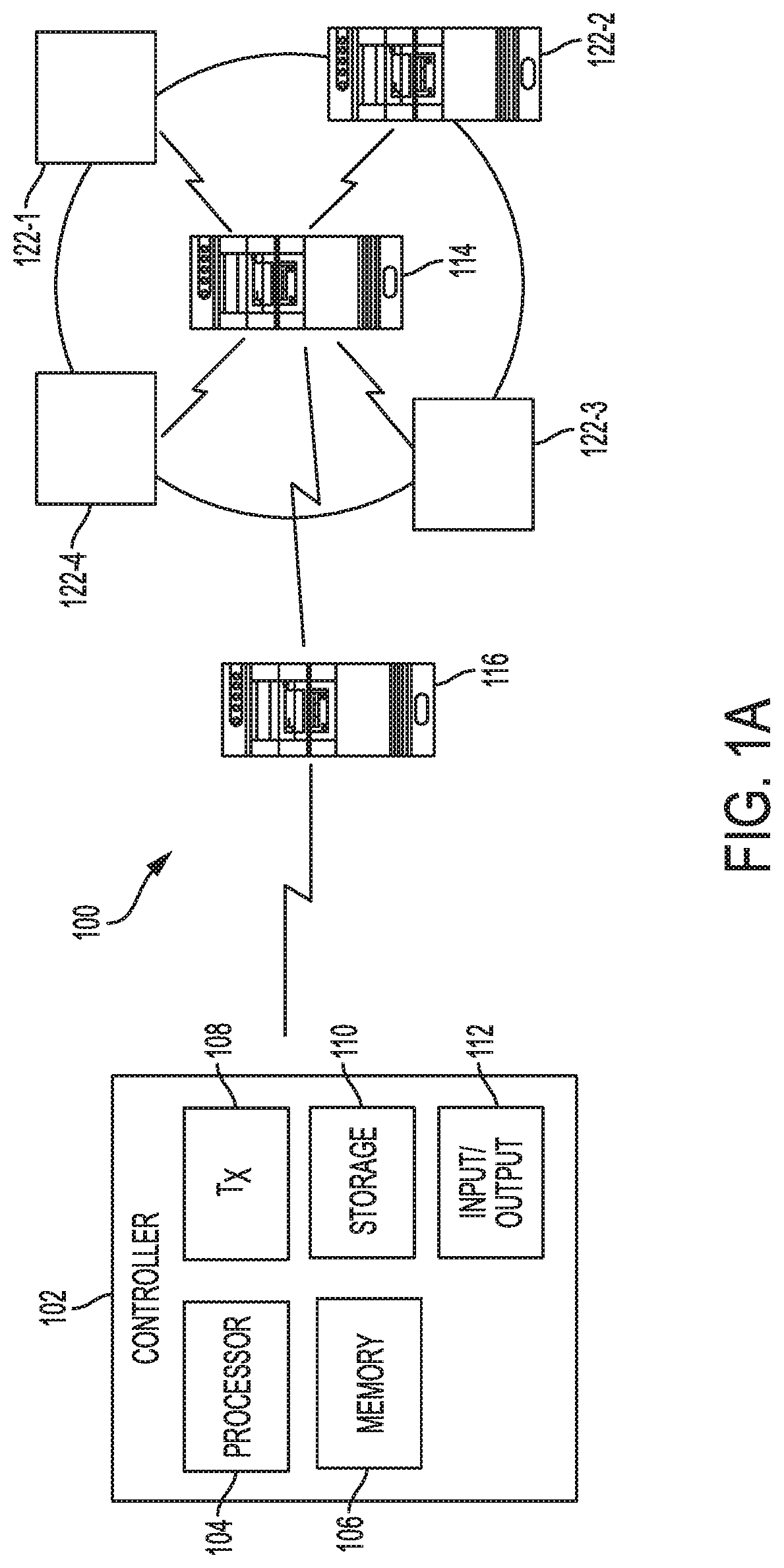
FIG. 1A illustrates an example system, according to one aspect of the present disclosure. System 100 of FIG. 1A includes a controller 102 and a distributed streaming system 120. Controller 102 can be an application, a software container, a virtual machine, a service chain, a virtual function(s), etc. Controller 102 can run on one or more devices or servers having components such as one or more processors (e.g., processor 104), one or more memories (e.g., memory 106), a transceiver 108, a display device 110 and an input device 112. Processor 104 can be configured to execute computer-readable instructions stored on memory 106 for performing the functionalities which will be described below with reference to FIGS. 4-6. Throughout the disclosure, controller 102 can be referred to as system management component 102, management device 102, device 102 and/or system controller 102.
Transceiver 108 can be any known or to be developed receiver and transmitter through Which controller 102 can send and receive information to and from external components such components of distributed streaming system 120.
Network operators and controllers (operational management component) can use display 110 to view data corresponding to status and/or management of operation of distributed streaming system 120, as will be described below. Display 110 can be any type of know or to be developed display such as a liquid crystal display (LCD), a light emitting diode display (LED), etc.
Input device 112 can be any known or to be developed input device including, but not limited to, a keyboard, a touch-based input device, etc. In one example, display 110 and input device 112 can be the same when display 110 is a touch enabled device capable of receiving inputs. Network managers and operators can provide appropriate commands for monitoring and management of distributed streaming system 120, via input device 112.
Controller 102 can communicate with various components of distributed streaming system 120 via any known or to be developed wireless communications and/or wired communications mean. For example, controller 102 can access and obtain information (and/or send information) to each component of distributed system 120 via a network such as a local area wireless network (LAN), a virtual local area network (vLAN) and/or any other type of, known or to be developed, network through which controller 102 can communicate with each component of distributed streaming system 120.
In one aspect, controller 102 can be any known or to be developed electronic device including, but not limited to, a laptop, a desktop computer, a mobile device, a handheld device, etc.
Distributed streaming system 120 can be any known, or to be developed, distributed streaming system where various components thereof such as components 122-1, 122-2, 122-3 and 122-4 communicate with one another to provide a streaming service to users in a distributed fashion. Hereinafter, components 122-1, 122-2, 122-3 and 122-4 may simply be referred to as components 122 or nodes 122. While throughout the present disclosure, distributed streaming system is provided as an example, the present disclosure is not limited thereto and can encompass and be applicable to any distributed systems that can be abstracted into a Directed Acyclic Graph (DAG) where each vertex can denote an information/message, and information/messages are passed through edges in certain directions. Other examples of distributed systems include a distributed sensor network where signals are propagated from sensor to sensor, a multi-component data processing system where each component receives and processes chunks of data and pass it to the next component(s).
Each one of components 122 can be any know or to be developed electronic device capable of communicating remotely with other devices such as other components 122. For example, each component 122 can be a mobile device, a laptop, a desktop computer, a switch, a data center comprising one or more servers, etc. For example, while some of components 122 can be end user devices or hosts, other ones of components 122 can be servers that facilitate the streaming services provided by distributed streaming system 120.
Furthermore, distributed streaming system 120 can have a server 114 acting as a collector of information (data) for other components (end user devices) in the system. Examples of data include device metrics such as device ID, an associated timestamp, device IP address, device throughput, device latency, memory and processing speed characteristics, etc.
In one example, system 100 further includes one or more feedback servers 116, where various types of data (to be used by controller 102) on components 122 can be collected and saved. In another example, system 100 does not include any feedback servers and instead can directly receive (through push or pull operations) the intended data (which will be described below) from each component 122.
Distributed streaming system 120 can be a cloud based system, where each component thereof is located in a different geographical location but can communicate with one another to form distributed streaming system 120 (e.g., over the Internet).
Examples of streaming services provided via distributed streaming system 120 can include, but is not limited to, live video and/or audio content such as a speech, a concert, a TV program, music, etc.
Operations of distributed streaming system 120 for delivering a streaming service to end users can be based on any know or to be developed method for doing so, by for example, continuously processing a stream of text, graphs, videos, audios, time series data, etc. in real time or near real time or periodically. The system 100 of FIG. 1A utilizes client/server based architectures. In other examples, system 100 can be implemented as a cloud or fog computing architecture.
FIG. 1B illustrates a diagram of an example cloud computing architecture 130. The architecture can include a cloud 132. The cloud 132 can include one or more private clouds, public clouds, and/or hybrid clouds. Moreover, the cloud 132 can include cloud elements 134-144. The cloud elements 134-144 can include, for example, servers 134, virtual machines (VMs) 136, one or more software platforms 138, applications or services 140, software containers 142, and infrastructure nodes 144. The infrastructure nodes 144 can include various types of nodes, such as compute nodes, storage nodes, network nodes, management systems, etc. In one example, one or more servers 134 can implement the functionalities of controller 102, which will be described below. Alternatively, controller 102 can be a separate component that communicates with components of the cloud computing architecture 130 that function as a distributed streaming system similar to the distributed streamlining system 120.
The cloud 132 can provide various cloud computing services via the cloud elements 134-144, such as software as a service (SaaS) (e.g., collaboration services, email services, enterprise resource planning services, content services, communication services, etc.), infrastructure as a service (IaaS) (e.g., security services, networking services, systems management services, etc.), platform as a service (PaaS) (e.g., web services, streaming services, application development services, etc.), function as a service (FaaS), and other types of services such as desktop as a service (DaaS), information technology management as a service (ITaaS), managed software as a service (MSaaS), mobile backend as a service (MBaaS), etc.
The client endpoints 146 can connect with the cloud 132 to obtain one or more specific services from the cloud 132. The client endpoints 146 can communicate with elements 134-144 via one or more public networks (e.g., Internet), private networks, and/or hybrid networks (e.g., virtual private network). The client endpoints 146 can include any device with networking capabilities, such as a laptop computer, a tablet computer, a server, a desktop computer, a smartphone, a network device (e.g., an access point, a router, a switch, etc.), a smart television, a smart car, a sensor, a GPS device, a game system, a smart wearable object (e.g., smartwatch, etc.), a consumer object (e.g., Internet refrigerator, smart lighting system, etc.), a city or transportation system (e.g., traffic control, toll collection system, etc.), an Internet of things (IoT) device, a camera, a network printer, a transportation system (e.g., airplane, train, motorcycle, boat, etc.), or any smart or connected object (e.g., smart home, smart building, smart retail, smart glasses, etc.), and so forth.
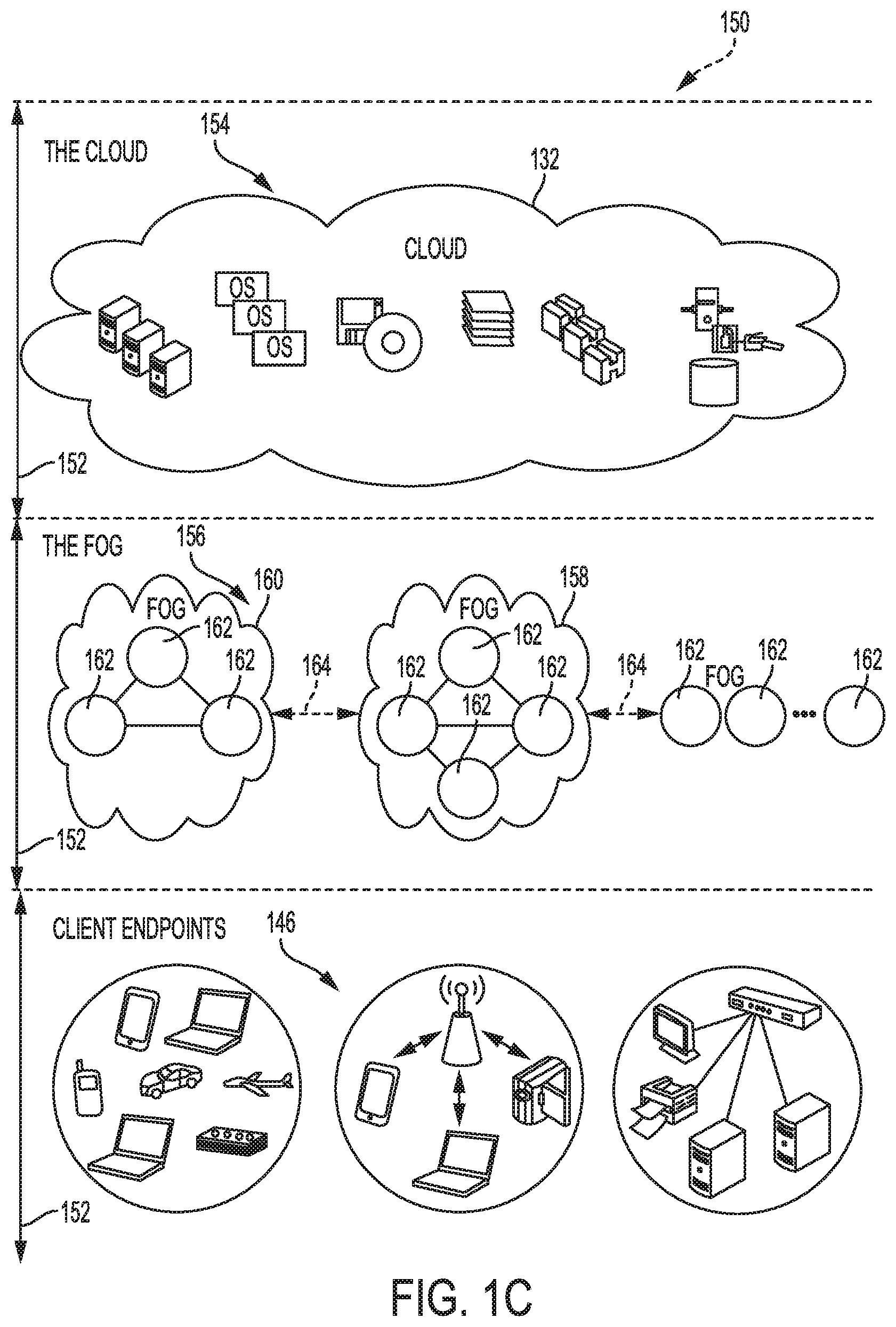
FIG. 1C illustrates a diagram of an example fog computing architecture 150. The fog computing architecture 150 can include the cloud layer 154, which includes the cloud 132 and any other cloud system or environment, and the fog layer 156, which includes fog nodes 162. The client endpoints 146 can communicate with the cloud layer 154 and/or the fog layer 156. The architecture 150 can include one or more communication links 152 between the cloud layer 154, the fog layer 156, and the client endpoints 146. Communications can flow up to the cloud layer 154 and/or clown to the client endpoints 146.
In one example, one or more servers 134 can implement the functionalities of controller 102, which will be described below. Alternatively, controller 102 can be a separate component that communicates with components of the fog computing architecture 150 that function as a distributed streaming system similar to the distributed streamlining system 120
The fog layer 156 or "the fog" provides the computation, storage and networking capabilities of traditional cloud networks, but closer to the endpoints. The fog can thus extend the cloud 132 to be closer to the client endpoints 146. The fog nodes 162 can be the physical implementation of fog networks. Moreover, the fog nodes 162 can provide local or regional services and/or connectivity to the client endpoints 146. As a result, traffic and/or data can be offloaded from the cloud 132 to the fog layer 156 (e.g., via fog nodes 162). The fog layer 156 can thus provide faster services and/or connectivity to the client endpoints 146, with lower latency, as well as other advantages such as security benefits from keeping the data inside the local or regional network(s).
The fog nodes 162 can include any networked computing devices, such as servers, switches, routers, controllers, cameras, access points, kiosks, gateways, etc. Moreover, the fog nodes 162 can be deployed anywhere with a network connection, such as a factory floor, a power pole, alongside a railway track, in a vehicle, on an oil rig, in an airport, on an aircraft, in a shopping center, in a hospital, in a park, in a parking garage, in a library, etc.
In some configurations, one or more fog nodes 162 can be deployed within fog instances 158, 160. The fog instances 158, 158 can be local or regional clouds or networks. For example, the fog instances 156, 158 can be a regional cloud or data center, a local area network, a network of fog nodes 162, etc. In some configurations, one or more fog nodes 162 can be deployed within a network, or as standalone or individual nodes, for example. Moreover, one or more of the fog nodes 162 can be interconnected with each other via links 164 in various topologies, including star, ring, mesh or hierarchical arrangements, for example.
In some cases, one or more fog nodes 162 can be mobile fog nodes. The mobile fog nodes can move to different geographic locations, logical locations or networks, and/or fog instances while maintaining connectivity with the cloud layer 154 and/or the endpoints 146. For example, a particular fog node can be placed in a vehicle, such as an aircraft or train, which can travel from one geographic location and/or logical location to a different geographic location and/or logical location. In this example, the particular fog node may connect to a particular physical and/or logical connection point with the cloud 154 while located at the starting location and switch to a different physical and/or logical connection point with the cloud 154 while located at the destination location. The particular fog node can thus move within particular clouds and/or fog instances and, therefore, serve endpoints from different locations at different times.
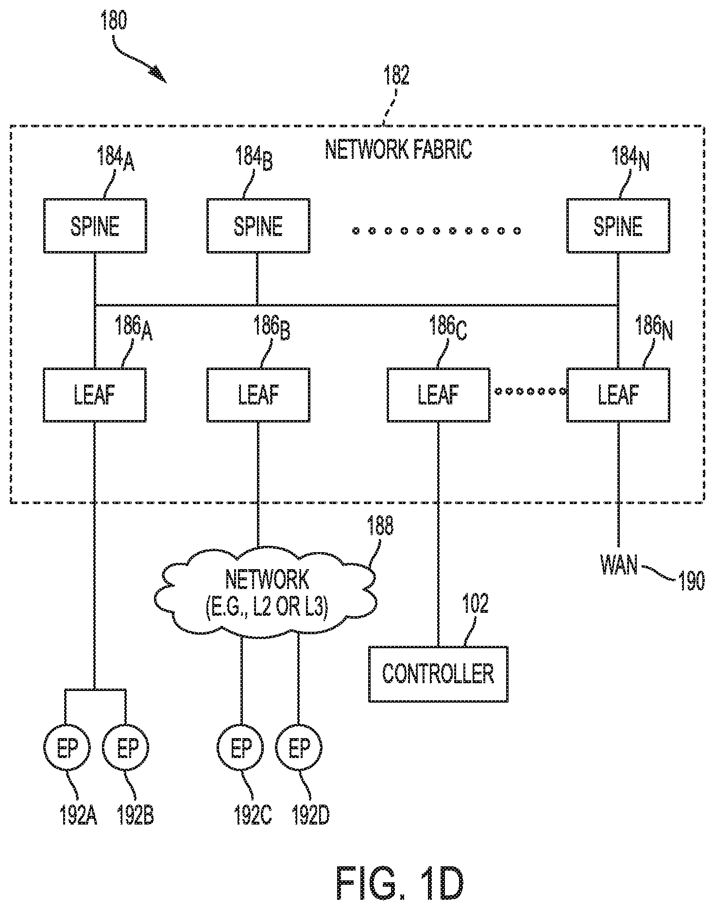
FIG. 1D illustrates a schematic block diagram of an example network architecture 180. In some cases, the architecture 180 can include a data center, which can support and/or host the cloud 132. Moreover, the architecture 180 includes a network fabric 182 with spines 184A, 184B, . . . , 184N (collectively "184") connected to leafs 186A, 186B, 186C, . . . , 186N (collectively "186") in the network fabric 182. Spines 184 and leafs 186 can be Layer 2 and/or Layer 3 devices, such as switches or routers. For the sake of clarity, they will be referenced herein as spine switches 184 and leaf switches 186.
Spine switches 184 connect to leaf switches 186 in the fabric 182. Leaf switches 186 can include access ports (or non-fabric ports) and fabric ports. Fabric ports can provide uplinks to the spine switches 182, while access ports can provide connectivity for devices, hosts, endpoints, VMs, or external networks to the fabric 182.
Leaf switches 186 can reside at the boundary between the fabric 182 and the tenant or customer space. The leaf switches 186 can route and/or bridge the tenant packets and apply network policies. In some cases, a leaf switch can perform one or more additional functions, such as implementing a mapping cache, sending packets to the proxy function when there is a miss in the cache, encapsulate packets, enforce ingress or egress policies, etc.
Moreover, the leaf switches 186 can contain virtual switching and/or tunneling functionalities, such as a virtual tunnel endpoint (VTEP) function. Thus, leaf switches 186 can connect the fabric 182 to an overlay (e.g., VXLAN network).
Network connectivity in the fabric 182 can flow through the leaf switches 186. The leaf switches 186 can provide servers, resources, endpoints, external networks, containers, or VMs access to the fabric 182, and can connect the leaf switches 186 to each other. The leaf switches 186 can connect applications and/or endpoint groups ("EPGs") to other resources inside or outside of the fabric 182 as well as any external networks.
Endpoints 192A-D (collectively "192") can connect to the fabric 182 via leaf switches 186. For example, endpoints 192A and 192B can connect directly to leaf switch 186A, which can connect endpoints 192A and 192B to the fabric 182 and/or any other of the leaf switches 186. Similarly, controller 102 (which can be the same as controller 102 described above with reference to FIG. 1A) can connect directly to leaf switch 186C, which can connect controller 102 to the fabric 182 and/or any other of the leaf switches 186. On the other hand, endpoints 192C and 192D can connect to leaf switch 186A and 186B via network 188. Moreover, the wide area network (WAN) 190 can connect to the leaf switches 186N.
Endpoints 192 can include any communication device or resource, such as a computer, a server, a cluster, a switch, a container, a VM, a virtual application, etc. In some cases, the endpoints 192 can include a server or switch configured with a virtual tunnel endpoint functionality which connects an overlay network with the fabric 182. For example, in some cases, the endpoints 192 can represent hosts (e.g., servers) with virtual tunnel endpoint capabilities, and running virtual environments (e.g., hypervisor, virtual machine(s), containers, etc.). An overlay network associated with the endpoints 192 can host physical devices, such as servers; applications; EPGs; virtual segments; virtual workloads; etc. Likewise, endpoints 192 can also host virtual workloads and applications, which can connect with the fabric 182 or any other device or network, including an external network.
The disclosure now turns to FIGS. 2 and 3, which illustrate example network devices and computing devices, such as switches, routers, load balancers, client devices, and so forth.
FIG. 2 illustrates an example network device suitable for performing switching, routing, load balancing, and other networking operations, according to an aspect of the present disclosure. In one example, network device 200 can be controller 102 and/or any one of components 122 of FIG. 1A. Network device 200 includes a central processing unit (CPU) 204, interfaces 202, and a bus 210 (e.g., a PCI bus). When acting under the control of appropriate software or firmware, CPU 204 is responsible for executing packet management, error detection, and/or routing functions. CPU 204 preferably accomplishes all these functions under the control of software including an operating system and any appropriate applications software. CPU 204 may include one or more processors 208, such as a processor from the INTEL X86 family of microprocessors. In some cases, processor 208 can be specially designed hardware for controlling the operations of network device 200. In some cases, a memory 206 (e.g., non-volatile RAM, ROM, etc.) also forms part of CPU 204. However, there are many different ways in which memory could be coupled to the system.
Interfaces 202 are typically provided as modular interface cards (sometimes referred to as "line cards"). Generally, they control the sending and receiving of data packets over the network and sometimes support other peripherals used with network device 200. Among the interfaces that may be provided are Ethernet interfaces, frame relay interfaces, cable interfaces, DSL interfaces, token ring interfaces, and the like. In addition, various very high-speed interfaces may be provided such as fast token ring interfaces, wireless interfaces, Ethernet interfaces, Gigabit Ethernet interfaces, ATM interfaces, HSSI interfaces, POS interfaces, FDDI interfaces, WIFI interfaces, 3G/4G/5G cellular interfaces, CAN BUS, LoRA, and the like. Generally, these interfaces may include ports appropriate for communication with the appropriate media. In some cases, they may also include an independent processor and, in some instances, volatile RAM. The independent processors may control such communications intensive tasks as packet switching, media control, signal processing, crypto processing, and management. By providing separate processors for the communications intensive tasks, these interfaces allow the master microprocessor 204 to efficiently perform routing computations, network diagnostics, security functions, etc.
Although the system shown in FIG. 2 is one specific network device of the present invention, it is by no means the only network device architecture on which the present invention can be implemented. For example, an architecture having a single processor that handles communications as well as routing computations, etc., is often used. Further, other types of interfaces and media could also be used with network device 200.
Regardless of the network device's configuration, it may employ one or more memories or memory modules (including memory 206) configured to store program instructions for the general-purpose network operations and mechanisms for roaming, route optimization and routing functions described herein. The program instructions may control the operation of an operating system and/or one or more applications, for example. The memory or memories may also be configured to store tables such as mobility binding, registration, and association tables, etc. Memory 206 could also hold various software containers and virtualized execution environments and data.
Network device 200 can also include an application-specific integrated circuit (ASIC), Which can be configured to perform routing and/or switching operations. The ASIC can communicate with other components in network device 200 via bus 210, to exchange data and signals and coordinate various types of operations by network device 200, such as routing, switching, and/or data storage operations, for example.
FIG. 3 illustrates a computing system architecture, according to an aspect of the present disclosure. As shown in FIG. 3, components of system 300 are in electrical communication with each other using a connection 305, such as a bus. Exemplary system 300 includes a processing unit (CPU or processor) 310 and a system connection 305 that couples various system components including system memory 315, such as read only memory (ROM) 320 and random access memory (RAM) 325, to processor 710. System 300 can include a cache of high-speed memory connected directly with, in close proximity to, or integrated as part of the processor 310. System 300 can copy data from memory 315 and/or storage device 330 to cache 312 for quick access by processor 310. In this way, the cache can provide a performance boost that avoids processor 310 delays while waiting for data. These and other modules can control or be configured to control the processor 310 to perform various actions. Other system memory 315 may be available for use as well. Memory 315 can include multiple different types of memory with different performance characteristics. Processor 310 can include any general purpose processor and a hardware or software service, such as Service 1 332, Service 2 334, and Service 3 336 stored in storage device 330, configured to control processor 310 as well as a special-purpose processor where software instructions are incorporated into the actual processor design. Processor 310 may be a completely self-contained computing system, containing multiple cores or processors, a bus, memory controller, cache, etc. A multi-core processor may be symmetric or asymmetric.
To enable user interaction with the computing device 300, an input device 345 can represent any number of input mechanisms, such as a microphone for speech, a touch-sensitive screen for gesture or graphical input, keyboard, mouse, motion input, speech and so forth. An output device 335 can also be one or more of a number of output mechanisms known to those of skill in the art. In some instances, multimodal systems can enable a user to provide multiple types of input to communicate with computing device 300. The communications interface 340 can generally govern and manage the user input and system output. There is no restriction on operating on any particular hardware arrangement and therefore the basic features here may easily be substituted for improved hardware or firmware arrangements as they are developed.
Storage device 330 is a non-volatile memory and can be a hard disk or other types of computer readable media which can store data that are accessible by a computer, such as magnetic cassettes, flash memory cards, solid state memory devices, digital versatile disks, cartridges, random access memories (RAMS) 325, read only memory (ROM) 320, and hybrids thereof.
The storage device 330 can include services 332, 334, 336 for controlling the processor 310. Other hardware or software modules are contemplated. The storage device 330 can be connected to the system connection 305. In one aspect, a hardware module that performs a particular function can include the software component stored in a computer-readable medium in connection with the necessary hardware components, such as the processor 310, connection 305, output device 335, and so forth, to carry out the function.
FIG. 4 illustrates an example system of service function chaining environment, according to an aspect of the present disclosure.
According to FIG. 4, a system 400 includes a physical host 402 (which can be any one of servers 134, VMs 136, Software platforms 138, Applications 140, containers 142 and/or infrastructure nodes 144 shown in FIG. 1B) and a physical host 450 (which can be any one of servers 134, VMs 136, Software platforms 138, Applications 140, containers 142 and/or infrastructure nodes 144 shown in FIG. 1B). While FIG. 4 illustrates two physical hosts, the number of physical hosts of system 400 can be more or less. System 400 can include only physical host 402 or more than two physical hosts 402 and 450 shown in FIG. 4.
Physical host 402 has a physical port 404 through which real time network traffic (e.g., data packets, OAM probes, etc.) arrive at the physical host 402, via cloud 132, to be processed. Physical host 402 can have Contiv HostAgent 406. Contiv HostAgent 406 (hereinafter Contiv 404 or agent 404) is implemented via one or more processors of physical host 402 for delivering/deploying and managing micro-services on physical host 402. As is known, Contiv 406 is a network abstraction layer for microservices, with examples of microservices being service functions (SF) (which can also be referred to as Containers) 408, 410, 412 and 414.
Contiv 406, as shown in FIG. 4, can have one or more virtual input/output ports to and from containers 408-414, such as vport1 to container 408, vport11 to container 410, vport12 to container 412, vport13 to container 414. Each of containers 408-414 can have an associated virtual port (eth0) for exchange of network traffic (data packets) with Contiv 406 via corresponding vport of Contiv 404. In one non-limiting example of containers 408-414, as shown in FIG. 4, container 408 is a service function forwarder (SFF) that implements policies for forwarding/load balancing network traffic between containers that provide a particular service function. Hereinafter, container 408 is used as an example of a proxy for obtaining path specific telemetry data and can also be referred to as a controller.
In one example, container 408 can have table 416 associated therewith, which can also be referred to as a SFF network service header forwarding table. In one example, upon receiving a data packet, container 408 compares information included in a network service header (NSH) of the received packet/probe to information available in table 416 (e.g., information provided under the Header Field column in Table 416 and the corresponding information under the Action column in Table 416) identify containers amongst which received data packets are to be load balanced. An example of information under the Header Field column, shown in FIG. 4, is "SFP.ID=100;SI=254". "SFP.ID" can be a service function path ID (service path ID) that indicates which service function (container) is the traffic to be steered to while "SI" can a service index that specifies the hop(s) within a service function path. Furthermore, information under the Action column can identify the next hope, which in the example table 416 can be load balancing between service functions (containers 410, 412, 414 and 452).
As mentioned above, system 400 also includes physical host 450 having a corresponding container 452 and a corresponding Contiv HostAgent 454. Operation of Contiv HostAgent 454 (which can hereinafter be referred to as Contiv 454) is the same as Contiv 406 described above. In one example, containers 410-414 and container 452 together form a cluster of containers that provide a specific type of function (e.g., a firewall service, thus making the duster of containers 410-414 and 452 a firewall cluster, as shown in FIG. 4).
Each of physical hosts 402 and 450 have corresponding ports (dpdk0, dpdk1), through which information and data packets are exchanged between physical hosts 402 and 450. Physical hosts 402 and 450 may be connected via any known or to be developed wired and/or wireless links 460 and 462, as shown in FIG. 4.
Contiv 404 also has a monitoring agent 418 (examples of which are Coscale agent, New Relic agent, etc.), which as will be described below, are used to collect requested micro-service telemetry data. Similarly, Contiv 454 has a monitoring agent 456 (examples of which are Coscale agent, New Relic agent, etc.), which as will be described below, are used to collect requested micro-service telemetry data.
Hereinafter, a process of using an overlay termination endpoint as a proxy for obtaining telemetry data/flow statistics on containers (service functions) running on a host will be described.
FIG. 5 describes a method of obtaining telemetry data on containers, according to an aspect of the present disclosure. FIG. 5 is described with reference to FIG. 4 and is from the perspective of container 408 (SFF 408) of Fla 4. However, it will be understood that one or more processors that execute computer-readable instructions to function as container 408 perform the process of FIG. 5.
At S500, container 408 (which can also be referred to as a controller or an overlay termination endpoint or simply endpoint 408) receives an OAM probe from an initiator. The initiator can be a network operator accessing system 400 via a corresponding device, one or more clients endpoints 146 of FIG. 1B, etc. The OAM probe arrives at container 408 via cloud 132 and at physical port 404. The OAM probe can also be referred to as a probe for flow statistics. The OAM probe can be for various statistics/telemetry data for a specific data path (flow) to and from a service function (container). Examples of various path statistics/telemetry data include, but are not limited to, number of packets on the service path, number of bytes, rates for performance management such as packets per second, number of errors, etc. In one example, the initiator triggers a service function chaining trace (SFC trace), as known to those having ordinary skills in the art. Furthermore, the OAM probe includes identifying information of the specific data path/flow (flow identification information. Examples of flow identification information include, but are not limited to, a flow ID, a flow label, entropy details (e.g., load balancing as will be further described below with reference to FIG. 6), etc.
In one example, the OAM probe received at container 408 has a format (which will be further described below with respect to FIG. 6). The OAM probe includes a payload. At S502, container 408 extracts (obtains) the flow identification information from the payload together with entropy details of the OAM probe received at S500. Based on the obtained flow identification information and the entropy label, container 408 can determine a container that is the destination (destination container) of the corresponding data path (flow) and subsequently the virtual port (vport) via which Contiv 406 sends frame and data packets to the destination container for processing.
At S503, container 408 generates a query for the flow statistics based on the entropy label and the extracted flow identification information. In one example and as part of generating the query, container 408 includes (sets) a source MAC address (SMAC) (address of container 408), a destination MAC address (DMAC) (address of the destination container) for the flow and the entropy label details in a YANG query to be sent to Contiv 406. Yang is an example of a protocol/programming language used to generate the query. However, other known or to be developed protocols/programming languages can also be used.
At S504, container 408 determines whether the destination container is hosted/instantiated on the same physical host as container 408 (e.g., host 402) or a different host (e.g., host 450). In one example, if the destination container is one of containers 410, 412 and 414, container 408 determines that the destination container is hosted on the same physical host 402 as container 408. However, if the destination container is container 452 hosted on physical host 450, container 408 determines that the destination container is hosted on a different physical host.
If at S504, container 408 determines that the destination container is hosted/instantiated on the same physical host as container 408, then at S506, container 408 sends the generated query to Contiv 406 (agent).
In one example, container 408 sends the query to Contiv 406 on south bound APIs such as "eth0" and vport1 shown in FIG. 4.
Upon receiving the query, Contiv 406 uses a local monitoring agent associated therewith (e.g., agent 418 associated with Contiv 406) to obtain the requested flow statistics.
Thereafter, at S508, container 408 receives a reply (response packet) back from Contiv 406 that includes the requested flow statistics. At S510, container 408 includes the reply in a data packet (generates a response packet) to be sent back to initiator from which the OAM probe is received at S500. At S511, the generated response data packet is sent back to the initiator via physical port 404 and cloud 132.
Referring back to S504, if at S504, container 408 determines that the destination container is not hosted/instantiate on the same physical host as container 408, at S512, container 408 modifies a query to include the IP address of the physical host (e.g., physical host 450) that hosts the destination container.
Then at S514, container 408 sends the modified query for the flow statistics to Contiv 454 (hosted on the different physical host 450). In one example and as part of the query, container 408 includes (sets) a source MAC address (SMAC) and a destination MAC address (DMAC) and include the entropy details obtained as part of the flow identification information in a YANG query to be sent to Contiv 454.
In one example, container 408 sends the query to Contiv 454 on south bound APIs such as "eth0" and vport1 shown in FIG. 4.
Upon receiving the query, Contiv 454 uses a local monitoring agent associated therewith (e.g., agent 456 associated with Contiv 454) to obtain the requested flow statistics.
Thereafter, the process returns to S508, where container 408 receives a reply back from Contiv 454 that includes the requested flow statistics. This is then followed by the processes at S510 and S511, as described above.
FIG. 6 illustrates an example of the process of FIG. 5, according an aspect of the present disclosure. In FIG. 6, elements that have the same numerical reference number as those shown in FIG. 4, operate in the same manner as described with reference to FIG. 4 and thus are not described again for sake of brevity.
As shown in FIG. 6, OAM probe 605 of S500 is received at Contiv 408 via cloud 132 and physical port 404 along path 600. OAM probe 605 has a format, mentioned above. According to example format, OAM probe 605 has payload 607, entropy details 609 (e.g., load balancing "xyz" shown in FIG. 6 can be any action such as load balancing), SFC trace 611, network service header (NSH) 613 and IP header 615. In one example, instead of NSH 613, OAM probe can have SRv6 header 613, EVPN header 613 and/or IPv6 header 613.
Using information provided as part of OAM probe 605, container 408 determines how to manage OAM probe 605. For example and as described above, container 408 extracts entropy details 609 from OAM probe 605 and includes the same in the query sent to Contiv 406 or Contiv 454. Furthermore, by detecting the SFC trace 611, container 408 determines that the received packet is an OAM probe, which triggers container 408 to extract the entropy and flow identification information from payload 605 and initiate the process of obtaining flow statistics.
FIG. 7 illustrates an example of the process of FIG. 5, according an aspect of the present disclosure. In FIG. 7, elements that have the same numerical reference number as those shown in FIG. 4 and FIG. 6, operate in the same manner as described with reference to FIG. 4 and FIG. 6 and thus are not described again for sake of brevity.
As shown in FIG. 7, after receiving OAM probe 605 at S500 and extracting entropy details and other flow identification information, container 408 generates query 700, which can be a YANG query. A pseudo example of such query 700 indicates a request for flow statistics associated with a port (a vport) having a starting MAC address of container 408 (SFF) and destination MAC address (FwCluster Addr such as vport 11, vport 12, vport 13 and/or vport 21).
One advantage of using an overlay termination endpoint such as container 408 as a proxy for obtaining flow statistics of service function paths, as described with reference to FIGS. 4-7 above, include elimination of the need for micro-services enabled on each container to learn, understand and process overlay OAM probe packets. Another advantage is that using such proxy allows for inter-layer correlation for container performance in overlay data center deployments.
For clarity of explanation, in some instances the present technology may be presented as including individual functional blocks including functional blocks comprising devices, device components, steps or routines in a method embodied in software, or combinations of hardware and software.
In some embodiments the computer-readable storage devices, mediums, and memories can include a cable or wireless signal containing a bit stream and the like. However, when mentioned, non-transitory computer-readable storage media expressly exclude media such as energy, carrier signals, electromagnetic waves, and signals per se.
Methods according to the above-described examples can be implemented using computer-executable instructions that are stored or otherwise available from computer readable media. Such instructions can comprise, for example, instructions and data which cause or otherwise configure a general purpose computer, special purpose computer, or special purpose processing device to perform a certain function or group of functions. Portions of computer resources used can be accessible over a network. The computer executable instructions may be, for example, binaries, intermediate format instructions such as assembly language, firmware, or source code. Examples of computer-readable media that may be used to store instructions, information used, and/or information created during methods according to described examples include magnetic or optical disks, flash memory, USB devices provided with non-volatile memory, networked storage devices, and so on.
Devices implementing methods according to these disclosures can comprise hardware, firmware and/or software, and can take any of a variety of form factors. Typical examples of such form factors include laptops, smart phones, small form factor personal computers, personal digital assistants, rackmount devices, standalone devices, and so on. Functionality described herein also can be embodied in peripherals or add-in cards. Such functionality can also be implemented on a circuit board among different chips or different processes executing in a single device, by way of further example.
The instructions, media for conveying such instructions, computing resources for executing them, and other structures for supporting such computing resources are means for providing the functions described in these disclosures.
Although a variety of examples and other information was used to explain aspects within the scope of the appended claims, no limitation of the claims should be implied based on particular features or arrangements in such examples, as one of ordinary skill would be able to use these examples to derive a wide variety of implementations. Further and although some subject matter may have been described in language specific to examples of structural features and/or method steps, it is to be understood that the subject matter defined in the appended claims is not necessarily limited to these described features or acts. For example, such functionality can be distributed differently or performed in components other than those identified herein. Rather, the described features and steps are disclosed as examples of components of systems and methods within the scope of the appended claims.
Claim language reciting "at least one of" refers to at least one of a set and indicates that one member of the set or multiple members of the set satisfy the claim. For example, claim language reciting "at least one of A and B" means A, B, or A and B.
* * * * *
References
-
tools.ietf.org/pdf/draft-ietf-dots-requirements-01.pdf
-
-
en.wikipedia.org/w/index.php?title=CEA-708&oldid=523143431
-
cloud.google.com/functions/docs/concepts/overview
-
-
-
developersidgerun.conn/wiki/index.php/GStreanner_and_in-band_nnetadata
-
erg.abdn.ac.uk/future-net/digital-video/mpeg2-trans.html
-
-
usenix.org/system/files/conference/hotcloud16/hotcloud16_hendrickson.pdf
-
developer.ibm.com/open/2016/02/22/openwhisk-a-quick-tech-preview
-
-
techcrunch.com/2016/08/03/what-real-cloud-native-apps-will-look-like
D00000
D00001
D00002
D00003
D00004
D00005
D00006
D00007
D00008
D00009
D00010
XML
uspto.report is an independent third-party trademark research tool that is not affiliated, endorsed, or sponsored by the United States Patent and Trademark Office (USPTO) or any other governmental organization. The information provided by uspto.report is based on publicly available data at the time of writing and is intended for informational purposes only.
While we strive to provide accurate and up-to-date information, we do not guarantee the accuracy, completeness, reliability, or suitability of the information displayed on this site. The use of this site is at your own risk. Any reliance you place on such information is therefore strictly at your own risk.
All official trademark data, including owner information, should be verified by visiting the official USPTO website at www.uspto.gov. This site is not intended to replace professional legal advice and should not be used as a substitute for consulting with a legal professional who is knowledgeable about trademark law.