Magnetic tape having characterized magnetic layer and back coating layer
Kasada J
U.S. patent number 10,529,368 [Application Number 15/690,400] was granted by the patent office on 2020-01-07 for magnetic tape having characterized magnetic layer and back coating layer. This patent grant is currently assigned to FUJIFILM Corporation. The grantee listed for this patent is FUJIFILM Corporation. Invention is credited to Norihito Kasada.
View All Diagrams
| United States Patent | 10,529,368 |
| Kasada | January 7, 2020 |
Magnetic tape having characterized magnetic layer and back coating layer
Abstract
A magnetic tape includes: a non-magnetic support; a magnetic layer on one surface side of the non-magnetic support; and a back coating layer on the other surface side. The center line average surface roughness Ra measured regarding the surface of the magnetic layer is 1.0 nm to 1.8 nm. The magnetic layer includes ferromagnetic hexagonal ferrite powder and non-magnetic powder. The tilt cos .theta. of the ferromagnetic hexagonal ferrite powder with respect to a surface of the magnetic layer acquired by cross section observation performed using a scanning transmission electron microscope is 0.85 to 1.00. Further, the logarithmic decrement acquired by a pendulum viscoelasticity test performed regarding the surface of the back coating layer is less than or equal to 0.060.
| Inventors: | Kasada; Norihito (Minami-ashigara, JP) | ||||||||||
|---|---|---|---|---|---|---|---|---|---|---|---|
| Applicant: |
|
||||||||||
| Assignee: | FUJIFILM Corporation (Tokyo,
JP) |
||||||||||
| Family ID: | 61243235 | ||||||||||
| Appl. No.: | 15/690,400 | ||||||||||
| Filed: | August 30, 2017 |
Prior Publication Data
| Document Identifier | Publication Date | |
|---|---|---|
| US 20180061447 A1 | Mar 1, 2018 | |
Foreign Application Priority Data
| Aug 31, 2016 [JP] | 2016-169871 | |||
| Current U.S. Class: | 1/1 |
| Current CPC Class: | G11B 5/78 (20130101); G11B 5/70 (20130101); G11B 2220/93 (20130101) |
| Current International Class: | G11B 5/70 (20060101); G11B 5/78 (20060101) |
References Cited [Referenced By]
U.S. Patent Documents
| 3966686 | June 1976 | Asakura et al. |
| 4112187 | September 1978 | Asakura et al. |
| 4425404 | January 1984 | Suzuki et al. |
| 4693930 | September 1987 | Kuo et al. |
| 4746569 | May 1988 | Takahashi |
| 4825317 | April 1989 | Rausch |
| 5242752 | September 1993 | Isobe et al. |
| 5419938 | May 1995 | Kagotani et al. |
| 5445881 | September 1995 | Irie |
| 5474814 | December 1995 | Komatsu |
| 5496607 | March 1996 | Inaba et al. |
| 5540957 | July 1996 | Ueda et al. |
| 5585032 | December 1996 | Nakata et al. |
| 5645917 | July 1997 | Ejiri et al. |
| 5689384 | November 1997 | Albrecht et al. |
| 5728454 | March 1998 | Inaba et al. |
| 5786074 | June 1998 | Soui |
| 5827600 | October 1998 | Ejiri et al. |
| 6099957 | August 2000 | Yamamoto et al. |
| 6183606 | February 2001 | Kuo et al. |
| 6207252 | March 2001 | Shimomura |
| 6228461 | May 2001 | Sueki et al. |
| 6254964 | July 2001 | Saito et al. |
| 6261647 | July 2001 | Komatsu |
| 6268043 | July 2001 | Koizumi et al. |
| 6496328 | December 2002 | Dugas |
| 6579826 | June 2003 | Furuya et al. |
| 6649256 | November 2003 | Buczek |
| 6686022 | February 2004 | Takano et al. |
| 6770359 | August 2004 | Masaki |
| 6791803 | September 2004 | Saito et al. |
| 6835461 | December 2004 | Yamagata et al. |
| 6893746 | May 2005 | Kirino et al. |
| 6921592 | July 2005 | Tani et al. |
| 6939606 | September 2005 | Hashimoto et al. |
| 6950269 | September 2005 | Johnson |
| 6994925 | February 2006 | Masaki |
| 7014927 | March 2006 | Sueki et al. |
| 7029726 | April 2006 | Chen et al. |
| 7153366 | December 2006 | Chen et al. |
| 7255908 | August 2007 | Ishikawa et al. |
| 7511907 | March 2009 | Dugas et al. |
| 7515383 | April 2009 | Saito et al. |
| 7803471 | September 2010 | Ota et al. |
| 7839599 | November 2010 | Bui et al. |
| 8000057 | August 2011 | Bui et al. |
| 8524108 | September 2013 | Hattori |
| 8535817 | September 2013 | Imaoka |
| 8576510 | November 2013 | Cherubini et al. |
| 8681451 | March 2014 | Harasawa et al. |
| 9105294 | August 2015 | Jensen et al. |
| 9311946 | April 2016 | Tanaka et al. |
| 9495985 | November 2016 | Biskeborn et al. |
| 9530444 | December 2016 | Kasada |
| 9542967 | January 2017 | Sekiguchi et al. |
| 9564161 | February 2017 | Cherubini et al. |
| 9601146 | March 2017 | Kasada et al. |
| 9704425 | July 2017 | Zhang et al. |
| 9704525 | July 2017 | Kasada |
| 9704527 | July 2017 | Kasada |
| 9711174 | July 2017 | Kasada |
| 9721605 | August 2017 | Oyanagi |
| 9721606 | August 2017 | Kasada |
| 9721607 | August 2017 | Tada et al. |
| 9748026 | August 2017 | Shirata |
| 9773519 | September 2017 | Kasada et al. |
| 9779772 | October 2017 | Kasada et al. |
| 9837104 | December 2017 | Biskeborn |
| 9837116 | December 2017 | Ozawa |
| 9959894 | May 2018 | Omura |
| 9972351 | May 2018 | Kaneko et al. |
| 9978414 | May 2018 | Kaneko |
| 9984710 | May 2018 | Kasada |
| 9984712 | May 2018 | Ozawa |
| 9984716 | May 2018 | Kaneko |
| 10008230 | June 2018 | Ozawa et al. |
| 10026430 | July 2018 | Kasada et al. |
| 10026433 | July 2018 | Kasada et al. |
| 10026434 | July 2018 | Oyanagi |
| 10026435 | July 2018 | Kasada et al. |
| 10062403 | August 2018 | Kasada et al. |
| 10074393 | September 2018 | Kaneko |
| 10134433 | November 2018 | Kasada et al. |
| 10170144 | January 2019 | Ozawa et al. |
| 2001/0038928 | November 2001 | Nakamigawa |
| 2001/0053458 | December 2001 | Suzuki et al. |
| 2002/0072472 | July 2002 | Furuya et al. |
| 2002/0122339 | September 2002 | Takano et al. |
| 2003/0059649 | March 2003 | Saliba et al. |
| 2003/0091866 | May 2003 | Ejiri et al. |
| 2003/0124386 | July 2003 | Masaki |
| 2003/0170498 | September 2003 | Inoue |
| 2003/0228493 | December 2003 | Doushita et al. |
| 2004/0018388 | January 2004 | Kitamura et al. |
| 2004/0053074 | March 2004 | Jingu et al. |
| 2004/0197605 | October 2004 | Seki et al. |
| 2004/0213948 | October 2004 | Saito et al. |
| 2004/0218304 | November 2004 | Goker et al. |
| 2004/0265643 | December 2004 | Ejiri |
| 2005/0057838 | March 2005 | Ohtsu |
| 2005/0153170 | July 2005 | Inoue et al. |
| 2005/0196645 | September 2005 | Doi et al. |
| 2005/0260456 | November 2005 | Hanai et al. |
| 2005/0260459 | November 2005 | Hanai et al. |
| 2005/0264935 | December 2005 | Sueki et al. |
| 2006/0008681 | January 2006 | Hashimoto et al. |
| 2006/0035114 | February 2006 | Kuse |
| 2006/0056095 | March 2006 | Saitou |
| 2006/0068232 | March 2006 | Mikamo et al. |
| 2006/0187589 | August 2006 | Harasawa et al. |
| 2006/0232883 | October 2006 | Biskeborn et al. |
| 2007/0009769 | January 2007 | Kanazawa |
| 2007/0020489 | January 2007 | Yamazaki et al. |
| 2007/0020490 | January 2007 | Harasawa et al. |
| 2007/0224456 | September 2007 | Murao et al. |
| 2007/0230054 | October 2007 | Takeda et al. |
| 2007/0231606 | October 2007 | Hanai |
| 2008/0057351 | March 2008 | Meguro et al. |
| 2008/0144211 | June 2008 | Weber et al. |
| 2008/0152956 | June 2008 | Murayama et al. |
| 2008/0174897 | July 2008 | Bates et al. |
| 2008/0297950 | December 2008 | Noguchi et al. |
| 2008/0311308 | December 2008 | Lee et al. |
| 2009/0027812 | January 2009 | Noguchi et al. |
| 2009/0087689 | April 2009 | Doushita et al. |
| 2009/0161249 | June 2009 | Takayama et al. |
| 2009/0162701 | June 2009 | Jensen et al. |
| 2010/0000966 | January 2010 | Kamata et al. |
| 2010/0035086 | February 2010 | Inoue et al. |
| 2010/0035088 | February 2010 | Inoue |
| 2010/0053810 | March 2010 | Biskeborn et al. |
| 2010/0073816 | March 2010 | Komori et al. |
| 2010/0081011 | April 2010 | Nakamura |
| 2010/0134929 | June 2010 | Ito |
| 2010/0227201 | September 2010 | Sasaki et al. |
| 2010/0246073 | September 2010 | Katayama |
| 2011/0003241 | January 2011 | Kaneko |
| 2011/0051280 | March 2011 | Karp et al. |
| 2011/0052908 | March 2011 | Imaoka |
| 2011/0077902 | March 2011 | Awezec et al. |
| 2011/0151281 | June 2011 | Inoue |
| 2011/0244272 | October 2011 | Suzuki et al. |
| 2012/0045664 | February 2012 | Tanaka |
| 2012/0152891 | June 2012 | Brown et al. |
| 2012/0177951 | July 2012 | Yamazaki et al. |
| 2012/0183811 | July 2012 | Hattori et al. |
| 2012/0196156 | August 2012 | Suzuki |
| 2012/0243120 | September 2012 | Harasawa et al. |
| 2012/0244387 | September 2012 | Mori et al. |
| 2012/0251845 | October 2012 | Wang et al. |
| 2013/0029183 | January 2013 | Omura et al. |
| 2013/0084470 | April 2013 | Hattori et al. |
| 2013/0088794 | April 2013 | Cherubini et al. |
| 2013/0256584 | October 2013 | Yamazaki |
| 2013/0260179 | October 2013 | Kasada et al. |
| 2013/0279040 | October 2013 | Cideciyan |
| 2013/0286510 | October 2013 | Rothermel et al. |
| 2014/0011055 | January 2014 | Suzuki et al. |
| 2014/0130067 | May 2014 | Madison et al. |
| 2014/0139944 | May 2014 | Johnson et al. |
| 2014/0272474 | September 2014 | Kasada |
| 2014/0295214 | October 2014 | Tada et al. |
| 2014/0342189 | November 2014 | Tachibana et al. |
| 2014/0366990 | December 2014 | Lai et al. |
| 2014/0374645 | December 2014 | Kikuchi et al. |
| 2015/0043101 | February 2015 | Biskeborn et al. |
| 2015/0098149 | April 2015 | Bates et al. |
| 2015/0111066 | April 2015 | Terakawa et al. |
| 2015/0123026 | May 2015 | Masada et al. |
| 2015/0302879 | October 2015 | Holmberg et al. |
| 2015/0380036 | December 2015 | Kasada et al. |
| 2016/0061447 | March 2016 | Kobayashi |
| 2016/0064025 | March 2016 | Kurokawa et al. |
| 2016/0092315 | March 2016 | Ashida |
| 2016/0093321 | March 2016 | Aoshima et al. |
| 2016/0093322 | March 2016 | Kasada et al. |
| 2016/0093323 | March 2016 | Omura |
| 2016/0180875 | June 2016 | Tanaka et al. |
| 2016/0189739 | June 2016 | Kasada et al. |
| 2016/0189740 | June 2016 | Oyanagi et al. |
| 2016/0247530 | August 2016 | Kasada |
| 2016/0260449 | September 2016 | Ahmad et al. |
| 2016/0276076 | September 2016 | Kasada |
| 2017/0032812 | February 2017 | Kasada |
| 2017/0053669 | February 2017 | Kasada |
| 2017/0053670 | February 2017 | Oyanagi et al. |
| 2017/0053671 | February 2017 | Kasada et al. |
| 2017/0058227 | March 2017 | Kondo et al. |
| 2017/0092315 | March 2017 | Ozawa et al. |
| 2017/0130156 | May 2017 | Kondo et al. |
| 2017/0178675 | June 2017 | Kasada |
| 2017/0178676 | June 2017 | Kasada |
| 2017/0178677 | June 2017 | Kasada |
| 2017/0186456 | June 2017 | Tada et al. |
| 2017/0186460 | June 2017 | Kasada et al. |
| 2017/0221513 | August 2017 | Hiroi et al. |
| 2017/0221516 | August 2017 | Oyanagi |
| 2017/0221517 | August 2017 | Ozawa et al. |
| 2017/0249963 | August 2017 | Oyanagi et al. |
| 2017/0249964 | August 2017 | Kasada et al. |
| 2017/0249965 | August 2017 | Kurokawa et al. |
| 2017/0249966 | August 2017 | Tachibana et al. |
| 2017/0287517 | October 2017 | Hosoya et al. |
| 2017/0355022 | December 2017 | Kaneko |
| 2017/0358318 | December 2017 | Kasada |
| 2017/0372726 | December 2017 | Kasada |
| 2017/0372727 | December 2017 | Kasada et al. |
| 2017/0372736 | December 2017 | Kaneko |
| 2017/0372737 | December 2017 | Oyanagi et al. |
| 2017/0372738 | December 2017 | Kasada |
| 2017/0372739 | December 2017 | Ozawa |
| 2017/0372740 | December 2017 | Ozawa et al. |
| 2017/0372741 | December 2017 | Kurokawa et al. |
| 2017/0372742 | December 2017 | Kaneko |
| 2017/0372743 | December 2017 | Kasada |
| 2017/0372744 | December 2017 | Ozawa et al. |
| 2018/0061446 | March 2018 | Kasada |
| 2018/0061447 | March 2018 | Kasada |
| 2018/0082710 | March 2018 | Tada et al. |
| 2018/0137887 | May 2018 | Sekiguchi et al. |
| 2018/0182417 | June 2018 | Kaneko et al. |
| 2018/0182422 | June 2018 | Kawakami et al. |
| 2018/0182425 | June 2018 | Kasada et al. |
| 2018/0182426 | June 2018 | Ozawa et al. |
| 2018/0182427 | June 2018 | Kasada |
| 2018/0182429 | June 2018 | Kasada et al. |
| 2018/0182430 | June 2018 | Ozawa et al. |
| 2018/0182428 | July 2018 | Kasada et al. |
| 2018/0240475 | August 2018 | Kasada |
| 2018/0240476 | August 2018 | Kasada et al. |
| 2018/0240478 | August 2018 | Kasada et al. |
| 2018/0240479 | August 2018 | Kasada et al. |
| 2018/0240481 | August 2018 | Kasada et al. |
| 2018/0240488 | August 2018 | Kasada |
| 2018/0240489 | August 2018 | Kasada et al. |
| 2018/0240490 | August 2018 | Kurokawa et al. |
| 2018/0240491 | August 2018 | Ozawa et al. |
| 2018/0240492 | August 2018 | Kasada |
| 2018/0240493 | August 2018 | Tada et al. |
| 2018/0240494 | August 2018 | Kurokawa |
| 2018/0240495 | August 2018 | Kasada |
| 2018/0286439 | October 2018 | Ozawa et al. |
| 2018/0286442 | October 2018 | Ozawa et al. |
| 2018/0286443 | October 2018 | Ozawa et al. |
| 2018/0286444 | October 2018 | Kasada et al. |
| 2018/0286446 | October 2018 | Ozawa et al. |
| 2018/0286447 | October 2018 | Ozawa et al. |
| 2018/0286448 | October 2018 | Ozawa et al. |
| 2018/0286449 | October 2018 | Kasada et al. |
| 2018/0286450 | October 2018 | Kasada et al. |
| 2018/0286451 | October 2018 | Ozawa et al. |
| 2018/0286452 | October 2018 | Ozawa et al. |
| 2018/0286453 | October 2018 | Kasada et al. |
| 2018/0301165 | October 2018 | Oyanagi et al. |
| 2018/0350398 | December 2018 | Kawakami et al. |
| 2018/0350400 | December 2018 | Kaneko |
| 2018/0358042 | December 2018 | Kasada et al. |
| 2018/0374507 | December 2018 | Kasada |
| 2019/0027167 | January 2019 | Tada et al. |
| 2019/0027168 | January 2019 | Kasada et al. |
| 2019/0027171 | January 2019 | Kasada |
| 2019/0027172 | January 2019 | Kasada |
| 2019/0027174 | January 2019 | Tada et al. |
| 2019/0027175 | January 2019 | Kurokawa et al. |
| 2019/0027176 | January 2019 | Kurokawa et al. |
| 2019/0027177 | January 2019 | Kasada |
| 2019/0027178 | January 2019 | Kasada |
| 2019/0027179 | January 2019 | Ozawa et al. |
| 2019/0027180 | January 2019 | Kasada |
| 2019/0027181 | January 2019 | Ozawa et al. |
| 2019/0035424 | January 2019 | Endo |
| 2019/0051325 | February 2019 | Kasada et al. |
| 2019/0088278 | March 2019 | Kasada et al. |
| 2019/0096437 | March 2019 | Ozawa et al. |
| 2019/0103130 | April 2019 | Kasada et al. |
| 2019/0103131 | April 2019 | Kasada et al. |
| 2019/0103133 | April 2019 | Ozawa et al. |
| 2019/0103134 | April 2019 | Kasada et al. |
| 2019/0103135 | April 2019 | Ozawa et al. |
| 2019/0130936 | May 2019 | Kaneko et al. |
| 2019/0259416 | August 2019 | Kawakami et al. |
| 2019/0295590 | September 2019 | Kaneko et al. |
| 101 46 429 | Mar 2002 | DE | |||
| 2495356 | Apr 2013 | GB | |||
| 61-11924 | Jan 1986 | JP | |||
| 61139932 | Jun 1986 | JP | |||
| 63-129519 | Jun 1988 | JP | |||
| 63-249932 | Oct 1988 | JP | |||
| 64-57422 | Mar 1989 | JP | |||
| 64-60819 | Mar 1989 | JP | |||
| 5-258283 | Oct 1993 | JP | |||
| 5-298653 | Nov 1993 | JP | |||
| 7-57242 | Mar 1995 | JP | |||
| 11-110743 | Apr 1999 | JP | |||
| 11-175949 | Jul 1999 | JP | |||
| 11-273051 | Oct 1999 | JP | |||
| 2000-251240 | Sep 2000 | JP | |||
| 2002-157726 | May 2002 | JP | |||
| 2002-329605 | Nov 2002 | JP | |||
| 2002-367142 | Dec 2002 | JP | |||
| 2002367318 | Dec 2002 | JP | |||
| 2003-77116 | Mar 2003 | JP | |||
| 2003-323710 | Nov 2003 | JP | |||
| 2004-005820 | Jan 2004 | JP | |||
| 2004-114492 | Apr 2004 | JP | |||
| 2004-133997 | Apr 2004 | JP | |||
| 2004-185676 | Jul 2004 | JP | |||
| 2005-38579 | Feb 2005 | JP | |||
| 2005-092967 | Apr 2005 | JP | |||
| 2005-243063 | Sep 2005 | JP | |||
| 2005-243162 | Sep 2005 | JP | |||
| 2006-92672 | Apr 2006 | JP | |||
| 2006-286114 | Oct 2006 | JP | |||
| 2007-265555 | Oct 2007 | JP | |||
| 2007-273039 | Oct 2007 | JP | |||
| 2007-287310 | Nov 2007 | JP | |||
| 2007-297427 | Nov 2007 | JP | |||
| 2008-047276 | Feb 2008 | JP | |||
| 2008-243317 | Oct 2008 | JP | |||
| 2009-245515 | Oct 2009 | JP | |||
| 2009-283082 | Dec 2009 | JP | |||
| 2010-036350 | Feb 2010 | JP | |||
| 2010-049731 | Mar 2010 | JP | |||
| 2011-48878 | Mar 2011 | JP | |||
| 2011-138566 | Jul 2011 | JP | |||
| 2011-210288 | Oct 2011 | JP | |||
| 2011-225417 | Nov 2011 | JP | |||
| 2012-38367 | Feb 2012 | JP | |||
| 2012-43495 | Mar 2012 | JP | |||
| 2012-203955 | Oct 2012 | JP | |||
| 2013-25853 | Feb 2013 | JP | |||
| 2013-77360 | Apr 2013 | JP | |||
| 2013-164889 | Aug 2013 | JP | |||
| 2014-15453 | Jan 2014 | JP | |||
| 2014-179149 | Sep 2014 | JP | |||
| 2015-39801 | Mar 2015 | JP | |||
| 2015-111484 | Jun 2015 | JP | |||
| 2016-15183 | Jan 2016 | JP | |||
| 2016-502224 | Jan 2016 | JP | |||
| 2016-051493 | Apr 2016 | JP | |||
| 2016-71926 | May 2016 | JP | |||
| 2016-126817 | Jul 2016 | JP | |||
| 2016-139451 | Aug 2016 | JP | |||
Other References
|
English Translation of JP 61-139932 A (Year: 1986). cited by examiner . JP Abstract translation of JP 2002-367318 A (Year: 2002). cited by examiner . Notice of Allowance, dated Dec. 2, 2016, issued by the U.S. Patent and Trademark Office in U.S. Appl. No. 14/753,227. cited by applicant . Office Action dated Nov. 18, 2016 from U.S. Patent & Trademark Office in U.S. Appl. No. 14/753,227. cited by applicant . Office Action dated Aug. 15, 2016 from U.S. Patent & Trademark Office in U.S. Appl. No. 14/753,227. cited by applicant . Office Action dated Feb. 4, 2016 from U.S. Patent & Trademark Office in U.S. Appl. No. 14/753,227. cited by applicant . Notice of Allowance, dated Jul. 12, 2017, issued by the U.S. Patent and Trademark Office in U.S. Appl. No. 15/388,864. cited by applicant . Office Action dated Jun. 9, 2017 from U.S. Patent & Trademark Office in U.S. Appl. No. 15/388,864. cited by applicant . Office Action dated Apr. 26, 2017 from U.S. Patent & Trademark Office in U.S. Appl. No. 15/388,864. cited by applicant . Office Action dated Jun. 7, 2018 from U.S. Patent & Trademark Office in U.S. Appl. No. 15/380,309. cited by applicant . Office Action dated Aug. 3, 2018 from U.S. Patent & Trademark Office in U.S. Appl. No. 15/388,911. cited by applicant . Office Action dated May 30, 2018 from U.S. Patent & Trademark Office in U.S. Appl. No. 15/388,911. cited by applicant . Office Action dated Nov. 16, 2016 which issued during the prosecution of U.S. Appl. No. 15/072,550. cited by applicant . Notice of Allowance dated Apr. 25, 2017 which issued during the prosecution of U.S. Appl. No. 15/072,550. cited by applicant . Notice of Allowance dated May 10, 2018 which issued during the prosecution of U.S. Appl. No. 15/615,871. cited by applicant . Notice of Allowance dated Mar. 16, 2018 which issued during the prosecution of U.S. Appl. No. 15/854,410. cited by applicant . Office Action dated Dec. 21, 2018, which issued during the prosecution of U.S. Appl. No. 15/900,230. cited by applicant . Notice of Allowance dated Aug. 6, 2018, which issued during the prosecution of U.S. Appl. No. 15/920,768. cited by applicant . Notice of Allowance dated Dec. 3, 2018, which issued during the prosecution of U.S. Appl. No. 15/920,518. cited by applicant . Notice of Allowance dated Dec. 4, 2018, which issued during the prosecution of U.S. Appl. No. 15/625,428. cited by applicant . Office Action dated Dec. 14, 2018, which issued during the prosecution of U.S. Appl. No. 15/920,517. cited by applicant . Office Action dated Dec. 17, 2018, which issued during the prosecution of U.S. Appl. No. 15/920,515. cited by applicant . Office Action dated Dec. 17, 2018, which issued during the prosecution of U.S. Appl. No. 15/920,533. cited by applicant . Office Action dated Dec. 17, 2018, which issued during the prosecution of U.S. Appl. No. 15/920,538. cited by applicant . Office Action dated Dec. 17, 2018, which issued during the prosecution of U.S. Appl. No. 15/920,544. cited by applicant . Office Action dated Dec. 20, 2018, which issued during the prosecution of U.S. Appl. No. 15/900,164. cited by applicant . Office Action dated Jul. 3, 2018, which issued during the prosecution of U.S. Appl. No. 15/920,518. cited by applicant . Office Action dated Nov. 28, 2018, which issued during the prosecution of U.S. Appl. No. 15/899,587. cited by applicant . Office Action dated Jul. 6, 2018, which issued during the prosecution of U.S. Appl. No. 15/848,173. cited by applicant . Office Action dated May 2, 2018 which issued during the prosecution of U.S. Appl. No. 15/280,195. cited by applicant . Office Action dated May 4, 2018, which issued during the prosecution of U.S. Appl. No. 15/422,821. cited by applicant . Office Action dated May 4, 2018, which issued during the prosecution of U.S. Appl. No. 15/422,944. cited by applicant . Office Action dated May 4, 2018, which issued during the prosecution of U.S. Appl. No. 15/625,428. cited by applicant . Office Action dated May 7, 2018, which issued during the prosecution of U.S. Appl. No. 15/624,792. cited by applicant . Office Action dated May 7, 2018, which issued during the prosecution of U.S. Appl. No. 15/624,897. cited by applicant . Office Action dated May 7, 2018, which issued during the prosecution of U.S. Appl. No. 15/626,832. cited by applicant . Office Action dated Oct. 12, 2018, which issued during the prosecution of U.S. Appl. No. 15/626,355. cited by applicant . Office Action dated Oct. 12, 2018, which issued during the prosecution of U.S. Appl. No. 15/627,696. cited by applicant . Office Action dated Oct. 15, 2018, which issued during the prosecution of U.S. Appl. No. 15/619,012. cited by applicant . Office Action dated Oct. 22, 2018, which issued during the prosecution of U.S. Appl. No. 15/854,439. cited by applicant . Office Action dated Oct. 3, 2018, which issued during the prosecution of U.S. Appl. No. 15/280,195. cited by applicant . Office Action dated Sep. 27, 2018, which issued during the prosecution of U.S. Appl. No. 15/690,906. cited by applicant . Office Action dated Sep. 27, 2018, which issued during the prosecution of U.S. Appl. No. 15/854,383. cited by applicant . Office Action dated Aug. 23, 2018 from the United States Patent and Trademark Office in U.S. Appl. No. 15/614,876. cited by applicant . Notice of Allowance dated Sep. 4, 2018, which issued during the prosecution of U.S. Appl. No. 15/625,428. cited by applicant . Notice of Allowance dated Oct. 12, 2018, which issued during the prosecution of U.S. Appl. No. 15/626,832. cited by applicant . Notice of Allowance dated Oct. 11, 2018, which issued during the prosecution of U.S. Appl. No. 15/624,897. cited by applicant . Notice of Allowance dated Oct. 11, 2018, which issued during the prosecution of U.S. Appl. No. 15/624,792. cited by applicant . Notice of Allowance dated Oct. 11, 2018, which issued during the prosecution of U.S. Appl. No. 15/422,944. cited by applicant . Notice of Allowance dated Oct. 11, 2018, which issued during the prosecution of U.S. Appl. No. 15/380,336. cited by applicant . Notice of Allowance dated May 8, 2017, which issued during the prosecution of U.S. Appl. No. 14/978,834. cited by applicant . Notice of Allowance dated May 8, 2017, which issued during the prosecution of U.S. Appl. No. 14/757,555. cited by applicant . Notice of Allowance dated Jun. 2, 2017, which issued during the prosecution of U.S. Appl. No. 15/218,190. cited by applicant . Notice of Allowance dated Aug. 30, 2017, which issued during the prosecution of U.S. Appl. No. 15/466,143. cited by applicant . Notice of Allowance dated Aug. 28, 2018, which issued during the prosecution of U.S. Appl. No. 15/422,821. cited by applicant . Notice of Allowance dated Apr. 27, 2017, which issued during the prosecution of U.S. Appl. No. 15/052,115. cited by applicant . Office Action dated Dec. 6, 2016 from the United States Patent and Trademark Office in U.S. Appl. No. 14/757,555. cited by applicant . Office Action dated Aug. 23, 2018 from the United States Patent and Trademark Office in U.S. Appl. No. 15/621,464. cited by applicant . Office Action dated Aug. 23, 2018 from the United States Patent and Trademark Office in U.S. Appl. No. 15/626,720. cited by applicant . Office Action dated Aug. 24, 2018 from the United States Patent and Trademark Office in U.S. Appl. No. 15/620,916. cited by applicant . Office Action dated Aug. 3, 2018 from the United States Patent and Trademark Office in U.S. Appl. No. 15/380,336. cited by applicant . Office Action dated Dec. 5, 2016 from the United States Patent and Trademark Office in U.S. Appl. No. 14/978,834. cited by applicant . Office Action dated Oct. 9, 2018, which issued during the prosecution of U.S. Appl. No. 15/628,814. cited by applicant . Office Action dated Aug. 10, 2017, which issued during the prosecution of U.S. Appl. No. 14/870,618. cited by applicant . Notice of Allowance dated Feb. 14, 2018, which issued during the prosecution of U.S. Appl. No. 14/870,618. cited by applicant . Office Action dated Sep. 26, 2017 issued by the Japanese Patent Office in JP Appln. No. 2014-265723 corresponding to U.S. Appl. No. 14/870,618. cited by applicant . Office Action dated Sep. 26, 2017 issued by the Japanese Patent Office in JP Appln. No. 2015-249264 corresponding to U.S. Appl. No. 14/870,618. cited by applicant . Office Action dated Oct. 5, 2017, which issued during the prosecution of U.S. Appl. No. 15/241,286. cited by applicant . Notice of Allowance dated Mar. 21, 2018, which issued during the prosecution of U.S. Appl. No. 15/241,286. cited by applicant . Office Action dated Oct. 5, 2017, which issued during the prosecution of U.S. Appl. No. 15/241,297. cited by applicant . Office Action dated Oct. 5, 2017, which issued during the prosecution of U.S. Appl. No. 15/241,631. cited by applicant . Office Action dated Oct. 5, 2017, which issued during the prosecution of U.S. Appl. No. 15/378,907. cited by applicant . Notice of Allowance dated Mar. 19, 2018, which issued during the prosecution of U.S. Appl. No. 15/378,907. cited by applicant . Notice of Allowance dated Mar. 27, 2018, which issued during the prosecution of U.S. Appl. No. 15/241,631. cited by applicant . Office Action dated Jan. 27, 2015 from the Japanese Patent Office in Japanese Application No. 2013-053543. cited by applicant . Notice of Allowance dated Mar. 14, 2018, which issued during the prosecution of U.S. Appl. No. 15/854,474. cited by applicant . Office Action dated Sep. 19, 2014, which issued during the prosecution of U.S. Appl. No. 14/209,065. cited by applicant . Office Action dated Mar. 13, 2015, which issued during the prosecution of U.S. Appl. No. 14/209,065. cited by applicant . Office Action dated Jul. 6, 2015, which issued during the prosecution of U.S. Appl. No. 14/209,065. cited by applicant . Office Action dated Sep. 10, 2015, which issued during the prosecution of U.S. Appl. No. 14/209,065. cited by applicant . Office Action dated Mar. 24, 2016, which issued during the prosecution of U.S. Appl. No. 14/209,065. cited by applicant . Notice of Allowance dated Oct. 6, 2016, which issued during the prosecution of U.S. Appl. No. 14/209,065. cited by applicant . Notice of Allowance dated Mar. 21, 2018, which issued during the prosecution of U.S. Appl. No. 15/241,297. cited by applicant . Notice of Allowance dated Jun. 28, 2017, which issued during the prosecution of U.S. Appl. No. 15/464,991. cited by applicant . Office Action dated Nov. 8, 2016 from the Japanese Patent Office in Japanese Application No. 2014-199022. cited by applicant . Office Action dated Feb. 25, 2016, which issued during the prosecution of U.S. Appl. No. 14/867,752. cited by applicant . Office Action dated Oct. 19, 2016, which issued during the prosecution of U.S. Appl. No. 14/867,752. cited by applicant . Office Action dated Mar. 16, 2017, which issued during the prosecution of U.S. Appl. No. 14/867,752. cited by applicant . Office Action dated Sep. 7, 2017, which issued during the prosecution of U.S. Appl. No. 14/867,752. cited by applicant . Office Action dated Jan. 31, 2018, which issued during the prosecution of U.S. Appl. No. 14/867,752. cited by applicant . Notice of Allowance dated Apr. 5, 2018, which issued during the prosecution of U.S. Appl. No. 14/867,752. cited by applicant . Office Action dated Apr. 19, 2018, which issued during the prosecution of U.S. Appl. No. 15/854,438. cited by applicant . Notice of Allowance dated Sep. 24, 2018, which issued during the prosecution of U.S. Appl. No. 15/854,438. cited by applicant . Notice of Allowance dated Jul. 13, 2018, which issued during the prosecution of U.S. Appl. No. 15/920,782. cited by applicant . Notice of Allowance dated Aug. 9, 2018, which issued during the prosecution of U.S. Appl. No. 15/920,563. cited by applicant . Office Action dated Nov. 28, 2018, which issued during the prosecution of U.S. Appl. No. 15/900,144. cited by applicant . Office Action dated Nov. 28, 2018, which issued during the prosecution of U.S. Appl. No. 15/900,080. cited by applicant . Office Action dated Sep. 28, 2018, which issued during the prosecution of U.S. Appl. No. 15/854,409. cited by applicant . Office Action dated Oct. 15, 2018, which issued during the prosecution of U.S. Appl. No. 15/854,403. cited by applicant . U.S. Appl. No. 15/854,438, Allowed. cited by applicant . U.S. Appl. No. 15/854,409, Allowed. cited by applicant . U.S. Appl. No. 15/920,563, Allowed. cited by applicant . U.S. Appl. No. 15/900,080, Pending. cited by applicant . U.S. Appl. No. 15/900,230, Pending. cited by applicant . U.S. Appl. No. 15/900,164, Pending. cited by applicant . U.S. Appl. No. 15/899,430, Pending. cited by applicant . U.S. Appl. No. 15/920,515, Pending. cited by applicant . U.S. Appl. No. 15/920,517, Pending. cited by applicant . U.S. Appl. No. 15/920,538, Pending. cited by applicant . U.S. Appl. No. 15/920,544, Pending. cited by applicant . U.S. Appl. No. 15/920,768, Allowed; RCE filed. cited by applicant . U.S. Appl. No. 16/009,603, Quayle Action issued (RCE filed). cited by applicant . U.S. Appl. No. 16/182,083, Pending (Not yet published; continuation of U.S. Appl. No. 15/920,768). cited by applicant . U.S. Appl. No. 16/100,289, Pending. cited by applicant . U.S. Appl. No. 15/900,106, Pending. cited by applicant . U.S. Appl. No. 15/854,438, Allowed, Issue Fee not yet paid. cited by applicant . U.S. Appl. No. 15/920,563, RCE and Petition to Withdraw from Issue filed Dec. 17, 2018. cited by applicant . Office Action dated Dec. 25, 2018 in Japanese Application No. 2015-245144. cited by applicant . Office Action dated Dec. 25, 2018 in Japanese Application No. 2015-245145. cited by applicant . Office Action dated Dec. 25, 2018 in Japanese Application No. 2015-254192. cited by applicant . Office Action dated Dec. 31, 2018 in U.S. Appl. No. 16/009,603. cited by applicant . An Office Action dated Nov. 29, 2018, which issued during the prosecution of U.S. Appl. No. 15/380,309. cited by applicant . An Office Action dated Nov. 29, 2018, which issued during the prosecution of U.S. Appl. No. 15/422,821. cited by applicant . Notice of Allowance dated Jan. 10, 2019 in U.S. Appl. No. 15/848,173. cited by applicant . Notice of Allowance dated Jan. 17, 2019 in U.S. Appl. No. 15/422,944. cited by applicant . Notice of Allowance dated Jan. 17, 2019 in U.S. Appl. No. 15/626,720. cited by applicant . Notice of Allowance dated Jan. 30, 2019 in U.S. Appl. No. 15/854,409. cited by applicant . Office Action dated Jan. 10, 2019 in U.S. Appl. No. 15/899,430. cited by applicant . Office Action dated Jan. 29, 2019 in U.S. Appl. No. 15/614,876. cited by applicant . Office Action dated Jan. 30, 2019 in U.S. Appl. No. 15/620,916. cited by applicant . Office Action dated Nov. 14, 2018 in U.S. Appl. No. 16/100,289. cited by applicant . U.S. Appl. No. 15/854,438, Allowed; RCE filed. cited by applicant . U.S. Appl. No. 15/920,563, Petition to Withdraw from Issue and RCE filed. cited by applicant . U.S. Appl. No. 15/920,768, QPIDS filed Dec. 10, 2018. cited by applicant . U.S. Appl. No. 16/009,603, Pending (Not yet published). cited by applicant . U.S. Appl. No. 15/422,821, Pending. cited by applicant . U.S. Appl. No. 15/422,944, Allowed; RCE filed Nov. 21, 2018. cited by applicant . U.S. Appl. No. 15/624,897, Allowed; RCE filed Nov. 21, 2018. cited by applicant . U.S. Appl. No. 15/624,792, Allowed; RCE filed Nov. 21, 2018. cited by applicant . U.S. Appl. No. 15/626,832, Allowed; RCE filed Nov. 21, 2018. cited by applicant . U.S. Appl. No. 15/625,428, Pending. cited by applicant . U.S. Appl. No. 15/380,336, Allowed; RCE filed Nov. 21, 2018. cited by applicant . U.S. Appl. No. 15/614,876, Pending. cited by applicant . U.S. Appl. No. 15/620,916, Pending. cited by applicant . U.S. Appl. No. 15/621,464, Pending. cited by applicant . U.S. Appl. No. 15/626,720, Pending. cited by applicant . U.S. Appl. No. 15/854,383, Pending. cited by applicant . U.S. Appl. No. 15/854,439, Pending. cited by applicant . U.S. Appl. No. 15/848,173, Pending. cited by applicant . U.S. Appl. No. 15/628,814, Pending. cited by applicant . U.S. Appl. No. 15/626,355, Pending. cited by applicant . U.S. Appl. No. 15/380,309, Pending. cited by applicant . U.S. Appl. No. 15/280,195, Pending. cited by applicant . U.S. Appl. No. 15/422,944, Allowed; QPIDS filed. cited by applicant . U.S. Appl. No. 15/619,012, Pending. cited by applicant . U.S. Appl. No. 15/624,897, Pending. cited by applicant . U.S. Appl. No. 15/624,792, Pending. cited by applicant . U.S. Appl. No. 15/626,832, Pending. cited by applicant . U.S. Appl. No. 15/380,336, Pending. cited by applicant . U.S. Appl. No. 15/626,720, Allowed; QPIDS filed. cited by applicant . U.S. Appl. No. 15/628,814, Allowed; RCE filed. cited by applicant . U.S. Appl. No. 15/690,400 (the present Application), Pending. cited by applicant . U.S. Appl. No. 15/690,906, Pending. cited by applicant . U.S. Appl. No. 15/626,355, Allowed; RCE filed. cited by applicant . U.S. Appl. No. 15/627,696, Pending. cited by applicant . U.S. Appl. No. 15/241,286, Patented as U.S. Pat. No. 10,026,433. cited by applicant . U.S. Appl. No. 15/854,438, Allowed; QPIDS filed. cited by applicant . U.S. Appl. No. 15/900,144, Pending. cited by applicant . U.S. Appl. No. 15/920,768 Allowed; QPIDS filed. cited by applicant . U.S. Appl. No. 16/009,603, Allowed. cited by applicant . U.S. Appl. No. 16/182,083, Pending (Continuation of U.S. Appl. No. 15/920,768). cited by applicant . U.S. Appl. No. 16/232,165, Pending (Continuation of U.S. Appl. No. 15/854,438). cited by applicant . U.S. Appl. No. 16/100,289, Allowed; RCE filed. cited by applicant . U.S. Appl. No. 15/900,412, Patented as U.S. Pat. No. 10,062,403. cited by applicant . U.S. Appl. No. 16/160,377, Pending. cited by applicant . U.S. Appl. No. 16/184,312, Pending. cited by applicant . Notice of Allowance dated Apr. 16, 2019 in U.S. Appl. No. 15/625,428. cited by applicant . Notice of Allowance dated Apr. 30, 2019 in U.S. Appl. No. 15/380,309. cited by applicant . Notice of Allowance dated Mar. 18, 2019 in U.S. Appl. No. 15/626,355. cited by applicant . Notice of Allowance dated Mar. 18, 2019 in U.S. Appl. No. 15/628,814. cited by applicant . Notice of Allowance dated May 13, 2019 in U.S. Appl. No. 15/900,379. cited by applicant . Notice of Allowance dated May 14, 2019 in U.S. Appl. No. 15/422,821. cited by applicant . Notice of Allowance dated May 14, 2019 in U.S. Appl. No. 15/900,164. cited by applicant . Notice of Allowance dated May 15, 2019 in U.S. Appl. No. 15/900,106. cited by applicant . Notice of Allowance dated May 15, 2019 in U.S. Appl. No. 15/900,242. cited by applicant . Notice of Allowance dated May 16, 2019 in U.S. Appl. No. 15/614,876. cited by applicant . Notice of Allowance dated May 16, 2019 in U.S. Appl. No. 15/621,464. cited by applicant . Notice of Allowance dated May 24, 2019 in U.S. Appl. No. 15/900,345. cited by applicant . Notice of Allowance dated May 24, 2019 in U.S. Appl. No. 16/143,646. cited by applicant . Notice of Allowance dated May 28, 2019 in U.S. Appl. No. 15/920,616. cited by applicant . Notice of Allowance dated May 29, 2019 in U.S. Appl. No. 15/900,160. cited by applicant . Notice of Allowance dated May 29, 2019 in U.S. Appl. No. 15/900,334. cited by applicant . Notice of Allowance dated May 30, 2019 in U.S. Appl. No. 15/900,230. cited by applicant . Office Action dated Apr. 15, 2019 in U.S. Appl. No. 16/182,083. cited by applicant . Office Action dated Apr. 16, 2019 in U.S. Appl. No. 16/232,165. cited by applicant . Office Action dated Apr. 23, 2019 in Japanese Application No. 2016-169851. cited by applicant . Office Action dated Apr. 23, 2019 in Japanese Application No. 2016-182230. cited by applicant . Office Action dated Feb. 5, 2019 in U.S. Appl. No. 16/038,339. cited by applicant . Office Action dated Mar. 15, 2019 in U.S. Appl. No. 15/280,195. cited by applicant . Office Action dated Mar. 15, 2019 in U.S. Appl. No. 15/619,012. cited by applicant . Office Action dated Mar. 15, 2019 in U.S. Appl. No. 15/627,696. cited by applicant . Office Action dated Mar. 15, 2019 in U.S. Appl. No. 15/690,906. cited by applicant . Office Action dated Mar. 18, 2019 in U.S. Appl. No. 15/442,961. cited by applicant . Office Action dated Mar. 19, 2019 in Japanese Application No. 2016-116261. cited by applicant . Office Action dated Mar. 19, 2019 in Japanese Application No. 2016-124515. cited by applicant . Office Action dated Mar. 19, 2019 in Japanese Application No. 2016-124529. cited by applicant . Office Action dated Mar. 19, 2019 in Japanese Application No. 2016-124932. cited by applicant . Office Action dated Mar. 19, 2019 in Japanese Application No. 2016-124933. cited by applicant . Office Action dated Mar. 19, 2019 in Japanese Application No. 2016-124935. cited by applicant . Office Action dated Mar. 19, 2019 in U.S. Appl. No. 15/443,094. cited by applicant . Office Action dated Mar. 21, 2019 in U.S. Appl. No. 15/900,144. cited by applicant . Office Action dated Mar. 21, 2019 in U.S. Appl. No. 16/160,377. cited by applicant . Office Action dated May 23, 2019 in U.S. Appl. No. 15/388,911. cited by applicant . Notice of Allowance dated Jun. 25, 2019 in U.S. Appl. No. 15/620,916. cited by applicant . Notice of Allowance dated Jun. 6, 2019 in U.S. Appl. No. 15/854,383. cited by applicant . Office Action dated Jun. 10, 2019 in U.S. Appl. No. 15/920,518. cited by applicant . Office Action dated Jun. 6, 2019 in U.S. Appl. No. 15/899,587. cited by applicant . Office Action dated Jun. 25, 2019 in Japanese Application No. 2015-245144. cited by applicant . Notice of Allowance dated Jun. 27, 2019 in U.S. Appl. No. 15/854,439. cited by applicant . Notice of Allowance dated Aug. 27, 2018 in U.S. Appl. No. 15/920,635. cited by applicant . Office Action dated Dec. 19, 2018 in U.S. Appl. No. 15/900,345. cited by applicant . Office Action dated Dec. 19, 2018 in U.S. Appl. No. 15/900,379. cited by applicant . Office Action dated Dec. 21, 2018 in U.S. Appl. No. 15/900,160. cited by applicant . Office Action dated Dec. 7, 2018 in U.S. Appl. No. 15/920,592. cited by applicant . Office Action dated Feb. 5, 2019 in Japanese Application No. 2016-117339. cited by applicant . Office Action dated Feb. 5, 2019 in Japanese Application No. 2016-123205. cited by applicant . Office Action dated Feb. 5, 2019 in Japanese Application No. 2016-169871. cited by applicant . Office Action dated Feb. 7, 2019 in U.S. Appl. No. 15/621,464. cited by applicant . Office Action dated Nov. 19, 2018 in U.S. Appl. No. 15/900,141. cited by applicant . Notice of Allowance dated Mar. 5, 2019 in U.S. Appl. No. 16/009,603. cited by applicant . Office Action dated Dec. 20, 2018 in U.S. Appl. No. 15/900,242. cited by applicant . Office Action dated Dec. 21, 2018 in U.S. Appl. No. 15/920,616. cited by applicant . Office Action dated Dec. 27, 2018 in U.S. Appl. No. 15/900,334. cited by applicant . Office Action dated Feb. 21, 2019 in U.S. Appl. No. 15/854,383. cited by applicant . Office Action dated Feb. 26, 2019 in Japanese Application No. 2016-123207. cited by applicant . Office Action dated Feb. 26, 2019 in U.S. Appl. No. 15/380,336. cited by applicant . Office Action dated Feb. 26, 2019 in U.S. Appl. No. 15/624,792. cited by applicant . Office Action dated Feb. 26, 2019 in U.S. Appl. No. 15/624,897. cited by applicant . Office Action dated Feb. 26, 2019 in U.S. Appl. No. 15/626,832. cited by applicant . Office Action dated Feb. 28, 2019 in U.S. Appl. No. 15/920,518. cited by applicant . "Introduction to TMR Magnetic Sensors", Anonymous, Mar. 12, 2015, MR Sensor Technology, pp. 1-5 (Year: 2015). cited by applicant . Office Action dated Mar. 5, 2019 in U.S. Appl. No. 15/443,026. cited by applicant . Office Action dated Mar. 6, 2019 in U.S. Appl. No. 15/854,403. cited by applicant . Office Action dated Mar. 7, 2019 in U.S. Appl. No. 15/854,439. cited by applicant . Office Action dated Dec. 20, 2018 in U.S. Appl. No. 15/900,106. cited by applicant . Notice of Allowance dated Mar. 13, 2019 in U.S. Appl. No. 16/100,289. cited by applicant . Notice of Allowance dated Jul. 31, 2019 in U.S. Appl. No. 16/100,289. cited by applicant . Notice of Allowance dated Jul. 31, 2019 in U.S. Appl. No. 16/143,646. cited by applicant . Office Action dated Aug. 6, 2019 in Japanese Application No. 2016-254421. cited by applicant . Office Action dated Aug. 6, 2019 in Japanese Application No. 2016-254427. cited by applicant . Office Action dated Jul. 16, 2019 in Japanese Application No. 2016-124933. cited by applicant . U.S. Appl. No. 15/900,160, Allowed. cited by applicant . U.S. Appl. No. 15/900,345, Allowed. cited by applicant . U.S. Appl. No. 15/900,379, Allowed. cited by applicant . U.S. Appl. No. 15/920,616, Allowed. cited by applicant . U.S. Appl. No. 15/900,334, Allowed. cited by applicant . U.S. Appl. No. 15/920,592, Allowed. cited by applicant . U.S. Appl. No. 16/038,339, Allowed. cited by applicant . U.S. Appl. No. 16/044,574, Allowed. cited by applicant . Office Action dated Aug. 27, 2019 in Japanese Application No. 2016-254428, Machine Translation; corresponds to U.S. Appl. No. 15/854,403. cited by applicant . Office Action dated Aug. 27, 2019 in Japanese Application No. 2016-254430, Machine Translation; corresponds to U.S. Appl. No. 15/854,409. cited by applicant . Office Action dated Aug. 27, 2019 in Japanese Application No. 2016-254432, Machine Translation; corresponds to U.S. Appl. No. 15/854,397. cited by applicant . Office Action dated Aug. 28, 2019 in U.S. Appl. No. 15/854,397. cited by applicant . Office Action dated Oct. 10, 2019 in U.S. Appl. No. 15/705,531. cited by applicant . Office Action dated Sep. 17, 2019 in Japanese Application No. 2017-029499, Machine Translation; corresponds to U.S. Appl. No. 15/900,106. cited by applicant . Office Action dated Sep. 3, 2019 in Japanese Application No. 2016-254434, Machine Translation, corresponds to U.S. Appl. No. 15/854,329. cited by applicant . Office Action dated Oct. 9, 2019 in U.S. Appl. No. 16/440,161. cited by applicant . Notice of Allowance dated Jul. 16, 2019 in U.S. Appl. No. 15/900,144. cited by applicant . U.S. Appl. No. 15/052,115, Patented as U.S. Pat. No. 9,704,527. cited by applicant . U.S. Appl. No. 15/218,190, Patented as U.S. Pat. No. 9,721,606. cited by applicant . U.S. Appl. No. 15/280,195, Allowed. cited by applicant . U.S. Appl. No. 15/422,821, Allowed. cited by applicant . U.S. Appl. No. 15/422,944, Patented as U.S. Pat. No. 10,347,279. cited by applicant . U.S. Appl. No. 15/466,143, Patented as U.S. Pat. No. 9,837,116. cited by applicant . U.S. Appl. No. 15/619,012, Allowed. cited by applicant . U.S. Appl. No. 15/624,897, Allowed. cited by applicant . U.S. Appl. No. 15/624,792, Allowed. cited by applicant . U.S. Appl. No. 15/626,832, Allowed. cited by applicant . U.S. Appl. No. 15/625,428, Allowed. cited by applicant . U.S. Appl. No. 14/978,834, Patented as U.S. Pat. No. 9,721,605. cited by applicant . U.S. Appl. No. 14/757,555, Patented as U.S. Pat. No. 9,711,174. cited by applicant . U.S. Appl. No. 15/197,046, Patented as U.S. Pat. No. 9,721,607. cited by applicant . U.S. Appl. No. 15/380,336, Allowed. cited by applicant . U.S. Appl. No. 15/614,876, Allowed. cited by applicant . U.S. Appl. No. 15/620,916, Allowed. cited by applicant . U.S. Appl. No. 15/621,464, Allowed. cited by applicant . U.S. Appl. No. 15/626,720, Patented as U.S. Pat. No. 10,347,280. cited by applicant . U.S. Appl. No. 15/854,383, Allowed. cited by applicant . U.S. Appl. No. 15/854,507, Patented as U.S. Pat. No. 9,984,716. cited by applicant . U.S. Appl. No. 15/854,439, Allowed. cited by applicant . U.S. Appl. No. 15/854,506, Patented as U.S. Pat. No. 10,008,230. cited by applicant . U.S. Appl. No. 15/848,173, Allowed; QPIDS filed. cited by applicant . U.S. Appl. No. 15/628,814, Allowed. cited by applicant . U.S. Appl. No. 15/690,906, Allowed. cited by applicant . U.S. Appl. No. 15/626,355, Allowed. cited by applicant . U.S. Appl. No. 15/627,696, Allowed. cited by applicant . U.S. Appl. No. 14/870,618, Patented as U.S. Pat. No. 9,959,894. cited by applicant . U.S. Appl. No. 15/388,911, Pending. cited by applicant . U.S. Appl. No. 14/753,227, Patented as U.S. Pat. No. 9,601,146. cited by applicant . U.S. Appl. No. 15/380,309, Allowed. cited by applicant . U.S. Appl. No. 15/388,864, Patented as U.S. Pat. No. 9,773,519. cited by applicant . U.S. Appl. No. 15/072,550, Patented as U.S. Pat. No. 9,704,525. cited by applicant . U.S. Appl. No. 15/615,871, Patented as U.S. Pat. No. 10,074,393. cited by applicant . U.S. Appl. No. 15/854,410, Patented as U.S. Pat. No. 9,972,351. cited by applicant . U.S. Appl. No. 15/378,907, Patented as U.S. Pat. No. 9,984,710. cited by applicant . U.S. Appl. No. 15/241,631, Patented as U.S. Pat. No. 10,026,435. cited by applicant . U.S. Appl. No. 14/209,065, Patented as U.S. Pat. No. 9,530,444. cited by applicant . U.S. Appl. No. 15/854,474, Patented as U.S. Pat. No. 9,978,414. cited by applicant . U.S. Appl. No. 15/854,403, Pending. cited by applicant . U.S. Appl. No. 15/241,297, Patented as U.S. Pat. No. 10,026,434. cited by applicant . U.S. Appl. No. 15/241,286, Patented as U.S. Pat. No. 10,026,4331. cited by applicant . U.S. Appl. No. 15/464,991, Patented as U.S. Pat. No. 9,779,772. cited by applicant . U.S. Appl. No. 14/867,752, Patented as U.S. Pat. No. 10,026,430. cited by applicant . U.S. Appl. No. 15/854,438, Patented as U.S. Pat. No. 10,373,633. cited by applicant . U.S. Appl. No. 15/854,409, Allowed; QPIDS filed. cited by applicant . U.S. Appl. No. 15/443,026, Pending. cited by applicant . U.S. Appl. No. 15/920,782, Patented as U.S. Pat. No. 10,134,433. cited by applicant . U.S. Appl. No. 15/920,563, Allowed; QPIDS filed. cited by applicant . U.S. Appl. No. 15/920,533, Pending. cited by applicant . U.S. Appl. No. 15/900,144, Allowed. cited by applicant . U.S. Appl. No. 15/900,080, Allowed. cited by applicant . U.S. Appl. No. 15/900,230, Allowed. cited by applicant . U.S. Appl. No. 15/900,164, Allowed. cited by applicant . U.S. Appl. No. 15/920,518, Pending. cited by applicant . U.S. Appl. No. 15/899,587, Pending. cited by applicant . U.S. Appl. No. 15/899,430, Allowed. cited by applicant . U.S. Appl. No. 15/920,515, Allowed. cited by applicant . U.S. Appl. No. 15/920,517, Allowed. cited by applicant . U.S. Appl. No. 15/920,538, Allowed. cited by applicant . U.S. Appl. No. 15/920,544, Allowed. cited by applicant . U.S. Appl. No. 15/920,768, Patented as U.S. Pat. No. 10,373,639. cited by applicant . U.S. Appl. No. 16/009,603, Patented as U.S. Pat. No. 10,366,721. cited by applicant . U.S. Appl. No. 16/182,083, Allowed (Continuation of U.S. Appl. No. 15/920,768). cited by applicant . U.S. Appl. No. 15/705,531, Pending. cited by applicant . U.S. Appl. No. 16/232,165, Allowed (Continuation of U.S. Appl. No. 15/854,438). cited by applicant . U.S. Appl. No. 16/100,289, Allowed. cited by applicant . U.S. Appl. No. 16/038,669, Pending. cited by applicant . U.S. Appl. No. 15/900,106, Allowed. cited by applicant . U.S. Appl. No. 15/900,412, Patented as No. cited by applicant . U.S. Appl. No. 15/422,821, Allowed; QPIDS filed. cited by applicant . U.S. Appl. No. 15/625,428, Patented as U.S. Pat. No. 10,403,318. cited by applicant . U.S. Appl. No. 15/614,876, Patented as U.S. Pat. No. 10,431,248. cited by applicant . U.S. Appl. No. 15/621,464, Patented as U.S. Pat. No. 10,431,249. cited by applicant . U.S. Appl. No. 15/854,383, Patented as U.S. Pat. No. 10,438,628. cited by applicant . U.S. Appl. No. 15/848,173, Patented as U.S. Pat. No. 10,403,320. cited by applicant . U.S. Appl. No. 15/380,309, Patented as U.S. Pat. No. 10,403,319. cited by applicant . U.S. Appl. No. 15/854,409, Pending. cited by applicant . U.S. Appl. No. 15/920,533, Patented as U.S. Pat. No. 10,431,251. cited by applicant . U.S. Appl. No. 15/900,230, Patented as U.S. Pat. No. 10,431,250. cited by applicant . U.S. Appl. No. 15/900,164, Patented as U.S. Pat. No. 10,424,330. cited by applicant . U.S. Appl. No. 15/920,518, Allowed. cited by applicant . U.S. Appl. No. 15/899,430, Patented as U.S. Pat. No. 10,403,314. cited by applicant . U.S. Appl. No. 15/920,515, Patented as U.S. Pat. No. 10,410,665. cited by applicant . U.S. Appl. No. 15/920,517, Patented as U.S. Pat. No. 10,395,685. cited by applicant . U.S. Appl. No. 15/920,538, Patented as U.S. Pat. No. 10,403,317. cited by applicant . U.S. Appl. No. 15/920,544, Patented as U.S. Pat. No. 10,410,666. cited by applicant . U.S. Appl. No. 15/900,106, Patented as U.S. Pat. No. 10,438,624. cited by applicant . U.S. Appl. No. 15/900,412, Patented as U.S. Pat. No. 10,062,4032. cited by applicant . U.S. Appl. No. 15/900,141, Allowed. cited by applicant . U.S. Appl. No. 15/900,160, Patented as U.S. Pat. No. 10,438,625. cited by applicant . U.S. Appl. No. 15/900,345, Allowed; QPIDS filed. cited by applicant . U.S. Appl. No. 15/900,379, Allowed; QPIDS filed. cited by applicant . U.S. Appl. No. 16/012,018, Pending. cited by applicant . U.S. Appl. No. 15/920,616, Patented as U.S. Pat. No. 10,438,623. cited by applicant . U.S. Appl. No. 15/900,242, Allowed. cited by applicant . U.S. Appl. No. 15/900,334, Patented as U.S. Pat. No. 10,438,621. cited by applicant . U.S. Appl. No.15/920,592, Patented as U.S. Pat. No. 10,403,312. cited by applicant . U.S. Appl. No. 15/920,635, Patented as U.S. Pat. No. 10,170,144. cited by applicant . U.S. Appl. No. 16/160,377, Allowed. cited by applicant . U.S. Appl. No. 15/443,094, Pending. cited by applicant . U.S. Appl. No. 15/442,961, Pending. cited by applicant . U.S. Appl. No. 16/038,687, Pending. cited by applicant . U.S. Appl. No. 16/038,514, Pending. cited by applicant . U.S. Appl. No. 16/038,545, Pending. cited by applicant . U.S. Appl. No. 16/037,596, Pending. cited by applicant . U.S. Appl. No. 16/038,771, Pending. cited by applicant . U.S. Appl. No. 16/037,564, Pending. cited by applicant . U.S. Appl. No. 16/038,339, Patented as U.S. Pat. No. 10,403,316. cited by applicant . U.S. Appl. No. 16/037,573, Pending. cited by applicant . U.S. Appl. No. 16/037,681, Pending. cited by applicant . U.S. Appl. No. 16/038,884, Pending. cited by applicant . U.S. Appl. No. 16/038,847, Pending. cited by applicant . U.S. Appl. No. 16/044,574, Patented as U.S. Pat. No. 10,438,622. cited by applicant . U.S. Appl. No. 16/142,560, Pending. cited by applicant . U.S. Appl. No. 16/184,312, Allowed. cited by applicant . U.S. Appl. No. 16/143,646, Allowed. cited by applicant . U.S. Appl. No. 16/144,428, Pending. cited by applicant . U.S. Appl. No. 16/143,747, Pending. cited by applicant . U.S. Appl. No. 16/440,161, Pending. cited by applicant . U.S. Appl. No. 16/144,605, Pending. cited by applicant . U.S. Appl. No. 15/854,397, Pending. cited by applicant . U.S. Appl. No. 15/854,329, Patented as U.S. Pat. No. 9,984,712. cited by applicant . U.S. Appl. No.14/838,663, Abandoned. cited by applicant. |
Primary Examiner: Bernatz; Kevin M
Attorney, Agent or Firm: Sughrue Mion, PLLC
Claims
What is claimed is:
1. A magnetic tape comprising: a non-magnetic support; a magnetic layer including ferromagnetic powder and a binding agent on one surface side of the non-magnetic support; and a back coating layer including non-magnetic powder and a binding agent on the other surface side, wherein the center line average surface roughness Ra measured regarding the surface of the magnetic layer is 1.0 nm to 1.8 nm, the ferromagnetic powder is ferromagnetic hexagonal ferrite powder, the magnetic layer includes non-magnetic powder, the tilt cos .theta. of the ferromagnetic hexagonal ferrite powder with respect to a surface of the magnetic layer acquired by cross section observation performed by using a scanning transmission electron microscope is 0.85 to 1.00, the logarithmic decrement acquired by a pendulum viscoelasticity test performed regarding the surface of the back coating layer is 0.010 to 0.060, and the logarithmic decrement on the backcoat layer side is determined by the following method: securing a measurement sample of the magnetic tape with the measurement surface, which is the surface on the backcoat layer side, facing upward on a substrate in a pendulum viscoelasticity tester; disposing a columnar cylinder edge which is 4 mm in diameter and equipped with a pendulum 13 g in weight on the measurement surface of the measurement sample such that the long axis direction of the columnar cylinder edge runs parallel to the longitudinal direction of the measurement sample; raising the surface temperature of the substrate on which the measurement sample has been positioned at a rate of less than or equal to 5.degree. C./min up to 80.degree. C.; inducing initial oscillation of the pendulum: monitoring the displacement of the pendulum while it is oscillating to obtain a displacement-time curve for a measurement interval of greater than or equal to 10 minutes; and obtaining the logarithmic decrement .DELTA. from the following equation: .DELTA..function..function..times..times..function. ##EQU00002## wherein the interval from one minimum displacement to the next minimum displacement is adopted as one wave period; the number of waves contained in the displacement-time curve during one measurement interval is denoted by n, the difference between the minimum displacement and the maximum displacement of the n.sup.th wave is denoted by An, and the logarithmic decrement is calculated using the difference between the next minimum displacement and maximum displacement of the n.sup.th wave (A.sub.n+1 in the above equation).
2. The magnetic tape according to claim 1, wherein the logarithmic decrement is 0.010 to 0.050.
3. The magnetic tape according to claim 2, wherein the center line average surface roughness Ra is 1.2 nm to 1.8 nm.
4. The magnetic tape according to claim 1, wherein the cos .theta. is 0.89 to 1.00.
5. The magnetic tape according to claim 4, wherein the center line average surface roughness Ra is 1.2 nm to 1.8 nm.
6. The magnetic tape according to claim 1, wherein the cos .theta. is 0.95 to 1.00.
7. The magnetic tape according to claim 6, wherein the center line average surface roughness Ra is 1.2 nm to 1.8 nm.
8. The magnetic tape according to claim 1, wherein the center line average surface roughness Ra is 1.2 nm to 1.8 nm.
9. The magnetic tape according to claim 1, wherein the magnetic layer includes a polyester chain-containing compound having a weight-average molecular weight of 1,000 to 80,000.
10. The magnetic tape according to claim 1, wherein the activation volume of the ferromagnetic hexagonal ferrite powder is 800 nm.sup.3 to 2,500 nm.sup.3.
11. The magnetic tape according to claim 1, further comprising: a non-magnetic layer including non-magnetic powder and a binding agent between the magnetic layer and the non-magnetic support.
12. The magnetic tape according to claim 1, wherein the non-magnetic powder includes an abrasive.
13. The magnetic tape according to claim 1, wherein the non-magnetic powder includes colloidal silica.
14. The magnetic tape according to claim 1, wherein the cos .theta. is 0.85 to 0.98.
Description
CROSS-REFERENCE TO RELATED APPLICATIONS
This application claims priority under 35 U.S.C 119 to Japanese Patent Application No. 2016-169871 filed on Aug. 31, 2016. The above application is hereby expressly incorporated by reference, in its entirety.
BACKGROUND OF THE INVENTION
1. Field of the Invention
The present invention relates to a magnetic tape.
2. Description of the Related Art
Magnetic recording media are divided into tape-shaped magnetic recording media and disk-shaped magnetic recording media, and tape-shaped magnetic recording media, that is, magnetic tapes are mainly used for data storage. The recording and reproducing of signals to the magnetic tape are normally performed by causing the magnetic tape to run in a drive and bringing the surface of the magnetic layer of the magnetic tape to come into contact with a magnetic head (hereinafter, also simply referred to as a "head") to slide thereon.
In the field of magnetic recording, the improvement of electromagnetic conversion characteristics is constantly required. In regards to this point, JP2010-49731A, for example, discloses that a magnetic recording medium having excellent electromagnetic conversion characteristics is obtained by improving surface smoothness of a magnetic layer (for example, see paragraphs 0020 and 0178 of JP2010-49731A).
SUMMARY OF THE INVENTION
Increasing surface smoothness of a magnetic layer of a magnetic tape is an effective method for narrowing an interval (spacing) between a surface of a magnetic layer of a magnetic tape and a head to improve electromagnetic conversion characteristics.
As disclosed in the paragraph 0021 of JP2010-49731A, in recent years, a technology of providing a back coating layer on a surface side of a non-magnetic support opposite to a surface side provided with the magnetic layer is widely used.
Meanwhile, data items recorded in a recording medium such as a magnetic tape are referred to as hot data, warm data, and cold data, in accordance with an access frequency (reproduction frequency). The access frequency becomes low in the order of hot data, warm data, and cold data, and the cold data is usually stored as recorded in a recording medium for a long time which is 10 years or longer (for example, several decades). A recording medium for recording and storing such cold data is referred to as a recording medium for archive. It is desired for the recording medium for archive to exhibit excellent electromagnetic conversion characteristics, in a case of reproducing data recorded in the recording medium after the long-term storage described above. Hereinafter, the "long-term storage" means storage of cold data for a storage period (a long time which is 10 years or longer, for example, several decades), unless otherwise noted.
Along with a significant increase in the information content and digitalization of various information items in recent years, the amount of cold data recorded and stored in the recording medium for archive has increased, and thus, a demand for the recording medium for archive increased more and more. Therefore, the inventor has studied the application of a magnetic tape to the recording medium for archive. However, in such studies, it was clear that electromagnetic conversion characteristics were greatly decreased after an acceleration test corresponding to long-term storage, compared to a state before the acceleration test, in a magnetic tape which includes a back coating layer on a surface side of a non-magnetic support opposite to a surface side provided with a magnetic layer and in which surface smoothness of the surface of the magnetic layer is increased.
Therefore, an object of the invention is to provide a magnetic tape suitable as a recording medium for archive, which includes a back coating layer on a surface side of a non-magnetic support opposite to a surface side provided with a magnetic layer and has excellent surface smoothness of the magnetic layer, and in which a deterioration of electromagnetic conversion characteristics after long-term storage is prevented.
The inventors have done intensive studies for achieving the object described above, and as a result, the following magnetic tape was newly found. Provided is a magnetic tape comprising: a non-magnetic support; a magnetic layer including ferromagnetic powder and a binding agent on one surface side of the non-magnetic support; and a back coating layer including non-magnetic powder and a binding agent on the other surface side of the non-magnetic support, in which a center line average surface roughness Ra measured regarding the surface of the magnetic layer (hereinafter, also simply referred to as a "center line average surface roughness Ra") is 1.0 nm to 1.8 nm, the ferromagnetic powder is ferromagnetic hexagonal ferrite powder, the magnetic layer includes non-magnetic powder, a tilt cos .theta. (hereinafter, also simply referred to as "cos .theta.") of the ferromagnetic hexagonal ferrite powder with respect to a surface of the magnetic layer acquired by cross section observation performed by using a scanning transmission electron microscope is 0.85 to 1.00, and logarithmic decrement (hereinafter, also referred to as a "back coating layer side logarithmic decrement" or simply "logarithmic decrement") acquired by a pendulum viscoelasticity test performed regarding the surface of the back coating layer is equal to or smaller than 0.060. According to the magnetic tape, it is possible to prevent a deterioration of electromagnetic conversion characteristics after long-term storage corresponding to data storage of a recording medium for archive. The surmise of the inventors regarding this point will be described later.
In one aspect, the logarithmic decrement is 0.010 to 0.060.
In one aspect, the logarithmic decrement is 0.010 to 0.050.
In one aspect, the cos .theta. is 0.89 to 1.00.
In one aspect, the cos .theta. is 0.95 to 1.00.
In one aspect, the center line average surface roughness Ra is 1.2 nm to 1.8 nm.
In one aspect, the magnetic layer includes a polyester chain-containing compound having a weight-average molecular weight of 1,000 to 80,000.
In one aspect, an activation volume of the ferromagnetic hexagonal ferrite powder is 800 nm.sup.3 to 2,500 nm.sup.3.
In one aspect, the magnetic tape includes a non-magnetic layer including non-magnetic powder and a binding agent between the magnetic layer and the non-magnetic support.
In one aspect, the non-magnetic powder includes an abrasive.
In one aspect, the non-magnetic powder includes colloidal silica.
According to one aspect of the invention, it is possible to provide a magnetic tape suitable as a recording medium for archive, which includes a back coating layer on a surface side of a non-magnetic support opposite to a surface side provided with a magnetic layer and has excellent surface smoothness of the magnetic layer, and in which electromagnetic conversion characteristics after long-term storage are hardly deteriorated.
BRIEF DESCRIPTION OF THE DRAWINGS
FIG. 1 is an explanatory diagram of a measurement method of logarithmic decrement.
FIG. 2 is an explanatory diagram of the measurement method of logarithmic decrement.
FIG. 3 is an explanatory diagram of the measurement method of logarithmic decrement.
FIG. 4 is an explanatory diagram of an angle .theta. regarding a cos .theta..
FIG. 5 is an explanatory diagram of another angle .theta. regarding a cos .theta..
FIG. 6 shows an example (step schematic view) of a specific aspect of a magnetic tape manufacturing step.
DESCRIPTION OF THE PREFERRED EMBODIMENTS
In an aspect of the invention, there is provided a magnetic tape including: a non-magnetic support; a magnetic layer including ferromagnetic powder and a binding agent on one surface side of the non-magnetic support; and a back coating layer including non-magnetic powder and a binding agent on the other surface side, in which a center line average surface roughness Ra measured regarding the surface of the magnetic layer is 1.0 nm to 1.8 nm, the ferromagnetic powder is ferromagnetic hexagonal ferrite powder, the magnetic layer includes non-magnetic powder, a tilt cos .theta. of the ferromagnetic hexagonal ferrite powder with respect to a surface of the magnetic layer acquired by cross section observation performed by using a scanning transmission electron microscope is 0.85 to 1.00, and logarithmic decrement acquired by a pendulum viscoelasticity test performed regarding the surface of the back coating layer is equal to or smaller than 0.060.
In the invention and the specification, the "ferromagnetic hexagonal ferrite powder" means an aggregate of a plurality of ferromagnetic hexagonal ferrite particles. Hereinafter, particles (ferromagnetic hexagonal ferrite particles) configuring the ferromagnetic hexagonal ferrite powder are also referred to as "hexagonal ferrite particles". The "aggregate" not only includes an aspect in which particles configuring the aggregate directly come into contact with each other, but also includes an aspect in which a binding agent, an additive, or the like is interposed between the particles.
The points described above are also applied to various powders such as non-magnetic powder of the invention and the specification, in the same manner.
Hereinafter, the magnetic tape will be described more specifically. The following description contains surmise of the inventor. The invention is not limited by such surmise. In addition, hereinafter, the examples are described with reference to the drawings. However, the invention is not limited to such exemplified aspects.
Center Line Average Surface Roughness Ra
The center line average surface roughness Ra measured regarding the surface of the magnetic layer of the magnetic tape is 1.0 nm to 1.8 nm. When the center line average surface roughness Ra is equal to or smaller than 1.8 nm, the magnetic tape can exhibit excellent electromagnetic conversion characteristics. In addition, the inventor has surmised that the center line average surface roughness Ra equal to or greater than 1.0 nm contributes to the prevention of a deterioration of electromagnetic conversion characteristics after long-term storage. Further, the inventor has thought that back coating layer side logarithmic decrement of the magnetic tape equal to or smaller than 0.060 also contributes to the prevention of a deterioration of electromagnetic conversion characteristics after long-term storage. Details of this point will be described later. From a viewpoint of further improving the electromagnetic conversion characteristics, the center line average surface roughness Ra is preferably equal to or smaller than 1.7 nm, even more preferably equal to or smaller than 1.6 nm, and still more preferably equal to or smaller than 1.5 nm. In addition, the center line average surface roughness Ra is equal to or greater than 1.0 nm, and is preferably equal to or greater than 1.1 nm, more preferably equal to or greater than 1.2 nm, and even more preferably equal to or greater than 1.3 nm, from a viewpoint of preventing a deterioration of electromagnetic conversion characteristics even more after long-term storage.
In the invention and the specification, the center line average surface roughness Ra measured regarding the surface of the magnetic layer of the magnetic tape is a value measured with an atomic force microscope (AFM) in a region, of the surface of the magnetic layer, having an area of 40 .mu.m.times.40 .mu.m. As an example of the measurement conditions, the following measurement conditions can be used. The center line average surface roughness Ra shown in examples which will be described later is a value obtained by the measurement under the following measurement conditions. In the invention and the specification, the "surface of the magnetic layer" of the magnetic tape is identical to the surface of the magnetic tape on the magnetic layer side. In addition, the "surface of the back coating layer" of the magnetic tape is identical to the surface of the magnetic tape on the back coating layer side.
The measurement is performed regarding the region of 40 .mu.m.times.40 .mu.m of the area of the surface of the magnetic layer of the magnetic tape with an AFM (Nanoscope 4 manufactured by Veeco Instruments, Inc.). A scan speed (probe movement speed) is set as 40 .mu.m/sec and a resolution is set as 512 pixel.times.512 pixel.
The center line average surface roughness Ra can be controlled by a well-known method. For example, the center line average surface roughness Ra measured regarding the surface of the magnetic layer can be changed in accordance with the size of various powders (for example, non-magnetic powder and ferromagnetic hexagonal ferrite powder; normally mainly non-magnetic powder) included in the magnetic layer or manufacturing conditions of the magnetic tape. Thus, by adjusting one or more of these, it is possible to obtain a magnetic tape having the center line average surface roughness Ra measured regarding the surface of the magnetic layer of 1.0 nm to 1.8 nm.
The inventor has thought that the center line average surface roughness Ra measured regarding the surface of the magnetic layer of the magnetic tape which is equal to or smaller than 1.8 nm causes a deterioration of electromagnetic conversion characteristics after long-term storage in the magnetic tape including the back coating layer. The reason thereof is specifically as follows.
The magnetic tape is generally used to be accommodated and circulated in a magnetic tape cartridge in a state of being wound around a reel. The recording of data (magnetic signals) to the magnetic tape is performed by setting a magnetic tape cartridge in a drive, causing the magnetic tape to run in the magnetic tape cartridge, and bringing the surface of the magnetic layer of the magnetic tape to come into contact with a magnetic head to slide thereon. The magnetic tape in which cold data is recorded is wound around the reel again and accommodated in the magnetic tape cartridge, after the recording is performed as described above, and then, the magnetic tape is stored in this state for a long time, for example, 10 years or longer. During the long-term storage, in the magnetic tape in a state of being wound around the reel, the surface of the magnetic layer comes into contact with the surface of the back coating layer. This storage period of the cold data is a much longer period than a period for which data is stored in a recording medium for normal data back-up. In a case where the surface of the magnetic layer comes into contact with the surface of the back coating layer for such an extremely long period, the state of the surface of the magnetic layer may be changed due to the effect of the back coating layer. The inventor has surmised that the change of the state of the surface of the magnetic layer caused by the effect of the back coating layer may be caused by transfer of the shape of the surface of the back coating layer to the surface of the magnetic layer, for example. However, this is merely a surmise, and the details thereof are not clear. The inventor has thought that the change of the state of the surface of the magnetic layer occurring as described above causes deterioration of electromagnetic conversion characteristics after long-term storage. The inventor has surmised that the area in which the surface of the magnetic layer and the surface of the back coating layer come into contact with each other (real contact) tends to increase, and thus, a change of a surface state of the magnetic layer occurs more easily, in the magnetic tape having the center line average surface roughness Ra measured regarding the surface of the magnetic layer which is equal to or smaller than 1.8 nm, compared to a magnetic layer having the center line average surface roughness Ra exceeding 1.8 nm.
In regards to this point, the inventor has considered preventing adhesiveness between the surface of the magnetic layer and the surface of the back coating layer from becoming stronger during long-term storage. The inventor has thought that, when the adhesiveness is prevented from becoming stronger, the effect of the back coating layer on the surface state of the magnetic layer during long-term storage can be reduced, and as a result, it is possible to prevent a deterioration of electromagnetic conversion characteristics after long-term storage. As a result of further intensive studies, the inventors newly found that it is possible to prevent a deterioration of electromagnetic conversion characteristics of the magnetic tape after long-term storage, by setting the center line average surface roughness Ra measured regarding the surface of the magnetic layer to be 1.0 nm to 1.8 nm, setting the cos .theta. of the magnetic layer to be in the range described above, and setting the logarithmic decrement of the back coating layer to be in the range described above. In regards to this point, the inventor has surmised the following (1) and (2).
(1) The magnetic tape is a magnetic tape having the center line average surface roughness Ra measured regarding the surface of the magnetic layer which is equal to or smaller than 1.8 nm, and have excellent surface smoothness of the magnetic layer. Meanwhile, the center line average surface roughness is equal to or greater than 1.0 nm. In the magnetic tape, the magnetic layer includes non-magnetic powder. It is thought that, in the magnetic layer in a state where the center line average surface roughness of the magnetic layer is equal to or greater than 1.0 nm, particles of the non-magnetic powder mainly protrude to the surface of the magnetic layer to allow a suitable roughness.
However, if there are no measures, in a case where the surface of the magnetic layer and the surface of the back coating layer continuously come into contact with each other during the storage period of the cold data for a long time, the particles which protrude on the surface of the magnetic layer to allow a suitable roughness are embedded in the magnetic layer, and a real contact area of the surface of the magnetic layer and the surface of the back coating layer is increased. In regards to this point, the inventor has surmised that the presence of the ferromagnetic hexagonal ferrite powder in the magnetic layer in a state where the cos .theta. is in the range described above, contributes to the prevention of the particles protruding on the surface of the magnetic layer from being embedded in the magnetic layer. Details will be described later.
(2) In addition, the inventor has surmised that a viscous component separated from the surface of the back coating layer during the long-term storage affects the adhesiveness between the surface of the magnetic layer and the surface of the back coating layer. Specifically, the inventor has surmised that, as the amount of the viscous component becomes greater, the adhesiveness between the surface of the magnetic layer and the surface of the back coating layer increases, and as the amount of the viscous component becomes smaller, the adhesiveness between the surface of the magnetic layer and the surface of the back coating layer decreases. In regards to this point described above, the inventor has considered that the logarithmic decrement is a value which may be an index of the amount of the viscous component separated from the surface of the back coating layer during the long-term storage. Specifically, the inventor has thought that, as the amount of the viscous component becomes greater, the value of the logarithmic decrement increases, and as the amount of the viscous component becomes smaller, the value of the logarithmic decrement decreases. In addition, in the magnetic tape having back coating layer side logarithmic decrement equal to or smaller than 0.060, the amount of the amount of the viscous component separated from the surface of the back coating layer during the long-term storage is small, and the inventor has surmised that this point contributes to the prevention of a deterioration of electromagnetic conversion characteristics after long-term storage. Details of this point will also be described later.
As described above, the inventor has surmised that, by executing the measures with respect to an increase in adhesiveness during the long-term storage in the magnetic layer and the back coating layer, it is possible to prevent a deterioration of electromagnetic conversion characteristics after long-term storage, in the magnetic tape having excellent surface smoothness of the magnetic layer.
However, the invention is not limited by such surmise.
Hereinafter, the logarithmic decrement and the cos .theta. will be described in detail.
Back Coating Layer Side Logarithmic Decrement
The logarithmic decrement acquired by a pendulum viscoelasticity test performed regarding the surface of the back coating layer of the magnetic tape is equal to or smaller than 0.060. The inventor has surmised that this contributes to the fact that the magnetic tape having excellent surface smoothness of the magnetic layer and including the back coating layer on a surface side of the non-magnetic support opposite to a surface side provided with the magnetic layer can prevent a deterioration of electromagnetic conversion characteristics after long-term storage. From a viewpoint of further preventing the deterioration of electromagnetic conversion characteristics after long-term storage, the back coating layer side logarithmic decrement is preferably equal to or smaller than 0.055, more preferably equal to or smaller than 0.050, even more preferably equal to or smaller than 0.045, still more preferably equal to or smaller than 0.040, and still even more preferably equal to or smaller than 0.035. Meanwhile, it is preferable that the back coating layer side logarithmic decrement is low, from a viewpoint of preventing the deterioration of electromagnetic conversion characteristics after long-tem storage. Therefore, the lower limit value of the back coating layer side logarithmic decrement is not particularly limited. The back coating layer side logarithmic decrement can be, for example, equal to or greater than 0.010 or equal to or greater than 0.012. However, the back coating layer side logarithmic decrement may be smaller than the exemplified value. A specific aspect of a method for adjusting the back coating layer side logarithmic decrement will be described later.
In the invention and the specification, the back coating layer side logarithmic decrement is a value acquired by the following method.
FIG. 1 to FIG. 3 are explanatory diagrams of a measurement method of the logarithmic decrement. Hereinafter, the measurement method of the logarithmic decrement will be described with reference to the drawings. However, the aspect shown in the drawing is merely an example and the invention is not limited thereto.
A measurement sample 100 is cut out from the magnetic tape which is a measurement target. The cut-out measurement sample 100 is placed on a substrate 103 so that a measurement surface (surface of the back coating layer) faces upwards, in a sample stage 101 in a pendulum viscoelasticity tester, and the measurement sample is fixed by fixing tapes 105 in a state where obvious wrinkles which can be visually confirmed are not generated.
A pendulum-attached columnar cylinder edge 104 (diameter of 4 mm) having mass of 13 g is loaded on the measurement surface of the measurement sample 100 so that a long axis direction of the cylinder edge becomes parallel to a longitudinal direction of the measurement sample 100. An example of a state in which the pendulum-attached columnar cylinder edge 104 is loaded on the measurement surface of the measurement sample 100 as described above (state seen from the top) is shown in FIG. 1. In the aspect shown in FIG. 1, a holder and temperature sensor 102 is installed and a temperature of the surface of the substrate 103 can be monitored. However, this configuration is not essential. In the aspect shown in FIG. 1, the longitudinal direction of the measurement sample 100 is a direction shown with an arrow in the drawing, and is a longitudinal direction of a magnetic tape from which the measurement sample is cut out. In addition, the description regarding angles such as "parallel" in the specification includes a range of errors allowed in the technical field of the invention. For example, this means that the error is in a range within less than .+-.10.degree. from an exact angle, and the error from the exact angle is preferably equal to or smaller than 5.degree. and more preferably equal to or smaller than 3.degree.. In addition, as a pendulum 107 (see FIG. 2), a pendulum formed of a material having properties of being adsorbed to a magnet such as metal or an alloy is used.
The temperature of the surface of the substrate 103 on which the measurement sample 100 is placed is set to 80.degree. C. by increasing the temperature at a rate of temperature increase equal to or lower than 5.degree. C./min (arbitrary rate of temperature increase may be set, as long as it is equal to or lower than 5.degree. C./min), and the pendulum movement is started (induce initial vibration) by releasing adsorption between the pendulum 107 and a magnet 106. An example of a state of the pendulum 107 which performs the pendulum movement (state seen from the side) is shown in FIG. 2. In the aspect shown in FIG. 2, in the pendulum viscoelasticity tester, the pendulum movement is started by stopping (switching off) the electricity to the magnet (electromagnet) 106 disposed on the lower side of the sample stage to release the adsorption, and the pendulum movement is stopped by restarting (switching on) the electricity to the electromagnet to cause the pendulum 107 to be adsorbed to the magnet 106. As shown in FIG. 2, during the pendulum movement, the pendulum 107 reciprocates the amplitude. From a result obtained by monitoring displacement of the pendulum with a displacement sensor 108 while the pendulum reciprocates the amplitude, a displacement-time curve in which a vertical axis indicates the displacement and a horizontal axis indicates the elapsed time is obtained. An example of the displacement-time curve is shown in FIG. 3. FIG. 3 schematically shows correspondence between the state of the pendulum 107 and the displacement-time curve. The stop (adsorption) and the pendulum movement are repeated at a regular measurement interval, the logarithmic decrement .DELTA. (no unit) is acquired from the following expression by using a displacement-time curve obtained in the measurement interval after 10 minutes or longer (may be arbitrary time, as long as it is 10 minutes or longer) has elapsed, and this value is set as logarithmic decrement of the surface of the back coating layer of the magnetic tape. The adsorption time of the first adsorption is set as 1 second or longer (may be arbitrary time, as long as it is 1 second or longer), and the interval between the adsorption stop and the adsorption start is set as 6 seconds or longer (may be arbitrary time, as long as it is 6 seconds or longer). The measurement interval is an interval of the time from the adsorption start and the nest adsorption start. In addition, humidity of an environment in which the pendulum movement is performed, may be arbitrary relative humidity, as long as the relative humidity is in a range of 40% to 70%.
.DELTA..function..function..times..times..function. ##EQU00001##
In the displacement-time curve, an interval between a point of the minimum displacement and a point of the next minimum displacement is set as a period of a wave. n indicates the number of waves included in the displacement-time curve in the measurement interval, and An indicate the minimum displacement and maximum displacement of the n-th wave. In FIG. 3, an interval between the minimum displacement of the n-th wave and the next minimum displacement is shown as Pn (for example, P.sub.1 regarding the first wave, P.sub.2 regarding the second wave, and P.sub.3 regarding the third wave). In the calculation of the logarithmic decrement, a difference (in expression, A.sub.n+1 and in the displacement-time curve shown in FIG. 3, A.sub.4) between the minimum displacement and the maximum displacement appearing after the n-th wave is also used. However, a part where the pendulum 107 stops (adsorption) after the maximum displacement is not used in the counting of the number of waves. In addition, a part where the pendulum 107 stops (adsorption) before the maximum displacement is not used in the counting of the number of waves, either. Accordingly, the number of waves is 3 (n=3) in the displacement-time curve shown in FIG. 3. The logarithmic decrement of the invention and the specification is a value measured regarding a magnetic tape in which long-term storage corresponding to cold data storage of a recording medium for archive or an acceleration test corresponding to such long-term storage is not performed. The same applies to the center line average surface roughness Ra and the cos .theta. measured regarding the surface of the magnetic layer.
A part of the surmise of the inventor regarding the logarithmic decrement has been described above. The surmise will be further described below. However, the following description is merely a surmise and the invention is not limited thereto.
The inventor has surmised that a viscous component separated from the surface of the back coating layer during the long-term storage affects adhesiveness between the surface of the magnetic layer and the surface of the back coating layer. Specifically, the inventor has surmised that, as the amount of the viscous component becomes greater, the adhesiveness between the surface of the magnetic layer and the surface of the back coating layer increases, and as the amount of the viscous component becomes smaller, the adhesiveness between the surface of the magnetic layer and the surface of the back coating layer decreases.
In regards to this point described above, the inventor has considered that the logarithmic decrement measured by the method described above is a value which may be an index of the amount of the viscous component separated from the surface of the back coating layer during the long-term storage. Specifically, the inventor has thought that, as the amount of the viscous component becomes greater, the value of the logarithmic decrement increases, and as the amount of the viscous component becomes smaller, the value of the logarithmic decrement decreases. In addition, the inventor has thought that it is possible to prevent adhesiveness between the surface of the magnetic layer and the surface of the back coating layer from becoming stronger due to the viscous component during the long-term storage, by setting the back coating layer side logarithmic decrement of the magnetic tape to be equal to or smaller than 0.060. The inventor has surmised that this point contributes to the prevention of a deterioration of electromagnetic conversion characteristics after long-term storage. The details of the viscous component are not clear. However, the inventor has surmised that the viscous component may be derived from a resin used as a binding agent. Specific description is as follows.
As a binding agent, various resins can be used as will be described later in detail. The resin is a polymer (including a homopolymer or a copolymer) of two or more polymerizable compounds and generally also includes a component having a molecular weight which is smaller than an average molecular weight (hereinafter, referred to as a "binding agent component having a low molecular weight"). The inventor has surmised that, as a large amount of the binding agent component having a low molecular weight is separated from the surface of the magnetic layer during the long-term storage, the adhesiveness between the surface of the magnetic layer and the surface of the back coating layer is increased. The inventor has surmised that the binding agent component having a low molecular weight may have viscosity and the logarithmic decrement acquired by the method described above may be an index of the amount of the viscous component separated from the surface of the back coating layer during the long-term storage. In one aspect, the back coating layer is formed by applying a back coating layer forming composition including a curing agent in addition to non-magnetic powder and a binding agent onto a surface of a non-magnetic support and performing curing process. With the curing process here, it is possible to allow a curing reaction (crosslinking reaction) between the binding agent and the curing agent. However, the inventor has thought that the binding agent component having a low molecular weight may have poor reactivity regarding the curing reaction. The reason thereof is not clear. The inventor has surmised that, since the binding agent component has poor reactivity regarding the curing reaction, the binding agent component having a low molecular weight which hardly remains in the back coating layer and is easily separated from the back coating layer may be one of the reasons that the binding agent component having a low molecular weight is easily separated from the surface of the back coating layer during the long-term storage.
However, the above-mentioned description is merely a surmise of the inventor and invention is not limited thereto.
Cos .theta.
In the magnetic tape, the tilt cos .theta. of the ferromagnetic hexagonal ferrite powder with respect to the surface of the magnetic layer acquired by the cross section observation performed by using a scanning transmission electron microscope is 0.85 to 1.00. The cos .theta. is more preferably equal to or greater than 0.89, even more preferably equal to or greater than 0.90, still more preferably equal to or greater than 0.92, and still even more preferably equal to or greater than 0.95. Meanwhile, in a case where all of the hexagonal ferrite particles having an aspect ratio and a length in a long axis direction which will be described later are present in parallel with the surface of the magnetic layer, the cos .theta. becomes 1.00 which is the maximum value. According to the research of the inventor, it is found that, as the value of the cos .theta. increases, a deterioration of electromagnetic conversion characteristics after long-term storage tends to be prevented. That is, in the magnetic tape, a greater value of the cos .theta. is preferable, from a viewpoint of preventing a deterioration of electromagnetic conversion characteristics after long-term storage. Accordingly, in the magnetic tape, the upper limit of the cos .theta. is equal to or smaller than 1.00. The cos .theta. may be, for example, equal to or smaller than 0.99. However, as described above, a greater value of the cos .theta. is preferable, and thus, the cos .theta. may exceed 0.99.
Calculation Method of cos .theta.
The cos .theta. is acquired by the cross section observation performed by using a scanning transmission electron microscope (STEM). The cos .theta. of the invention and the specification is a value measured and calculated by the following method.
(1) A cross section observation sample is manufactured by performing the cutting out from an arbitrarily determined position of the magnetic tape which is a target for acquiring the cos .theta.. The manufacturing of the cross section observation sample is performed by focused ion beam (FIB) processing using a gallium ion (Ga.sup.+) beam. A specific example of such a manufacturing method will be described later with an example.
(2) The manufactured cross section observation sample is observed with the STEM, and a STEM images are captured. The STEM images are captured at positions of the same cross section observation sample arbitrarily selected, except for selecting so that the imaging ranges are not overlapped, and total 10 images are obtained. The STEM image is a STEM-high-angle annular dark field (HAADF) image which is captured at an acceleration voltage of 300 kV and a magnification ratio of imaging of 450,000, and the imaging is performed so that entire region of the magnetic layer in a thickness direction is included in one image. The entire region of the magnetic layer in the thickness direction is a region from the surface of the magnetic layer observed in the cross section observation sample to an interface between a layer adjacent to the magnetic layer or the non-magnetic support adjacent to the magnetic layer. The adjacent layer is a non-magnetic layer, in a case where the magnetic tape which is a target for acquiring the cos .theta. includes the non-magnetic layer which will be described later between the magnetic layer and the non-magnetic support. Meanwhile, in a case where the magnetic tape which is a target for acquiring the cos .theta. includes the magnetic layer directly on the surface of the non-magnetic support, the interface is an interface between the magnetic layer and the non-magnetic support.
(3) In each STEM image obtained as described above, a linear line connecting both ends of a line segment showing the surface of the magnetic layer is determined as a reference line. In a case where the STEM image is captured so that the magnetic layer side of the cross section observation sample is positioned on the upper side of the image and the non-magnetic support side is positioned on the lower side, for example, the linear line connecting both ends of the line segment described above is a linear line connecting an intersection between a left side of the image (normally, having a rectangular or square shape) of the STEM image and the line segment, and an intersection between a right side of the STEM image and the line segment to each other.
(4) Among the hexagonal ferrite particles observed in the STEM image, an angle .theta. formed by the reference line and the long axis direction of the hexagonal ferrite particles (primary particles) having an aspect ratio in a range of 1.5 to 6.0 and a length in the long axis direction equal to or greater than 10 nm is measured, and regarding the measured angle .theta., the cos .theta. is calculated as a cos .theta. based on a unit circle. The calculation of the cos .theta. is performed with 30 particles arbitrarily extracted from the hexagonal ferrite particles having the aspect ratio and the length in the long axis direction in each STEM image.
(5) The measurement and the calculation are respectively performed for 10 images, the values of the acquired cos .theta. of the 30 hexagonal ferrite particles of each image, that is, 300 hexagonal ferrite particles in total of the 10 images, are averaged. The arithmetical mean acquired as described above is set as the tilt cos .theta. of the ferromagnetic hexagonal ferrite powder with respect to the surface of the magnetic layer acquired by the cross section observation performed by using the scanning transmission electron microscope.
Here, the "aspect ratio" observed in the STEM image is a ratio of "length in the long axis direction/length in a short axis direction" of the hexagonal ferrite particles.
The "long axis direction" means a direction when an end portion close to the reference line and an end portion far from the reference line are connected to each other, among the end portions which are most separated from each other, in the image of one hexagonal ferrite particle observed in the STEM image. In a case where a line segment connecting one end portion and the other end portion is parallel with the reference line, a direction parallel to the reference line becomes the long axis direction.
The "length in the long axis direction" means a length of a line segment drawn by connecting end portions which are most separated from each other, in the image of one hexagonal ferrite particle observed in the STEM image. Meanwhile, the "length in the short axis direction" means a length of the longest line segment, among the line segments connecting two intersections between an outer periphery of the image of the particle and a perpendicular line with respect to the long axis direction.
In addition, the angle .theta. formed by the reference line and the tilt of the particle in the long axis direction is determined to be in a range of 0.degree. to 90.degree., by setting an angle of the long axis direction parallel to the reference line as 0.degree.. Hereinafter, the angle .theta. will be further described with reference to the drawings.
FIG. 4 and FIG. 5 are explanatory diagrams of the angle .theta.. In FIG. 4 and FIG. 5, a reference numeral 1 indicates a line segment (length in the long axis direction) drawn by connecting end portions which are most separated from each other, a reference numeral 2 indicates the reference line, and a reference numeral 3 indicates an extended line of the line segment (reference numeral 1). In this case, as the angle formed by the reference line 2 and the extended line 3, .theta.1 and .theta.2 are exemplified as shown in FIG. 4 and FIG. 5. Here, a smaller angle is used from the .theta.1 and .theta.2, and this is set as the angle .theta.. Accordingly, in the aspect shown in FIG. 4, the .theta.1 is set as the angle .theta., and in the aspect shown in FIG. 5, .theta.2 is set as the angle .theta.. A case where .theta.1=.theta.2 is a case where the angle .theta.=90.degree.. The cos .theta. based on the unit circle becomes 1.00, in a case where the .theta.=0.degree., and becomes 0, in a case where the .theta.=90.degree..
The magnetic tape includes the ferromagnetic hexagonal ferrite powder and the non-magnetic powder in the magnetic layer, and cos .theta. is 0.85 to 1.00. The inventor has thought that hexagonal ferrite particles satisfying the aspect ratio and the length in the long axis direction among the hexagonal ferrite particles configuring the ferromagnetic hexagonal ferrite powder included in the magnetic layer can support the non-magnetic powder. The inventor has thought that, in the magnetic tape, this point contributes the prevention of a deterioration of electromagnetic conversion characteristics after long-term storage. This point will be further described below.
From the studies of the inventor, it was clear that electromagnetic conversion characteristics are deteriorated after long-term storage, in a magnetic tape having surface smoothness of a magnetic layer and including a back coating layer on a surface side of a non-magnetic support opposite to a surface side provided with the magnetic layer.
Meanwhile, the inventor has thought that the non-magnetic powder included in the magnetic layer contributes to realize suitable roughness of the surface of the magnetic layer (that is, a state where a center line average surface roughness measured regarding the surface of the magnetic layer is 1.0 nm to 1.8 nm). However, as described above, the inventor has thought that, if there are no measures, in a case where the surface of the magnetic layer and the back coating layer continuously come into contact with each other, the particles of the non-magnetic powder which are protruded to the surface of the magnetic layer are embedded in the magnetic layer, and a real contact area of the surface of the magnetic layer and the surface of the back coating layer is increased to increase adhesiveness. With respect to this, the inventor has thought that the embedment of particles of the embedding of non-magnetic powder in the magnetic layer can be prevented by the hexagonal ferrite particles satisfying the aspect ratio and the length in the long axis direction which support the particles of the non-magnetic powder. The inventor has surmised that this point contributes to the prevention of an increase of adhesiveness between the surface of the magnetic layer and the surface of the back coating layer.
A squareness ratio is known as an index of a presence state (orientation state) of the ferromagnetic hexagonal ferrite powder of the magnetic layer. However, according to the studies of the inventor, an excellent correlation was not observed between the squareness ratio and a degree of prevention of the deterioration of electromagnetic conversion characteristics after long-term storage. The squareness ratio is a value indicating a ratio of residual magnetization with respect to saturation magnetization, and is measured using all of the hexagonal ferrite particles as targets, regardless of the shapes and size of the hexagonal ferrite particles included in the ferromagnetic hexagonal ferrite powder. With respect to this, the cos .theta. is a value measured by selecting the hexagonal ferrite particles having the aspect ratio and the length in the long axis direction in the ranges described above. The inventor has thought that, due to such a difference between the cos .theta. and the squareness ratio, an excellent correlation between the squareness ratio and a degree of prevention of the deterioration of electromagnetic conversion characteristics is not observed, but the deterioration of electromagnetic conversion characteristics after long-term storage may be prevented by controlling the cos .theta..
However, this is merely a surmise, and the invention is not limited thereto.
Adjustment Method of cos .theta.
The magnetic tape can be manufactured through a step of applying a magnetic layer forming composition onto the surface of the non-magnetic support directly or with another layer interposed therebetween. As an adjustment method of the cos .theta., a method of controlling a dispersion state of the ferromagnetic hexagonal ferrite powder of the magnetic layer forming composition is used. Regarding this viewpoint, the inventor has thought that, as dispersibility of the ferromagnetic hexagonal ferrite powder in the magnetic layer forming composition (hereinafter, also simply referred to as "dispersibility of the ferromagnetic hexagonal ferrite powder" or "dispersibility") is increased, the hexagonal ferrite particles having the aspect ratio and the length in the long axis direction in the ranges described above in the magnetic layer formed by using this magnetic layer forming composition are easily oriented in a state closer to parallel to the surface of the magnetic layer. As means for increasing dispersibility, any one or both of the following methods (1) and (2) are used.
(1) Adjustment of Dispersion Conditions
(2) Use of Dispersing Agent
In addition, as means for increasing dispersibility, a method of separately dispersing the ferromagnetic hexagonal ferrite powder and at least one kind of the non-magnetic powder is also used. As one aspect of the non-magnetic powder, an abrasive can be used as will be described later in detail. The separate dispersing preferably includes preparing the magnetic layer forming composition through a step of mixing a magnetic solution including the ferromagnetic hexagonal ferrite powder, a binding agent, and a solvent (here, substantially not including an abrasive), and an abrasive liquid including an abrasive and a solvent with each other. By performing the mixing after separately dispersing the abrasive and the ferromagnetic hexagonal ferrite powder as described above, it is possible to increase the dispersibility of the ferromagnetic hexagonal ferrite powder in the magnetic layer forming composition. The expression of "substantially not including an abrasive" means that the abrasive is not added as a constituent component of the magnetic solution, and a small amount of the abrasive present as impurities by being mixed without intention is allowed. In addition, it is also preferable that any one or both of the methods (1) and (2) is combined with the separate dispersion described above. In this case, by controlling the dispersion state of the ferromagnetic hexagonal ferrite powder of the magnetic solution, it is possible to control the dispersion state of the ferromagnetic hexagonal ferrite powder of the magnetic layer forming composition obtained through the step of mixing the magnetic solution with the abrasive liquid.
Hereinafter, specific aspects of the methods (1) and (2) will be described.
(1) Adjustment of Dispersion Conditions
A dispersing process of the magnetic layer forming composition, preferably the magnetic solution can be performed by adjusting the dispersion conditions thereof by using a well-known dispersing method. The dispersion conditions of the dispersing process, for example, include the types of a dispersion device, the types of dispersion media used in, the dispersion device, and a retention time in the dispersion device (hereinafter, also referred to as a "dispersion retention time").
As the dispersion device, various well-known dispersion devices using a shear force such as a ball mill, a sand mill, or a homomixer may be used. A dispersing process having two or more stages may be performed by connecting two or more dispersion devices to each other, or different dispersion devices may be used in combination. A circumferential speed of a tip of the dispersion device is preferably 5 to 20 m/sec and more preferably 7 to 15 m/sec.
As the dispersion medium, ceramic beads or glass beads are used, and zirconia beads are preferable. Two or more types of beads may be used in combination. A particle diameter of the dispersion medium is, for example, 0.03 to 1 mm and is preferably 0.05 to 0.5 mm. In a case of performing the dispersing process having two or more stages by connecting the dispersion devices as described above, the dispersion medium having different particle diameters may be used in each stage. It is preferable that the dispersion medium having a smaller particle diameter is used, as the stages progress. A filling percentage of the dispersion medium can be, for example, 30% to 80% and preferably 50% to 80% based on the volume.
The dispersion retention time may be suitably set by considering the circumferential speed of the tip of the dispersion device and the filling percentage of the dispersion medium, and can be, for example, 15 to 45 hours and preferably 20 to 40 hours. In a case of performing the dispersing process having two or more stages by connecting the dispersion devices as described above, the total dispersion retention time of each stage is preferably in the range described above. By performing the dispersing process described above, it is possible to increase the dispersibility of the ferromagnetic hexagonal ferrite powder and to adjust the cos .theta. to be 0.85 to 1.00.
(2) Use of Dispersing Agent
It is possible to increase the dispersibility of the ferromagnetic hexagonal ferrite powder by using a dispersing agent at the time of preparing the magnetic layer forming composition, preferably at the time of preparing the magnetic solution. Here, the dispersing agent is a component which can increase the dispersibility of the ferromagnetic hexagonal ferrite powder of the magnetic layer forming composition and/or the magnetic solution, compared to a state where the agent is not present. It is also possible to control the dispersion state of the ferromagnetic hexagonal ferrite powder by changing the type and the amount of the dispersing agent included in the magnetic layer forming composition and/or the magnetic solution. As the dispersing agent, a dispersing agent which prevents aggregation of the hexagonal ferrite particles configuring the ferromagnetic hexagonal ferrite powder and imparts suitable plasticity to the magnetic layer is also preferably used, from a viewpoint of increasing durability of the magnetic layer.
As an aspect of the dispersing agent preferable for improving the dispersibility of the ferromagnetic hexagonal ferrite powder, a polyester chain-containing compound can be used. The polyester chain-containing compound is preferable from a viewpoint of imparting suitable plasticity to the magnetic layer. Here, the polyester chain is shown as E in General Formula A which will be described later. Specific aspects thereof include a polyester chain contained in General Formula 1, a polyester chain represented by Formula 2-A, and a polyester chain represented by Formula 2-B which will be described later. The inventor has surmised that, by mixing the polyester chain-containing compound with the magnetic layer forming composition and/or the magnetic solution together with the ferromagnetic hexagonal ferrite powder, it is possible to prevent aggregation of particles, due to the polyester chain interposed between the hexagonal ferrite particles. However, this is merely the surmise, and the invention is not limited thereto. A weight-average molecular weight of the polyester chain-containing compound is preferably equal to or greater than 1,000, from a viewpoint of improving the dispersibility of the ferromagnetic hexagonal ferrite powder. In addition, the weight-average molecular weight of the polyester chain-containing compound is preferably equal to or smaller than 80,000. The inventor has thought that the polyester chain-containing compound having a weight-average molecular weight equal to or smaller than 80,000 can increase the durability of the magnetic layer by exhibiting an operation of a plasticizer. The weight-average molecular weight of the invention and the specification is a value obtained by performing reference polystyrene conversion of a value measured by gel permeation chromatography (GPC). Specific examples of the measurement conditions will be described later. In addition, the preferred range of the weight-average molecular weight will be also described later.
As a preferred aspect of the polyester chain-containing compound, a compound having a partial structure represented by General Formula A is used. In the invention and the specification, unless otherwise noted, a group disclosed may include a substituent or may be non-substituted. In a case where a given group includes a substituent, examples of the substituent include an alkyl group (for example, alkyl group having 1 to 6 carbon atoms), a hydroxyl group, an alkoxy group (for example, alkoxy group having 1 to 6 carbon atoms), a halogen atom (for example, a fluorine atom, a chlorine atom, or a bromine atom), a cyano group, an amino group, a nitro group, an acyl group, carboxyl (salt) group. In addition, the "number of carbon atoms" of the group including a substituent means the number of carbon atoms of a portion not including a substituent.
General Formula A [T-Q-E].sub.b*
In General Formula A, Q represents --O--, --CO--, --S--, --NR.sup.a--, or a single bond, T and R.sup.a each independently represent a hydrogen atom or a monovalent substituent, E represents --(O-L.sup.A-CO)a- or --(CO-L.sup.A-O)a-, L.sup.A represents a divalent linking group, a represents an integer equal to or greater than 2, b represents an integer equal to or greater than 1, and * represents a bonding site with another partial structure configuring the polyester chain-containing compound.
In General Formula A, the number of L.sup.A included is a value of a.times.b. In addition, the numbers of T and Q included are respectively the value of b. In a case where a plurality of L.sup.A are included in General Formula A, the plurality of L.sup.A may be the same as each other or different from each other. The same applies to T and Q.
It is considered that the compound described above can prevent aggregation of hexagonal ferrite particles due to a steric hindrance caused by the partial structure, in the magnetic solution and the magnetic layer forming composition.
As a preferred aspect of the polyester chain-containing compound, a compound including a group which can be adsorbed to the surface of the hexagonal ferrite particles or the partial structure (hereinafter, referred to as an "adsorption part") together with the polyester chain in a molecule is used. It is preferable that the polyester chain is included in the partial structure represented by General Formula A. In addition, it is more preferable that the partial structure and the adsorption part represented by General Formula A form a bond through * in General Formula A.
In one aspect, the adsorption part can be a functional group (polar group) having polarity to be an adsorption point to the surface of the hexagonal ferrite particles. As a specific example, at least one polar group selected from a carboxyl group (--COOH) and a salt thereof (--COO.sup.-M.sup.+), a sulfonic acid group (--SO.sub.3H) and a salt thereof (--SO.sub.3.sup.-M.sup.+), a sulfuric acid group (--OSO.sub.3H) and a salt thereof (--OSO.sub.3.sup.-M.sup.+), a phosphoric acid group (--P.dbd.O(OH).sub.2) and a salt thereof (--P.dbd.O(O.sup.-M.sup.+).sub.2), an amino group (--NR.sub.2), --N.sup.+R.sub.3, an epoxy group, a thiol group (--SH), and a cyano group (--CN) (here, M.sup.+ represents a cation such as an alkali metal ion and R represents a hydrogen atom or a hydrocarbon group) can be used. In addition, the "carboxyl (salt) group" means one or both of a carboxyl group and a salt thereof (carboxyl salt). The carboxyl salt is a state of a salt of the carboxyl group (--COOH) as described above.
As one aspect of the adsorption part, a polyalkyleneimine chain can also be used.
The types of the bond formed by the partial structure and the adsorption part represented by General Formula A are not particularly limited. Such a bond is preferably selected from the group consisting of a covalent bond, a coordinate bond, and an ion bond, and a bond of different types may be included in the same molecule. It is considered that by efficiently performing the adsorption with respect to the hexagonal ferrite particles through the adsorption part, it is possible to further increase an aggregation prevention effect of the hexagonal ferrite particles based on the steric hindrance caused by the partial structure represented by General Formula A.
In one aspect, the polyester chain-containing compound can include at least one polyalkyleneimine chain. The polyester chain-containing compound can preferably include a polyester chain in the partial structure represented by General Formula A. As a preferred example of the polyester chain-containing compound, a polyalkyleneimine derivative including a polyester chain selected from the group consisting of a polyester chain represented by Formula 2-A and a polyester chain represented by Formula 2-B as General Formula A is used. These examples will be described later in detail.
##STR00001##
L.sup.1 in Formula 2-A and L.sup.2 in Formula 2-B each independently represent a divalent linking group, b11 in Formula 2-A and b21 in Formula 2-B each independently represent an integer equal to or greater than 2, b12 in Formula 2-A and b22 in Formula 2-B each independently represent 0 or 1, and X.sup.1 in Formula 2-A and X.sup.2 in Formula 2-B each independently represent a hydrogen atom or a monovalent substituent.
In General Formula A, Q represents --O--, --CO--, --S--, --NR.sup.a--, or a single bond, and is preferably a portion represented by X in General Formula 1 which will be described later, (--CO--)b12 in Formula 2-A or (--CO--)b22 in Formula 2-B.
In General Formula A, T and R.sup.a each independently represent a hydrogen atom or a monovalent substituent and is preferably a portion represented by R in General Formula 1 which will be described later, X.sup.1 in Formula 2-A or X.sup.2 in Formula 2-B.
In General Formula A, F represents --(O-L.sup.A-CO)a- or --(CO-L.sup.A-O)a-, L.sup.A represents a divalent linking group, and a represents an integer equal to or greater than 2.
As a divalent linking group represented by L.sup.A, L in General Formula 1 which will be described later, L.sup.1 in Formula 2-A or L.sup.2 in Formula 2-B is preferably used.
In one aspect, the polyester chain-containing compound can include at least one group selected from the group consisting of a carboxyl group and a carboxyl salt. Such a polyester chain-containing compound can preferably include a polyester chain in the partial structure represented by General Formula A. As a preferred example of the polyester chain-containing compound, a compound represented by General Formula 1 is used.
Compound Represented by General Formula 1
General Formula 1 is as described below.
##STR00002##
(In General Formula 1, X represents --O--, --S--, or --NR.sup.1--, R and R.sup.1 each independently represent a hydrogen atom or a monovalent substituent, L represents a divalent linking group, Z represents a n-valent partial structure including at least one group (carboxyl (salt) group) selected from the group consisting of a carboxyl group and a carboxyl salt, m represents an integer equal to or greater than 2, and n represents an integer equal to or greater than 1.)
In General Formula 1, the number of L included is a value of m.times.n. In addition, the numbers of R and X included are respectively the value of n. In a case where a plurality of L are included in General Formula 1, the plurality of L may be the same as each other or different from each other. The same applies to R and X.
The compound represented by General Formula 1 has a structure (polyester chain) represented by --((C.dbd.O)-L-O)m-, and a carboxyl (salt) group is included in the Z part as the adsorption part. It is considered that, when the compound represented by General Formula 1 is effectively adsorbed to the hexagonal ferrite particles by setting the carboxyl (salt) group included in the Z part as the adsorption part to the surface of the hexagonal ferrite particles, it is possible to prevent aggregation of the hexagonal ferrite particles caused by steric hindrance caused by the polyester chain.
In General Formula 1, X represents --O--, --S--, or --NR.sup.1--, and R.sup.1 represents a hydrogen atom or a monovalent substituent. As the monovalent substituent represented by R.sup.1, an alkyl group, a hydroxyl group, an alkoxy group, a halogen atom, a cyano group, an amino group, a nitro group, an acyl group, and a carboxyl (salt) group which is the substituent described above can be used, an alkyl group is preferably used, an alkyl group having 1 to 6 carbon atoms is more preferably used, and a methyl group or an ethyl group is even more preferably used. R.sup.1 is still more preferably a hydrogen atom. X preferably represents --O--.
R represents a hydrogen atom or a monovalent substituent. R preferably represents a monovalent substituent. As the monovalent substituent represented by R, a monovalent group such as an alkyl group, an aryl group, a heteroaryl group, an alicyclic group, or a nonaromatic heterocyclic group, and a structure in which a divalent linking group is bonded to the monovalent group (that is, R has a structure in which a divalent linking group is bonded to the monovalent group and is a monovalent substituent bonding with X through the divalent linking group) can be used, for example. As the divalent linking group, a divalent linking group configured of a combination of one or two or more selected from the group consisting of --C(.dbd.O)--O--, --O--, --C(.dbd.O)--NR.sup.10-- (R.sup.10 represents a hydrogen atom or an alkyl group having 1 to 4 carbon atoms), --O--C(.dbd.O)--NH--, a phenylene group, an alkylene group having 1 to 30 carbon atoms, and an alkenylene group having 2 to 30 carbon atoms can be used, for example. As a specific example of the monovalent substituent represented by R, the following structures are used, tier example. In the following structures, * represents a bonding site with X. However, R is not limited to the following specific example.
##STR00003##
In General Formula 1, L represents a divalent linking group. As the divalent linking group, a divalent linking group which is configured of a combination of one or two or more selected from the group consisting of an alkylene group which may have a linear, branched, or ring structure, an alkenylene group which may have a linear, branched, or ring structure, --C(.dbd.O)--, --O--, and an arylene group, and which may include a substituent in the divalent linking group or a halogen atom as an anion can be used. More specifically, a divalent linking group configured of a combination of one or two or more selected from an alkylene group having 1 to 12 carbon atoms which may have a linear, branched, or ring structure, an alkenylene group having 1 to 6 carbon atoms which may have a linear, branched, or ring structure, --C(.dbd.O)--, --O--, and a phenylene group can be used. The divalent linking group is preferably a divalent linking group having 1 to 10 carbon atoms, 0 to 10 oxygen atoms, 0 to 10 halogen atoms, and 1 to 30 hydrogen atoms. As a specific example, an alkylene group and the following structure are used. In the following structure, * represents a bonding site with the other structure in General Formula 1. However, the divalent linking group is not limited to the following specific example.
##STR00004##
L is preferably an alkylene group, more preferably an alkylene group having 1 to 12 carbon atoms, even more preferably an alkylene group having 1 to 5 carbon atoms, and still more preferably a non-substituted alkylene group having 1 to 5 carbon atoms.
Z represents an n-valent partial structure including at least one group (carboxyl (salt) group) selected from the group consisting of a carboxyl group and a carboxyl salt.
The number of the carboxyl (salt) group included in Z is at least 1, preferably equal to or greater than 2, and more preferably 2 to 4, for one Z.
Z can have a structure of one or more selected from the group consisting of a linear structure, a branched structure, and a cyclic structure. From a viewpoint of easiness of synthesis, Z is preferably a reactive residue of a carboxylic acid anhydride. For example, as a specific example, the following structures are used. In the following structures, * represents a bonding site with the other structure in General Formula 1. However, Z is not limited to the following specific example.
##STR00005## ##STR00006## ##STR00007##
The carboxylic acid anhydride is a compound having a partial structure represented by --(C.dbd.O)--O--(C.dbd.O)--. In the carboxylic acid anhydride, the partial structure becomes a reactive site, and an oxygen atom and Z of --((C.dbd.O)-L-O)m- in General Formula 1 are bonded to each other through a carbonyl bond (--(C.dbd.O)--), and a carboxyl (salt) group is obtained. The partial structure generated as described above is a reactive residue of a carboxylic acid anhydride. By synthesizing the compound represented by General Formula 1 by using a compound having one partial structure --(C.dbd.O)--O--(C.dbd.O)--, as the carboxylic acid anhydride, it is possible to obtain a compound represented by General Formula 1 including a monovalent reactive residue of the carboxylic acid anhydride, and it is possible to obtain a compound represented by General Formula 1 including a divalent reactive residue of the carboxylic acid anhydride, by using the compound having two partial structures described above. The same applies to the compound represented by General Formula 1 including a tri- or higher valent reactive residue of the carboxylic acid anhydride. As described above, n is an integer equal to or greater than 1, is, for example, an integer of 1 to 4, and is preferably an integer of 2 to 4.
It is possible to obtain a compound represented by General Formula 1 in a case of n=2, by using the tetracarboxylic acid anhydride, for example, as the carboxylic acid anhydride. The tetracarboxylic acid anhydride is a carboxylic acid anhydride having two partial structures described above in one molecule, by dehydration synthesis of two carboxyl groups, in the compound including four carboxyl groups in one molecule. In General Formula 1, the compound in which Z represents a reactive residue of the tetracarboxylic acid anhydride is preferable, from viewpoints of further improving dispersibility of ferromagnetic hexagonal ferrite powder and durability of the magnetic layer. Examples of the tetracarboxylic acid anhydride include various tetracarboxylic acid anhydrides such as aliphatic tetracarboxylic acid anhydride, aromatic tetracarboxylic acid anhydride, and polycyclic tetracarboxylic acid anhydride.
As the aliphatic tetracarboxylic acid anhydride, for example, various aliphatic tetracarboxylic acid anhydrides disclosed in a paragraph 0040 of JP2016-071926A can be used. As the aromatic tetracarboxylic acid anhydride, for example, various aromatic tetracarboxylic acid anhydrides disclosed in a paragraph 0041 of JP2016-071926A can be used. As the polycyclic tetracarboxylic acid anhydride, various polycyclic tetracarboxylic acid anhydrides disclosed in a paragraph 0042 of JP2016-071926A can be used.
In General Formula 1, m represents an integer equal to or greater than 2. As described above, it is thought that the structure (polyester chain) represented by --((C.dbd.O)-L-O)m- of the compound represented by General Formula 1 contributes to the improvement of dispersibility and the durability. From these viewpoints, m is preferably an integer of 5 to 200, more preferably an integer of 5 to 100, and even more preferably an integer of 5 to 60.
Weight-Average Molecular Weight
The weight-average molecular weight of the compound represented by General Formula 1 is preferably 1,000 to 80,000 as described above and more preferably 1,000 to 20,000. The weight-average molecular weight of the compound represented by General Formula 1 is even more preferably smaller than 20,000, further more preferably equal to or smaller than 12,000, and still more preferably equal to or smaller than 10,000. In addition, the weight-average molecular weight of the compound represented by General Formula 1 is preferably equal to or greater than 1,500 and more preferably equal to or greater than 2,000. Regarding the compound represented by General Formula 1, the weight-average molecular weight shown in examples which will be described later is a value obtained by performing reference polystyrene conversion of a value measured by GPC under the following measurement conditions. In addition, the weight-average molecular weight of a mixture of two or more kinds of structural isomers is a weight-average molecular weight of two or more kinds of structural isomers included in this mixture.
GPC device: HLC-8220 (manufactured by Tosoh Corporation)
Guard column: TSK guard column Super HZM-H
Column: TSK gel Super HZ 2000, TSK gel Super HZ 4000, TSK gel Super HZ-M (manufactured by Tosoh Corporation, 4.6 rum (inner diameter).times.15.0 cm, three types of columns are connected in series)
Eluent: Tetrahydrofuran (THF), containing a stabilizer (2,6-di-t-butyl-4-methylphenol)
Flow rate of eluent: 0.35 mL/min
Column temperature: 40.degree. C.
Inlet temperature: 40.degree. C.
Refractive index (RI) measurement temperature: 40.degree. C.
Sample concentration: 0.3 mass %
Sample introduction amount: 10 .mu.L
Synthesis Method
The compound represented by General Formula 1 described above can be synthesized by a well-known method. As an example of the synthesis method, a method of allowing a reaction such as a ring-opening addition reaction between the carboxylic acid anhydride and a compound represented by General Formula 2 can be used, for example. In General Formula 2, R, X, L, and m are the same as those in General Formula 1. A represents a hydrogen atom, an alkali metal atom, or quaternary ammonium base and is preferably a hydrogen atom.
##STR00008##
In a case of using a butanetetracarboxylic acid anhydride, for example, the reaction between the carboxylic acid anhydride and a compound represented by General Formula 2 is performed by mixing the butanetetracarboxylic acid anhydride at a percentage of 0.4 to 0.5 moles with respect to 1 equivalent of a hydroxyl group, and heating and stirring the mixture approximately for 3 to 12 hours, under the absence of solvent, if necessary, under the presence of an organic solvent having a boiling point equal to or higher than 50.degree. C., further, a reaction catalyst such as tertiary amine or inorganic base. Even in a case of using other carboxylic acid anhydride, a reaction between the carboxylic acid anhydride and the compound represented by General Formula 2 can be performed under the reaction conditions described above or under well-known reaction conditions.
After the reaction, post-step such as purification may be performed, if necessary.
In addition, the compound represented by General Formula 2 can also be obtained by using a commercially available product or by a well-known polyester synthesis method. For example, as the polyester synthesis method, ring-opening polymerization of lactone can be used. As the ring-opening polymerization of lactone, descriptions disclosed in paragraphs 0050 and 0051 of JP2016-071926A can be referred to. However, the compound represented by General Formula 2 is not limited to a compound obtained by the ring-opening polymerization of lactone, and can also be a compound obtained by a well-known polyester synthesis method, for example, polycondensation of polyvalent carboxylic acid and polyhydric alcohol or polycondensation of hydroxycarboxylic acid.
The synthesis method described above is merely an example and there is no limitation regarding the synthesis method of the compound represented by General Formula 1. Any well-known synthesis method can be used without limitation, as long as it is a method capable of synthesizing the compound represented by General Formula 1. The reaction product after the synthesis can be used for forming the magnetic layer, as it is, or by purifying the reaction product by a well-known method, if necessary. The compound represented by General Formula 1 may be used alone or in combination of two or more kinds having different structures, in order to form the magnetic layer. In addition, the compound represented by General Formula 1 may be used as a mixture of two or more kinds of structural isomers. For example, in a case of obtaining two or more kinds of structural isomers by the synthesis reaction of the compound represented by General Formula 1, the mixture can also be used for forming the magnetic layer.
As the compound represented by General Formula 1, various compounds included in reaction products shown in synthesis examples in examples disclosed in JP2016-071926 can be used. For example, as a specific example thereof, compounds shown in Table 1 can be used. A weight-average molecular weight shown in Table 1 is a weight-average molecular weight of the compound represented by structural formulae shown in Table 1 or a weight-average molecular weight of the compound represented by structural formulae shown in Table 1 and a mixture of structural isomers thereof.
TABLE-US-00001 TABLE 1 Weight- average molecular Types Structural Formula weight Compound 1 ##STR00009## 9200 Compound 2 ##STR00010## 6300 Compound 3 ##STR00011## 5300 Compound 4 ##STR00012## 8000 Compound 5 ##STR00013## 8700 Compound 6 ##STR00014## 8600 Compound 7 ##STR00015## 6200 Compound 8 ##STR00016## 8000
As an aspect of a preferred example of the compound having the partial structure and the adsorption part represented by General Formula A, a polyalkyleneimine derivative including a polyester chain represented by Formula 2-A or 2-B as General Formula A is used. Hereinafter, the polyalkyleneimine derivative will be described.
Polyalkyleneimine Derivative
The polyalkyleneimine derivative is a compound including at least one polyester chain selected from the group consisting of a polyester chain represented by Formula 2-A and a polyester chain represented by Formula 2-B, and a polyalkyleneimine chain having a number average molecular weight of 300 to 3,000. A percentage of the polyalkyleneimine chain occupying the compound is preferably smaller than 5.0 mass %.
The polyalkyleneimine derivative includes a polyalkyleneimine chain which is an aspect of the adsorption part described above. In addition, it is thought that the steric hindrance caused by the polyester chain included in the polyalkyleneimine derivative is caused in the magnetic layer forming composition and/or the magnetic solution, and accordingly, it is possible to prevent aggregation of the hexagonal ferrite particles.
Hereinafter, the polyester chain and the polyalkyleneimine chain included in the polyalkyleneimine derivative will be described.
Polyester Chain
Structure of Polyester Chain
The polyalkyleneimine derivative includes at least one polyester chain selected from the group consisting of a polyester chain represented by Formula 2-A and a polyester chain represented by Formula 2-B, together with a polyalkyleneimine chain which will be described later. In one aspect, the polyester chain is bonded to an alkyleneimine chain represented by Formula A which will be described later by a nitrogen atom N included in Formula A and a carbonyl bond --(C.dbd.O)-- at *.sup.1 of Formula A, and --N--(C.dbd.O)-- can be formed. In addition, in another aspect, an alkyleneimine chain represented by Formula B which will be described later and the polyester chain can form a salt crosslinking group by a nitrogen cation N.sup.+ in Formula B and an anionic group including a polyester chain. As the salt crosslinking group, a component formed by an oxygen anion O.sup.- included in the polyester chain and N.sup.+ in Formula B can be used.
##STR00017##
As the polyester chain bonded to the alkyleneimine chain represented by Formula A by a nitrogen atom N included in Formula A and a carbonyl bond --(C.dbd.O)--, the polyester chain represented by Formula 2-A can be used. The polyester chain represented by Formula 2-A can be bonded to the alkyleneimine chain represented by Formula A by forming --N--(C.dbd.O)-- by a nitrogen atom included in the alkyleneimine chain and a carbonyl group --(C.dbd.O)-- included in the polyester chain at the bonding site represented by *.sup.1.
In addition, as the polyester chain bonded to the alkyleneimine chain represented by Formula B by forming a salt crosslinking group by N.sup.+ in Formula B and an anionic group including the polyester chain, the polyester chain represented by Formula 2-B can be used. The polyester chain represented by Formula 2-B can form N.sup.+ in Formula B and a salt crosslinking group by an oxygen anion O.sup.-.
L.sup.1 in Formula 2-A and L.sup.2 in Formula 2-B each independently represent a divalent linking group. As the divalent linking group, an alkylene group having 3 to 30 carbon atoms can be preferably used. In a case where the alkylene group includes a substituent, the number of carbon atoms of the alkylene group is the number of carbon atoms of a part (main chain part) excluding the substituent, as described above.
b11 in Formula 2-A and b21 Formula 2-B each independently represent an integer equal to or greater than 2, for example, an integer equal to or smaller than 200. The number of lactone repeating units shown in Table 3 which will be described later corresponds to b11 in Formula 2-A or b21 Formula 2-B,
b12 in Formula 2-A and b22 Formula 2-B each independently represent 0 or 1.
X.sup.1 in Formula 2-A and X.sup.2 Formula 2-B each independently represent a hydrogen atom or a monovalent substituent. As the monovalent substituent, a monovalent substituent selected from the group consisting of an alkyl group, a haloalkyl group (for example, fluoroalkyl group), an alkoxy group, a polyalkyleneoxyalkyl group, and an aryl group can be used.
The alkyl group may include a substituent or may be non-substituted. As the alkyl group including a substituent, an alkyl group (hydroxyalkyl group) substituted with a hydroxyl group, and an alkyl group substituted with one or more halogen atoms are preferable. In addition, an alkyl group (haloalkyl group) in which all of hydrogen atoms bonded to carbon atoms are substituted with halogen atoms is also preferable. As the halogen atom, a fluorine atom, a chlorine atom, or a bromine atom can be used. The alkyl group is more preferably an alkyl group having 1 to 30 carbon atoms, and even more preferably an alkyl group having 1 to 10 carbon atoms. The alkyl group may have any of a linear, branched, and cyclic structure. The same applies to the haloalkyl group.
Specific examples of substituted or non-substituted alkyl group or haloalkyl group include a methyl group, an ethyl group, a propyl group, a butyl group, a pentyl group, a hexyl group, a heptyl group, an octyl group, a nonyl group, a decyl group, a undecyl group, a dodecyl group, a tridecyl group, a pentadecyl group, a hexadecyl group, a heptadecyl group, an octadecyl group, an eicosyl group, an isopropyl group, an isobutyl group, an isopentyl group, a 2-ethylhexyl group, a tert-octyl group, a 2-hexyldecyl group, a cyclohexyl group, a cyclopentyl group, a cyclohexylmethyl group, an octylcyclohexyl group, a 2-norbornyl group, a 2,2,4-trimethylpentyl group, an acetylmethyl group, an acetylethyl group, a hydroxymethyl group, a hydroxyethyl group, a hydroxypropyl group, a hydroxybutyl group, a hydroxypentyl group, a hydroxyhexyl group, a hydroxyheptyl group, a hydroxyoctyl group, a hydroxynonyl group, a hydroxydecyl group, a chloromethyl group, a dichloromethyl group, a trichloromethyl group, a bromomethyl group, a 1,1,1,3,3,3-hexafluoroisopropyl group, a heptafluoropropyl group, a pentadecafluoroheptyl group, a nonadecafluorononyl group, a hydroxyundecyl group, a hydroxydodecyl group, a hydroxypentadecyl group, a hydroxyheptadecyl group, and a hydroxyoctadecyl group.
Examples of the alkoxy group include a methoxy group, an ethoxy group, a propyloxy group, a hexyloxy group, a methoxyethoxy group, a methoxyethoxyethoxy group, and a methoxyethoxyethoxymethyl group.
The polyalkyleneoxyalkyl group is a monovalent substituent represented by R.sup.10(OR.sup.11)n1(O)m1-. R.sup.10 represents an alkyl group, R.sup.11 represents an alkylene group, n1 represents an integer equal to or greater than 2, and m1 represents 0 or 1.
The alkyl group represented by R.sup.10 is as described regarding the alkyl group represented by X.sup.1 or X.sup.2. For the specific description of the alkylene group represented by R.sup.11, the description regarding the alkyl group represented by X.sup.1 or X.sup.2 can be applied by replacing the alkyl group with an alkylene group obtained by removing one hydrogen atom from the alkylene group (for example, by replacing the methyl group with a methylene group). n1 is an integer equal to or greater than 2, for example, an integer equal to or smaller than 10, and preferably equal to or smaller than 5.
The aryl group may include a substituent or may be annelated, and more preferably an aryl group having 6 to 24 carbon atoms, and examples thereof include a phenyl group, a 4-methylphenyl group, 4-phenylbenzoic acid, a 3-cyanophenyl group, a 2-chlorophenyl group, and a 2-naphthyl group.
The polyester chain represented by Formula 2-A and the polyester chain represented by Formula 2-B can have a polyester-derived structure obtained by a well-known polyester synthesis method. As the polyester synthesis method, ring-opening polymerization of lactone disclosed in paragraphs 0056 and 0057 of JP2015-28830A can be used. However, the structure of the polyester chain is not limited to the polyester-derived structure obtained by the ring-opening polymerization of lactone, and can be a polyester-derived structure obtained by a well-known polyester synthesis method, for example, polycondensation of polyvalent carboxylic acid and polyhydric alcohol or polycondensation of hydroxycarboxylic acid.
Number Average Molecular Weight of Polyester Chain
A number average molecular weight of the polyester chain is preferably equal to or greater than 200, more preferably equal to or greater than 400, and even more preferably equal to or greater than 500, from a viewpoint of improvement of dispersibility of ferromagnetic hexagonal ferrite powder. In addition, from the same viewpoint, the number average molecular weight of the polyester chain is preferably equal to or smaller than 100,000 and more preferably equal to or smaller than 50,000. As described above, it is considered that the polyester chain functions to cause steric hindrance in the magnetic layer forming composition and/or the magnetic solution and preventing the aggregation of the hexagonal ferrite particles. It is assumed that the polyester chain having the number average molecular weight described above can exhibit such an operation in an excellent manner. The number average molecular weight of the polyester chain is a value obtained by performing reference polystyrene conversion of a value measured by GPC, regarding polyester obtained by hydrolysis of a polyalkyleneimine derivative. The value acquired as described above is the same as a value obtained by performing reference polystyrene conversion of a value measured by GPC regarding polyester used for synthesis of the polyalkyleneimine derivative. Accordingly, the number average molecular weight acquired regarding polyester used for synthesis of the polyalkyleneimine derivative can be used as the number average molecular weight of the polyester chain included in the polyalkyleneimine derivative. For the measurement conditions of the number average molecular weight of the polyester chain, the measurement conditions of the number average molecular weight of polyester in a specific example which will be described later can be referred to.
Polyalkyleneimine Chain
Number Average Molecular Weight
The number average molecular weight of the polyalkyleneimine chain included in the polyalkyleneimine derivative is a value obtained by performing reference polystyrene conversion of a value measured by GPC, regarding polyalkyleneimine obtained by hydrolysis of a polyalkyleneimine derivative. The value acquired as described above is the same as a value obtained by performing reference polystyrene conversion of a value measured by GPC regarding polyalkyleneimine used for synthesis of the polyalkyleneimine derivative. Accordingly, the number average molecular weight acquired regarding polyalkyleneimine used for synthesis of the polyalkyleneimine derivative can be used as the number average molecular weight of the polyalkyleneimine chain included in the polyalkyleneimine derivative. For the measurement conditions of the number average molecular weight of the polyalkyleneimine chain, a specific example which will be described later can be referred to. In addition, the polyalkyleneimine is a polymer which can be obtained by ring-opening polymerization of alkyleneimine. In the polyalkyleneimine derivative, the term "polymer" is used to include a homopolymer including a repeating unit in the same structure and a copolymer including a repeating unit in two or more kinds of different structures.
The hydrolysis of the polyalkyleneimine derivative can be performed by various methods which are normally used as a hydrolysis method of ester. For details of such a method, description of a hydrolysis method disclosed in "The Fifth Series of Experimental Chemistry Vol. 14 Synthesis of Organic Compounds II--AlcoholAmine" (Chemical Society of Japan, Maruzen Publication, issued August, 2005) pp. 95 to 98, and description of a hydrolysis method disclosed in "The Fifth Series of Experimental Chemistry Vol. 16 Synthesis of Organic Compounds IV--Carboxylic acidAmino AcidPeptide" (Chemical Society of Japan, Maruzen Publication, issued March, 2005) pp. 10 to 15 cam be referred to, for example.
The polyalkyleneimine is decomposed from the obtained hydrolyzate by well-known separating means such as liquid chromatography, and the number average molecular weight thereof can be acquired.
The number average molecular weight of the polyalkyleneimine chain included in the polyalkyleneimine derivative is in a range of 300 to 3,000. The inventors have surmised that when the number average molecular weight of the polyalkyleneimine chain is in the range described above, the polyalkyleneimine derivative can be effectively adsorbed to the surface of the hexagonal ferrite particles. The number average molecular weight of the polyalkyleneimine chain is preferably equal to or greater than 500, from a viewpoint of adsorption properties to the surface of the hexagonal ferrite particles. From the same viewpoint, the number average molecular weight is preferably equal to or smaller than 2,000.
Percentage of Polyalkyleneimine Chain Occupying Polyalkyleneimine Derivative
As described above, the inventor has considered that the polyalkyleneimine chain included in the polyalkyleneimine derivative can function as an adsorption part to the surface of the hexagonal ferrite particles. A percentage of the polyalkyleneimine chain occupying the polyalkyleneimine derivative (hereinafter, also referred to as a "polyalkyleneimine chain percentage") is preferably smaller than 5.0 mass %, from a viewpoint of increasing the dispersibility of the ferromagnetic hexagonal ferrite powder. From a viewpoint of improving the dispersibility of the ferromagnetic hexagonal ferrite powder, the polyalkyleneimine chain percentage is more preferably equal to or smaller than 4.9 mass %, even more preferably equal to or smaller than 4.8 mass %, further more preferably equal to or smaller than 4.5 mass %, still more preferably equal to or smaller than 4.0 mass %, and still even more preferably equal to or smaller than 3.0 mass %. In addition, from a viewpoint of improving the dispersibility of the ferromagnetic hexagonal ferrite powder, the polyalkyleneimine chain percentage is preferably equal to or greater than 0.2 mass %, more preferably equal to or greater than 0.3 mass %, and even more preferably equal to or greater than 0.5 mass %.
The percentage of the polyalkyleneimine chain described above can be controlled, for example, according to a mixing ratio of polyalkyleneimine and polyester used at the time of synthesis.
The percentage of the polyalkyleneimine chain occupying the polyalkyleneimine derivative can be calculated from an analysis result obtained by element analysis such as nuclear magnetic resonance (NMR), more specifically, .sup.1H-NMR and .sup.13C-NMR, and a well-known method. The value calculated as described is the same as a theoretical value acquired from a compounding ratio of a synthesis raw material in the polyalkyleneimine derivative, and thus, the theoretical value acquired from the compounding ratio can be used as the percentage of the polyalkyleneimine chain occupying the polyalkyleneimine derivative.
Structure of Polyalkyleneimine Chain
The polyalkyleneimine chain has a polymer structure including the same or two or more different alkyleneimine chains. As the alkyleneimine chain included, an alkyleneimine chain represented by Formula A and an alkyleneimine chain represented by Formula B can be used. In the alkyleneimine chains represented by the following formulae, the alkyleneimine chain represented by Formula A can include a bonding site with a polyester chain. In addition, the alkyleneimine chain represented by Formula B can be bonded to a polyester chain by the salt crosslinking group described above. The polyalkyleneimine derivative can have a structure in which one or more polyester chains are bonded to the polyalkyleneimine chain, by including one or more alkyleneimine chains. In addition, the polyalkyleneimine chain may be formed of only a linear structure or may have a branched tertiary amine structure. It is preferable that the polyalkyleneimine chain has a branched structure, from a viewpoint of further improving the dispersibility. As a component having a branched structure, a component bonded to an adjacent alkyleneimine chain at *.sup.1 in Formula A and a component bonded to an adjacent alkyleneimine chain at *.sup.2 in Formula B can be used.
##STR00018##
In Formula A, R.sup.1 and R.sup.2 each independently represent a hydrogen atom or an alkyl group, a1 represents an integer equal to or greater than 2, and *.sup.1 represents a bonding site with a polyester chain, an adjacent alkyleneimine chain, a hydrogen atom, or a substituent.
##STR00019##
In Formula B, R.sup.3 and R.sup.4 each independently represent a hydrogen atom or an alkyl group, and a2 represents an integer equal to or greater than 2. The alkyleneimine chain represented by Formula B is bonded to a polyester chain including an anionic group by forming a salt crosslinking group by N.sup.+ in Formula B and an anionic group included in the polyester chain.
* in Formula A and Formula B and *.sup.2 in Formula B each independently represent a site to be bonded to an adjacent alkyleneimine chain, a hydrogen atom, or a substituent.
Hereinafter, Formula A and Formula B will be further described in detail.
R.sup.1 and R.sup.2 in Formula A and R.sup.3 and R.sup.4 in Formula B each independently represent a hydrogen atom or an alkyl group. As the alkyl group, for example an alkyl group having 1 to 6 carbon atoms can be used, and the alkyl group is preferably an alkyl group having 1 to 3 carbon atoms, more preferably a methyl group or an ethyl group, and even more preferably a methyl group. As an aspect of a combination of R.sup.1 and R.sup.2 in Formula A, an aspect in which one is a hydrogen atom and the other is an alkyl group, an aspect in which both of them are hydrogen atoms, and an aspect in which both of them are alkyl groups (alkyl groups which are the same as each other or different from each other) are used, and the aspect in which both of them are hydrogen atoms is preferably used. The point described above is also applied to R.sup.3 and R.sup.4 in Formula B in the same manner.
Ethyleneimine has a structure having the minimum number of carbon atoms configuring a ring as alkyleneimine, and the number of carbon atoms of a main chain of the alkyleneimine chain (ethyleneimine chain) obtained by ring opening of ethyleneimine is 2. Accordingly, the lower limit of a1 in Formula A and a2 in Formula B is 2. That is, a1 in Formula A and a2 in Formula B each independently represent an integer equal to or greater than 2. a1 in Formula A and a2 in Formula B are each independently preferably equal to or smaller than 10, more preferably equal to or smaller than 6, even more preferably equal to or smaller than 4, still more preferably 2 or 3, and still even more preferably 2, from a viewpoint of adhesiveness of the ferromagnetic powder to the surface of the particles.
The details of the bonding between the alkyleneimine chain represented by Formula A or the alkyleneimine chain represented by Formula B and the polyester chain are as described above.
Each alkyleneimine chain is bonded to an adjacent alkyleneimine chain, a hydrogen atom, or a substituent, at a position represented by * in each Formula. As the substituent, for example, a monovalent substituent such as an alkyl group (for example, an alkyl group having 1 to 6 carbon atoms) can be used, but there is no limitation. In addition, the polyester chain may be bonded as the substituent.
Weight-Average Molecular Weight of Polyalkyleneimine Derivative
A molecular weight of the polyalkyleneimine derivative is preferably 1,000 to 80,000 as the weight-average molecular weight as described above. The weight-average molecular weight of the polyalkyleneimine derivative is more preferably equal to or greater than 1,500, even more preferably equal to or greater than 2,000, and further more preferably equal to or greater than 3,000. In addition, the weight-average molecular weight of the polyalkyleneimine derivative is more preferably equal to or smaller than 60,000, even more preferably equal to or smaller than 40,000, and further more preferably equal to or smaller than 35,000, and still more preferably equal to or smaller than 34,000. For measurement conditions of the weight-average molecular weight of the polyalkyleneimine derivative, a specific example which will be described later can be referred to.
Synthesis Method
The synthesis method is not particularly limited, as long as the polyalkyleneimine derivative includes the polyester chain and the polyalkyleneimine chain having a number average molecular weight of 300 to 3,000 at the ratio described above. As a preferred aspect of the synthesis method, descriptions disclosed in paragraphs 0061 to 0069 of JP2015-28830A can be referred to.
As a specific example of the polyalkyleneimine derivative, various polyalkyleneimine derivatives shown in Table 2 synthesized by using polyethyleneimine and polyester shown in Table 2 can be used. For the details of the synthesis reaction, descriptions disclosed in examples which will be described later and/or examples of JP2015-28830A can be referred to.
TABLE-US-00002 TABLE 2 Percentage of polyalkyleneimine chain Polyalkyleneimine Polyethyleneimine (polyethyleneimine (polyethyleneimine) amount chain) Acid value Amine value Weight-average derivative Polyethyleneimine* (g) (mass %) Polyester (mgKOH/g) (mgKOH/g) molecular weight (J-1) SP-018 5 4.8 (i-1) 22.2 28.6 15,000 (J-2) SP-006 2.4 2.3 (i-2) 35 17.4 7,000 (J-3) SP-012 4.5 4.3 (i-3) 6.5 21.2 22,000 (J-4) SP-006 5 4.8 (i-4) 4.9 11.8 34,000 (J-5) SP-003 5 4.8 (i-5) 10.1 15.2 19,000 (J-6) SP-018 1.2 1.2 (i-6) 68.5 22.4 8,000 (J-7) SP-018 3 2.9 (i-7) 39.9 16.8 13,000 (J-8) SP-012 2.5 2.4 (i-8) 15.5 18.9 18,000 (J-9) SP-006 5 4.8 (i-9) 11.1 16.8 22,000 (J-10) SP-003 4 3.8 (i-10) 4.4 14.1 24,000 (J-11) SP-012 0.3 0.3 (i-10) 8.1 7.8 28,000 (J-12) SP-018 1 1 (i-1) 28.8 6.7 15,000 (J-13) SP-012 5 4.8 (i-6) 61 28.2 4,000 (J-14) SP-006 2.4 2.3 (i-11) 30 17.4 6,000 (J-15) SP-006 2.4 2.3 (i-12) 42.8 18.1 6,300 (J-16) SP-006 2.4 2.3 (i-13) 43.7 17.9 5,900 (J-17) SP-006 2.4 2.3 (i-14) 42.5 17.1 5,300 (J-18) SP-006 2.3 2.4 (i-15) 37.5 19.4 7,300 (J-19) SP-006 2.3 2.4 (i-16) 24.6 16 9,800 (J-20) SP-006 2.3 2.4 (i-17) 27.5 26.1 9,300 (J-21) SP-006 2.3 2.4 (i-18) 31.7 8.9 8,900 (J-22) SP-006 2.3 2.4 (i-19) 15.3 13.9 15,100 (J-23) SP-006 2.3 2.4 (i-20) 38.1 22.4 7,580 (*Note) Polyethyleneimine shown in Table 2 is as described below. SP-003 (Polyethyleneimine manufactured by Nippon Shokubai Co., Ltd.) number average molecular weight of 300) SP-006 (Polyethyleneimine (manufactured by Nippon Shokubai Co., Ltd.) number average molecular weight of 600) SP-012 (Polyethyleneimine (manufactured by Nippon Shokubai Co., Ltd.) number average molecular weight of 1,200) SP-018 (Polyethyleneimine (manufactured by Nippon Shokubai Co., Ltd.) number average molecular weight of 1,800)
The polyester shown in Table 2 is polyester synthesized by the ring-opening polymerization of lactone by using lactone and a nucleophilic reagent (carboxylic acid) shown in Table 3. For the details of the synthesis reaction, descriptions disclosed in examples which will be described later and/or examples of JP2015-28830A can be referred to.
TABLE-US-00003 TABLE 3 Number Amount of average carboxylic acid Weight-average molecular Number of lactone Polyester Carboxylic acid (g) Lactone molecular weight weight repeating units (i-1) n-Octanoic acid 12.6 .epsilon.-Caprolactone 9,000 7,500 20 (i-2) n-Octanoic acid 16.8 .epsilon.-Caprolactone 7,000 5,800 15 (i-3) n-Octanoic acid 3.3 L-Lactide 22,000 18,000 60 (i-4) Palmitic acid 4.5 .epsilon.-Caprolactone 38,000 31,000 100 (i-5) Palmitic acid 12.8 .delta.-Valerolactone 16,000 13,000 40 (i-6) Stearic acid 99.7 .epsilon.-Caprolactone 2,500 2,000 5 (i-7) Glycol acid 13.3 .epsilon.-Caprolactone 4,800 4,000 10 (i-8) 12-Hydroxystearic acid 20 .delta.-Valerolactone 13,000 10,000 30 (i-9) 12-Hydroxystearic acid 13.2 .epsilon.-Caprolactone 17,000 14,000 40 (i-10) 2-Naphthoic acid 3.8 .epsilon.-Caprolactone 27,000 22,500 80 (i-11) [2-(2-Methoxyethoxy)ethoxy] 15.6 .epsilon.-Caprolactone 8,700 6,300- 15 acetic acid (i-12) n-Octanoic acid 16.8 Lactide 8,100 4,100 15 (i-13) n-Octanoic acid 17.31 L-Lactide 6,900 3,500 10 (L-Lactide derived) .epsilon.-Caprolactone 5 (.epsilon.-Caprolactone derived (i-14) n-Octanoic acid 17.31 L-Lactide 6,200 3,200 5 (L-Lactide derived) .epsilon.-Caprolactone 10 (.epsilon.-Caprolactone derived) (i-15) Nonafluorovaleric acid 30.8 .epsilon.-Caprolactone 9,000 7,500 15 (i-16) Heptadecafluorononanoic acid 54.2 .epsilon.-Caprolactone 8,000 5,000 15 (i-17) 3,5,5-Trimethylhexanoic acid 18.5 .epsilon.-Caprolactone 10,000 5,800 15 (i-18) 4-Oxovaleric acid 13.6 .epsilon.-Caprolactone 7,400 4,100 15 (i-19) [2-(2-Methoxyethoxy)ethoxy] 20.8 .epsilon.-Caprolactone 15,300 11,5- 00 30 acetic acid (i-20) Benzoic acid 14.3 .epsilon.-Caprolactone 7,000 3,000 15
The acid value and amine value described above are determined by a potentiometric method (solvent: tetrahydrofuran/water=100/10 (volume ratio), titrant: 0.01 N (0.01 mol/l), sodium hydroxide aqueous solution (acid value), 0.01 N (0.01 mol/l) hydrochloric acid (amine value)).
The average molecular weight (number average molecular weight and weight-average molecular weight) is acquired by performing reference polystyrene conversion of a value measured by GPC.
Specific examples of the measurement conditions of the average molecular weights of polyester, polyalkyleneimine, and a polyalkyleneimine derivative are respectively as described below
Measurement Conditions of Average Molecular Weight of Polyester
Measurement device: HLC-8220 GPC (manufactured by Tosoh Corporation)
Column: TSK gel Super HZ2000/TSK gel Super HZ 4000/TSK gel Super HZ-H (manufactured by Tosoh Corporation)
Eluent: Tetrahydrofuran (THF)
Flow rate: 0.35 mL/min
Column temperature: 40.degree. C.
Detector: differential refractometry (RI) detector
Measurement Conditions of Average Molecular Weight of Polyalkyleneimine and Average Molecular Weight of Polyalkyleneimine Derivative
Measurement device: HLC-8320 GPC (manufactured by Tosoh Corporation)
Column: three TSK gel Super AWM-H (manufactured by Tosoh Corporation)
Eluent: N-methyl-2-pyrrolidone (10 mmol/l of lithium bromide is added as an additive)
Flow rate: 0.35 mL/min
Column temperature: 40.degree. C.
Detector: differential refractometry (RI) detector
The dispersing agent described above is mixed with ferromagnetic hexagonal ferrite powder, a binding agent, non-magnetic powder, and preferably a solvent, and thus, the magnetic layer forming composition can be prepared. As described above, it is preferable that the ferromagnetic hexagonal ferrite powder and the abrasive are separately dispersed. In addition, the magnetic layer of the magnetic tape can include the dispersing agent, together with the ferromagnetic hexagonal ferrite powder, the binding agent, and the non-magnetic powder. The dispersing agent may be used alone or in combination of two or more kinds having different structures. In a case of using two more kinds thereof in combination, the content thereof means the total content of the compounds used in combination. The point described above is also applied to the content of various components disclosed in the specification.
The content of the dispersing agent is preferably 0.5 to 25.0 parts by mass with respect to 100.0 parts by mass of the ferromagnetic hexagonal ferrite powder. The content of the dispersing agent is preferably equal to or greater than 0.5 parts by mass, more preferably equal to or greater than 1.0 part by mass, even more preferably equal to or greater than 5.0 parts by mass, and still more preferably equal to or greater than 10.0 parts by mass, with respect to 100.0 parts by mass of the ferromagnetic hexagonal ferrite powder, from viewpoints of improving the dispersibility of the ferromagnetic hexagonal ferrite powder and the durability of the magnetic layer. Meanwhile, it is preferable to increase the filling percentage of the ferromagnetic hexagonal ferrite powder of the magnetic layer, in order to improve recording density. From this point, it is preferable that the content of the components other than the ferromagnetic hexagonal ferrite powder is relatively low. From the viewpoints described above, the content of the dispersing agent is preferably equal to or smaller than 25.0 parts by mass, more preferably equal to or smaller than 20.0 parts by mass, even more preferably equal to or smaller than 18.0 parts by mass, and still more preferably equal to or smaller than 15.0 parts by mass with respect to 100.0 parts by mass of the ferromagnetic hexagonal ferrite powder.
Hereinafter, the magnetic tape will be further described in detail.
Magnetic Layer
Ferromagnetic Powder
The magnetic layer includes ferromagnetic hexagonal ferrite powder as the ferromagnetic powder. As an index of a particle size of the ferromagnetic hexagonal ferrite powder, an activation volume can be used. The "activation volume" is a unit of magnetization reversal. Regarding the activation volume described in the invention and the specification, magnetic field sweep rates of a coercivity Hc measurement part at time points of 3 minutes and 30 minutes are measured by using an oscillation sample type magnetic-flux meter in an environment of an atmosphere temperature of 23.degree. C..+-.1.degree. C., and the activation volume is a value acquired from the following relational expression of He and an activation volume V. Hc=2Ku/Ms{1-[(kT/KuV)ln(At/0.693)].sup.1/2}
[In the expression, Ku: anisotropy constant, Ms: saturation magnetization, k: Boltzmann's constant, T: absolute temperature, V: activation volume, A: spin precession frequency, and t: magnetic field reversal time]
It is desired that recording density is increased (high-density recording is realized) in the magnetic tape, in accordance with a great increase in information content of recent years. As a method for achieving high-density recording, a method of decreasing a particle size of ferromagnetic powder included in a magnetic layer and increasing a filling percentage of the ferromagnetic powder of the magnetic layer is used. From this viewpoint, the activation volume of the ferromagnetic hexagonal ferrite powder is preferably equal to or smaller than 2,500 nm.sup.3, more preferably equal to or smaller than 2,300 nm.sup.3, and even more preferably equal to or smaller than 2,000 nm.sup.3. Meanwhile, from a viewpoint of stability of magnetization, the activation volume is, for example, preferably equal to or greater than 800 nm.sup.3, more preferably equal to or greater than 1,000 nm.sup.3, and even more preferably equal to or greater than 1,200 nm.sup.3. A percentage of the hexagonal ferrite particles having the aspect ratio and the length in the long axis direction described above in all of the hexagonal ferrite particles observed in the STEM image, can be, for example, equal to or greater than 50%, as a percentage with respect to all of the hexagonal ferrite particles observed in the STEM image, based on the particle number. In addition, the percentage can be, for example, equal to or smaller than 95% and can exceed 95%. For other details of ferromagnetic hexagonal ferrite powder, for example, descriptions disclosed in paragraphs 0012 to 0030 of JP2011-225417A, paragraphs 0134 to 0136 of JP2011-216149A, and paragraphs 0013 to 0030 of JP2012-204726A can be referred to.
The content (filling percentage) of the ferromagnetic hexagonal ferrite powder of the magnetic layer is preferably in a range of 50 to 90 mass % and more preferably in a range of 60 to 90 mass %. The component other than the ferromagnetic hexagonal ferrite powder of the magnetic layer is at least a binding agent and non-magnetic powder, and one or more kinds of additives can be arbitrarily included. A high filling percentage of the ferromagnetic hexagonal ferrite powder of the magnetic layer is preferable, from a viewpoint of improving recording density.
Binding Agent and Curing Agent
The magnetic tape is a coating type magnetic tape, and includes a magnetic layer and a binding agent. The binding agent is one or more kinds of resin. As the binding agent, various resins normally used as a binding agent of a coating type magnetic recording medium can be used. For example, as the binding agent, a resin selected from a polyurethane resin, a polyester resin, a polyamide resin, a vinyl chloride resin, an acrylic resin obtained by copolymerizing styrene, acrylonitrile, or methyl methacrylate, a cellulose resin such as nitrocellulose, an epoxy resin, a phenoxy resin, and a polyvinylalkylal resin such as polyvinyl acetal or polyvinyl butyral can be used alone or a plurality of resins can be mixed with each other to be used. Among these, a polyurethane resin, an acrylic resin, a cellulose resin, and a vinyl chloride resin are preferable. These resins may be a homopolymer or a copolymer. These resins can be used as the binding agent even in the non-magnetic layer and/or a back coating layer which will be described later. For the binding agent described above, description disclosed in paragraphs 0028 to 0031 of JP2010-24113A can be referred to. An average molecular weight of the resin used as the binding agent can be, for example, 10,000 to 200,000 as a weight-average molecular weight. The weight-average molecular weight of the invention and the specification is a value obtained by performing polystyrene conversion of a value measured by gel permeation chromatography (GPC). As the measurement conditions, the following conditions can be used. The weight-average molecular weight shown in examples which will be described later is a value obtained by performing polystyrene conversion of a value measured under the following measurement conditions.
GPC device: HLC-8120 (manufactured by Tosoh Corporation)
Column: TSK gel Multipore HXL-M (manufactured by Tosoh Corporation, 7.8 mmID (inner diameter).times.30.0 cm)
Eluent: Tetrahydrofuran (THF)
In addition, a curing agent can also be used together with a resin which can be used as the binding agent. As the curing agent, in one aspect, a thermosetting compound which is a compound in which a curing reaction (crosslinking reaction) proceeds due to heating can be used, and in another aspect, a photocurable compound in which a curing reaction (crosslinking reaction) proceeds due to light irradiation can be used. At least a part of the curing agent is included in the magnetic layer in a state of being reacted (crosslinked) with other components such as the binding agent, by proceeding the curing reaction in the magnetic layer forming step. The preferred curing agent is a thermosetting compound, polyisocyanate is suitable. For the details of polyisocyanate, descriptions disclosed in paragraphs 0124 and 0125 of JP2011-216149A can be referred to, for example. The amount of the curing agent can be, for example, 0 to 80.0 parts by mass with respect to 100.0 parts by mass of the binding agent in the magnetic layer forming composition, and is preferably 50.0 to 80.0 parts by mass, from a viewpoint of improvement of strength of the magnetic layer.
Non-Magnetic Powder
The magnetic layer includes one kind or two or more kinds of non-magnetic powders. As the non-magnetic powder, an abrasive can be used. In addition, as the non-magnetic powder, non-magnetic powder (hereinafter, referred to as a "projection formation agent") which can function as a projection formation agent which forms projections capable of contributing to the control of friction properties of the surface of the magnetic layer can be used. It is thought that the projection of the particles of the non-magnetic powder on the surface of the magnetic layer causes the surface of the magnetic layer to have a suitable roughness which is the center line average surface roughness Ra equal to or greater than 1.0 nm. It is preferable that at least one of the projection formation agent and the abrasive is included in the magnetic layer of the magnetic tape, and it is preferable that both of them are included.
The abrasive means non-magnetic powder having Mohs hardness exceeding 8 and is preferably non-magnetic powder having Mohs hardness equal to or greater than 9. The abrasive may be powder of inorganic substances (inorganic powder) or may be powder of organic substances (organic powder). The abrasive is more preferably inorganic powder having Mohs hardness exceeding 8 and even more preferably inorganic powder having Mohs hardness equal to or greater than 9. A maximum value of Mohs hardness is 10 of diamond. Specifically, powders of alumina (Al.sub.2O.sub.3), silicon carbide, boron carbide (B.sub.4C), TiC, cerium oxide, zirconium oxide (ZrO.sub.2), diamond, and the like can be used as the abrasive, and among these, alumina powder is preferable. In addition, regarding the particle size of the abrasive, a Brunauer-Emmett-Teller (BET) specific surface area which is an index of the particle size is, for example, equal to or greater than 14 m.sup.2/g, and is preferably equal to or greater than 16 m.sup.2/g and more preferably equal to or greater than 18 m.sup.2/g. Further, the BET specific surface area of the abrasive can be, for example, equal to or smaller than 40 m.sup.2/g. The BET specific surface area is a specific surface area measured regarding primary particles by a BET Method.
As the projection formation agent, various non-magnetic powders normally used as a projection formation agent can be used. These may be inorganic powder or organic powder. The Mohs hardness of the projection formation agent may be higher or lower than that of the abrasive and is not particularly limited. In one aspect, from a viewpoint of homogenization of friction properties, particle size distribution of the projection formation agent is not polydispersion having a plurality of peaks in the distribution and is preferably monodispersion showing a single peak. From a viewpoint of availability of monodisperse particles, the projection formation agent is preferably inorganic powder. Examples of the inorganic powder include powder of inorganic oxide such as metal oxide, metal carbonate, metal sulfate, metal nitride, metal carbide, and metal sulfide, and powder of inorganic oxide is preferable. The projection formation agent is more preferably colloidal particles and even more preferably inorganic oxide colloidal particles. In addition, from a viewpoint of availability of monodisperse particles, the inorganic oxide configuring the inorganic oxide colloidal particles are preferably silicon dioxide (silica). The inorganic oxide colloidal particles are more preferably colloidal silica (silica colloidal particles). In the invention and the specification, the "colloidal particles" are particles which are not precipitated and dispersed to generate a colloidal dispersion, in a case where 1 g of the particles is added to 100 mL of at least one organic solvent of at least methyl ethyl ketone, cyclohexanone, toluene, or ethyl acetate, or a mixed solvent including two or more kinds of the solvent described above at an arbitrary mixing ratio. In addition, in another aspect, the projection formation agent is preferably carbon black.
An average particle size of the projection formation agent is, for example, 30 to 300 nm and is preferably 40 to 200 nm.
In addition, from a viewpoint that the abrasive and the projection formation agent can exhibit the functions thereof in an excellent manner, the content of the abrasive in the magnetic layer is preferably 1.0 to 20.0 parts by mass, more preferably 3.0 to 15.0 parts by mass, and even more preferably 4.0 to 100 parts by mass with respect to 100.0 parts by mass of the ferromagnetic hexagonal ferrite powder. Meanwhile, the content of the projection formation agent in the magnetic layer is preferably 1.0 to 4.0 parts by mass and more preferably 1.5 to 3.5 parts by mass with respect to 100.0 parts by mass of the ferromagnetic hexagonal ferrite powder.
Additive
The magnetic layer includes the ferromagnetic hexagonal ferrite powder, the binding agent, and the non-magnetic powder, and may include one or more kinds of additives, if necessary. As the additives, the curing agent described above is used as an example. In addition, examples of the additive which can be included in the magnetic layer include a lubricant, a dispersing agent, a dispersing assistant, an antibacterial agent, an antistatic agent, an antioxidant, and carbon black. As an example of the additive which can be used in the magnetic layer including the abrasive, a dispersing agent disclosed in paragraphs 0012 to 0022 of JP2013-131285A can be used as a dispersing agent for improving dispersibility of the abrasive. As the additives, a commercially available product can be suitably selected and used according to desired properties.
Non-Magnetic Layer
Next, the non-magnetic layer will be described. The magnetic tape may directly include a magnetic layer on a surface of a non-magnetic support, or may include a magnetic layer on a surface of a non-magnetic support with at least another layer interposed therebetween. Such other layer is preferably a non-magnetic layer including non-magnetic powder and a binding agent. The non-magnetic powder used in the non-magnetic layer may be inorganic powder or organic powder. In addition, carbon black and the like can also be used. Examples of the inorganic powder include powders of metal, metal oxide, metal carbonate, metal sulfate, metal nitride, metal carbide, and metal sulfide. These non-magnetic powders can be purchased as a commercially available product or can be manufactured by a well-known method. For details thereof, descriptions disclosed in paragraphs 0146 to 0150 of JP2011-216149A can be referred to. For carbon black which can be used in the non-magnetic layer, descriptions disclosed in paragraphs 0040 and 0041 of JP2010-24113A can be referred to. The content (filling percentage) of the non-magnetic powder of the non-magnetic layer is preferably in a range of 50 to 90 mass % and more preferably in a range of 60 to 90 mass %.
In regards to other details of a binding agent or additives of the non-magnetic layer, the well-known technology regarding the non-magnetic layer can be applied. In addition, in regards to the type and the content of the binding agent, and the type and the content of the additive, for example, the well-known technology regarding the magnetic layer can be applied.
The non-magnetic layer of the magnetic tape also includes a substantially non-magnetic layer including a small amount of ferromagnetic powder as impurities or intentionally, together with the non-magnetic powder. Here, the substantially non-magnetic layer is a layer having a residual magnetic flux density equal to or smaller than 10 ml, a layer having coercivity equal to or smaller than 7.96 kA/m (100 Oe), or a layer having a residual magnetic flux density equal to or smaller than 10 mT and coercivity equal to or smaller than 7.96 kA/m (100 Oe). It is preferable that the non-magnetic layer does not have a residual magnetic flux density and coercivity.
Back Coating Layer
The magnetic tape includes a back coating layer on a surface side of the non-magnetic support opposite to a surface provided with the magnetic layer. The logarithmic decrement acquired by a pendulum viscoelasticity test performed regarding the surface of the back coating layer is equal to or smaller than 0.060. The back coating layer includes non-magnetic powder and a binding agent and can arbitrarily include well-known additives. For other details of the binding agent and additives of the back coating layer, a well-known technology regarding the back coating layer can be applied, and a well-known technology regarding the magnetic layer and/or the non-magnetic layer can also be applied. The back coating layer can be formed through a curing step by using a back coating layer forming composition including a curing agent. The curing agent is as described above regarding the curing agent capable of being used in the magnetic layer. The amount of the curing agent added into the back coating layer forming composition is, for example, 0 to 80.0 parts by mass, and preferably 50.0 to 80.0 parts by mass with respect to 100.0 parts by mass of the binding agent, from a viewpoint of improving strength of the back coating layer.
For the non-magnetic powder of the back coating layer, the description regarding the non-magnetic powder of the non-magnetic layer can be referred to. As the non-magnetic powder of the back coating layer, any one or both of carbon black and non-magnetic powder other than carbon black can be used. As the non-magnetic powder other than carbon black, non-magnetic inorganic powder can be used. Specific examples thereof include non-magnetic inorganic powder of iron oxide such as .alpha.-iron oxide, titanium oxide such as titanium dioxide, cerium oxide, tin oxide, tungsten oxide, ZnO, ZrO.sub.2, SiO.sub.2, Cr.sub.2O.sub.3, .alpha.-alumina, .beta.-alumina, .gamma.-alumina, goethite, corundum, silicon nitride, titanium carbide, magnesium oxide, boron nitride, molybdenum disulfide, copper oxide, MgCO.sub.3, CaCO.sub.3, BaCO.sub.3, SrCO.sub.3, BaSO.sub.4, silicon carbide, and titanium carbide. The preferred non-magnetic inorganic powder is non-magnetic inorganic oxide powder, .alpha.-iron oxide and titanium oxide are more preferable, and .alpha.-iron oxide is even more preferable.
The shape of the non-magnetic powder other than carbon black may be a shape of any of a needle shape, a sphere shape, a polyhydron shape, and a plate shape. An average particle size of the non-magnetic powder is preferably in a range of 0.005 to 2.00 .mu.m and more preferably in a range of 0.01 to 0.20 .mu.m. In addition, a BET specific surface area of the non-magnetic powder is preferably in a range of 1 to 100 m.sup.2/g, more preferably in a range of 5 to 70 m.sup.2/g, and even more preferably in a range of 10 to 65 m.sup.2/g. Meanwhile, an average particle size of carbon black is, for example, in a range of 5 to 80 nm, preferably in a range of 10 to 50 nm, and more preferably in a range of 10 to 40 nm. For the content (filling percentage) of the non-magnetic powder of the back coating layer, the description regarding the content of the non-magnetic powder of the non-magnetic layer can be referred to. In addition, the content of carbon black with respect to 100.0 parts by mass of the entire non-magnetic powder can be, for example, in a range of 10.0 to 100.0 parts by mass. The entire non-magnetic powder may be carbon black. In addition, the entire non-magnetic powder may be non-magnetic powder other than carbon black.
Non-Magnetic Support
Next, the non-magnetic support (hereinafter, also simply referred to as a "support") will be described. As the non-magnetic support, well-known components such as polyethylene terephthalate, polyethylene naphthalate, polyamide, polyamide imide, aromatic polyamide subjected to biaxial stretching are used. Among these, polyethylene terephthalate, polyethylene naphthalate, and polyamide are preferable. Corona discharge, plasma treatment, easy-bonding treatment, or thermal treatment may be performed with respect to these supports in advance.
Various Thickness
Regarding thicknesses of the non-magnetic support and each layer of the magnetic tape, a thickness of the non-magnetic support is preferably 3.00 to 6.00 .mu.m and more preferably 3.00 to 4.50 .mu.m.
A thickness of the magnetic layer can be optimized in accordance with saturation magnetization quantity of the magnetic head used, a head gap length, or a band of a recording signal. The thickness of the magnetic layer is normally 10 nm to 150 nm, and is preferably 20 nm to 120 nm and more preferably 30 nm to 100 nm, from a viewpoint of realizing high-density recording. The magnetic layer may be at least single layer, the magnetic layer may be separated into two or more layers having different magnetic properties, and a configuration of a well-known multilayered magnetic layer can be applied. A thickness of the magnetic layer in a case where the magnetic layer is separated into two or more layers is the total thickness of the layers.
A thickness of the non-magnetic layer is, for example, 0.01 to 3.00 .mu.m, preferably 0.05 to 2.00 .mu.m, and more preferably 0.05 to 1.50 .mu.m.
A thickness of the back coating layer is preferably equal to or smaller than 0.90 .mu.m and more preferably 0.10 to 0.70 .mu.m.
The thicknesses of various layers of the magnetic tape and the non-magnetic support can be acquired by a well-known film thickness measurement method. As an example, a cross section of the magnetic tape in a thickness direction is, for example, exposed by a well-known method of ion beams or microtome, and the exposed cross section is observed with a scanning electron microscope. In the cross section observation, various thicknesses can be acquired as a thickness acquired at one position of the cross section in the thickness direction, or an arithmetical mean of thicknesses acquired at a plurality of positions of two or more positions, for example, two positions which are arbitrarily extracted. In addition, the thickness of each layer may be acquired as a designed thickness calculated according to the manufacturing conditions.
Manufacturing Method of Magnetic Tape
Preparation of Each Layer Forming Composition
Each composition for forming the magnetic layer, the back coating layer, or an arbitrarily provided non-magnetic layer normally includes a solvent, together with various components described above. As the solvent, various organic solvents generally used for manufacturing a coating type magnetic recording medium can be used. The steps of preparing a composition for forming each layer generally include at least a kneading step, a dispersing step, and a mixing step provided before and after these steps, if necessary. Each step may be divided into two or more stages. All of the raw materials used in the invention may be added at an initial stage or in a middle stage of each step. In addition, each raw material may be separately added in two or more steps. In the preparation of the magnetic layer forming composition, it is preferable that the ferromagnetic hexagonal ferrite powder and the abrasive are separately dispersed as described above. In addition, in order to manufacture the magnetic tape, a well-known manufacturing technology can be used. In the kneading step, an open kneader, a continuous kneader, a pressure kneader, or a kneader having a strong kneading force such as an extruder is preferably used. The details of the kneading processes of these kneaders are disclosed in JP1989-106338A (JP-H01-106338A) and JP1989-79274A (JP-H01-79274A). In addition, in order to disperse each layer forming composition, glass beads and one or more kinds of other dispersion beads can be used as a dispersion medium. As such dispersion beads, zirconia beads, titania beads, and steel beads which are dispersion beads having high specific gravity are suitable. These dispersion beads are preferably used by optimizing a particle diameter (bead diameter) and a filling percentage of the dispersion beads. As a dispersion device, a well-known dispersion device can be used. As one of means for obtaining a magnetic tape having cos .theta. of 0.85 to 1.00, a technology of reinforcing the dispersion conditions (for example, increasing the dispersion time, decreasing the diameter of the dispersion beads used for dispersion and/or increasing the filling percentage of the dispersion beads, using the dispersing agent, and the like) is also preferable. A preferred aspect regarding the reinforcing of the dispersion conditions is as described above.
Coating Step, Cooling Step, Heating and Drying Step, Burnishing Treatment Step, and Curing Step
The magnetic layer can be formed by directly applying the magnetic layer forming composition onto the surface of the non-magnetic support or by performing multilayer coating of the magnetic layer forming composition with the non-magnetic layer forming composition in order or at the same time. For details of the coating for forming each layer, a description disclosed in a paragraph 0066 of JP2010-231843A can be referred to.
In a preferred aspect, the magnetic tape can be manufactured by successive multilayer coating of the non-magnetic layer forming composition and the magnetic layer forming composition. A manufacturing step including the successive multilayer coating can be preferably performed as follows. The non-magnetic layer is formed through a coating step of applying a non-magnetic layer forming composition onto a surface of a non-magnetic support to form a coating layer, and a heating and drying step of drying the formed coating layer by a heating process. In addition, the magnetic layer can be formed through a coating step of applying a magnetic layer forming composition onto the surface of the formed non-magnetic layer to form a coating layer, and a heating and drying step of drying the formed coating layer by a heating process.
Meanwhile, the back coating layer is formed on a surface side of the non-magnetic support opposite to the surface where the magnetic layer is formed (or is to be formed). The back coating layer can be preferably formed through a coating step of applying a back coating layer forming composition onto a surface of a non-magnetic support to form a coating layer, and a heating and drying step of drying the formed coating layer by a heating process.
In a preferred aspect, the magnetic tape can be manufactured by a manufacturing method in which a back coating layer forming step includes a coating step of applying a back coating layer forming composition including non-magnetic powder, a binding agent, a curing agent, and a solvent onto a surface of a non-magnetic support to form a coating layer, a heating and drying step of drying the coating layer by a heating process, and a curing step of performing a curing process with respect to the coating layer, a cooling step of cooling the coating layer is included between the coating step and the heating and drying step, and a burnishing treatment step of performing a burnishing treatment with respect to the surface of the coating layer is included between the heating and drying step and the curing step.
The inventor has thought that it is preferable to perform the cooling step and the burnishing treatment step in the back coating layer forming step of the manufacturing method, in order to set the back coating layer side logarithmic decrement to be equal to or smaller than 0.060. A more specific description is as follows.
The inventor has surmised that performing the cooling step of cooling the coating layer between the coating step and the heating and drying step contributes to the viscous component separated from the surface of the back coating layer of the magnetic tape during the long-term storage is localized on the surface and/or a surface layer part in the vicinity of the surface of the coating layer. The inventor has surmised that this is because the viscous component at the time of solvent volatilization in the heating and drying step easily transfers onto the surface and/or the surface layer part of the coating layer, by cooling the coating layer before the heating and drying step. However, the reason thereof is not clear. In addition, the inventor has thought that the viscous component can be removed by performing the burnishing treatment with respect to the surface of the coating layer in which the viscous component is localized on the surface and/or surface layer part. The inventor has surmised that performing the curing step after removing the viscous component contributes to the setting the back coating layer side logarithmic decrement to be equal to or smaller than 0.060. However, this is merely a surmise, and the invention is not limited thereto.
Hereinafter, as an example, a specific aspect of the manufacturing method of the magnetic tape will be described with reference to FIG. 6. However, the invention is not limited to the following specific aspect.
FIG. 6 is a step schematic view showing a specific aspect of a step of manufacturing the magnetic tape including a non-magnetic layer and a magnetic layer in this order on one surface side of a non-magnetic support and including a back coating layer on the other surface side thereof. In the aspect shown in FIG. 6, an operation of sending a non-magnetic support (elongated film) from a sending part and winding the non-magnetic support around a winding part is continuously performed, and various processes of coating, drying, and orientation are performed in each part or each zone shown in FIG. 6, and thus, it is possible to sequentially form a non-magnetic layer and a magnetic layer on one surface side of the running non-magnetic support by successive multilayer coating and to form a back coating layer on the other surface side thereof. Such a manufacturing method can be set to be identical to the manufacturing step normally performed for manufacturing a coating type magnetic recording medium, except for including a cooling zone in the back coating layer forming step and including the burnishing treatment step before the curing process.
The non-magnetic layer forming composition is applied onto the non-magnetic support sent from the sending part in a first coating part, and a coating layer of the non-magnetic layer forming composition is formed (coating step of non-magnetic layer forming composition).
In a first heating process zone, the coating layer of the non-magnetic layer forming composition is dried by heating the formed coating layer (heating and drying step). The heating and drying process can be performed by causing the non-magnetic support including the coating layer after the coating step to pass through the heated atmosphere. An atmosphere temperature of the heated atmosphere here is, for example, approximately 60.degree. to 140.degree.. Here, the atmosphere temperature may be a temperature at which the solvent is volatilized and the coating layer is dried, and the atmosphere temperature is not limited to the range described above. In addition, the heated air may arbitrarily blow onto the surface of the coating layer. The points described above are also applied to a heating and drying step of a second heating process zone and a heating and drying step of a third heating process zone which will be described later, in the same manner.
Next, in a second coating part, the magnetic layer forming composition is applied onto the surface of the non-magnetic layer formed by performing the heating and drying step in the first heating process zone, and a coating layer of the magnetic layer forming composition is formed (coating step of magnetic layer forming composition).
After that, while the coating layer of the magnetic layer forming composition is wet, an orientation process of the ferromagnetic powder in the coating layer is performed in an orientation zone. For the orientation process, a description disclosed in a paragraph 0052 of JP2010-24113A can be referred to. As one of means for obtaining a magnetic tape having cos .theta. of 0.85 to 1.00, a vertical orientation process is preferably performed.
The coating layer after the orientation process is subjected to the heating and drying step in the second heating process zone.
Next, in the third coating part, a back coating layer forming composition is applied to a surface of the non-magnetic support on a side opposite to the surface where the non-magnetic layer and the magnetic layer are formed, to form a coating layer (coating step of back coating layer forming composition).
After the coating step, a coating layer of the back coating layer forming composition formed in the coating step is cooled in a cooling zone (cooling step). For example, it is possible to perform the cooling step by allowing the non-magnetic support on which the coating layer is formed to pass through a cooling atmosphere. An atmosphere temperature of the cooling atmosphere is preferably in a range of -10.degree. C. to 0.degree. C. and more preferably in a range of -5.degree. C. to 0.degree. C. The time for performing the cooling step (for example, time while an arbitrary part of the coating layer is delivered to and sent from the cooling zone (hereinafter, also referred to as "staying time")) is not particularly limited. When the staying time is long, the value of logarithmic decrement tends to decrease. Thus, the staying time is preferably adjusted by performing preliminary experiment if necessary, so that logarithmic decrement equal to or smaller than 0.060 is realized. In the cooling step, cooled air may blow onto the surface of the coating layer.
After that, the coating layer after the cooling step is heated and dried in the third heating process zone.
By doing so, it is possible to obtain the magnetic tape including the non-magnetic layer and the magnetic layer on one surface side of the non-magnetic support in this order, and including the heated and dried coating layer of the back coating layer forming composition on the other surface side thereof. The magnetic tape obtained here becomes a magnetic tape product after performing various processes which will be described later.
The obtained magnetic tape is wound around the winding part, and cut (slit) to have a size of a magnetic tape product. The slitting is performed by using a well-known cutter.
In the slit magnetic tape, the burnishing treatment is performed with respect to the surface of the heated and dried coating layer of the back coating layer forming composition, before performing the curing process (heating and light irradiation) in accordance with the types of the curing agent included in the back coating layer forming composition (burnishing treatment step between heating and drying step and curing step). The inventor has surmised that removing the viscous component moved to the surface and/or the surface layer part of the coating layer cooled in the cooling zone by the burnishing treatment contributes to the setting the back coating layer side logarithmic decrement to be equal to or smaller than 0.060. However, as described above, this is merely a surmise, and the invention is not limited thereto.
The burnishing treatment is treatment of rubbing a surface of a treatment target with a member (for example, a polishing tape, or a grinding tool such as a grinding blade or a grinding wheel), and can be performed in the same manner as the well-known burnishing treatment for manufacturing a coating type magnetic recording medium. However, in the related art, the burnishing treatment was not performed in a stage before the curing step, after performing the cooling step and the heating and drying step. With respect to this, the back coating layer side logarithmic decrement can be equal to or smaller than 0.060 by performing the burnishing treatment in the stage described above.
The burnishing treatment can be preferably performed by performing one or both of rubbing of the surface of the coating layer of the treatment target by a polishing tape (polishing) and rubbing of the surface of the coating layer of the treatment target by a grinding tool (grinding). As the polishing tape, a commercially available product may be used and a polishing tape manufactured by a well-known method may be used. As the grinding tool, a well-known blade such as a fixed blade, a diamond wheel, or a rotary blade, or a grinding blade can be used. In addition, a wiping treatment of wiping the surface of the coating layer rubbed by the polishing tape and/or the grinding tool with a wiping material is performed. For details of preferred polishing tape, grinding tool, burnishing treatment, and wiping treatment, descriptions disclosed in paragraphs 0034 to 0048, FIG. 1 and examples of JP1994-52544A (JP-H06-52544A) can be referred to. As the burnishing treatment is reinforced, the value of the back coating layer side logarithmic decrement tends to be decreased. The burnishing treatment can be reinforced as an abrasive having high hardness is used as the abrasive included in the polishing tape, and can be reinforced, as the amount of the abrasive in the polishing tape is increased. In addition, the burnishing treatment can be reinforced as a grinding tool having high hardness is used as the grinding tool. In regards to the burnishing treatment conditions, the burnishing treatment can be reinforced as a sliding speed between the surface of the coating layer of the treatment target and a member (for example, a polishing tape or a grinding tool) is increased. The sliding speed can be increased by increasing one or both of a speed at which the member is moved, and a speed at which the magnetic tape of the treatment target is moved.
After the burnishing treatment (burnishing treatment step), the curing process is performed with respect to the coating layer of the back coating layer forming composition. In the aspect shown in FIG. 6, the coating layer of the back coating layer forming composition is subjected to the surface smoothing treatment, after the burnishing treatment and before the curing process. The surface smoothing treatment is a process performed for increasing the smoothness of the surface of the magnetic layer and/or the surface of the back coating layer of the magnetic tape and is preferably performed by a calender process. For details of the calender process, for example, description disclosed in a paragraph 0026 of JP2010-231843A can be referred to. As the calender process is reinforced, the surface of the magnetic tape can be smoothened. That is, the value of the center line average surface roughness Ra measured regarding the surface of the magnetic layer can be decreased. The calender process is reinforced, as the surface temperature (calender temperature) of a calender roll is increased and/or as calender pressure is increased.
After that, the curing process according to the type of the curing agent included in the coating layer is performed with respect to the coating layer of the back coating layer forming composition (curing step). The curing process can be performed by the process according to the type of the curing agent included in the coating layer such as a heating process or light irradiation. The curing process conditions are not particularly limited, and the curing process conditions may be suitably set in accordance with the list of the back coating layer forming composition used in the coating layer formation, the type of the curing agent, and the thickness of the coating layer. For example, in a case where the coating layer is formed by using the back coating layer forming composition including polyisocyanate as the curing agent, the curing process is preferably the heating process. In a case where the curing agent is included in a layer other than the back coating layer, a curing reaction of the layer can also be promoted by the curing process here. Alternatively, the curing step may be separately provided. After the curing step, the burnishing treatment may be further performed.
As described above, it is possible to obtain the magnetic tape including the non-magnetic layer and the magnetic layer in this order on one surface side of the non-magnetic support, and the back coating layer on the other surface side thereof, in which the center line average surface roughness Ra measured regarding the surface of the magnetic layer is 1.0 nm to 1.8 nm, the magnetic layer includes ferromagnetic hexagonal ferrite powder and non-magnetic powder, the cos .theta. is 0.85 to 1.00, and back coating layer side logarithmic decrement is equal to or smaller than 0.060.
However, the manufacturing method described above is merely an example, and a magnetic tape obtained by using an arbitrary method in which the cos .theta., the back coating layer side logarithmic decrement, and the center line average surface roughness Ra can be adjusted, is also included in the invention.
The magnetic tape according to one aspect of the invention described above is accommodated in a magnetic tape cartridge and can be used for recording, storing, and reproducing information as a magnetic signal. In the magnetic tape cartridge, the magnetic tape is generally accommodated in a cartridge main body in a state of being wound around a reel. The reel is rotatably provided in the cartridge main body. As the magnetic tape cartridge, a single reel type magnetic tape cartridge including one reel in a cartridge main body and a twin reel type magnetic tape cartridge including two reels in a cartridge main body are widely used. When the single reel type magnetic tape cartridge is mounted in a drive (magnetic recording and reproducing device) in order to record and/or reproduce data (magnetic signals) to the magnetic tape, the magnetic tape is drawn from the magnetic tape cartridge and wound around the reel on the drive side. A magnetic head is disposed on a tape transportation path from the magnetic tape cartridge to a winding reel. Sending and winding of the magnetic tape are performed between a reel (supply reel) on the magnetic tape cartridge side and a reel (winding reel) on the drive side. In the meantime, the magnetic head comes into contact with (slides on) the surface of the magnetic layer of the magnetic tape, and accordingly, the recording and/or reproduction of the magnetic signal is performed. With respect to this, in the twin reel type magnetic tape cartridge, both reels of the supply reel and the winding reel are provided in the magnetic tape cartridge. The magnetic tape according to one aspect of the invention may be accommodated in any of single reel type magnetic tape cartridge and twin reel type magnetic tape cartridge. The configuration of the magnetic tape cartridge is well known.
The magnetic tape for archive is stored for a long time in a state of being wound around a reel in the magnetic tape cartridge, after the data (magnetic signal) is recorded. The magnetic tape according to one aspect of the invention has excellent surface smoothness of the magnetic layer, and it is possible to prevent a deterioration of electromagnetic conversion characteristics after the long-term storage.
EXAMPLES
Hereinafter, the invention will be described with reference to examples. However, the invention is not limited to aspects shown in the examples. "Parts" and "%" in the following description mean "parts by mass" and "mass %", unless otherwise noted. In addition, steps and evaluations described below are performed in an environment of an atmosphere temperature of 23.degree. C..+-.1.degree. C., unless otherwise noted.
An average particle size of the powder of the invention and the specification is a value measured by a method disclosed in paragraphs 0058 to 0061 of JP2016-071926A. The measurement of the average particle size described below was performed by using transmission electron microscope H-9000 manufactured by Hitachi, Ltd. as the transmission electron microscope, and image analysis software KS-400 manufactured by Carl Zeiss as the image analysis software.
Example 1
1. Preparation of Alumina Dispersion (Abrasive Liquid)
3.0 parts of 2,3-dihydroxynaphthalene (manufactured by Tokyo Chemical Industry Co., Ltd.), 31.3 parts of a 32% solution (solvent is a mixed solvent of methyl ethyl ketone and toluene) of a polyester polyurethane resin having a SO.sub.3Na group as a polar group (UR-4800 (amount of a polar group: 80 meq/kg) manufactured by Toyobo Co., Ltd.), and 570.0 parts of a mixed solution of methyl ethyl ketone and cyclohexanone (mass ratio of 1:1) as a solvent were mixed in 100.0 parts of alumina powder (HIT-80 manufactured by Sumitomo Chemical Co., Ltd.) having a gelatinization ratio of 65% and a BET specific surface area of 20 m.sup.2/g, and dispersed in the presence of zirconia beads by a paint shaker for 5 hours. After the dispersion, the dispersion liquid and the beads were separated by a mesh and an alumina dispersion was obtained.
2. Magnetic Layer Forming Composition List
Magnetic Solution
Ferromagnetic hexagonal barium ferrite powder (activation volume: see Table 4): 100.0 parts
SO.sub.3Na group-containing polyurethane resin: 14.0 parts
(Weight-average molecular weight: 70,000, SO.sub.3Na group: 0.2 meq/g)
Dispersing agent: see Table 4
Cyclohexanone: 150.0 parts
Methyl ethyl ketone: 150.0 parts
Abrasive Liquid
Alumina dispersion prepared in the section 1: 6.0 parts
Silica Sol (Projection Forming Agent Liquid)
Colloidal silica (average particle size of 100 nm): 2.0 parts
Methyl ethyl ketone: 1.4 parts
Other Components
Stearic acid: 2.0 parts
Butyl stearate: 6.0 parts
Polyisocyanate (CORONATE (registered trademark) manufactured by Nippon Polyurethane Industry): 2.5 parts
Finishing Additive Solvent
Cyelohexanone: 200.0 parts
Methyl ethyl ketone: 200.0 parts
The synthesis method or the like of the dispersing agent shown in Table 4 will be described later in detail.
3. Non-Magnetic Layer Forming Composition List
Non-magnetic inorganic powder: .alpha.-iron oxide: 100.0 parts
Average particle size (average long axis length): 0.15 .mu.m
Average acicular ratio: 7
BET specific surface area: 52 m.sup.2/g
Carbon black: 20.0 parts
Average particle size: 20 nm
SO.sub.3Na group-containing polyurethane resin: 18.0 parts
(Weight-average molecular weight: 70,000, SO.sub.3Na group: 0.2 meq/g)
Stearic acid: 1.0 part
Cyclohexanone: 300.0 parts
Methyl ethyl ketone: 300.0 parts
4. Back Coating Layer Forming Composition List
Non-magnetic inorganic powder: .alpha.-iron oxide: 80.0 parts
Average particle size (average long axis length): 0.15 .mu.m
Average acicular ratio: 7
BET specific surface area: 52 m.sup.2/g
Carbon black: 20.0 parts
Average particle size: 20 nm
A vinyl chloride copolymer: 13.0 parts
Sulfonic acid salt group-containing polyurethane resin: 6.0 parts
Phenylphosphonic acid: 3.0 parts
Methyl ethyl ketone: 155.0 parts
Stearic acid: 3.0 parts
Butyl stearate: 3.0 parts
Polyisocyanate (CORONATE L manufactured by Nippon Polyurethane Industry): 5.0 parts
Cyclohexanone: 355.0 parts
5. Preparation of Each Layer Forming Composition
(1) Preparation of Magnetic Layer Forming Composition
The magnetic layer forming composition was prepared by the following method.
A magnetic solution was prepared by performing beads dispersing of the magnetic solution components described above by using beads as the dispersion medium in a batch type vertical sand mill. Specifically, the dispersing process was performed for the dispersion retention time shown in Table 4 by using zirconia beads having a bead diameter shown in Table 4, as the heads dispersion of each stage (first stage, second stage, or third stage). In the heads dispersion, dispersion liquid obtained by using a filter (average hole diameter of 5 .mu.m) was filtered after completion of each stage. In the beads dispersion of each stage, the filling percentage of the dispersion medium was set to be approximately 50 to 80 volume %.
The magnetic solution obtained as described above was mixed with the abrasive liquid, silica sol, other components, and the finishing additive solvent and beads-dispersed for 5 minutes by using the sand mill, and ultrasonic dispersion was performed with a batch type ultrasonic device (20 kHz, 300 W) for 0.5 minutes. After that, the obtained mixed liquid was filtered by using a filter (average hole diameter of 0.5 .mu.m), and the magnetic layer forming composition was prepared.
A circumferential speed of a tip of the sand mill at the time of beads dispersion was in a range of 7 to 15 m/sec.
(2) Preparation of Non-Magnetic Layer Forming Composition
The non-magnetic layer forming composition was prepared by the following method.
Each component excluding stearic acid, cyclohexanone, and methyl ethyl ketone was beads-dispersed by using a batch type vertical sand mill (dispersion medium: zirconia beads (bead diameter: 0.1 mm), dispersion retention time: 24 hours) to obtain dispersion liquid. After that, the remaining components were added into the obtained dispersion liquid and stirred with a dissolver. Then, the obtained dispersion liquid was filtered by using the filter (average hole diameter of 0.5 .mu.m), and a non-magnetic layer forming composition was prepared.
(3) Preparation of Back Coating Layer Forming Composition
The back coating layer forming composition was prepared by the following method.
Each component excluding stearic acid, butyl stearate, polyisocyanate, and cyclohexanone was kneaded and diluted by an open kneader. Then, the obtained mixed liquid was subjected to a dispersing process of 12 passes, with a transverse beads mill by using zirconia beads having a bead diameter of 1 mm, by setting a bead filling percentage as 80 volume %, a circumferential speed of rotor tip as 14 m/sec, and a retention tune for 1 pass as 2 minutes. After that, the remaining components were added into the obtained dispersion liquid and stirred with a dissolver. Then, the obtained dispersion liquid was filtered with a filter (average hole diameter of 1 .mu.m) and a back coating layer forming composition was prepared.
6. Manufacturing of Magnetic Tape
A magnetic tape was manufactured by the specific aspect shown in FIG. 6. The magnetic tape was specifically manufactured as follows.
A support made of polyethylene naphthalate having a thickness of 4.50 .mu.m was sent from the sending part, and the non-magnetic layer forming composition prepared in the section 5. was applied to one surface thereof so that the thickness after the drying becomes 0.40 .mu.m in the first coating part and was dried in the first heating process zone (atmosphere temperature of 100.degree. C.) to form a coating layer.
Then, the magnetic layer forming composition prepared in section 5. was applied onto the non-magnetic layer so that the thickness after the drying became 60 nm in the second coating part, and a coating layer was formed. After performing the vertical orientation process in the orientation zone by applying a magnetic field having a magnetic field strength of 0.3 T in a vertical direction, while the formed coating layer was wet (not dried), the coating layer was dried in the second heating process zone (atmosphere temperature of 100.degree. C.).
After that, in the third coating part, the back coating layer forming composition prepared in the section 5. was applied to the surface of the support made of polyethylene naphthalate on a side opposite to the surface where the non-magnetic layer and the magnetic layer are formed, so that the thickness after the drying becomes 0.60 .mu.m, to form a coating layer, and the cooling step was performed by passing the formed coating layer through the cooling zone in which the atmosphere temperature is adjusted to 0.degree. C. for the staying time shown in Table 4 while the coating layer is wet. Then, the coating layer was dried in the third heating process zone (atmosphere temperature of 100.degree. C.).
The magnetic tape obtained as described above was slit to have a width of 1/2 inches (0.0127 meters), and the burnishing treatment and the wiping treatment were performed with respect to the surface of the coating layer of the back coating layer forming composition. The burnishing treatment and the wiping treatment were performed by using a commercially available polishing tape (product name: MA22000 manufactured by Fujifilm Holdings Corporation, abrasive: diamond/Cr.sub.2O.sub.3/red oxide) as the polishing tape, a commercially available sapphire blade (manufactured by Kyocera Corporation, a width of 5 mm, a length of 35 mm, and a tip angle of 60 degrees) as the grinding blade, and a commercially available wiping material (product name: WRP736 manufactured by Kuraray Co., Ltd) as the wiping material, in a treatment device having a configuration disclosed in FIG. 1 of JP1994-52544A (JP-H06-52544A). For the treatment conditions, the treatment conditions disclosed in Example 12 of JP1994-52544A (JP-H06-52544A) can be referred to.
After the burnishing treatment and the wiping treatment, a calender process (surface smoothing treatment) was performed with a calender roll configured of only a metal roll, at a speed of 80 m/min, linear pressure of 300 kg/cm (294 kN/m), and a calender temperature shown in Table 4.
Then, the curing process (heating process) was performed in the environment of atmosphere temperature of 70.degree. C. for 36 hours to obtain a magnetic tape.
Examples 2 to 11 and Comparative Examples 1 to 7
Each magnetic tape of Examples 2 to 11 and Comparative Examples 1 to 7 was obtained in the same manner as in Example 1, except that the manufacturing conditions were changed as shown in Table 4.
In Examples and Comparative Examples in which "performed" was shown in the column of the vertical orientation process in Table 4, the vertical orientation process was performed in the same manner as in Example 1, while the coated magnetic layer forming composition was not dried.
In Comparative Examples in which "not performed" was shown in the column of the vertical orientation process in Table 4, the coated magnetic layer forming composition was dried without performing the vertical orientation process to form the magnetic layer.
In Table 4, in the comparative examples in which "not performed" is disclosed in a column of the cooling zone staying time of the back coating layer forming step and a column of the burnishing treatment before the curing process, a magnetic tape was manufactured by a manufacturing step not including a cooling zone in the back coating layer forming step and not performing the burnishing treatment and the wiping treatment.
The thickness of each layer and the non-magnetic support of the manufactured magnetic tape of Examples and Comparative Examples was acquired by the following method. It was confirmed that the thickness of each layer and the non-magnetic support formed is the thickness described above.
The cross section of the magnetic tape in a thickness direction was exposed by an ion beam, and then, the cross section observation of the exposed cross section was performed with a scanning electron microscope. Various thicknesses were acquired as an arithmetical mean of thicknesses acquired at two positions in the thickness direction, in the cross section observation.
Comparative Example 8
A magnetic tape of Comparative Example 8 was obtained by the same method as that in Example 1, except that the magnetic layer forming composition was prepared without adding the abrasive liquid and silica sol.
7. Preparation of Dispersing Agent
Dispersing agents 1 to 3 shown in Table 4 used in the magnetic solution were prepared by the following method. Hereinafter, a temperature shown regarding the synthesis reaction is a temperature of a reaction liquid.
In Comparative Example 7, 2,3-dihydroxynaphthalene was used in the magnetic solution instead of the dispersing agents 1 to 3. 2,3-dihydroxynaphthalene is a compound used as an additive of the magnetic layer forming composition, in order to adjust a squareness ratio in JP201.2-203955A.
(1) Preparation of Dispersing Agent 1
Synthesis of Precursor 1
197.2 g of .epsilon.-caprolactone and 15.0 g of 2-ethyl-1-hexanol were introduced into a 500 mL three-neck flask and stirred and dissolved while blowing nitrogen. 0.1 g of monobutyltin oxide was added thereto and heated to 100.degree. C. After 8 hours, the elimination of the raw material was confirmed by gas chromatography, the resultant material was cooled to room temperature, and 200 g of a solid precursor 1 (following structure) was obtained.
##STR00020##
Synthesis of Dispersing Agent 1
40.0 g of the obtained precursor 1 was introduced into 200 mL three-neck flask, and stirred and dissolved at 80.degree. C. while blowing nitrogen. 2.2 g of meso-butane-1,2,3,4-tetracarboxylic dianhydride was added thereto and heated to 110.degree. C. After 5 hours, the elimination of a peak derived from the precursor 1 was confirmed by .sup.1H-NMR, and then, the resultant material was cooled to room temperature, and 38 g of a solid reaction product 1 (mixture of the following structural isomer) was obtained. The reaction product 1 obtained as described above is a mixture of the compound 1 shown in Table 1 and the structural isomer. The reaction product 1 is called a "dispersing agent 1".
##STR00021##
(2) Preparation of Dispersing Agent 2
Synthesis of Dispersing Agent 2
The synthesis was performed in the same manner as in the synthesis of the dispersing agent except for changing 2.2 g of butanetetracarhoxylic acid anhydride and 2.4 g of pyromellitic acid dianhydride, and 38 g of a solid reaction product 2 (mixture of the following structural isomer) was obtained. The reaction product 2 obtained as described above is a mixture of the compound 2 shown in Table 1 and the structural isomer. The reaction product 2 is called a "dispersing agent 2".
##STR00022##
(3) Preparation of Dispersing Agent 3
Synthesis of Polyester (i-1)
12.6 g of n-octanoic acid (manufactured by Wako Pure Chemical Industries, Ltd.) as carboxylic acid, 100 g of .epsilon.-caprolactone (PLACCEL M manufactured by Daicel Corporation) as lactone, and 2.2 g of monobutyl tin oxide (manufactured by Wako Pure Chemical Industries, Ltd.) (C.sub.4H.sub.9Sn(O)OH) as a catalyst were mixed with each other in a 500 mL three-neck flask, and heated at 160.degree. C. for 1 hour. 100 g of .epsilon.-caprolactone was added dropwise for 5 hours, and further stirred for 2 hours. After that, the cooling was performed to room temperature, and polyester (i-1) was obtained.
The synthesis scheme will be described below.
##STR00023## Synthesis of Dispersing Agent 3 (Polyethyleneimine Derivative (J-1))
5.0 g of polyethyleneimine (SP-018 manufactured by Nippon Shokubai Co., Ltd., number average molecular weight of 1,800) and 100 g of the obtained polyester (i-1) were mixed with each other and heated at 110.degree. C. for 3 hours, to obtain a polyethyleneimine derivative (J-1). The polyethyleneimine derivative (J-1) is called a "dispersing agent 3".
The synthesis scheme is shown below. In the following synthesis scheme, a, b, c respectively represent a polymerization molar ratio of the repeating unit and is 0 to 50, and a relationship of a+b+c=100 is satisfied. l, m, n1, and n2 respectively represent a polymerization molar ratio of the repeating unit, l is 10 to 90, m is 0 to 80, n1 and n2 are 0 to 70, and a relationship of l+m+n1+n2=100 is satisfied.
##STR00024##
The weight-average molecular weight of the dispersing agents 1 and 2 was measured by a method described above as the measurement method of the weight-average molecular weight of the compound represented by General Formula 1. As a result of the measurement, the weight-average molecular weight of the dispersing agent 1 was 9,200 and the weight-average molecular weight of the dispersing agent 2 was 6,300.
The weight-average molecular weight of the dispersing agent 3 (polyethyleneimine derivative (J-1)) was a value shown in Table 3, when the value was acquired by performing reference polystyrene conversion of a value measured by GPC under the measurement conditions of the specific example described above.
The weight-average molecular weight other than that described above is a value acquired by performing reference polystyrene conversion of a value measured by GPC under the following measurement conditions.
GPC device: HLC-8120 (manufactured by Tosoh Corporation)
Column: TSK gel Multipore HXL-M (manufactured by Tosoh Corporation, 7.8 mm (internal diameter).times.30.0 cm)
Eluent: Tetrahydrofuran (THF)
8. Measurement of Activation Volume
The powder in a powder lot which is the same as that of ferromagnetic hexagonal barium ferrite powder used in the preparation of the magnetic layer forming composition was used as a measurement sample of the activation volume. The magnetic field sweep rates in the He measurement part at timing points of 3 minutes and 30 minutes were measured by using an oscillation sample type magnetic-flux meter (manufactured by Toei Industry Co., Ltd), and the activation volume was calculated from the relational expression described above. The measurement was performed in the environment of 23.degree. C..+-.1.degree. C. The calculated activation volume is shown in Table 4.
9. Measurement of Cos .theta.
A cross section observation sample was cut out from each magnetic tape of Examples and Comparative Examples, and cos .theta. was acquired by the method described above by using this sample. In each magnetic tape of Examples and Comparative Examples, acquired cos .theta. is shown in Table 4. In each magnetic tape of Examples and Comparative Examples, a percentage of hexagonal ferrite particles having the aspect ratio and the length in the tong axis direction of the ranges described above which is a measurement tartlet of cos .theta. occupying all of the hexagonal ferrite particles observed in the STEM image, was approximately 80% to 95% based on the particle number.
The cross section observation sample used for the measurement of cos .theta. was manufactured by the following method.
(i) Manufacturing of Sample Including Protective Film
A sample including a protective film (laminated film of a carbon film and a platinum film) was manufactured by the following method.
A sample having a size of a width direction 10 mm.times.longitudinal direction 10 mm of the magnetic tape was cut out from the magnetic tape which is a target acquiring the cos .theta., with a blade. The width direction of the sample described below is a direction which was a width direction of the magnetic tape before the cutting out. The same applies to the longitudinal direction.
A protective film was formed on the surface of the magnetic layer of the cut-out sample to obtain a sample including a protective film. The formation of the protective film was performed by the following method.
A carbon film (thickness of 80 nm) was formed on the surface of the magnetic layer of the sample by vacuum deposition, and a platinum (Pt) film (thickness of 30 nm) was formed on the surface of the formed carbon film by sputtering. The vacuum deposition of the carbon film and the sputtering of the platinum film were respectively performed under the following conditions.
Vacuum Deposition Conditions of Carbon Film
Deposition source: carbon (core of a mechanical pencil having a diameter of 0.5 mm)
Degree of vacuum in a chamber of a vacuum deposition device: equal to or smaller than 2.times.10.sup.-3 Pa.
Current value: 16 A
Sputtering Conditions of Platinum Film
Target: Pt
Degree of vacuum in a chamber of a sputtering device: equal to or smaller than 7 Pa
Current value: 15 mA
(ii) Manufacturing Cross Section Observation Sample
A sample having a thin film shape was cut out from the sample including a protective film manufactured in the section (i), by FIB processing using a gallium ion (Ga.sup.+) beam. The cutting out was performed by performing the following FIB processing two times. An acceleration voltage of the FIB processing was 30 kV.
In a first FIB processing, one end portion (that is, portion including one side surface of the sample including a protective film in the width direction) of the sample including a protective film in the longitudinal direction, including the area from the surface of the protective film to a region of a depth of approximately 5 .mu.m was cut. The cut-out sample includes the area from the protective film to a part of the non-magnetic support.
Then, a microprobe was loaded on a cut-out surface side (that is, sample cross section side exposed by the cutting out) of the cut-out sample and the second FIB processing was performed. In the second FIB processing, the surface side opposite to the cut-out surface side (that is, one side surface in the width direction) was irradiated with a gallium ion beam to perform the cutting out of the sample. The sample was fixed by bonding the cut-out surface of the second FIB processing to the end surface of the mesh for STEM observation. After the fixation, the microprobe was removed.
In addition, the surface of the sample fixed to the mesh, from which the microprobe is removed, was irradiated with a gallium ion beam at the same acceleration voltage described above, to perform the FIB processing, and the sample fixed to the mesh was further thinned.
The cross section observation sample fixed to the mesh manufactured as described above was observed by a scanning transmission electron microscope, and the cos .theta. was acquired by the method described above. The cos .theta. acquired as described above is shown in Table 4.
10. Center Line Average Surface Roughness Ra Measured Regarding Surface of Magnetic Layer
Regarding the surface of the magnetic layer of each magnetic tape of Examples and Comparative Examples, the measurement regarding a measurement area of 40 .mu.m.times.40 .mu.m was performed with an atomic force microscope (AFM, Nanoscope 4 manufactured by Veeco Instruments, Inc.), and a center line average surface roughness Ra was acquired. A scan speed (probe movement speed) was set as 40 .mu.m/see and a resolution was set as 512 pixel.times.512 pixel.
11. Back Coating Layer Side Logarithmic Decrement
The logarithmic decrement of the surface of the back coating layer of each magnetic tape of Examples and Comparative Examples was acquired by the method described above by using a rigid-body pendulum type physical properties testing instrument RPT-3000W (pendulum: brass, substrate: glass substrate, a rate of temperature increase of substrate: 5.degree. C./min) as the measurement device. A measurement sample cut out from each magnetic tape of Examples and Comparative Examples was placed on a glass substrate having a size of approximately 3 cm.times.approximately 5 cm, by being fixed at 4 portions with a fixing tape (Kapton tape manufactured by Du Pont-Toray Co., Ltd.) as shown in FIG. 1. An adsorption time was set as 1 second, a measurement interval was set as 7 to 10 seconds, a displacement-time curve was drawn regarding the 86-th measurement interval, and the logarithmic decrement was acquired by using this curve. The measurement was performed in the environment of relative humidity of approximately 50%.
12. Squareness Ratio (SQ)
The squareness ratio of each magnetic tape of Examples and Comparative Examples was measured at a magnetic field strength of 1194 kA/m(15 kOe) by using an oscillation sample type magnetic-flux meter (manufactured by Toei Industry Co., Ltd.).
13. Change (Decrease in SNR) in Electromagnetic Conversion Characteristics (Signal-to-Noise-Ratio (SNR)) after Acceleration Test Corresponding to Long-Term Storage
Two tape samples were prepared in order to perform SNR measurement regarding each magnetic tape of Examples and Comparative Examples before and after the acceleration test corresponding to long-term storage. One tape sample was used in the SNR measurement without performing the acceleration test corresponding to long-term storage. The other tape sample was used in the SNR measurement after the acceleration test corresponding to long-term storage. The acceleration test corresponding to long-term storage was performed by storing the tape sample having a total length of 1,000 m in the environment of a temperature of 40.degree. C. and relative humidity of 80% for 5 days in a state of being wound around a reel. This acceleration test corresponds to the storage of 10 years or longer in the environment at room temperature (approximately 20.degree. C. to 25.degree. C.).
The electromagnetic conversion characteristics (SNR) were measured by the following method by using a reel tester having a width of 1/2 inches (0.0127 meters) and including a fixed head.
A head/tape relative speed was set as 5.5 m/sec, a metal-in-gap (MIG) head (gap length of 0.15 .mu.m, track width of 1.0 .mu.m) was used in the recording, and a recording current was set as an optimal recording current of each tape sample. As a reproducing head, a giant-magnetoresistive (GMR) head having an element thickness of 15 nm, a shield interval 0.1 .mu.m, and a lead width of 0.5 .mu.m was used. The recording was performed at linear recording density of 350 KFci, and measurement regarding a reproduction signal was performed with a spectrum analyzer manufactured by Shibasoku Co., Ltd. Regarding the signal, a signal which was sufficiently stabilized after starting the running of the tape sample was used. A ratio of an output value of a carrier signal and integrated noise of the entire spectral range was set as a SNR (Broadband-SNR; BB-SNR).
The SNR was acquired as a relative value when the SNR before the acceleration test of Comparative Example 1 was set as a reference (0 dB).
When the decreased amount of SNR after the acceleration test of SNR measured by the method described above (SNR after acceleration test-SNR before acceleration test) is within -0.5 dB, it is possible to determine that the magnetic tape is a magnetic tape suitable as a recording medium for archive in which the electromagnetic conversion characteristics after the long-term storage are hardly deteriorated.
The result described above is shown in Table 4.
TABLE-US-00004 TABLE 4 Ferromagnetic Magnetic solution beads dispersion conditions hexagonal First stage Second stage Third stage ferrite powder Dispersion Dispersion Dispersion activation Dispersing agent retention Bead retention Bead retention Bead volume Content time diameter time diameter time diameter [nm.sup.3] Type [part] [h] [mm.phi.] [h] [mm.phi.] [h] [mm.phi.] COMPARATIVE 2000 -- -- 10 0.5 -- -- -- -- EXAMPLE 1 COMPARATIVE 2000 -- -- 10 0.5 -- -- -- -- EXAMPLE 2 COMPARATIVE 2000 -- -- 10 0.5 -- -- -- -- EXAMPLE 3 COMPARATIVE 2000 -- -- 10 0.5 -- -- -- -- EXAMPLE 4 COMPARATIVE 2000 -- -- 10 0.5 -- -- -- -- EXAMPLE 5 COMPARATIVE 2000 Dispersing agent 1 6.0 10 0.5 10 0.1 -- -- EXAMPLE 6 COMPARATIVE 2000 2,3-dihydroxynaphthalene 12.0 10 0.5 10 0.1 EXAMPLE 7 COMPARATIVE 2000 Dispersing agent 1 6.0 10 0.5 10 0.1 -- -- EXAMPLE 8 EXAMPLE 1 2000 Dispersing agent 1 6.0 10 0.5 10 0.1 -- -- EXAMPLE 2 2000 Dispersing agent 1 12.0 10 0.5 30 0.1 -- -- EXAMPLE 3 2000 Dispersing agent 1 12.0 10 0.5 10 0.1 10 0.05 EXAMPLE 4 2000 Dispersing agent 2 6.0 10 0.5 10 0.1 -- -- EXAMPLE 5 2000 Dispersing agent 3 6.0 10 0.5 10 0.1 -- -- EXAMPLE 6 1600 Dispersing agent 1 6.0 10 0.5 10 0.1 -- -- EXAMPLE 7 2000 Dispersing agent 1 6.0 10 0.5 10 0.1 -- -- EXAMPLE 8 2000 Dispersing agent 1 6.0 10 0.5 10 0.1 -- -- EXAMPLE 9 2000 Dispersing agent 1 6.0 10 0.5 10 0.1 -- -- EXAMPLE 10 2000 Dispersing agent 1 6.0 10 0.5 10 0.1 -- -- EXAMPLE 11 2000 Dispersing agent 1 12.0 10 0.5 10 0.1 10 0.05 Back coating layer forming step Cooling Burnishing Magnetic layer Vertical zone treatment Center line Back coating layer SNR orientation staying before curing Calender average surface SQ Cos.theta. Logarithmic decrease process time process temperature Roughness Ra [--] [--] decrement [dB] COMPARATIVE Not Not Not 90.degree. C. 2.3 nm 0.58 0.68 0.071 -0.5 EXAMPLE 1 performed performed performed COMPARATIVE Not Not Not 100.degree. C. 1.8 nm 0.58 0.68 0.071 -1.2 EXAMPLE 2 performed performed performed COMPARATIVE Not Not Not 110.degree. C. 1.6 nm 0.58 0.68 0.071 -2.0 EXAMPLE 3 performed performed performed COMPARATIVE Not Not Not 120.degree. C. 1.4 nm 0.58 0.68 0.071 -3.1 EXAMPLE 4 performed performed performed COMPARATIVE Not 1 second performed 100.degree. C. 1.8 nm 0.58 0.68 0.058 -1.0 EXAMPLE 5 performed COMPARATIVE Performed Not Not 100.degree. C. 1.8 nm 0.73 0.87 0.071 -1.1 EXAMPLE 6 performed performed COMPARATIVE Performed Not Not 100.degree. C. 1.8 nm 0.78 0.80 0.071 -1.0 EXAMPLE 7 performed performed COMPARATIVE Performed 1 second Performed 100.degree. C. 0.8 nm 0.73 0.87 0.058 -1.9 EXAMPLE 8 EXAMPLE 1 Performed 1 second Performed 100.degree. C. 1.8 nm 0.73 0.87 0.058 -0.4 EXAMPLE 2 Performed 1 second Performed 100.degree. C. 1.8 nm 0.74 0.96 0.058 -0.3 EXAMPLE 3 Performed 1 second Performed 100.degree. C. 1.8 nm 0.74 0.98 0.058 -0.3 EXAMPLE 4 Performed 1 second Performed 100.degree. C. 1.8 nm 0.73 0.87 0.058 -0.4 EXAMPLE 5 Performed 1 second Performed 100.degree. C. 1.8 nm 0.73 0.85 0.058 -0.4 EXAMPLE 6 Performed 1 second Performed 100.degree. C. 1.8 nm 0.72 0.86 0.058 -0.3 EXAMPLE 7 Performed 60 Performed 100.degree. C. 1.8 nm 0.73 0.87 0.046 -0.2 seconds EXAMPLE 8 Performed 240 Performed 100.degree. C. 1.8 nm 0.73 0.87 0.015 -0.1 seconds EXAMPLE 9 Performed 1 second Performed 110.degree. C. 1.6 nm 0.73 0.87 0.058 -0.3 EXAMPLE 10 Performed 1 second Performed 120.degree. C. 1.4 nm 0.73 0.87 0.058 -0.4 EXAMPLE 11 Performed 240 Performed 120.degree. C. 1.4 nm 0.74 0.98 0.015 0 seconds
With the comparison between Comparative Example 1 and Comparative Examples 2 to 8, it was confirmed that the decrease in SNR after the acceleration test corresponding to the long-term storage significantly occurred in the magnetic tape including a magnetic layer having the center line average surface roughness Ra measured regarding the surface of the magnetic layer which was equal to or smaller than 1.8 nm and having excellent surface smoothness.
With respect to this, from the results shown in Table 4, it is possible to confirm that the magnetic tape of Examples includes a magnetic layer having the center line average surface roughness Ra measured regarding the surface of the magnetic layer which was equal to or smaller than 1.8 nm and having excellent surface smoothness, and the decrease in SNR after the acceleration test corresponding to the long-term storage corresponding to data storage of a recording medium for archive, is prevented.
In addition, from the results shown in Table 4, an excellent correlation can be confirmed between the cos .theta. and a degree of the decrease in SNR, in that as the value of cos .theta. increases, the decrease in SNR is prevented (for example, see Examples 1 to 6 in which the center line average surface roughness Ra and the back coating layer side logarithmic decrement are the same values). With respect to this, such a correlation was not observed between the squareness ratio (SQ) and a degree of the decrease in SNR, as shown in Table 4.
The invention is effective in technical fields of magnetic tapes used as recording media for archive.
* * * * *
C00001
C00002
C00003
C00004
C00005
C00006
C00007
C00008
C00009
C00010
C00011
C00012
C00013

C00014
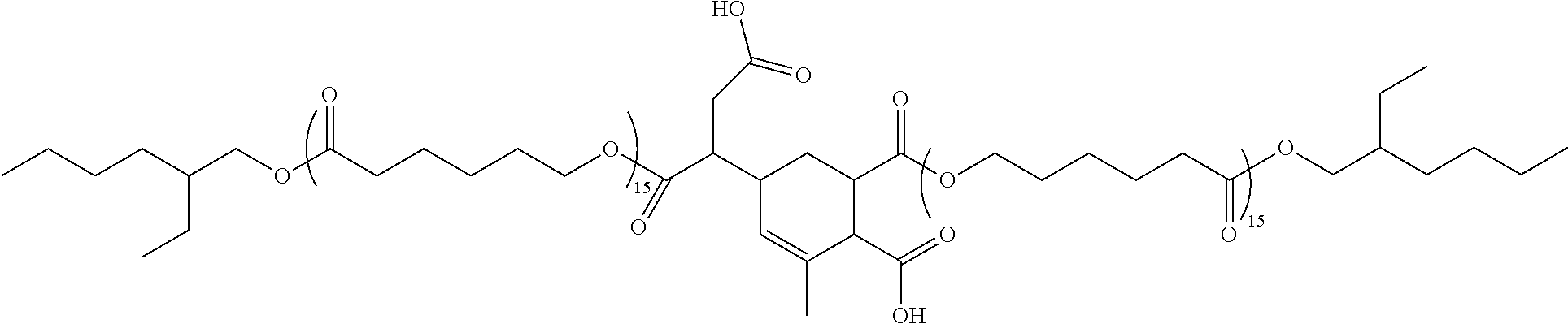
C00015
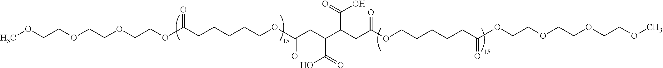
C00016
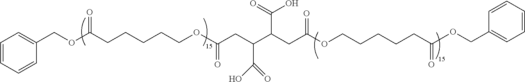
C00017
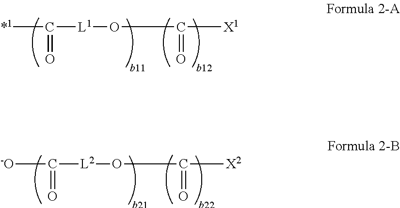
C00018
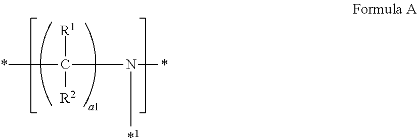
C00019
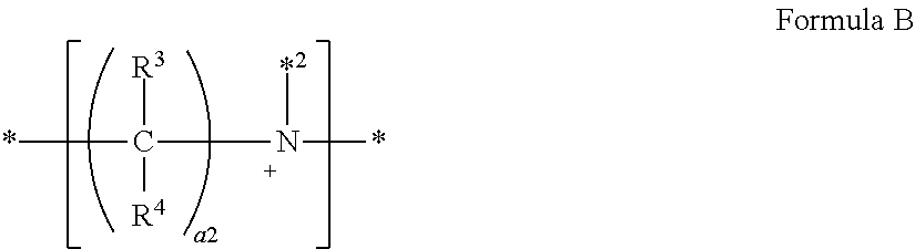
C00020

C00021
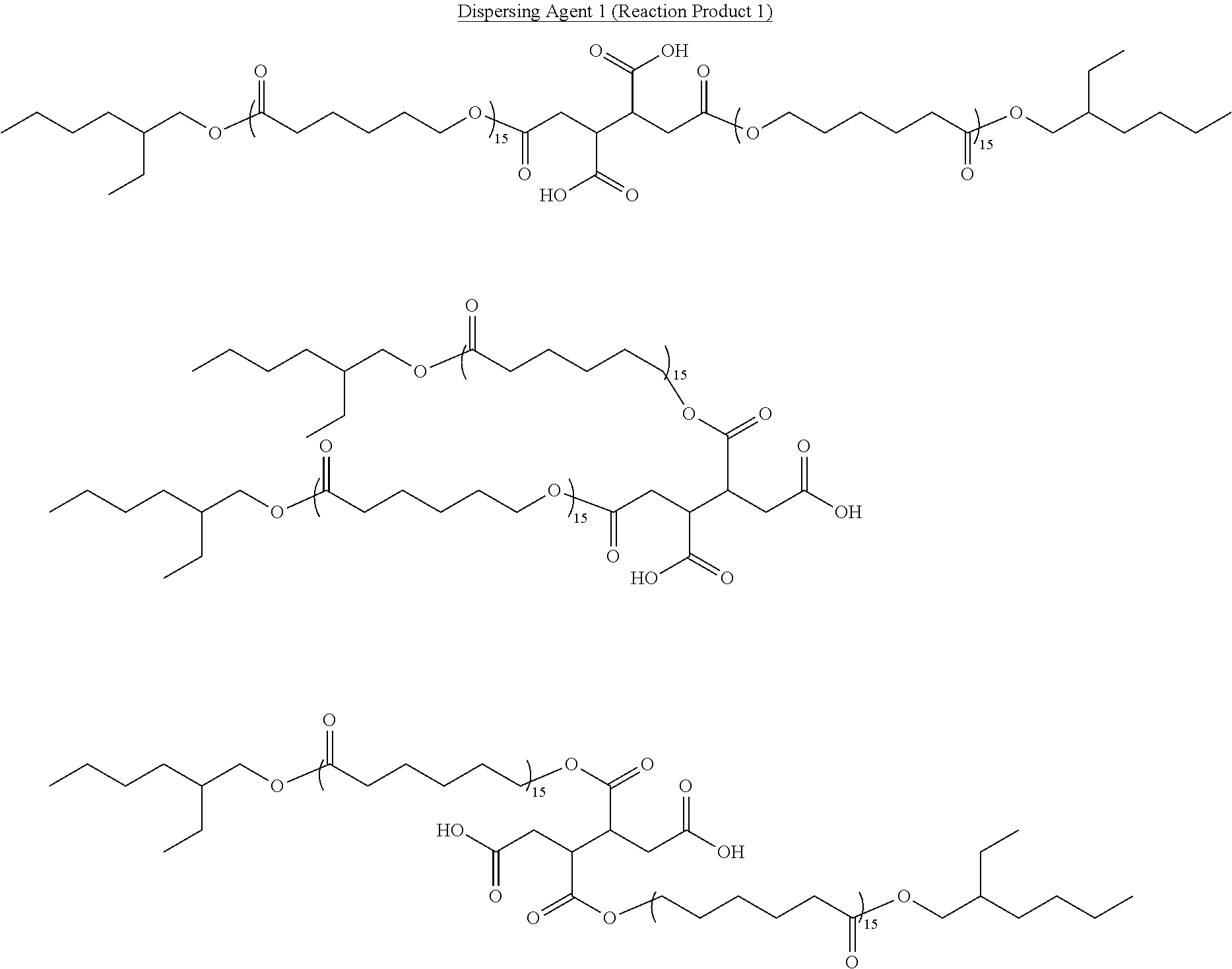
C00022
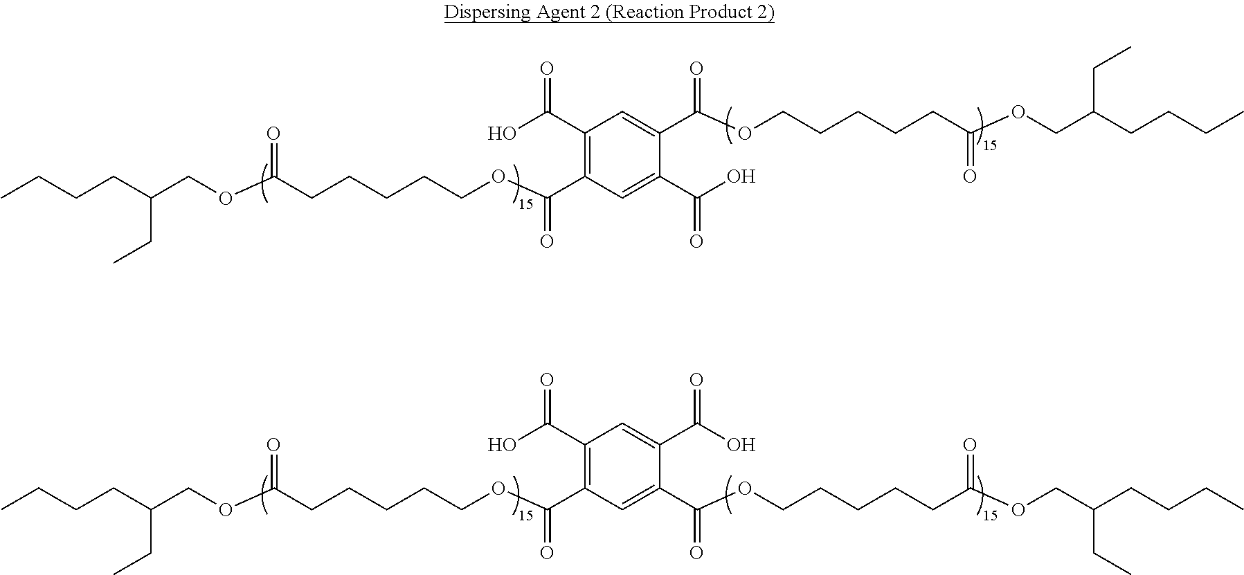
C00023

C00024
D00000
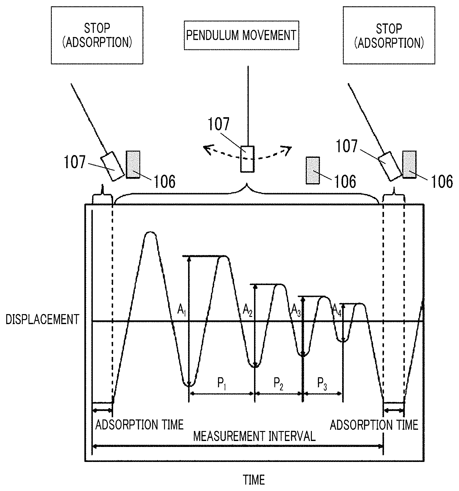
D00001
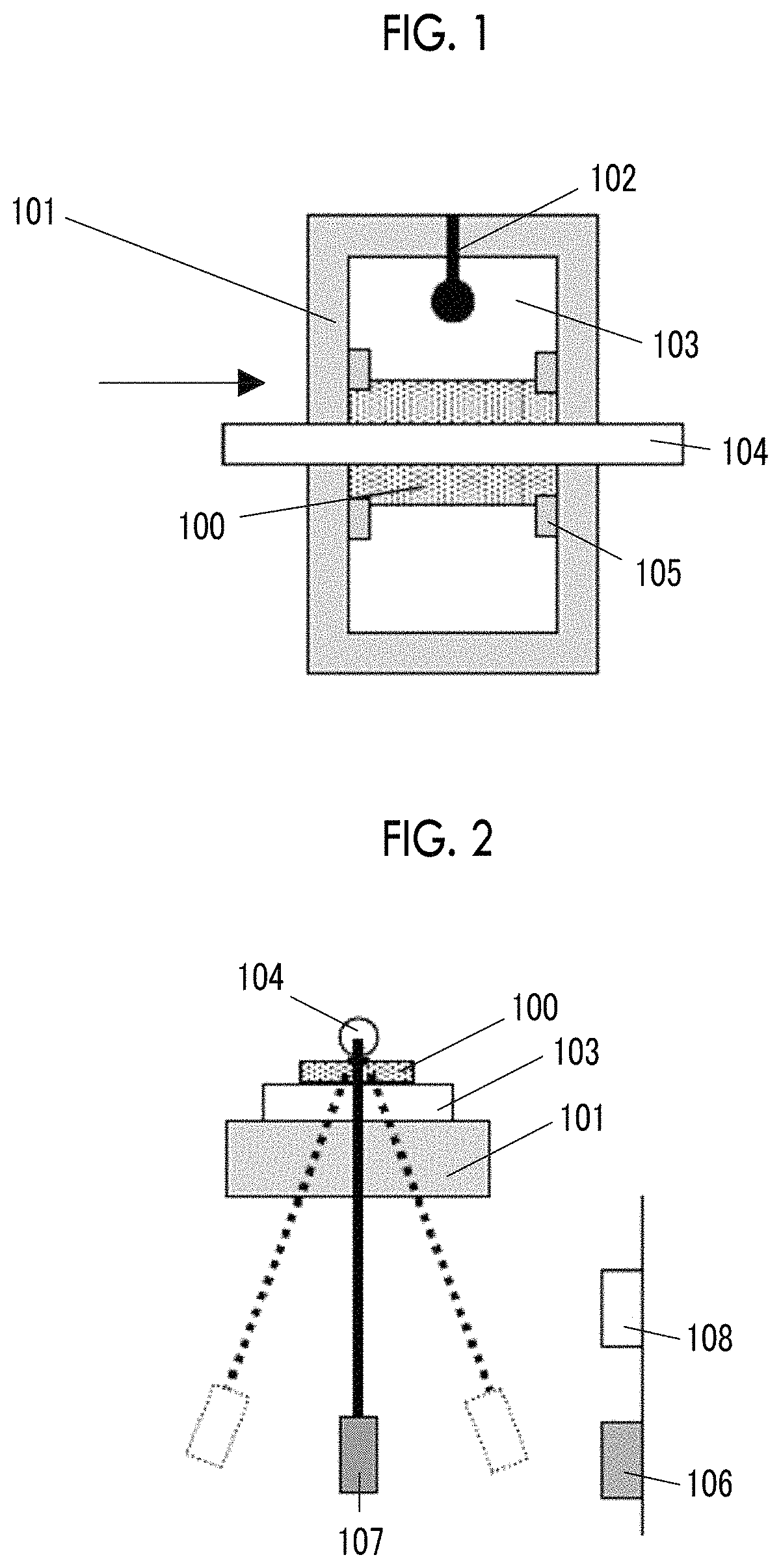
D00002
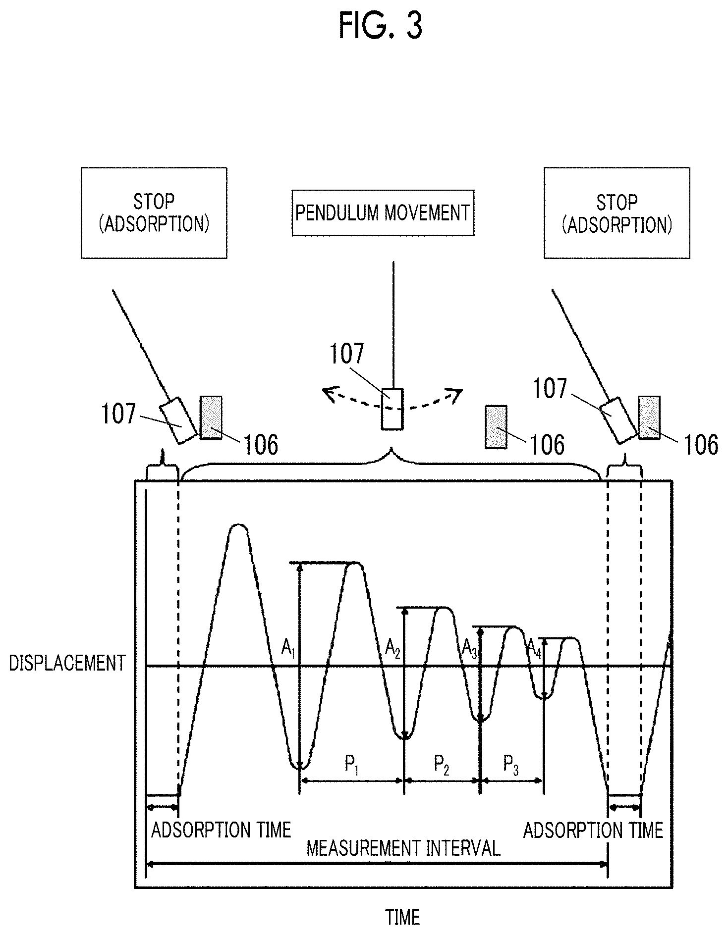
D00003
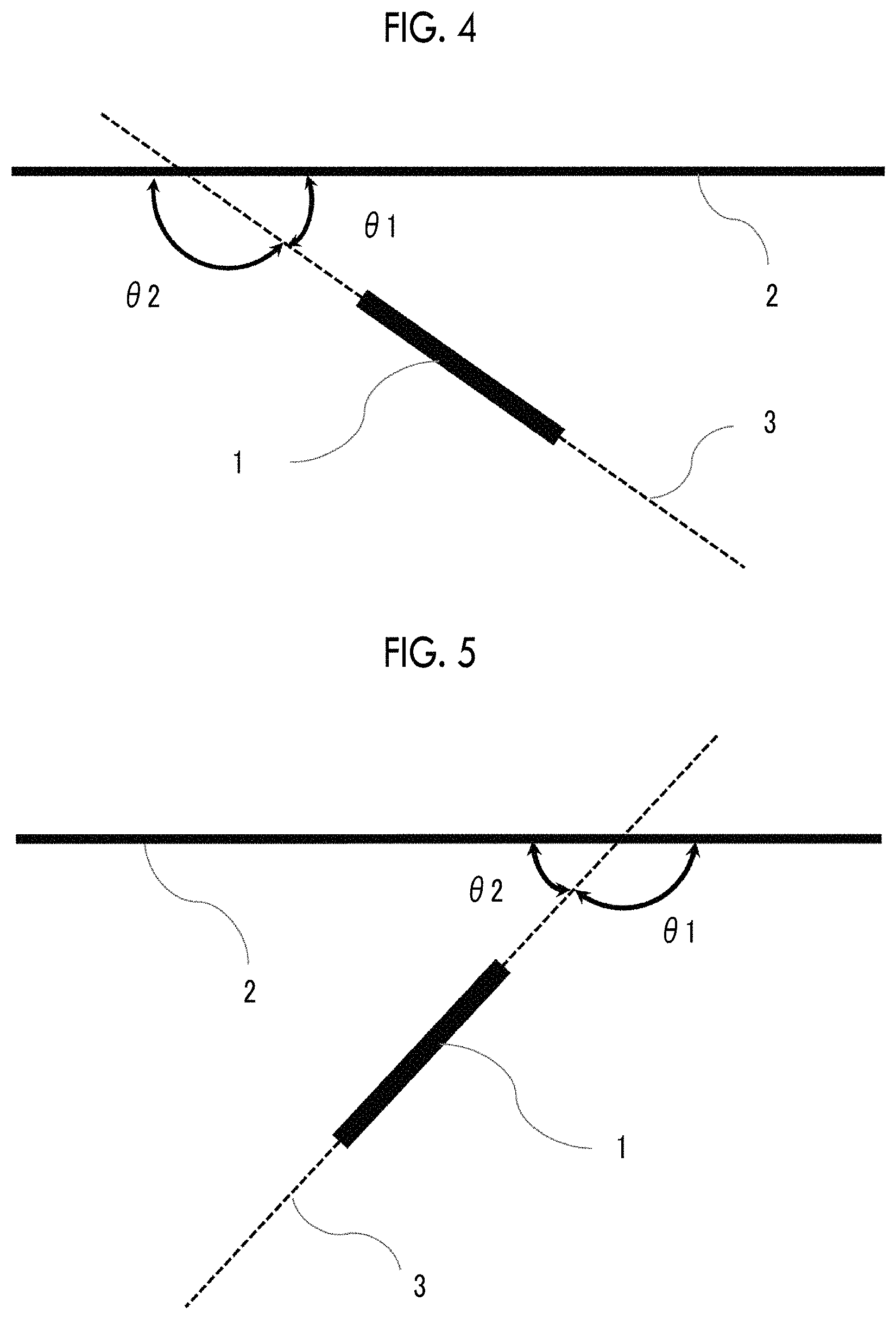
D00004
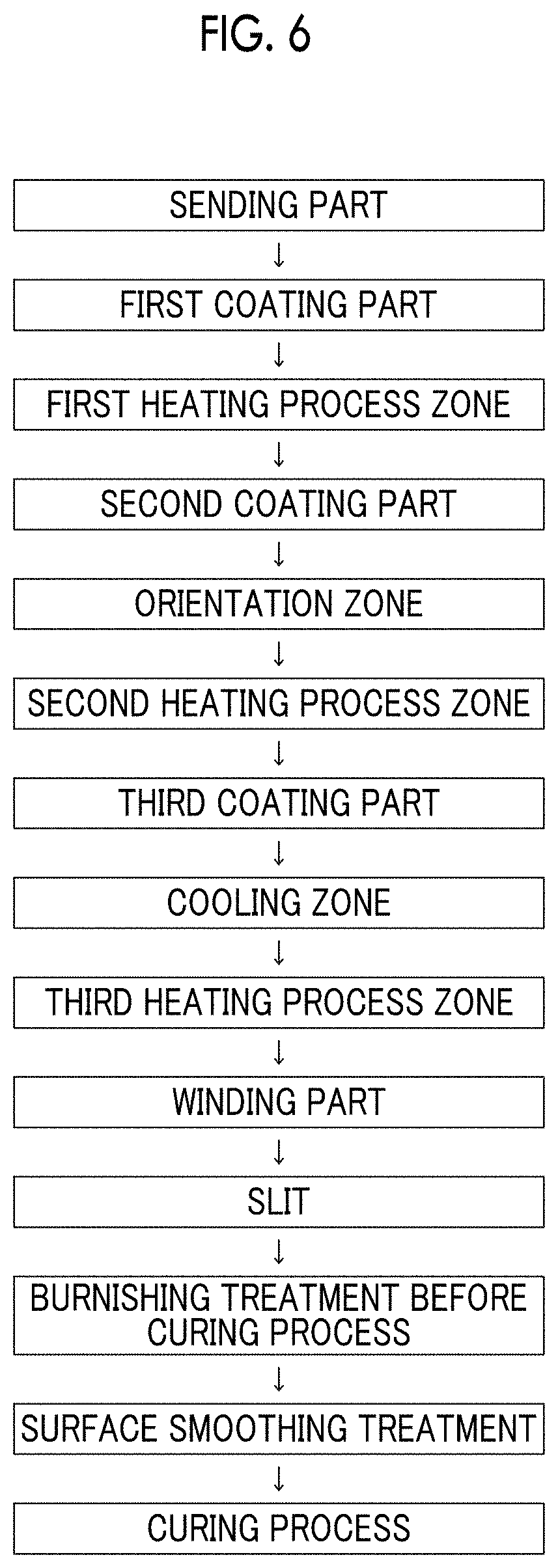
M00001

M00002

XML
uspto.report is an independent third-party trademark research tool that is not affiliated, endorsed, or sponsored by the United States Patent and Trademark Office (USPTO) or any other governmental organization. The information provided by uspto.report is based on publicly available data at the time of writing and is intended for informational purposes only.
While we strive to provide accurate and up-to-date information, we do not guarantee the accuracy, completeness, reliability, or suitability of the information displayed on this site. The use of this site is at your own risk. Any reliance you place on such information is therefore strictly at your own risk.
All official trademark data, including owner information, should be verified by visiting the official USPTO website at www.uspto.gov. This site is not intended to replace professional legal advice and should not be used as a substitute for consulting with a legal professional who is knowledgeable about trademark law.