Motor compressor unit with removable cartridge
Alban , et al. J
U.S. patent number 10,527,063 [Application Number 14/347,733] was granted by the patent office on 2020-01-07 for motor compressor unit with removable cartridge. This patent grant is currently assigned to Thermodyne SAS. The grantee listed for this patent is Thermodyn Sas. Invention is credited to Thomas Alban, Patrick Friez, Pierre Laboube.
| United States Patent | 10,527,063 |
| Alban , et al. | January 7, 2020 |
Motor compressor unit with removable cartridge
Abstract
A motor compressor unit including a common housing sealed with respect to a gas to be compressed, a motor mounted to the common housing, and a compressor mounted to the common housing. The motor is mounted in an inner casing fastened in the common housing by at least one removable fastening device such that the motor and the inner casing form a removable cartridge.
| Inventors: | Alban; Thomas (Le Creusot, FR), Laboube; Pierre (Le Creusot, FR), Friez; Patrick (Le Creusot, FR) | ||||||||||
|---|---|---|---|---|---|---|---|---|---|---|---|
| Applicant: |
|
||||||||||
| Assignee: | Thermodyne SAS (LeCreusot,
FR) |
||||||||||
| Family ID: | 46934574 | ||||||||||
| Appl. No.: | 14/347,733 | ||||||||||
| Filed: | September 25, 2012 | ||||||||||
| PCT Filed: | September 25, 2012 | ||||||||||
| PCT No.: | PCT/EP2012/068894 | ||||||||||
| 371(c)(1),(2),(4) Date: | March 27, 2014 | ||||||||||
| PCT Pub. No.: | WO2013/045459 | ||||||||||
| PCT Pub. Date: | April 04, 2013 |
Prior Publication Data
| Document Identifier | Publication Date | |
|---|---|---|
| US 20140234136 A1 | Aug 21, 2014 | |
Foreign Application Priority Data
| Sep 27, 2011 [FR] | 11 58638 | |||
| Current U.S. Class: | 1/1 |
| Current CPC Class: | F04D 25/0606 (20130101); F04D 17/122 (20130101); F04D 25/02 (20130101); F04D 29/624 (20130101); F04D 29/644 (20130101); F04D 29/4206 (20130101); F04D 29/601 (20130101) |
| Current International Class: | F04D 29/60 (20060101); F04D 29/62 (20060101); F04D 25/02 (20060101); F04D 29/64 (20060101); F04D 17/12 (20060101); F04D 25/06 (20060101); F04D 29/42 (20060101) |
| Field of Search: | ;417/360,423.12 ;384/493,557 |
References Cited [Referenced By]
U.S. Patent Documents
| 2291346 | July 1942 | Robinson |
| 3000543 | September 1961 | Paul |
| 3185099 | May 1965 | Spring |
| 3426690 | February 1969 | Cattabiani |
| 3604820 | September 1971 | Scheller |
| 3826597 | July 1974 | Schmitz |
| 4115038 | September 1978 | Litzenberg |
| 4184472 | January 1980 | Benedicto |
| 4648789 | March 1987 | Bowman |
| 4961260 | October 1990 | Ferri et al. |
| 5117138 | May 1992 | Trian |
| 5354182 | October 1994 | Niemiec |
| 5354187 | October 1994 | Holland |
| 5538406 | July 1996 | Siegal |
| 5618166 | April 1997 | Legett |
| 5627420 | May 1997 | Rinker et al. |
| 5971702 | October 1999 | Afton et al. |
| 6196809 | March 2001 | Takahashi |
| 6254360 | July 2001 | Sato |
| 6386845 | May 2002 | Bedard |
| 6474960 | November 2002 | Hansmann |
| 6860466 | March 2005 | Sakurai |
| 7458214 | December 2008 | Philippe |
| 2006/0123783 | June 2006 | Philippe |
| 2006/0157027 | July 2006 | Ichikawa |
| 2006/0181168 | August 2006 | Hargraves |
| 2006/0220473 | October 2006 | Ueda |
| 2006/0228238 | October 2006 | Andrews |
| 2007/0084439 | April 2007 | Isogai |
| 2007/0086903 | April 2007 | Schopperle |
| 2007/0257569 | November 2007 | Heyder |
| 2008/0087018 | April 2008 | Woollenweber |
| 2009/0162226 | June 2009 | Campbell |
| 2009/0196764 | August 2009 | Fogarty et al. |
| 2011/0002799 | January 2011 | McVicker |
| 1473462 | Nov 2004 | EP | |||
| 1826887 | Aug 2007 | EP | |||
| 1830070 | Sep 2007 | EP | |||
Other References
|
International Search Report and Written Opinion dated Jan. 31, 2013 which was issued in connection with PCT Application No. PCT/EP12/068894 which was filed on Sep. 25, 2012. cited by applicant. |
Primary Examiner: Freay; Charles G
Attorney, Agent or Firm: Baker Hughes Patent Organization
Claims
What is claimed is:
1. A motor compressor unit comprising: a common housing sealed with respect to a gas to be compressed; a motor mounted to the common housing; a compressor mounted to the common housing; and a first bearing mounted on a first bearing support, the first bearing support mounted to a first end of an inner casing facing the compressor; a second bearing mounted on a second bearing support, the second bearing support mounted to a second end of the inner casing, the second end of the inner casing located opposite the first end of the inner casing; wherein the motor is mounted in the inner casing, wherein the inner casing, in entirety, is removably mounted in the common housing, and wherein the inner casing is held in position in the common housing by at least one removable fastening device configured to apply an axial force to seal the common housing.
2. The motor compressor unit according to claim 1, wherein the motor comprises a stator fixed to the inner casing.
3. The motor compressor unit according to claim 1, wherein the at least one removable fastening device comprises a key member located between the inner casing and the common housing.
4. The motor compressor unit according to claim 1, wherein the common housing comprises a shoulder on which the first end of the inner casing facing the compressor bears.
5. The motor compressor unit according to claim 1, further comprising a cover configured to seal the common housing at an end of the common housing through which the inner casing is inserted into the common housing, the cover being attached, by screwing, to the second bearing support.
6. The motor compressor unit according to claim 1, wherein the second bearing support is fastened to the common housing at an end of the common housing through which the inner casing is inserted into the common housing.
7. The motor compressor unit according to claim 1, wherein the inner casing is kept in position axially by keying, using a key member as the at least one removable fastening device, to the common housing at an end of the common housing through which the inner casing is inserted into the common housing.
8. The motor compressor unit according to claim 1, wherein a cover, configured to seal the common housing at an end of the common housing through which the inner casing is inserted into the common housing comprises a sealed axial wiring outlet.
9. The motor compressor unit according to claim 1, wherein a cover, configured to seal the common housing at an end of the common housing through which the inner casing is inserted into the common housing, comprises an axial gas supply inlet.
10. The motor compressor unit according to claim 1, further comprising a cover configured to seal the common housing at an end of the common housing through which the inner casing is inserted into the common housing, the cover being attached, by screwing, to the common housing.
11. The motor compressor unit according to claim 1, wherein the common housing comprises a sealed radial wiring outlet passing through the common housing.
12. The motor compressor unit according to claim 10, wherein the common housing comprises a sealed radial gas supply inlet passing through the common housing.
13. The motor compressor unit according to claim 1, wherein the compressor comprises a plurality of compression stages.
14. A motor compressor unit comprising: a common housing sealed with respect to a gas to be compressed; a motor mounted to the common housing; a compressor mounted to the common housing; and at least one bearing support for the motor, the at least one bearing support fastened to an end of an inner casing opposite an end of the inner casing facing the compressor and in a manner that allows for axial expansion, wherein the motor is mounted in the inner casing, wherein the inner casing, in entirety, is removably mounted in the common housing, and wherein the inner casing is held in position in the common housing by at least one removable fastening device such that the motor and the inner casing form a removable cartridge.
Description
BACKGROUND OF THE INVENTION
Embodiments of the present invention relate to a high-speed electric motor of the integrated type, and more specifically to a high-speed motor compressor or turbo-compressor unit of the integrated type with a removable cartridge.
A high-speed motor is a motor whose rotation frequency is greater than the frequency of the electrical power network. A high-speed motor typically has a rotation speed of more than 3600 r.p.m.
A conventional integrated motor compressor unit is shown in part in FIG. 1. It comprises a sealed housing C in which are mounted an electric motor M and a compressor unit which is not shown, for example a multiple stage unit, which includes a plurality of compression impellers carried on an output shaft coupled to a rotor driven by the motor M.
The housing C, sealed by a cover T, has a first casing E.sub.C for containing the compressor, assembled together with a second casing E.sub.V in which the electric motor M is mounted. The electric motor M has a rotor R, a stator S, and first and second bearings P.sub.1 and P.sub.2 supporting the motor shaft, which are mounted, respectively, on a first and a second bearing support SP.sub.1 and SP.sub.2 positioned at either end of the rotor R.
The bearing supports SP.sub.1 and SP.sub.2 are mounted directly on the second casing E.sub.V. In this arrangement, the second support SP.sub.2 impedes access to the rotor R, and the first support SP.sub.1 can only be accessed by removing the first casing E.sub.C from the second casing E.sub.V.
The stator S of the motor M is shrink-fitted directly on to the motor casing E.sub.V, and therefore cannot be removed. The motor casing E.sub.V comprises a high-voltage wiring outlet O formed in a sealed way on a radial part of the housing C. This high-voltage outlet O is usually non-removable.
Removable cartridge systems are generally used by manufacturers of compressors and pumps. For example, in a compressor with a removable cartridge, the aerodynamic stator parts and the rotor are combined in a cartridge having a cylindrical outer shape which can be fitted into the main housing enabling the pressure to be adjusted. The bearings may be external to this cartridge or may be attached to the ends of the cartridge.
Various prior art documents relate to such arrangements.
U.S. Pat. No. 3,826,597 describes the use of a concept of this type in specific rotating machine applications such as vane-type compressors.
U.S. Pat. Nos. 5,971,702 and 4,961,260 describe principles of cartridge centring and insertion for centrifugal compressor applications.
With regard to the application of this concept to electrical machines, the U.S. Pat. Nos. 5,117,138 and 5,627,420 describe a removable electric motor stator. However, this patent is concerned with submersible pump applications. Furthermore, the removable stator is encapsulated in order to isolate it from the process gas, and the bearings are completely separated from this stator.
Finally, the U.S. Pat. No. 7,458,214 relates to a turbocharger application composed of a turbine wheel and a compressor wheel mounted in a projecting manner, and equipped with an auxiliary electric motor with a removable stator.
In the last three documents, the stator is not encapsulated, and in U.S. Pat. No. 7,458,214 the bearings are always separated from the stator.
BRIEF DESCRIPTION OF THE INVENTION
In view of the above considerations, it is proposed that the drawbacks of prior art integrated motor compressor units be overcome by proposing a motor compressor unit comprising a cartridge which includes the whole of the stator, the bearings and the rotor, and which can easily be removed from the housing to facilitate the maintenance thereof.
According to one aspect, a motor compressor unit is proposed, comprising a motor, a compressor and a common housing sealed with respect to the gas to be compressed, in which the motor and compressor are mounted.
The motor is mounted in an inner casing fastened in the housing by removable fastening means such that the motor and inner casing form a removable cartridge.
The combination of the motor and inner casing into a removable cartridge facilitates the removal of the whole motor without the need to remove other elements of the motor compressor such as, notably, the coupling between the outer casing of the motor and the casing of the compressor, in cases where the housing is composed of a compressor casing and an outer motor casing.
Furthermore, since the motor is entirely assembled into a removable cartridge, it is possible to propose the use of a housing comprising a compressor casing and an outer motor casing. It is possible for the housing to be composed of a single casing into which the inner casing containing the motor is inserted. In this case, the elimination of a vertical coupling plane between the compressor casing and the outer motor casing reduces the risk of leakage due to the ageing of the joints at this coupling, and reduces the production cost because of the elimination of the joints and the associated grooves.
Furthermore, since all the elements of the motor are contained in the inner casing, access to all the motor components is facilitated.
The stator of the motor may be integral with the inner casing of the motor. Shrink-fitting the stator on to the inner casing, and more particularly on to the inner surface of the inner casing, causes the stator to be immobilized with respect to the inner casing on the one hand, and with respect to the housing on the other hand, once the inner casing has been fastened to the housing.
The motor compressor unit may comprise a key member between the inner casing and the housing, by means of which the inner casing is fixed to the housing, the motor torque is recovered and any rotation of the inner casing inside the housing is prevented.
The housing may comprise a shoulder on which one end of the inner casing, facing the compressor, bears.
The housing may comprise a first bearing support for the motor, said first support being fastened to one end of the inner casing facing the compressor. The first bearing support can be fixed by screwing on to the inner casing without any play, in such a way that the removable cartridge comprises the first bearing support, which can thus be withdrawn together with the removable cartridge.
The housing can comprise a second bearing support for the motor, said second support being fastened to one end of the inner casing opposite the end facing the compressor, by means of a semi-rigid link which can compensate for the relative expansion between the inner casing and the second bearing support.
In a first and a second embodiment, the motor compressor unit comprises a cover which can seal the housing at an end through which the inner casing is inserted into the housing, the cover being fastened to the second bearing support by screwing.
In the first embodiment, the inner casing is held in position axially by keying to the housing at one end through which the inner casing is inserted into the housing. The second bearing support and the cover are axially retained by means of a ring (Circlip.RTM.) inserted into a groove formed in the housing. The removable cartridge can be extracted from the housing by simply withdrawing the key member, and in this case the removable cartridge comprises the inner casing and its contents, the second bearing support, and the cover.
In the second embodiment, the second support is fastened to said housing at the end through which the inner casing is inserted into the housing. In this second embodiment, the removable cartridge can be extracted from the housing by simply detaching the second bearing support from the housing, without detaching the second bearing support, to which the cover is fastened, from the inner casing.
In the first and second embodiments, the cover can comprise a sealed axial high-voltage wiring outlet.
Additionally, in the first and second embodiments, the cover can comprise an axial gas supply inlet.
In a third embodiment, the motor compressor unit can comprise a cover which can seal the housing at an end through which the inner casing is inserted into the housing, the cover being fastened to the housing by screwing. In this embodiment, the removable cartridge can be extracted from the housing by simply detaching the cover from the housing.
In this third embodiment, the housing can comprise a sealed radial high-voltage wiring outlet passing through the inner motor casing and the housing.
In this third embodiment, the housing can also comprise a radial gas supply inlet passing through the outer motor casing and the housing.
In various embodiments, the compressor can comprise a plurality of compression stages.
BRIEF DESCRIPTION OF THE DRAWINGS
Other advantages and features of the invention will be made clear by the detailed description of embodiments which are not in any way limiting, and the attached drawings, in which:
FIG. 1 shows part of an integrated motor compressor unit including the motor according to the prior art;
FIG. 2 shows a motor compressor unit with a removable cartridge according to one embodiment of the present invention;
FIG. 3 shows part of a motor compressor unit with a removable cartridge according to one embodiment of the present invention;
FIG. 4 shows part of a motor compressor unit with a removable cartridge according to one embodiment of the present invention;
DETAILED DESCRIPTION OF THE EXEMPLARY EMBODIMENTS OF THE INVENTION
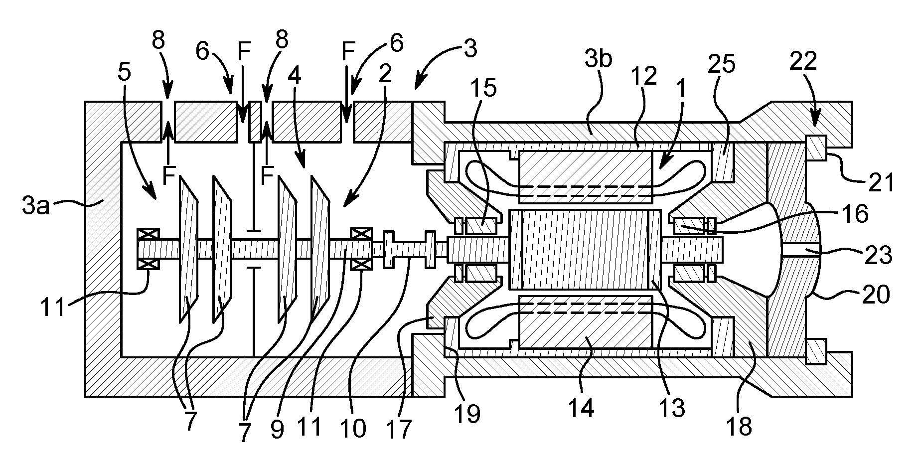
FIG. 2 shows a motor compressor unit with a removable cartridge according to a first embodiment.
The whole of the motor compressor unit, and in particular, the motor 1 and the compressor unit 2, is mounted in a common housing 3 which is sealed with respect to the internal gas handled by the compressor. In the illustrated example, the common housing 3 comprises an assembly of housings 3a and 3b which are fixed together and which support and protect the compressor 2 and the motor 1, respectively. The housings 3a and 3b are fixed together by appropriate fastening means (not shown) enabling the housings to be fastened to each other in a rigid and sealed way. The common housing 3 may also be made in one piece.
In this case, the compressor unit 2 comprises a first compression stage 4 and a second stage 5. Each of the compression stages 4 and 5 comprises impellers 7 which compress the incoming gas delivered at the inlet by a gas inlet opening 6 formed in the housing 3a, while an outlet opening 8 collects the processed gas. An arrow F indicates the direction of the flow of the gas. The impellers 7 are mounted on an output shaft 9 coupled to the motor 1 via a coupling piece 10. The output shaft 9 is kept in position with the aid of two radial bearings 11 mounted, one on each end of the output shaft 9.
The motor 1 includes a rotor 13, a stator 14 and two bearings 15 and 16, mounted, respectively, on a first support 17 and a second support 18 at either end of the rotor 13. The assembly is mounted in a cylindrical inner casing 12 mounted removably with respect to the housing 3b.
The stator 14 is shrink-fitted on to the inner surface of the inner casing 12 in such a way that it is integral with the inner casing 12. A key member between the inner casing 12 and the housing 3b is used to recover the motor torque and prevent any rotation of the stator 14.
The bearings 15 and 16 provide radial support for the rotor 13. In this first exemplary embodiment, the first bearing 15 is mounted on the first support 17, which is itself fastened to one end of the inner casing 12 facing the compressor 2. The second bearing 16 is mounted on the second support 18, which is fastened to one end of the inner casing 12 opposite the end facing the compressor 2 by means of a semi-rigid link 25 enabling the axial expansion of the inner casing 12 to be compensated. The first support 17 and the second support 18 are thus fastened, respectively, to each of the ends of the inner casing 12.
The casing 3b comprises a shoulder 19, on which the end of the inner casing 12 facing the compressor 2, in other words the end at which the motor 1 is coupled to the compressor 2, bears.
The housing 3b also comprises a cover 20 enabling the housing 3b to be sealed at an end through which the inner casing 12 is inserted into the housing 3b. The cover 20 is screwed into the bearing support 18. When the removable cartridge, comprising the inner casing 12 and the motor 1, has been coupled to the cover 20, it is inserted into the housing 3b. The cover 20 and the bearing support 18 are then held in position with the aid of a key member, for example a Circlip.RTM. 21 inserted into a groove 22 provided for this purpose in the housing 3b.
Thus, the arrangement shown in this first example makes it possible to provide a removable cartridge comprising the inner casing 12, the rotor 13, the stator 14, the cover 20, and the bearings 15 and 16 which are mounted, respectively, on the first support 17 and the second support 18, which are fixed to the inner casing 12. When the key member 21 and then the cover 20 have been withdrawn, the removable cartridge can thus be withdrawn for any necessary maintenance operation and can then be re-inserted into the housing without the need to remove other elements of the motor compressor unit.
The cover 20 also comprises an axial high-voltage wiring outlet 23. This axial outlet 23 is sealed in such a way that the interior of the housing 3 is kept pressurized during operation. The axial outlet 23, thus, allows the removable cartridge to be withdrawn without preliminary disconnection of wiring. In fact, once the Circlip.RTM. has been withdrawn, the cartridge can be extracted from the housing 3b without any need to remove the high-voltage wiring between the motor and the cover 20.
Additionally, the motor compressor unit also comprises an inlet for the supply of cooling gas. This gas supply, which is not shown, can be provided either radially through the housing 3b and the inner casing 12, or axially, in which case the cover 20 comprises an axial gas supply inlet.
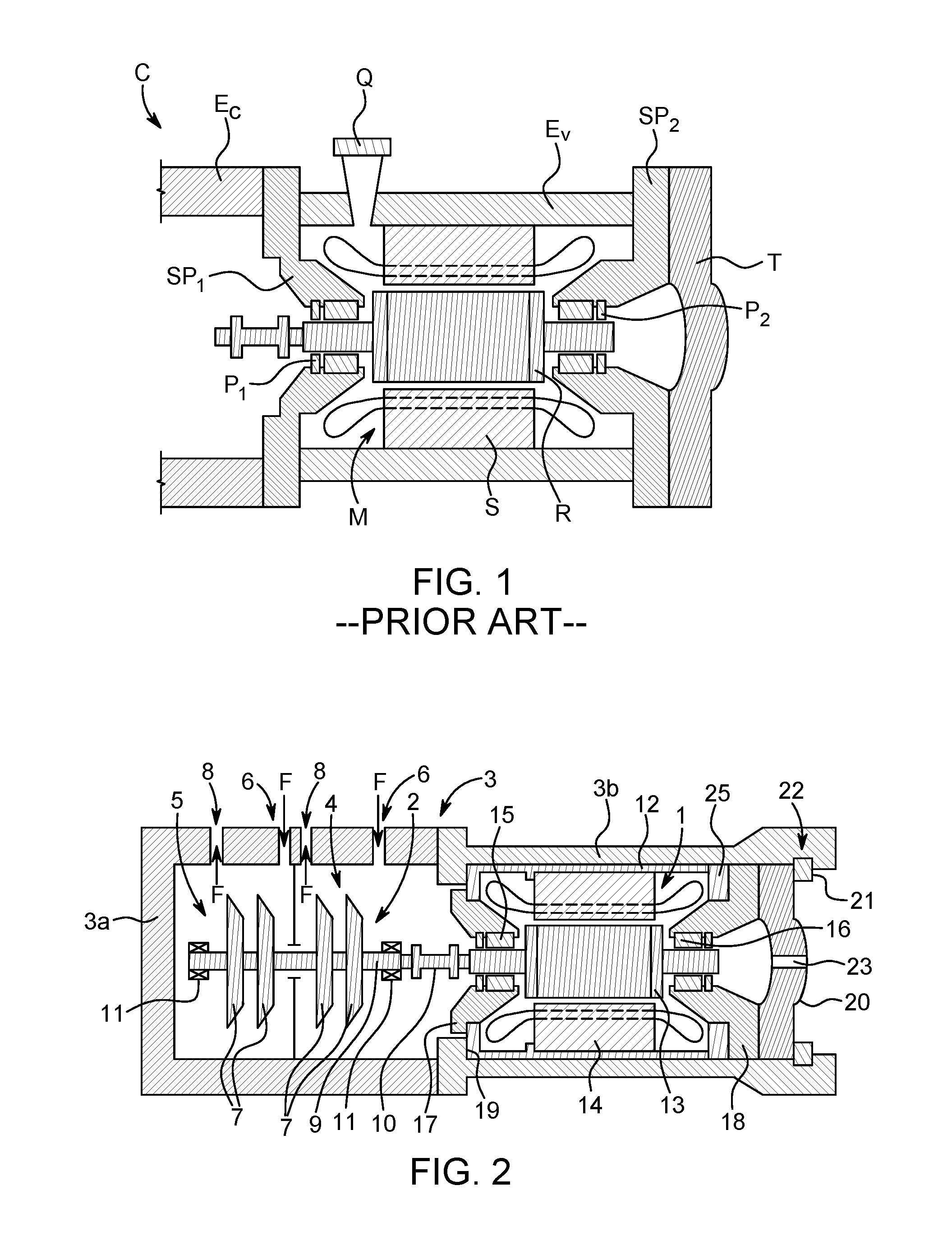
FIG. 3 shows part of a motor compressor unit with a removable cartridge according to a second embodiment. Only the part of the housing 3 containing the motor 1, in this case the housing 3b, is shown in FIG. 3, the part of the motor compressor unit containing the compressor 2 being similar to that shown in FIG. 2.
Elements identical to the elements of the first embodiment shown in FIG. 2 have the same references.
In this example, the housing 3 comprises a second support 180 fastened to the housing 3b at an end through which the inner casing 12 is inserted, and the cover 190 is fastened by screwing to this second support 180. This attached support 180 is generally annular in shape and has an essentially central extension supporting a bearing 16 for the motor shaft. This second support 180 is also connected to the inner casing 12 by means of a semi-rigid fastening enabling the axial expansion of said inner casing to be compensated.
When the support 180 is detached from the housing 3d, the removable cartridge, comprising the inner casing 12, the rotor 13, the stator 14, the cover 20, and the bearings 15 and 16 which are mounted, respectively, on the first support 17 and the second support 180, can be withdrawn.
In this example, the cover 200 comprises an axial high-voltage wiring outlet 230. This axial outlet 230 is sealed in such a way that the interior of the housing 3 is kept pressurized during operation. The axial outlet 230, thus, allows the removable cartridge to be withdrawn without preliminary disconnection of wiring. In fact, the cartridge can be extracted from the housing 3b at the same time as the cover 200 without any need to remove the high-voltage wiring between the motor and the cover 200.
Additionally, the motor compressor unit also comprises an inlet for the supply of gas. This gas supply, which is not shown, can be provided either radially through the housing 3b and the inner casing 12, or axially, in which case the cover 200 comprises an axial gas supply inlet.
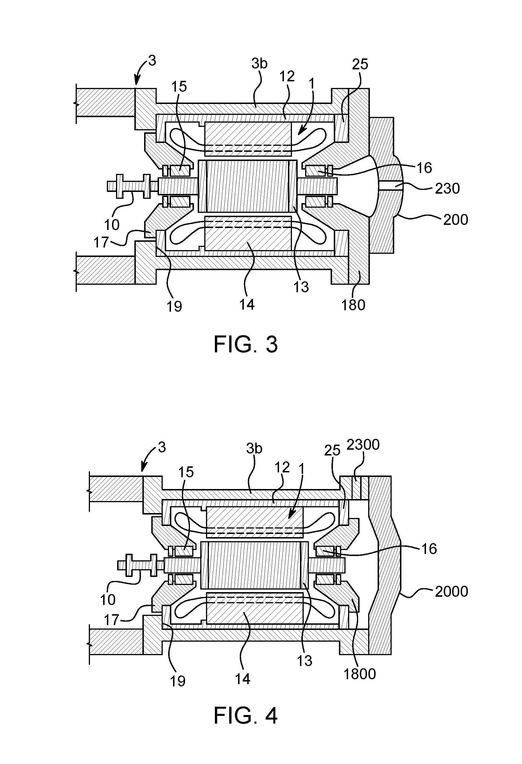
FIG. 4 shows part of a motor compressor unit with a removable cartridge according to a third embodiment. Only the part of the housing 3 containing the motor 1, namely the housing 3b, is shown in FIG. 4. The part of the motor compressor unit containing the compressor 2 being similar to that shown in FIG. 2.
Elements identical to the elements of the first embodiment shown in FIG. 2 have the same references.
In this example, the housing 3b comprises a second support 1800 carrying the bearing 16 and fastened to an end of the inner casing 12 opposite to the end facing the compressor 2, and a cover 2000 fastened by screwing to an end of the housing 3 through which the inner casing 12 is inserted into the housing 3b.
In this example, the removable cartridge does not comprise the cover 2000, as the latter is in contact with the housing 3 only. Instead of being screwed on to the housing 3, the cover 2000 can be retained axially with respect to the housing 3 with the aid of a Circlip.RTM. inserted into a groove provided for this purpose in the motor casing 3b, on the same principle as that illustrated in FIG. 2.
In this example, the high-voltage wiring outlet is formed radially. For this purpose, the housing 3 comprises a sealed radial high-voltage wiring outlet passing through the housing 3. This radial outlet 2300 is sealed in such a way that the interior of the housing 3 is kept pressurized during operation. The internal connections are formed in such a way that the wiring can be cut between the sealed radial outlet 2300 and the removable cartridge when the removable cartridge is withdrawn.
Thus, during disassembly, the cover 2000 is first withdrawn, after which the wiring between the removable cartridge and the sealed radial outlet 2300 are disconnected at the internal connections provided for this purpose, and the removable cartridge is then extracted from the housing 3.
The motor compressor unit also comprises an inlet for the supply of gas. This gas supply, which is not shown, can be provided either radially through the housing 3b and the inner casing 12, or axially, in which case the cover 2000 comprises an axial gas supply inlet.
Although the present invention has been described with reference to particular embodiments, this description generally aims to set forth the inventive ideas and should not be taken to limit the scope of the present invention, and the scope of the present invention will be defined by the appended claims. Of course, those skilled in the art will also be appreciated that the present invention may be performed in other ways than those specifically described herein, without departing from the basic characteristics of the present invention. The present embodiments are thus to be considered in all respects as illustrative and not restrictive, and all changes which come within the meaning and range of equivalency of the appended claims are intended to included therein.
* * * * *
D00000
D00001
D00002
XML
uspto.report is an independent third-party trademark research tool that is not affiliated, endorsed, or sponsored by the United States Patent and Trademark Office (USPTO) or any other governmental organization. The information provided by uspto.report is based on publicly available data at the time of writing and is intended for informational purposes only.
While we strive to provide accurate and up-to-date information, we do not guarantee the accuracy, completeness, reliability, or suitability of the information displayed on this site. The use of this site is at your own risk. Any reliance you place on such information is therefore strictly at your own risk.
All official trademark data, including owner information, should be verified by visiting the official USPTO website at www.uspto.gov. This site is not intended to replace professional legal advice and should not be used as a substitute for consulting with a legal professional who is knowledgeable about trademark law.