Device for assisting or automatic guiding of a motor vehicle
Witte J
U.S. patent number 10,526,004 [Application Number 14/439,519] was granted by the patent office on 2020-01-07 for device for assisting or automatic guiding of a motor vehicle. This patent grant is currently assigned to Volkswagen AG. The grantee listed for this patent is VOLKSWAGEN AG. Invention is credited to Bastian Witte.


View All Diagrams
| United States Patent | 10,526,004 |
| Witte | January 7, 2020 |
Device for assisting or automatic guiding of a motor vehicle
Abstract
A device for assisting or automatic guiding of a motor vehicle, having a first steering actuator with an allocated steering control unit, a gear rack, a steering column and a steering handle, wherein the steering column and the steering actuator have effect on the common gear rack, wherein there is at least one second steering actuator having an additional allocated steering control unit, wherein the second steering actuator has effect on the common gear rack.
| Inventors: | Witte; Bastian (Gross Schwulper, DE) | ||||||||||
|---|---|---|---|---|---|---|---|---|---|---|---|
| Applicant: |
|
||||||||||
| Assignee: | Volkswagen AG
(DE) |
||||||||||
| Family ID: | 49448127 | ||||||||||
| Appl. No.: | 14/439,519 | ||||||||||
| Filed: | October 15, 2013 | ||||||||||
| PCT Filed: | October 15, 2013 | ||||||||||
| PCT No.: | PCT/EP2013/071513 | ||||||||||
| 371(c)(1),(2),(4) Date: | April 29, 2015 | ||||||||||
| PCT Pub. No.: | WO2014/067773 | ||||||||||
| PCT Pub. Date: | May 08, 2014 |
Prior Publication Data
| Document Identifier | Publication Date | |
|---|---|---|
| US 20150298722 A1 | Oct 22, 2015 | |
Foreign Application Priority Data
| Oct 30, 2012 [DE] | 10 2012 021 436 | |||
| Current U.S. Class: | 1/1 |
| Current CPC Class: | B62D 5/04 (20130101); B62D 5/0421 (20130101); B62D 5/003 (20130101) |
| Current International Class: | B62D 5/00 (20060101); B62D 5/04 (20060101) |
| Field of Search: | ;180/407 |
References Cited [Referenced By]
U.S. Patent Documents
| 4577738 | March 1986 | Yater |
| 4681183 | July 1987 | Oshita |
| 5327986 | July 1994 | Saita |
| 6394218 | May 2002 | Heitzer |
| 6543569 | April 2003 | Shimizu |
| 7222008 | May 2007 | Takahashi |
| 7686125 | March 2010 | Andersson |
| 7789784 | September 2010 | Hayashi |
| 9079604 | July 2015 | Di Giusto |
| 9272727 | March 2016 | Kometani |
| 2002/0063012 | May 2002 | Katou |
| 2003/0051938 | March 2003 | Menjak |
| 2003/0221895 | December 2003 | Palakodati |
| 2004/0007416 | January 2004 | Furumi |
| 2004/0026158 | February 2004 | Rieth et al. |
| 2005/0072621 | April 2005 | Hara |
| 2005/0234614 | October 2005 | Sakurai |
| 2005/0257992 | November 2005 | Shiino et al. |
| 2006/0054378 | March 2006 | Tanaka |
| 2006/0055139 | March 2006 | Furumi |
| 2006/0144636 | July 2006 | Beutler |
| 2007/0198152 | August 2007 | Endo |
| 2008/0011537 | January 2008 | Ozsoylu |
| 2008/0035411 | February 2008 | Yamashita |
| 2008/0059034 | March 2008 | Lu |
| 2008/0091320 | April 2008 | Sakai |
| 2008/0208366 | August 2008 | Dalby |
| 2008/0244029 | October 2008 | Soga |
| 2009/0242219 | October 2009 | Dunn |
| 2009/0260468 | October 2009 | Tachikake |
| 2010/0030426 | February 2010 | Okita |
| 2010/0235053 | September 2010 | Iwakiri |
| 2010/0286872 | November 2010 | Endo |
| 2011/0127742 | June 2011 | Bae |
| 2012/0046832 | February 2012 | Kariatsumari |
| 2012/0181102 | July 2012 | Bando |
| 2012/0239252 | September 2012 | Sawada |
| 2012/0241244 | September 2012 | Escobedo |
| 2012/0265405 | October 2012 | Matsumura |
| 2012/0298439 | November 2012 | Ji |
| 2013/0173832 | July 2013 | Calvin |
| 2013/0297150 | November 2013 | Kim |
| 2014/0214277 | July 2014 | Brenner |
| 2017/0373821 | December 2017 | Arakawa |
| 69213363 | Jan 1997 | DE | |||
| 19902556 | Jul 2000 | DE | |||
| 19947265 | Jul 2000 | DE | |||
| 10039170 | Jun 2001 | DE | |||
| 10160716 | Jun 2003 | DE | |||
| 202004003949 | Jun 2004 | DE | |||
| 102004033686 | Feb 2006 | DE | |||
| 60312350 | Jul 2007 | DE | |||
| 102008008182 | Oct 2009 | DE | |||
| 102011055820 | Jun 2012 | DE | |||
| 1375300 | Jan 2004 | EP | |||
Other References
|
Search Report for German Patent Application No. 10 2012 021 436.7; dated Jun. 7, 2013. cited by applicant . Search Report for International Patent Application No. PCT/EP2013/071513; dated May 8, 2014. cited by applicant. |
Primary Examiner: Rocca; Joseph M
Assistant Examiner: Duda; Conan D
Attorney, Agent or Firm: Barnes & Thornburg LLP
Claims
The invention claimed is:
1. A device for automated guiding of a transportation vehicle, the device comprising: a first steering actuator with an assigned steering control unit to provide automated guiding of the transportation vehicle; a gear rack; a steering column; a steering handle, the steering column and the first steering actuator having an effect on the gear rack; a second steering actuator with a further assigned steering control unit to provide automated guiding of the transportation vehicle, the second steering actuator having an effect on the gear rack, and a higher-level control unit arranged in communication with each of the assigned steering control unit of the first steering actuator and the further assigned steering control unit of the second steering actuator to communicate setpoint values, wherein the assigned steering control unit and the further assigned steering control unit are arranged in communication with each other to provide setpoint values from at least one of the assigned steering control units to the other under fault conditions.
2. The device of claim 1, wherein the fault conditions include fault of a bus system providing communication between the higher-level control unit and the one of the assigned steering control units.
3. The device of claim 1, wherein the two steering actuators are formed as electrical servomotors which are connected to electrical energy supply units that are independent of one another.
4. The device of claim 3, wherein the two electrical servomotors are connected to the gear rack by a steering pinion of their own in each case.
5. The device of claim 3, wherein the two electrical servomotors are connected to the gear rack by a common steering pinion.
6. The device of claim 5, wherein the two servomotors act on different sides of the common steering pinion.
7. The device of claim 5, wherein the two servomotors are seated on a common shaft.
8. The device of claim 3, wherein the two servomotors are connected to the gear rack by a recirculating ball gear with a belt drive.
9. The device of claim 3, wherein the shafts of the servomotors are connected to a common intermediate gear with steering pinions, the steering pinion is connected to the gear rack.
10. The device of claim 3, wherein one electrical servomotor is arranged on the steering column and the other electrical servomotor is arranged in an engine compartment.
11. The device of claim 7, wherein the two servomotors are formed as double motors arranged in a common housing, wherein permanent magnets are fixedly arranged on a common rotor shaft and the windings of the two servomotors are arranged alternately on the stator.
12. The device of claim 1, wherein automated guidance of the transportation vehicle includes operation of at least one of the first and second actuators to act on the gear rack with no driver-provided guidance.
13. A vehicle for automated guidance, the vehicle comprising: a first steering actuator with an assigned steering control unit; a gear rack; a steering column coupled with the gear rack to guide the vehicle responsive to user input; and at least one second steering actuator with a further assigned steering control unit, and a higher-level control unit arranged in communication with each of the assigned steering control unit of the first steering actuator and the further assigned steering control unit of the second steering actuator to communicate setpoint values, wherein the first steering actuator and the second steering actuator are each adapted to act on the gear rack according to the respective assigned steering control unit to provide partially, highly, or fully automated guidance of the transportation vehicle according to setpoint values communicated with the higher-level control unit, wherein the assigned steering control unit and the further assigned steering control unit are arranged in communication with each other to provide setpoint values from at least one to the other under fault conditions.
14. The vehicle of claim 13, wherein the fault conditions include fault of a bus system providing communication between the higher-level control unit and the one of the assigned steering control units.
15. The vehicle of claim 13, wherein the two steering actuators are formed as electrical servomotors which are connected to electrical energy supply units that are independent of one another.
16. The vehicle of claim 15, wherein the two electrical servomotors are connected to the gear rack by a steering pinion of their own in each case.
17. The vehicle of claim 15, wherein one electrical servomotor is arranged on the steering column and the other electrical servomotor is arranged in an engine compartment.
18. The vehicle of claim 13, wherein automated guiding of the transportation vehicle includes operation of at least one of the first and second actuators to act on the gear rack with no driver-provided guidance.
Description
PRIORITY CLAIM
This patent application is a U.S. National Phase of International Patent Application No. PCT/EP2013/071513, filed 15 Oct. 2013, which claims priority to German Patent Application No. 10 2012 021 436.7, filed 30 Oct. 2012, the disclosures of which are incorporated herein by reference in their entirety.
SUMMARY
Illustrative embodiments relate to a device for assisting or automatic guiding of a motor vehicle.
BRIEF DESCRIPTION OF THE DRAWINGS
The invention is explained in more detail below on the basis of exemplary embodiments. In the figures:
FIG. 1 shows an electromechanical steering with separate steering pinions for the servomotors;
FIG. 2 shows an electromechanical steering with a common steering pinion in a first disclosed embodiment;
FIG. 3 shows an electromechanical steering with a common steering pinion for both servomotors in a second disclosed embodiment;
FIG. 4 shows an electromechanical steering with a common steering pinion for both servomotors in a third disclosed embodiment in a plan view;
FIG. 5 shows the electromechanical steering according to FIG. 4 in a side view;
FIG. 6 shows an electromechanical steering with a common recirculating ball gear in a first disclosed embodiment;
FIG. 7 shows an electromechanical steering with a common recirculating ball gear in a second disclosed embodiment;
FIG. 8 shows an electromechanical steering with a common recirculating ball gear in a third disclosed embodiment;
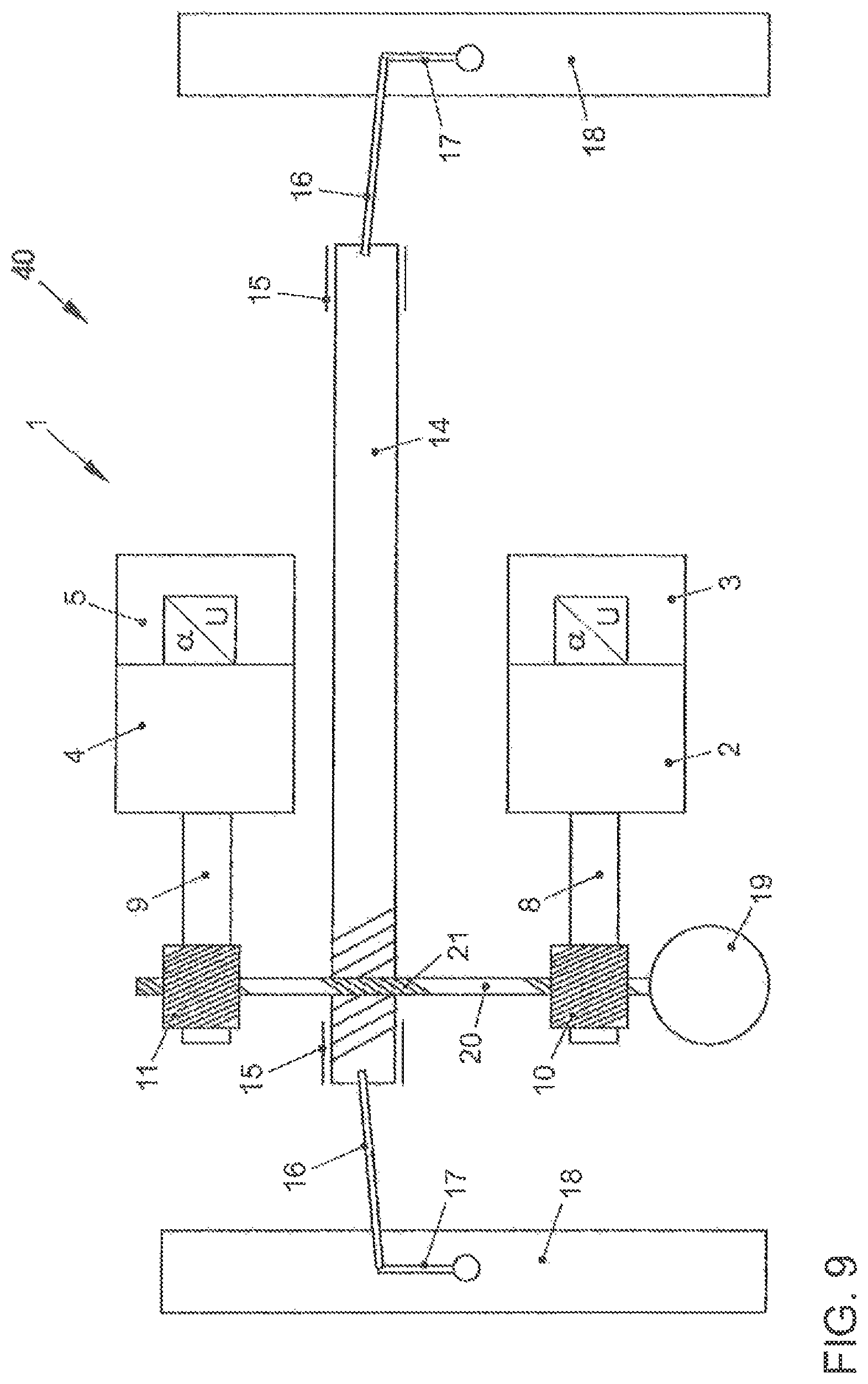
FIG. 9 shows an electromechanical steering with a servomotor on the steering column and a servomotor in the engine compartment in a first disclosed embodiment;
FIG. 10 shows an electromechanical steering with a servomotor on the steering column and a servomotor in the engine compartment in a second disclosed embodiment;
FIG. 11 shows an electromechanical steering with a servomotor on the steering column and a servomotor in the engine compartment in a third disclosed embodiment; and
FIG. 12 shows a schematic representation of a double motor.
DETAILED DESCRIPTION OF THE DISCLOSED EMBODIMENTS
Driver assistance systems are increasingly being used to help a vehicle driver guide a motor vehicle. The increase in such systems takes the form of partially, highly or fully automatic guiding of a motor vehicle, where the driver of the motor vehicle does not perform any steering or braking actions but instead the motor vehicle drives automatically. This gives rise to the problem that, when switching back from automatic guiding of the motor vehicle to driver-guided driving, the driver of the motor vehicle requires a certain amount of time to resume full control. In particular, individual faults should therefore not lead to the system being abruptly switched off. On the other hand, expenditure on additional parts should not be increased unnecessarily.
The illustrative embodiments address the technical problem of providing a device for assisting or automatic guiding of a motor vehicle in which the automatic or assisting steering movement is ensured more dependably.
For this purpose, the device for assisting or automatic guiding of a motor vehicle comprises a first steering actuator with an assigned steering control unit, a gear rack, a steering column and a steering handle, the steering column and the steering actuator having an effect on the common gear rack, wherein there is at least a second steering actuator with a further assigned steering control unit, the second steering actuator having an effect on the common gear rack.
Disclosed embodiments are based on the fact that conventional steering systems are formed with only a single mechanical circuit, i.e. there is only one steering handle, one steering column and one steering gear and, moreover, the two wheels on the right and left are mechanically connected to one another in a fixed manner by way of the steering lever arms of the swivel bearings, the track rods and the gear rack. It is assumed here that by providing adequate dimensioning, using metallic or similar materials for production and conducting adequate tests on test benches or during driving operation, redundancy of these mechanical components becomes unnecessary. Therefore, only the steering actuator with its assigned steering control unit is redundantly formed, but not the gear rack, the steering handle and the steering column. Optionally, the respective steering actuator is also assigned sensors of its own for sensing actual values. In this case, the two steering control units receive their setpoint values through a higher-level control unit for assisting or automatic guiding of a motor vehicle, wherein the data connection between the higher-level control unit and the steering control units may take place by way of separate bus systems, so that here too there is a redundancy to compensate for single faults. Again, the two steering control units may be directly connected to one another by way of a further bus system, so that if there is a fault of one bus system, the steering control unit assigned to the bus system can receive its setpoint values by way of the other bus system and the further bus system and can transmit its actual values to the higher-level control unit by way of the further bus system and the other bus system.
In a further disclosed embodiment, the two steering actuators are formed as electrical servomotors which are connected to electrical energy supply units that are independent of one another. For example, the two energy supply units are formed as batteries which are connected to a common generator or a common high-voltage battery by way of diodes, the diodes preventing a return effect. Instead of the diodes, other components that ensure a directed current flow may also be used.
Optionally, the two servomotors are identically formed, wherein the two servomotors can be put into operation in parallel or one after the other. For example, the two servomotors are designed for a maximum torque of 3 Nm. With only one servomotor, it is possible in the event of a fault to continue steering during driving with reduced maximum dynamics. Only during parking when stationary, when the greatest torques are required, is the individual servomotor unable to cope. Indeed, until now the driver has usually resumed control. Automatically parking vehicles on the other hand simply remain stationary. In any event, a single fault of a servomotor does not lead to a critical situation.
Optionally, the two servomotors are formed as brushless servomotors. This provides advantages in terms of durability, since there are no longer any brushes that undergo wear. The two servomotors may be formed as direct-current, rotary-current or alternating-current motors, in at least one disclosed embodiment one servomotor being formed as a synchronous motor and the other servomotor being formed as an asynchronous motor.
For commutating the two servomotors, there are necessarily two angle sensors or resolvers. Since the motor angle is then redundantly available, a separate steering wheel angle sensor of an electronic stability program can be replaced. Optionally, the two servomotors are fitted in such a way that they are slightly rotated in relation to one another. Each electric motor has, depending on its number of poles and the magnetic design, so-called cogging torques. When the rotor is released, it moves into a position where the cogging torque is at a maximum. The slightly rotated arrangement of the servomotors allows the number of cogging points to be doubled, and the cogging torques become less. This allows a more uniform torque profile to be achieved.
The connection of the two servomotors can in this case be performed in various ways, components that have been found from experience in the field with electrical power-assisted steering systems to have no probability of failure or only an extremely small probability also may be fitted only singly.
In at least one disclosed embodiment, the two electrical servomotors are connected to the common gear rack by way of a steering pinion of their own in each case. The two steering pinions of the two servomotors may be fitted closely to one another, so that the toothing only has to be extended slightly.
In another disclosed embodiment, the two servomotors are connected to the gear rack by way of a common steering pinion, whereby one steering pinion is saved and the toothing of the gear rack does not have to be extended. This also can be realized by various disclosed embodiments.
In at least one disclosed embodiment, the two servomotors act on different sides of the common steering pinion.
In another disclosed embodiment, the two servomotors are seated on a common shaft.
In a further disclosed embodiment, the shafts of the servomotors are connected to a steering pinion by a common driver, the steering pinion being connected to the gear rack.
In a further disclosed embodiment, the two servomotors are connected to the gear rack by way of a recirculating ball gear with a belt drive. This disclosed embodiment may be used in the case of axially parallel steering systems; again the belt drive may be doubled. In this case, the nut of the recirculating ball gear is designed to be wider, so that two belt drives can circulate, a belt drive being respectively connected to a servomotor. For the symmetrical loading of the recirculating ball gear, one of the two belts may also be divided into two narrow belts, which are then arranged on the outside of the recirculating ball gear and are connected to a servomotor, while a wider belt that is connected to the other servomotor is arranged between the two narrow belts. There is consequently redundancy with respect to the motors and the drives. Alternatively, both servomotors may be located on a common shaft and the belt drive is doubled.
In a further disclosed embodiment, one electrical servomotor is arranged on the steering column and the other electrical servomotor is arranged in the engine compartment. Electrical servomotors on the steering column in the passenger compartment of the vehicle are also referred to as column EPS systems. The electrical servomotor in the engine compartment is also fitted as a so-called single-pinion EPS and shares with the steering column a common steering pinion for the conversion of the rotary movement of the steering column into a translational movement of the gear rack. Alternatively, the servomotor in the engine compartment and the steering column may also have a steering pinion of their own in each case. In a further disclosed embodiment, the servomotor in the engine compartment and the steering column share a common steering pinion, whereas the servomotor on the steering column is coupled to the gear rack by way of a steering pinion of its own.
In a further disclosed embodiment, the two servomotors are formed as double motors which are arranged in a common housing, wherein permanent magnets are fixedly arranged, optionally adhesively bonded, on a common rotor shaft and the windings of the two servomotors are arranged alternately on the stator side. In addition, two motor angle sensors are fitted. As a result, many common parts that are considered not to be susceptible to faults are used. Only one steering pinion is required and the motor mounting can be retained as in the case of conventional steering systems with only one servomotor.
In FIG. 1, an electromechanical steering is schematically represented as part of a device 1 for assisting or automatic guiding of a motor vehicle. The device 1 comprises a first steering actuator 2 with an assigned steering control unit 3 and also a second steering actuator 4 with an assigned steering control unit 5. In this case, the first steering control unit 3 is connected to a first bus system 6 and the second steering control unit 5 is connected to a second bus system 7. Furthermore, the two steering control units 3, 5 are directly connected to one another by way of a further bus system (not represented for reasons of overall clarity). By way of the bus systems 6, 7, the steering control units 3, 5 receive setpoint values for the steering actuators 2, 4 from at least one high-level control unit for the assisting or automatic guiding of the motor vehicle. Similarly, actual values can be transmitted from the steering control units 3, 5 by way of the bus systems 6, 7 to the higher-level control unit. By way of the further bus system directly between the steering control units 3, 5, these can set up a redundant communication, in that for example setpoint values for the first steering control unit 3 are also transmitted by way of the second bus system 7 and the further bus system to the first steering control unit 3, so that the latter receives its setpoint values over two paths. This can be used for all transmissions of information, such as for example the setpoint values of the second steering control unit and also the actual values of the first and second steering actuators 2, 4. In the control units 3, 5, a setpoint steering angle .alpha. set is converted into an actual revolution U of a shaft 8, 9 of the respective steering actuator 2, 4. The steering actuators 2, 4 may be in this case formed as electrical servomotors. A motor pinion 10 is arranged on the shaft 8 and a motor pinion 11 is arranged on the shaft 9. Respective steering pinions 12, 13, which are in engagement with a gear rack 14, are connected to the respective motor pinions 10, 11. The gear rack 14 is held by way of bearings 15 and at its end has track rods 16, which are connected to swivel lever arms 17 of the swivel bearings that are connected to the wheels 18. Furthermore, connected to a steering column 20 is a steering handle 19, at the free end of which there is arranged a further steering pinion 21, which is likewise in engagement with the gear rack 14. Here, too, a conversion takes place between the steering angle .alpha. steering wheel and the revolution U of the steering column 20. In the event of a single fault of a steering actuator 2, 4 or its assigned elements, there is still half of the steering power available, so that the motor vehicle remains dependably controllable up until the time it is taken over by the driver of the motor vehicle.
In FIG. 2, a disclosed embodiment is represented, wherein the same elements are provided with the same reference numerals, the bus systems 6, 7 no longer being represented in this and the other disclosed embodiments. The only difference from the disclosed embodiment according to FIG. 1 is that now the two motor pinions 10, 11 are connected to a common steering pinion 22, these motor pinions acting on different sides of the steering pinion 22. If it is assumed that the common steering pinion 22 is constructed similarly robustly as the gear rack 14, a steering pinion along with its mounting is saved in comparison with FIG. 1, the same applying with regard to single faults as stated in relation to FIG. 1. A further advantage is that a toothing 23 of the gear rack 14 does not have to be extended.
In FIG. 3, a further disclosed embodiment is represented, wherein the two steering actuators 2, 4 that are formed as servomotors are seated on a common shaft 24 with a motor pinion 25.
In FIGS. 4 and 5, a further disclosed embodiment is represented, wherein the two motor shafts 8, 9 are connected to the steering pinions 26, 27 by way of a screw gear. The steering pinion 27 is in engagement with the gear rack 14.
In FIG. 6, a further disclosed embodiment is represented, wherein, in comparison with FIG. 2, the common steering pinion 22 has been replaced by a common recirculating ball gear 28 and the motor pinions 10, 11 are no longer needed. For reasons of symmetry, the shaft 8 of the first steering actuator 2 is connected to the recirculating ball gear 28 by two narrow outer belt drives 29, 30. The shaft 9 of the second steering actuator 4 is connected to the recirculating ball gear 28 by way of a wider central belt drive 31.
In FIGS. 7 and 8, a disclosed embodiment with a recirculating ball gear 28 is represented, where the two steering actuators 2, 4 are respectively seated on a common shaft 24, which is connected to the recirculating ball gear 28 by way of a double belt drive 32, 33.
In FIG. 9, a further disclosed embodiment is represented, wherein the first steering actuator 2 is arranged on the steering column 20 and the second steering actuator 4 is arranged in the engine compartment 40. In this case, the motor pinion 10 acts on a toothing of the steering column 20, whereas the motor pinion 11 is connected to the steering pinion 21 of the steering column 20.
Alternatively, the motor pinion 11 may be connected to the gear rack 14 by way of a steering pinion 13 of its own, which is represented in FIG. 10.
Finally, in FIG. 11, a further disclosed embodiment is represented, wherein the steering actuator 2 is connected to the gear rack 14 by way of a steering pinion 12 of its own, whereas the second steering actuator 4 acts with its motor pinion 11 on the common steering pinion 21 of the steering column 20.
In FIG. 12, a double motor 35 is schematically represented. Permanent magnets that are not represented are adhesively bonded on a common rotor shaft 36, wherein the windings 38, 39 of the first steering actuator 2 and of the second steering actuator 4 are arranged in an alternating segmental manner on the stator 37, only the windings 38, 39 for one segment being respectively represented.
LIST OF REFERENCE NUMERALS
1 Device 2 Steering actuator 3 Steering control unit 4 Steering actuator 5 Steering control unit 6 Bus system 7 Bus system 8 Shaft 9 Shaft 10 Motor pinion 11 Motor pinion 12 Steering pinion 13 Steering pinion 14 Gear rack 15 Bearing 16 Track rod 17 Swivel lever arm 18 Wheels 19 Steering handle 20 Steering column 21 Steering pinion 22 Steering pinion 23 Toothing 24 Shaft 25 Motor pinion 26 Steering pinion 27 Steering pinion 28 Recirculating ball gear 29 Belt drive 30 Belt drive 31 Belt drive 32 Belt drive 33 Belt drive 35 Double motor 36 Rotor shaft 37 Stator 38 Winding 39 Winding
* * * * *
D00000
D00001
D00002
D00003
D00004
D00005
D00006
D00007
D00008
D00009
D00010
D00011
D00012

XML
uspto.report is an independent third-party trademark research tool that is not affiliated, endorsed, or sponsored by the United States Patent and Trademark Office (USPTO) or any other governmental organization. The information provided by uspto.report is based on publicly available data at the time of writing and is intended for informational purposes only.
While we strive to provide accurate and up-to-date information, we do not guarantee the accuracy, completeness, reliability, or suitability of the information displayed on this site. The use of this site is at your own risk. Any reliance you place on such information is therefore strictly at your own risk.
All official trademark data, including owner information, should be verified by visiting the official USPTO website at www.uspto.gov. This site is not intended to replace professional legal advice and should not be used as a substitute for consulting with a legal professional who is knowledgeable about trademark law.