Soft suture anchor assembly with barbed suture and attached tissue fixation disk
Dreyfuss J
U.S. patent number 10,524,776 [Application Number 15/345,952] was granted by the patent office on 2020-01-07 for soft suture anchor assembly with barbed suture and attached tissue fixation disk. This patent grant is currently assigned to Arthrex, Inc.. The grantee listed for this patent is Arthrex, Inc.. Invention is credited to Peter J. Dreyfuss.

| United States Patent | 10,524,776 |
| Dreyfuss | January 7, 2020 |
Soft suture anchor assembly with barbed suture and attached tissue fixation disk
Abstract
A suture anchor assembly and a method of tissue repair using the assembly. The assembly includes a soft suture anchor formed of a flexible tubular sheath with opposing open ends which receives a suture strand from a suture construct. The suture strand has a tensioning free end and an opposite tissue-fixation end. A tissue-fixation device, such as a disk, is coupled to the tissue-fixation end of the suture strand. The suture strand has uni-directional barbs which allow one-way tensioning, to provide secure fixation of soft tissue to bone as the strand is pulled through the sheath of the soft anchor.
| Inventors: | Dreyfuss; Peter J. (Naples, FL) | ||||||||||
|---|---|---|---|---|---|---|---|---|---|---|---|
| Applicant: |
|
||||||||||
| Assignee: | Arthrex, Inc. (Naples,
FL) |
||||||||||
| Family ID: | 60262813 | ||||||||||
| Appl. No.: | 15/345,952 | ||||||||||
| Filed: | November 8, 2016 |
Prior Publication Data
| Document Identifier | Publication Date | |
|---|---|---|
| US 20180125472 A1 | May 10, 2018 | |
| Current U.S. Class: | 1/1 |
| Current CPC Class: | A61F 2/0811 (20130101); A61B 17/0401 (20130101); A61B 2017/0409 (20130101); A61B 2017/0414 (20130101); A61B 2017/06176 (20130101); A61B 2017/0424 (20130101); A61B 2017/0404 (20130101); A61B 2017/0462 (20130101); A61B 2017/0406 (20130101); A61B 2017/0464 (20130101); A61F 2002/0888 (20130101); A61B 2017/0412 (20130101); A61B 2017/0496 (20130101) |
| Current International Class: | A61B 17/04 (20060101) |
References Cited [Referenced By]
U.S. Patent Documents
| 5370661 | December 1994 | Branch |
| 5372146 | December 1994 | Branch |
| 5520691 | May 1996 | Branch |
| 5645568 | July 1997 | Chervitz |
| 5725556 | March 1998 | Moser |
| 5814056 | September 1998 | Prosst |
| 6027523 | February 2000 | Schmieding |
| 6485504 | November 2002 | Johnson |
| 6620185 | September 2003 | Harvie |
| 7144414 | December 2006 | Harvie |
| 7144415 | December 2006 | Del Rio |
| 7410460 | August 2008 | Benderev |
| 7442202 | October 2008 | Dreyfuss |
| 7572275 | August 2009 | Fallin |
| 7582105 | September 2009 | Kolster |
| 7785347 | August 2010 | Harvie |
| 7959650 | June 2011 | Kaiser |
| 8088130 | January 2012 | Kaiser |
| 8118836 | February 2012 | Denham |
| 8231654 | July 2012 | Kaiser |
| 8414612 | April 2013 | Kirsch et al. |
| 8562647 | October 2013 | Kaiser |
| 8608777 | December 2013 | Kaiser |
| 8652172 | February 2014 | Denham |
| 8663277 | March 2014 | Collier et al. |
| 8721664 | May 2014 | Ruff et al. |
| 8747438 | June 2014 | Longo |
| 8795334 | August 2014 | Astorino et al. |
| 8814904 | August 2014 | Bennett |
| 8932327 | January 2015 | Kosa et al. |
| 8979895 | March 2015 | Miller |
| 8986346 | March 2015 | Dreyfuss |
| 9011487 | April 2015 | Lindh, Sr. |
| 9271706 | March 2016 | Stopek |
| 9307979 | April 2016 | Bennett |
| 9345567 | May 2016 | Sengun |
| 9357992 | June 2016 | Stone et al. |
| 9463011 | October 2016 | Dreyfuss et al. |
| 9480473 | November 2016 | Kim |
| 9532777 | January 2017 | Kaiser |
| 9597068 | March 2017 | Sengun |
| 9700305 | July 2017 | Bennett |
| 9757122 | September 2017 | Bennett |
| 9833234 | December 2017 | Broom |
| 9855033 | January 2018 | Bennett |
| 9861351 | January 2018 | Kaiser |
| 9924937 | March 2018 | Kim |
| 9962150 | May 2018 | Rodriguez |
| 10004489 | June 2018 | Kaiser |
| 10039543 | August 2018 | Durando |
| 10058320 | August 2018 | Oren |
| 2003/0078585 | April 2003 | Johnson |
| 2003/0149447 | August 2003 | Morency et al. |
| 2004/0049194 | March 2004 | Harvie |
| 2005/0267531 | December 2005 | Ruff et al. |
| 2006/0122608 | June 2006 | Fallin |
| 2007/0038249 | February 2007 | Kolster |
| 2008/0312689 | December 2008 | Denham |
| 2009/0082805 | March 2009 | Kaiser |
| 2009/0182375 | July 2009 | Isse |
| 2009/0312776 | December 2009 | Kaiser |
| 2010/0036395 | February 2010 | Miller |
| 2010/0087854 | April 2010 | Stopek |
| 2010/0160963 | June 2010 | Fallin |
| 2010/0298871 | November 2010 | Ruff et al. |
| 2011/0054522 | March 2011 | Lindh, Sr. |
| 2011/0213416 | September 2011 | Kaiser |
| 2012/0041485 | February 2012 | Kaiser |
| 2012/0290003 | November 2012 | Dreyfuss |
| 2013/0296934 | November 2013 | Sengun |
| 2014/0081325 | March 2014 | Sengun |
| 2014/0121700 | May 2014 | Dreyfuss et al. |
| 2014/0194927 | July 2014 | Kaiser |
| 2014/0249577 | September 2014 | Pilgeram |
| 2014/0316460 | October 2014 | Graul et al. |
| 2014/0364862 | December 2014 | Bennett |
| 2014/0364904 | December 2014 | Kim |
| 2015/0051642 | February 2015 | Broom |
| 2015/0173739 | June 2015 | Rodriguez |
| 2015/0173754 | June 2015 | Norton et al. |
| 2015/0257750 | September 2015 | Kaiser |
| 2015/0351740 | December 2015 | Bennett |
| 2015/0351759 | December 2015 | Bennett |
| 2016/0051246 | February 2016 | Durando |
| 2016/0135797 | May 2016 | Stopek |
| 2016/0174963 | June 2016 | Oren |
| 2016/0242760 | August 2016 | Kaiser |
| 2016/0310130 | October 2016 | Pilgeram |
| 2017/0035411 | February 2017 | Kaiser |
| 2017/0042531 | February 2017 | Kim |
| 2017/0143329 | May 2017 | Sengun |
| 2017/0325802 | November 2017 | Bennett |
| 2018/0116661 | May 2018 | Bennett |
| 2018/0125472 | May 2018 | Dreyfuss |
| 2018/0125476 | May 2018 | Kaiser |
| 2018/0153538 | June 2018 | Kaiser |
| 2018/0168567 | June 2018 | Kim |
| 2018/0228484 | August 2018 | Rodriguez |
| 2 774 545 | Sep 2014 | EP | |||
| WO 2014/031578 | Feb 2014 | WO | |||
Attorney, Agent or Firm: Blank Rome LLP
Claims
What is claimed is:
1. A method of tissue repair, comprising the steps of: loading a soft anchor with a suture construct including a suture strand passing through a tubular sheath of the soft anchor, the suture strand having a tensioning free end and an opposite tissue-fixation end, a tissue-fixation device coupled to the tissue-fixation end of the suture strand, and a locking structure disposed on the suture strand; passing the pre-loaded soft anchor through tissue; installing the pre-loaded soft anchor in a hole formed in bone; and pulling the tensioning free end of the suture strand to draw the tissue-fixation device against the tissue to approximate the tissue to bone and draw at least a portion of the locking structure into the tubular sheath of the soft anchor, thereby locking the suture construct in place.
2. A method according to claim 1, wherein, when the soft anchor is passed through the tissue, the tensioning free end and the tissue-fixation end of the suture strand remain and are not passed through the tissue.
3. A method according to claim 1, wherein pulling the tensioning free end of the suture strand pulls the locking structure through the tissue.
4. A method according to claim 3, wherein the locking structure includes barbs that angle outwardly in a direction toward the tissue-fixation device to facilitate passage of the locking structure through the tissue and facilitate a one-way locking engagement with the tubular sheath of the soft anchor.
5. A method according to claim 1, wherein the step of passing the pre-loaded soft anchor through tissue includes passing the pre-loaded soft anchor through a guide that was previously passed through the tissue.
6. A method according to claim 5, further comprising the step of removing the guide once the soft anchor is installed in the hole formed in bone.
7. A method according to claim 6, wherein the guide includes an elongated slot to facilitate removal of the guide without interfering with the suture construct.
8. A method according to claim 1, wherein the soft anchor is installed into the hole formed in bone by capturing the tubular sheath of the soft anchor with an inserter and malleting the inserter to advance the soft anchor into the hole.
9. A method according to claim 1, further comprising the step of overmolding the locking structure on the tissue-fixation end of the suture strand.
10. A method according to claim 1, wherein the suture strand is passed through open ends of the tubular sheath.
11. A method according to claim 1, wherein the step of pulling the tensioning free end includes pulling a loop on the tensioning free end of the suture strand.
Description
FIELD OF THE INVENTION
The present invention relates to a suture anchor assembly used for attachment of tissue to bone, and more particularly to a soft suture anchor assembly with a barbed suture and an attached tissue fixation disk.
BACKGROUND OF THE INVENTION
Various types of suture anchors have been developed for securing soft tissue to bone. U.S. Pat. No. 6,027,523 to Schmieding and U.S. Pat. No. 7,442,202 to Dreyfuss, both of which are herein incorporated by reference, disclose a tissue repair method using a rigid anchor structure with a driving end for creating a hole in bone and an opposing disk for capturing the soft tissue. A need exists for a simplified anchor solution used in soft tissue repair that sufficiently fixes the soft tissue to bone and locks the same in place.
SUMMARY OF THE INVENTION
Accordingly, the present invention provides a suture anchor assembly that comprises a soft suture anchor and a suture construct for fixation of soft tissue to bone. The soft suture anchor is formed of a flexible tubular sheath with opposing open ends, and receives a suture strand that forms parts of a suture construct. The suture strand has a tensioning free end and an opposite tissue-fixation end. A tissue-fixation structure, such as a mesh disk or button, is attached to the tissue-fixation end of the suture strand. A locking structure, such as a plurality of uni-directional barbs, is disposed on at least a portion of the suture strand between the tensioning free and tissue-fixation ends thereof.
The present invention may also provide a method of tissue repair, comprising the steps of loading a soft anchor with a suture construct including a suture strand passing through a tubular sheath of the soft anchor, the suture strand having a tensioning free end and an opposite tissue-fixation end, a tissue-fixation device, such as a mesh disk or button, coupled to the tissue-fixation end of the suture strand, and a locking structure, such as barbs, disposed on the suture strand; passing the pre-loaded soft anchor through tissue; installing the pre-loaded soft anchor in a hole formed in bone; and pulling the tensioning free end of the suture strand to draw the disk against the tissue to approximate the tissue to bone and draw at least a portion of the barbs into the tubular sheath of the soft anchor thereby locking the suture construct in place.
BRIEF DESCRIPTION OF THE DRAWINGS
A more complete appreciation of the invention and many of the attendant advantages thereof will be readily obtained as the same becomes better understood by reference to the following detailed description when considered in connection with the accompanying drawing figures:
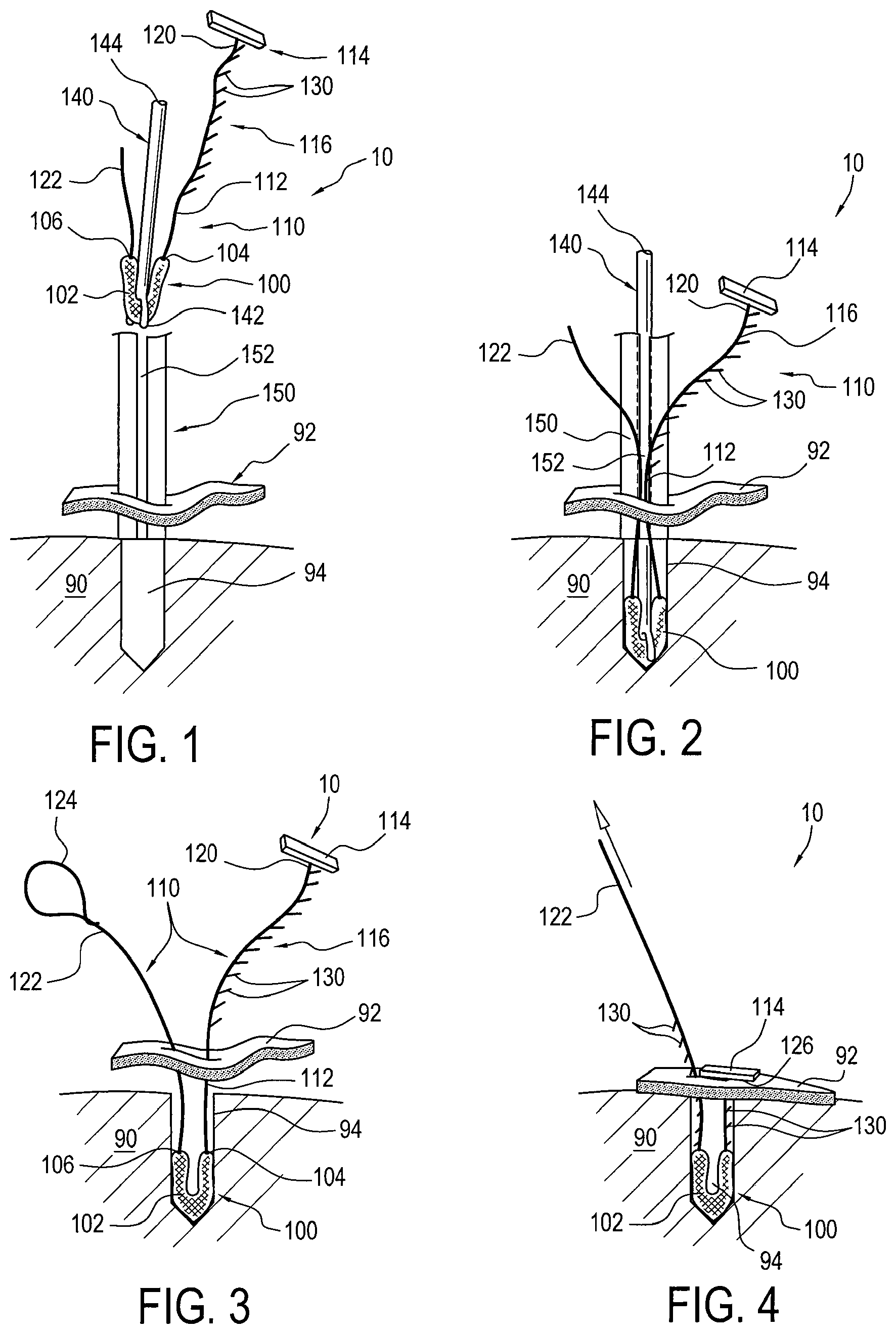
FIG. 1 is a schematic elevational view of a suture anchor assembly according to an exemplary embodiment of the present invention, showing the suture anchor assembly being inserted via an inserter into a guide located over a bone hole in accordance with a method of tissue repair of the present invention;
FIG. 2 is a schematic elevational view similar to FIG. 1 showing a soft anchor of the suture anchor assembly and an end of the inserter received in the bone hole after the step of FIG. 1, in accordance with the method of tissue repair;
FIG. 3 is a schematic elevational view similar to FIG. 2 showing the inserter and guide removed after the step of FIG. 2 in accordance with the method of tissue repair; and
FIG. 4 is a schematic elevational view similar to FIG. 3 showing the tissue fixed to bone and the suture anchor assembly locked in place after the step of FIG. 2 in accordance with the method of tissue repair.
DETAILED DESCRIPTION OF THE PREFERRED EMBODIMENTS
Referring to FIGS. 1-4, a suture anchor assembly 10 for tissue fixation is provided in accordance with an exemplary embodiment of the present. The suture anchor assembly 10 of the present invention provides for a simplified tissue repair while also ensuring positive fixation of the tissue to bone.
Suture anchor assembly 10 generally includes a soft suture anchor 100 and a suture construct 110 coupled thereto. Soft suture anchor 100 may include a tubular sheath 102, such as disclosed in commonly assigned U.S. Pat. No. 9,463,011 to Dreyfuss et al., the subject matter of which is herein incorporated by reference, made of flexible material, such as polyester or the like. Tubular sheath 102 may be a woven, braided, or knitted structure, and/or may be formed of yarns, fibers, filaments, sutures or similar materials, or combinations of these materials. Tubular sheath 102 has opposing open ends 104 and 106 through which suture construct 110 may extend.
Suture construct 110 may generally include a flexible suture strand 112, a tissue-fixation device 114, and a locking structure 116. Strand 112 has a tissue-fixation end 120 and an opposite tensioning free end 122. Tissue-fixation end 120 preferably extends through opening 104 of tubular sheath 102 and tensioning free end 122 preferably extends through opening 106. Tissue-fixation end 120 and tensioning free end 122 of strand 112 may also extend through respective openings in the length of tubular sheath 102 near or spaced from ends 104 and 106, as disclosed in U.S. Pat. No. 9,463,001 to Dreyfuss et al. Tensioning free end 122 may include a loop or eyelet 124 (FIG. 3) to assist in pulling suture strand 112.
Tissue-fixation device 114 is preferably coupled to tissue-fixation end 120 of strand 112 by any known attachment, such as tying or adhering the strand 112 to device 114. Tissue fixation device 114 preferably has a disk or button shape and may be formed of any biocompatible material. Tissue-fixation device 114 may have other shapes, such as ring, straight or bended bar, cross and the like. Tissue-fixation device 114 may be generally solid, such as a polymer, or may be flexible, such as a mesh. Tissue-fixation device 114 includes a surface area 126 for abutting against tissue, as best seen in FIG. 4.
Locking structure 116 is provided on flexible strand 112 to prevent loosening of the suture construct 110 once tissue 92 is secured against the bone 90. Locking structure 116 is preferably configured to provide a one-way lock. The one-way lock of locking structure 116 may be created, for example, using one or more uni-directional barbs 130. As seen in the figures, these barbs 130 preferably angle outwardly in a direction toward tissue-fixation device 114. The one or more barbs 130 may be provided on a portion of suture strand 112, preferably a portion of suture strand 112 that is closer to the tissue-fixation end 120 than the tensioning free end 122. Alternatively, barbs 130 may be provided continuously or discontinuously along the length of suture strand 112. And the barbs 130 may extend from one or more sides or areas of suture strand 112. In a preferred embodiment, the barbs 130 are overmolded onto suture strand 112.
A method of tissue repair using the suture anchor assembly 10 of the present invention generally includes the steps of passing suture anchor assembly 10 through the tissue 92, as seen in FIGS. 1 and 2, then installing soft anchor 100 of assembly 10 into a hole/socket of the bone 90, as seen in FIG. 2, and finally pulling suture strand 112 to draw tissue-fixation device 114 against the tissue 92 to secure the tissue 92 against the bone 90.
More specifically, the method may include the initial step of loading soft anchor 100 with suture construct 110 by passing tensioning free end 122 of suture strand 112 through tubular sheath 102 such that tissue-fixation end 120 of strand 112 extends through sheath opening 104 and tensioning free end 122 extends through sheath opening 106. Alternatively, tissue-fixation end 120 and tensioning free end 122 may extend through respective openings in the length of tubular sheath 102 near or spaced from ends 104 and 106.
Soft anchor 100 pre-loaded with suture construct 110 is passed through the tissue 92 and installed into a pre-drilled hole/socket 94 of the bone 90. For optimal installation of suture construct assembly 10, an inserter 140 and a guide 150 are preferably used, as best seen in FIGS. 1 and 2. Inserter 140 includes an end 142, such as a forked tip, that is designed to capture soft anchor 100. Once the end 142 of inserter 140 captures soft anchor 100, soft anchor 100 along with suture construct 110 may be pushed through guide 150 which has been inserted through the tissue 90 and positioned over the pre-drilled hole 94 in the bone 90, as seen in FIG. 1. This facilitates installation of soft anchor 100 into the bone hole 94. To assist with the advancement and installation of soft anchor 100 into the bone hole 94, an impact or mallet tool may be applied to the opposite end 144 of inserter 140. Insertion of soft anchor 100 into bone hole 94, as seen in FIG. 2 preferably forms a tight fit to anchor soft anchor 100 therein. When received in the bone hole 94, tubular sheath 102 preferably bunches up within the bone hole 94 in a similar manner as disclosed in U.S. Pat. No. 9,463,001 to Dreyfuss et al. That is, soft anchor 100 may be inserted in a doubled over manner so that the ends of tubular sheath 102 are following its middle portion once set in bone, such that when tension is pulled on the suture construct 110, the soft anchor 100 bunches up to take up more room in bone hole 94 and therefore fixes in place. Also, the material of tubular sheath 102, such as a braid, may assist with anchoring of soft anchor 100 because of its loose composition together with the trabecular cancellous nature of the bone creates a fixation therebetween.
Once soft anchor 100 is installed in bone hole 94, inserter 140 and guide 150 may be removed. In a preferred embodiment, guide 150 includes an elongated slot 152 along its length, as best in FIG. 1, which allows suture strand 112 to escape and thus not interfere with the guide's removal. As seen in FIG. 3, once soft anchor 100 is installed in bone hole 94, tissue-fixation end 120 of strand 112 with tissue fixation device 114 and tensioning free end 122 remain outside of bone hole 94. That is, when soft anchor 100 preloaded with suture construct 110 is passed through the tissue 92, the tissue-fixation and tensioning free ends 120 and 122 remain and are not passed through the tissue 92.
As seen in FIG. 4, tensioning free end 122 of suture strand 112 may then be pulled away from the bone 90 in a tightening direction to pull strand 112 through tubular sheath 102 of soft anchor 100 and draw tissue-fixation device against the tissue 92. The uni-directional nature of barbs 130 allows the suture strand 112 and locking structure 116 to be pulled, via tensioning free end 122, unobstructed in one direction, that is, in the tightening direction, through the tissue 92 and tubular sheath 102, while preventing the strand 112 from moving in the opposite direction, that is, in the loosening direction. Tissue-fixation device 114, and particularly its surface area 126, applies a compressive force to the tissue 92 as strand 112 is being pulled to approximate the tissue 92 to bone 90. Barbs 130 engage tubular sheath 102 to lock suture construct 110 in place to secure the attachment of the tissue 92 to the bone 90. The uni-directional nature and angle of barbs 130 prevents tissue-fixation device 114 or strand 112 from loosening.
While particular embodiments have been chosen to illustrate the invention, it will be understood by those skilled in the art that various changes and modifications can be made therein without departing from the scope of the invention as defined in the appended claims.
* * * * *
D00000
D00001
XML
uspto.report is an independent third-party trademark research tool that is not affiliated, endorsed, or sponsored by the United States Patent and Trademark Office (USPTO) or any other governmental organization. The information provided by uspto.report is based on publicly available data at the time of writing and is intended for informational purposes only.
While we strive to provide accurate and up-to-date information, we do not guarantee the accuracy, completeness, reliability, or suitability of the information displayed on this site. The use of this site is at your own risk. Any reliance you place on such information is therefore strictly at your own risk.
All official trademark data, including owner information, should be verified by visiting the official USPTO website at www.uspto.gov. This site is not intended to replace professional legal advice and should not be used as a substitute for consulting with a legal professional who is knowledgeable about trademark law.