Wearable inward-facing camera utilizing the Scheimpflug principle
Tzvieli , et al. Dec
U.S. patent number 10,523,852 [Application Number 15/722,434] was granted by the patent office on 2019-12-31 for wearable inward-facing camera utilizing the scheimpflug principle. This patent grant is currently assigned to Facense Ltd.. The grantee listed for this patent is Facense Ltd.. Invention is credited to Ari M Frank, Gil Thieberger, Arie Tzvieli.


View All Diagrams
| United States Patent | 10,523,852 |
| Tzvieli , et al. | December 31, 2019 |
Wearable inward-facing camera utilizing the Scheimpflug principle
Abstract
One aspect of this disclosure involves a wearable device that includes a frame that is worn on a user's head, and an inward-facing camera (camera) physically coupled to the frame. The optical axis of the camera is either above the Frankfort horizontal plane and pointed upward to capture an image of a region of interest (ROI) above the user's eyes, or the optical axis is below the Frankfort horizontal plane and pointed downward to capture an image of an ROI below the user's eyes. The camera includes a sensor and a lens. The sensor plane is tilted by more than 2.degree. relative to the lens plane according to the Scheimpflug principle in order to capture a sharper image. The Scheimpflug principle is a geometric rule that describes the orientation of the plane of focus of a camera when the lens plane is tilted relative to the sensor plane.
| Inventors: | Tzvieli; Arie (Berkeley, CA), Thieberger; Gil (Kiryat Tivon, IL), Frank; Ari M (Haifa, IL) | ||||||||||
|---|---|---|---|---|---|---|---|---|---|---|---|
| Applicant: |
|
||||||||||
| Assignee: | Facense Ltd. (Kiryat Tivon,
IL) |
||||||||||
| Family ID: | 60989012 | ||||||||||
| Appl. No.: | 15/722,434 | ||||||||||
| Filed: | October 2, 2017 |
Prior Publication Data
| Document Identifier | Publication Date | |
|---|---|---|
| US 20180027158 A1 | Jan 25, 2018 | |
Related U.S. Patent Documents
| Application Number | Filing Date | Patent Number | Issue Date | ||
|---|---|---|---|---|---|
| 15284528 | Oct 3, 2016 | 10113913 | |||
| 15231276 | Aug 8, 2016 | ||||
| 15182592 | Jun 14, 2016 | 10165949 | |||
| 62480496 | Apr 2, 2017 | ||||
| 62456105 | Feb 7, 2017 | ||||
| 62408677 | Oct 14, 2016 | ||||
| 62372063 | Aug 8, 2016 | ||||
| 62354833 | Jun 27, 2016 | ||||
| 62236868 | Oct 3, 2015 | ||||
| 62202808 | Aug 8, 2015 | ||||
| 62175319 | Jun 14, 2015 | ||||
| Current U.S. Class: | 1/1 |
| Current CPC Class: | G02B 27/0176 (20130101); G01J 5/0025 (20130101); A61B 5/163 (20170801); H04N 5/33 (20130101); A61B 5/6814 (20130101); A61B 5/6803 (20130101); A61B 5/0075 (20130101); H04N 5/2254 (20130101); A61B 5/165 (20130101); G02B 27/0172 (20130101); G06N 20/00 (20190101); A61B 5/015 (20130101); G02B 2027/0138 (20130101); A61B 5/0077 (20130101); A61B 2562/0271 (20130101); G06N 3/0445 (20130101) |
| Current International Class: | H04N 5/33 (20060101); G02B 27/01 (20060101); H04N 5/225 (20060101) |
References Cited [Referenced By]
U.S. Patent Documents
| 5143086 | September 1992 | Duret et al. |
| 5664578 | September 1997 | Boczan |
| 6121953 | September 2000 | Walker |
| 6286958 | September 2001 | Koest et al. |
| 6771423 | August 2004 | Geist |
| 6837615 | January 2005 | Newman |
| 6996256 | February 2006 | Pavlidis |
| 7027621 | April 2006 | Prokoski |
| 7135980 | November 2006 | Moore et al. |
| 7138905 | November 2006 | Pavlidis et al. |
| 8149273 | April 2012 | Liu et al. |
| 8289443 | October 2012 | MacKenzie |
| 8334872 | December 2012 | Epps et al. |
| 8360986 | January 2013 | Farag et al. |
| 8573866 | November 2013 | Bond et al. |
| 8585588 | November 2013 | Kovarik et al. |
| 8723790 | May 2014 | Schaefer |
| 8768438 | July 2014 | Mestha et al. |
| 8786698 | July 2014 | Chen et al. |
| 8855384 | October 2014 | Kyal et al. |
| 8964298 | February 2015 | Haddick et al. |
| 9019174 | April 2015 | Jerauld |
| 9020185 | April 2015 | Mestha et al. |
| 9194749 | November 2015 | Pompei |
| 9211069 | December 2015 | Larsen et al. |
| 9410854 | August 2016 | Padiy |
| 9569734 | February 2017 | Thieberger et al. |
| 9979933 | May 2018 | Nunnink |
| 2002/0080094 | June 2002 | Biocca et al. |
| 2005/0083248 | April 2005 | Biocca et al. |
| 2005/0271117 | December 2005 | Grassl et al. |
| 2007/0047768 | March 2007 | Gordon et al. |
| 2007/0248238 | October 2007 | Abreu |
| 2007/0265507 | November 2007 | de Lemos |
| 2008/0260212 | October 2008 | Moskal et al. |
| 2009/0221888 | September 2009 | Wijesiriwardana |
| 2009/0237564 | September 2009 | Kikinis et al. |
| 2010/0191124 | July 2010 | Prokoski |
| 2010/0280334 | November 2010 | Carlson et al. |
| 2012/0062719 | March 2012 | Debevec et al. |
| 2012/0105473 | May 2012 | Bar-Zeev et al. |
| 2012/0197093 | August 2012 | LeBoeuf et al. |
| 2012/0327194 | December 2012 | Shiratori et al. |
| 2013/0124039 | May 2013 | Abreu |
| 2013/0215244 | August 2013 | Mestha et al. |
| 2013/0241805 | September 2013 | Gomez |
| 2013/0242060 | September 2013 | Brady |
| 2013/0257709 | October 2013 | Raffle et al. |
| 2014/0180449 | June 2014 | Sung |
| 2014/0282911 | September 2014 | Bare et al. |
| 2014/0347265 | November 2014 | Aimone et al. |
| 2014/0366049 | December 2014 | Lehtiniemi et al. |
| 2015/0087924 | March 2015 | Li et al. |
| 2015/0148618 | May 2015 | Sitko et al. |
| 2015/0157255 | June 2015 | Nduka |
| 2015/0297126 | October 2015 | Atsumori et al. |
| 2015/0310263 | October 2015 | Zhang et al. |
| 2015/0359443 | December 2015 | Poh |
| 2016/0015289 | January 2016 | Simon et al. |
| 2016/0081622 | March 2016 | Abreu |
| 2016/0091877 | March 2016 | Fullam et al. |
| 2016/0098592 | April 2016 | Lee et al. |
| 2016/0100790 | April 2016 | Cantu et al. |
| 2016/0170996 | June 2016 | Frank et al. |
| 2016/0216760 | July 2016 | Trutna et al. |
| 2016/0224803 | August 2016 | Frank et al. |
| 2016/0235324 | August 2016 | Mershin et al. |
| 2016/0270656 | September 2016 | Samec |
| 2016/0342835 | November 2016 | Kaehler |
| 2017/0007167 | January 2017 | Kostic et al. |
| 2017/0231490 | August 2017 | Toth et al. |
| 2017/0235931 | August 2017 | Publicover et al. |
| 2018/0143458 | May 2018 | Blum |
| 2233071 | Sep 2013 | EP | |||
| WO2016025323 | Feb 2016 | WO | |||
Other References
|
Written opinion of the international searching authority, PCT/IB2017/056066, dated Jan. 29, 2018. cited by applicant . Written opinion of the international searching authority, PCT/IB2017/056067, dated Jan. 29, 2018. cited by applicant . Written opinion of the international searching authority, PCT/IB2017/056069, dated Jan. 29, 2018. cited by applicant . Alghoul, K., Alharthi, S., Al Osman, H., & El Saddik, A. (2017). Heart Rate Variability extraction from videos signals: ICA vs. EVM comparison. IEEE Access, 5, 4711-4719. cited by applicant . Al-Khalidi, F. Q., Saatchi, R., Burke, D., Elphick, H., & Tan, S. (2011). Respiration rate monitoring methods: A review. Pediatric pulmonology, 46(6), 523-529. cited by applicant . Appel, V. C., Belini, V. L., Jong, D. H., Magalhaes, D. V., & Caurin, G. A. (Aug. 2014). Classifying emotions in rehabilitation robotics based on facial skin temperature. In Biomedical Robotics arid Biomechatronics (2014 5th IEEE RAS & EMBS International Conference on (pp. 276-280). IEEE. cited by applicant . Aryal, A., Ghahramani, A., & Becerik-Gerber, B. (2017). Monitoring fatigue in construction workers using physiological measurements. Automation in Construction. cited by applicant . Boccanfuso, L., & O'Kane, J. M. (Jun. 2012). Remote measurement of breathing rate in real time using a high precision, single-point infrared temperature sensor. In Biomedical Robotics and Biomechatronics (BioRob), 2012 4th IEEE RAS & EMBS International Conference on (pp. 1704-1709). IEEE. cited by applicant . Cardone, D., Pinti, P., & Merla, A. (2015). Thermal infrared imaging-based computational psychophysiology for psychometrics. Computational and mathematical methods in medicine, 2015. cited by applicant . Carine Colle, Re-Experience Big-Data, 3 months group project with Sanya Rai Gupta and Florian Puech, UK, London, RCA, IDE, 2014, Amoeba. cited by applicant . Choi, J. S., Bang, J. W., Heo, H., & Park, K. R. (2015). Evaluation of Fear Using Nonintrusive Measurement of Multimodal Sensors. Sensors, 15(7), 17507-17533. cited by applicant . Clay-Warner, J., & Robinson, D. T. (2015). Infrared thermography as a measure of emotion response. Emotion Review, 7(2), 157-162. cited by applicant . Cross, C. B., Skipper, J. A., & Petkie, D. (May 2013). Thermal imaging to detect physiological indicators of stress in humans. In SPIE Defense, Security, and Sensing (pp. 87050I-87050I). International Society for Optics and Photonics. cited by applicant . Fei, J., & Pavlidis, I. (Aug. 2006). Analysis of breathing air flow patterns in thermal imaging. In Engineering in Medicine and Biology Society, 2006. EMBS'06. 28th Annual International Conference of the IEEE (pp. 946-952). IEEE. cited by applicant . Fei, J., & Pavlidis, I. (2010). Thermistor at a distance: unobtrusive measurement of breathing. IEEE Transactions on Biomedical Engineering, 57(4), 988-998. cited by applicant . Fernandez-Cuevas, I., Marins, J. C. B., Lastras, J. A., Carmona, P. M. G., Cano, S. P., Garcia-Concepcion, M. ., & Sillero-Quintana, M. (2015). Classification of factors influencing the use of infrared thermography in humans: A review. Infrared Physics & Technology, 71, 28-55. cited by applicant . Ghahramani, A., Castro, G., Becerik-Gerber, B., & Yu, X. (2016). Infrared thermography of human face for monitoring thermoregulation performance and estimating personal thermal comfort. Building and Environment, 109, 1-11. cited by applicant . Hawkes, P. W. (2012). Advances in Imaging and Electron Physics (vol. 171). Academic Press. Chapter 2. cited by applicant . Hong, K., Yuen, P., Chen, T., Tsitiridis, A., Kam, F., Jackman, J., . . . & Lightman+, F. T. S. (Sep. 2009). Detection and classification of stress using thermal imaging technique. In Proc. of SPIE vol. (vol. 7486, pp. 74860I-1). cited by applicant . Ioannou, S., Gallese, V., & Merla, A. (2014). Thermal infrared imaging in psychophysiology: potentialities and limits. Psychophysiology, 51(10), 951-963. cited by applicant . Jenkins, S. D., & Brown, R. D. H. (2014). A correlational analysis of human cognitive activity using Infrared Thermography of the supraorbital region, frontal EEG and self-report of core affective state. QIRT. cited by applicant . Johnson, M. L., Price, P. A., & Jovanov, E. (Aug. 2007). A new method for the quantification of breathing. In Engineering in Medicine and Biology Society, 2007. EMBS 2007. 29th Annual International Conference of the IEEE (pp. 4568-4571). IEEE. cited by applicant . Jovanov, E., Raskovic, D., & Hormigo, R. (2001). Thermistor-based breathing sensor for circadian rhythm evaluation. Biomedical sciences instrumentation, 37, 493-498. cited by applicant . Joyal, C. C., & Henry, M. (2013). Long-wave infrared functional brain imaging in human: a pilot study. The open neuroimaging journal, 7(1). cited by applicant . Kimura, S., Fukuomoto, M., & Horikoshi, T. (Sep. 2013). Eyeglass-based hands-free videophone. In Proceedings of the 2013 International Symposium on Wearable Computers (pp. 117-124). ACM. cited by applicant . Kurz, M., Holzl, G., Riener, A., Anzengruber, B., Schmittner, T., & Ferscha, A. (Sep. 2012). Are you cool enough for Texas Hold'Em Poker?. In Proceedings of the 2012 ACM Conference on Ubiquitous Computing (pp. 1145-1149). ACM. cited by applicant . Lewis, G. F., Gatto, R. G., & Porges, S. W. (2011). A novel method for extracting respiration rate and relative tidal volume from infrared thermography. Psychophysiology, 48(7), 877-887. cited by applicant . Merla, A. (2014). Thermal expression of intersubjectivity offers new possibilities to human-machine and technologically mediated interactions. cited by applicant . Mizuno, T., & Kume, Y. (Aug. 2015). Development of a Glasses-Like Wearable Device to Measure Nasal Skin Temperature. In International Conference on Human-Computer Interaction (pp. 727-732). Springer International Publishing. cited by applicant . Mizuno, T., Sakai, T., Kawazura, S., Asano, H., Akehi, K., Matsuno, S., . . . & Itakura, N. (Jul. 2015). Facial Skin Temperature Fluctuation by Mental Work-Load with Thermography. In the International Conference on Electronics and Software Science (ICESS2015) Proceedings (pp. 212-215). cited by applicant . Murthy, R., & Pavlidis, I. (2006). Noncontact measurement of breathing function. IEEE Engineering in Medicine and Biology Magazine, 25(3), 57-67. cited by applicant . Murthy, R., Pavlidis, I., & Tsiamyrtzis, P. (Sep. 2004). Touchless monitoring of breathing function. In Engineering in Medicine and Biology Society, 2004. IEMBS'04. 26th Annual International Conference of the IEEE (vol. 1, pp. 1196-1199). IEEE. cited by applicant . Nagaraj, S., Quoraishee, S., Chan, G., & Short, K. R. (Apr. 2010). Biometric study using hyperspectral imaging during stress. In SPIE Defense, Security, and Sensing (pp. 76740K-76740K). International Society for Optics and Photonics. cited by applicant . Nhan, B. R., & Chau, T. (2010). Classifying affective states using thermal infrared imaging of the human face. IEEE Transactions on Biomedical Engineering, 57(4), 979-987. cited by applicant . Pavlidis, I., & Levine, J. (2002). Thermal image analysis for polygraph testing. IEEE Engineering in Medicine and Biology Magazine, 21(6), 56-64. cited by applicant . Pavlidis, I., Dowdall, J., Sun, N., Puri, C., Fei, J., & Garbey, M. (2007). Interacting with human physiology. Computer Vision and Image Understanding, 108(1), 150-170. cited by applicant . Puri, C., Olson, L., Pavlidis, I., Levine, J., & Starren, J. (Apr. 2005). StressCam: non-contact measurement of users' emotional states through thermal imaging. In CHI'05 extended abstracts on Human factors in computing systems (pp. 1725-1728). ACM. cited by applicant . Rajoub, B. A., & Zwiggelaar, R. (2014). Thermal facial analysis for deception detection IEEE transactions on information forensics and security, 9(6), 1015-1023. cited by applicant . Ramirez, G. A., Fuentes, O., Crites Jr, S. L., Jimenez, M., & Ordonez, J. (2014). Color analysis of facial skin: Detection of emotional state. In Proceedings of the IEEE Conference on Computer Vision and Pattern Recognition Workshops (pp. 468-473). cited by applicant . Romera-Paredes, B., Zhang, C., & Zhang, Z. (Jul. 2014). Facial expression tracking from head-mounted, partially observing cameras. In Multimedia and Expo (ICME), 2014 IEEE International Conference on (pp. 1-6). IEEE. cited by applicant . Sharma, N., Dhall, A., Gedeon, T., & Goecke, R. (Sep. 2013). Modeling stress using thermal facial patterns: A spatio-temporal approach. In Affective Computing and Intelligent Interaction (ACII), 2013 Humaine Association Conference on (pp. 387-392). IEEE. cited by applicant . Sharma, N., Dhall, A., Gedeon, T., & Goecke, R. (2014). Thermal spatio-temporal data for stress recognition. EURASIP Journal on Image and Video Processing, 2014(1), 28. cited by applicant . Shastri, D., Papadakis, M., Tsiamyrtzis, P., Bass, B., & Pavlidis, I. (2012). Perinasal imaging of physiological stress and its affective potential. IEEE Transactions on Affective Computing, 3(3), 366-378. cited by applicant . Tsiamyrtzis, P., Dowdall, J., Shastri, D., Pavlidis, I. T., Frank, M. G., & Ekman, P. (2007). Imaging facial physiology for the detection of deceit. International Journal of Computer Vision, 71(2), 197-214. cited by applicant . Yang, M., Liu, Q., Turner, T., & Wu, Y. (Jun. 2008). Vital sign estimation from passive thermal video. In Computer Vision and Pattern Recognition, 2008. CVPR 2008. IEEE Conference on (pp. 1-8). IEEE. cited by applicant. |
Primary Examiner: Porta; David P
Assistant Examiner: Boosalis; Fani
Attorney, Agent or Firm: Active Knowledge Ltd.
Parent Case Text
CROSS-REFERENCE TO RELATED APPLICATIONS
This application claims priority to U.S. Provisional Patent Application No. 62/408,677, filed Oct. 14, 2016, and U.S. Provisional Patent Application No. 62/456,105, filed Feb. 7, 2017, and U.S. Provisional Patent Application No. 62/480,496, filed Apr. 2, 2017.
This application is a Continuation-In-Part of U.S. application Ser. No. 15/182,592, filed Jun. 14, 2016, and a Continuation-In-Part of U.S. application Ser. No. 15/231,276, filed Aug. 8, 2016, and a Continuation-In-Part of U.S. application Ser. No. 15/284,528, filed Oct. 3, 2016.
Claims
We claim:
1. A wearable device, comprising: a frame configured to be worn on a user's head; and an inward-facing camera (camera) physically coupled to the frame; wherein the optical axis of the camera is either above the Frankfort horizontal plane and pointed upward to capture an image of a region of interest (ROI) above the user's eyes, or the optical axis is below the Frankfort horizontal plane and pointed downward to capture an image of an ROI below the user's eyes; the camera comprises a sensor and a lens; wherein the sensor plane is tilted by more than 2.degree. relative to the lens plane according to the Scheimpflug principle in order to capture a sharper image.
2. The wearable device of claim 1, wherein the ROI covers first and second areas, and the tilt between the lens plane and the sensor plane is adjusted such that the image of the first area is shaper than the image of the second area; whereby the first area is more important for detecting a physiological response of the user than the second area.
3. The wearable device of claim 2, wherein the first area is on the user's upper lip and the second area is on the user's cheek, and the tilt is adjusted such that the image of the first area is shaper than the image of the second area.
4. The wearable device of claim 2, wherein the first area is on the user's upper lip and the second area is on the user's nose, and the tilt is adjusted such that the image of the first area is shaper than the image of the second area.
5. The wearable device of claim 2, wherein the first area is on the user's lips and the second area is on the user's chin, and the tilt is adjusted such that the image of the first area is shaper than the image of the second area.
6. The wearable device of claim 2, wherein the camera is a visible-light camera, the first area is on the user's lower forehead (including an eyebrow) and the second area is on the user's upper forehead, and the tilt is adjusted such that the image of the first area is shaper than the image of the second area.
7. The wearable device of claim 2, wherein the camera is a thermal camera, the first area is on the middle and upper part of the user's forehead (below the hair line), the second area is on the lower part of the user's forehead, and the tilt is adjusted such that the image of the first area is shaper than the image of the second area.
8. The wearable device of claim 1, wherein the ROI covers a first area on the cheek straight above the upper lip, a second area on the cheek from the edge of the upper lip towards the ear, and a third area on the nose; wherein the tilt between the lens plane and the sensor plane is adjusted such that the image of the first area is shaper than both the images of the second and third areas.
9. The wearable device of claim 1, wherein the ROI covers both the region on the user's upper lip and a second region on the body below the face when the user is standing; and wherein the sharpness of the image of both the region and the second region, which is obtained from the camera when the user wears the frame, is better than the sharpness of an image of both the region and the second region that would be obtained from a similar camera having the same sensor and lens, but with the lens plane parallel to the sensor plane.
10. The wearable device of claim 1, wherein the camera is a thermal camera configured to take thermal measurements of the ROI; and further comprising a computer configured to detect a physiological response based on the thermal measurements.
11. The wearable device of claim 10, wherein the sensor comprises multiple sensing elements, and the computer is configured to process time series measurements of each sensing element individually in order to detect the physiological response.
12. The wearable device of claim 10, wherein the thermal camera weighs below 10 g, is located less than 10 cm from the user's face, and the tilt of the lens plane relative to the sensor plane is fixed; and wherein the fixed tilt is selected according to an expected orientation between the camera and the ROI when the user wears the frame.
13. The wearable device of claim 1, wherein the camera is a visible-light camera configured to take visible-light images of the ROI; and further comprising a computer configured to generate an avatar of the user based on the visible-light images.
14. The wearable device of claim 1, wherein the camera is a visible-light camera configured to take visible-light images of the ROI; and further comprising a computer configured to detect the user's emotional response based on identifying facial expressions in the visible-light images.
15. The wearable device of claim 1, wherein the camera is a light field camera configured to: (i) implement a predetermined blurring at a certain Scheimpflug angle, and (ii) decode the predetermined blurring as function of the certain Scheimpflug angle.
16. The wearable device of claim 1, further comprising an adjustable electromechanical tilting mechanism configured to change the tilt of the lens plane relative to the sensor plane according to the Scheimpflug principle, based on the orientation between the camera and the ROI when the camera is mounted on the user's head.
17. The wearable device of claim 16, wherein the camera, including the adjustable electromechanical tilting mechanism, weighs less than 10 g, located less than 15 cm from the user's face, and the adjustable electromechanical tilting mechanism is able to change the tilt between the lens and sensor planes in a limited range below 30.degree. between the two utmost orientations between the lens and sensor planes.
18. The wearable device of claim 16, wherein the camera, including the adjustable electromechanical tilting mechanism, weighs less than 10 g, located less than 15 cm from the user's face, and the adjustable electromechanical tilting mechanism is able to change the tilt between the lens and sensor planes in a limited range below 20.degree. between the two utmost orientations between the lens and sensor planes.
19. A device comprising: an inward-facing head-mounted camera (camera) configured to capture, when worn on a user's head, an image of a region of interest (ROI) on at least one of the following regions on the user's face: the forehead, the nose, the upper lip, a cheek, and the lips; and the camera comprises a sensor and a lens; wherein the sensor plane is tilted by more than 2.degree. relative to the lens plane according to the Scheimpflug principle in order to capture a sharper image.
20. The device of claim 19, wherein the ROI covers first and second areas, and the tilt between the lens plane and the sensor plane is adjusted such that the image of the first area is shaper than the image of the second area, whereby the first area is more important for detecting a physiological response of the user than the second area.
Description
BACKGROUND
When mounting a camera having a large field of view in sharp angle and close to the face, the captured image is usually not sharp all over because the object is not parallel to the sensor plane. There is a need to improve the quality of the images obtained from a camera mounted in close proximity and sharp angle to the face.
SUMMARY
Normally, the lens plane and the sensor plane of a camera are parallel, and the plane of focus (PoF) is parallel to the lens and sensor planes. If a planar object is also parallel to the sensor plane, it can coincide with the PoF, and the entire object can be captured sharply. If the lens plane is tilted (not parallel) relative to the sensor plane, it will be in focus along a line where it intersects the PoF. The Scheimpflug principle is a known geometric rule that describes the orientation of the plane of focus of a camera when the lens plane is tilted relative to the sensor plane.
BRIEF DESCRIPTION OF THE DRAWINGS
The embodiments are herein described by way of example only, with reference to the following drawings:
FIG. 1a and FIG. 1b illustrate various inward-facing head-mounted cameras coupled to an eyeglasses frame;
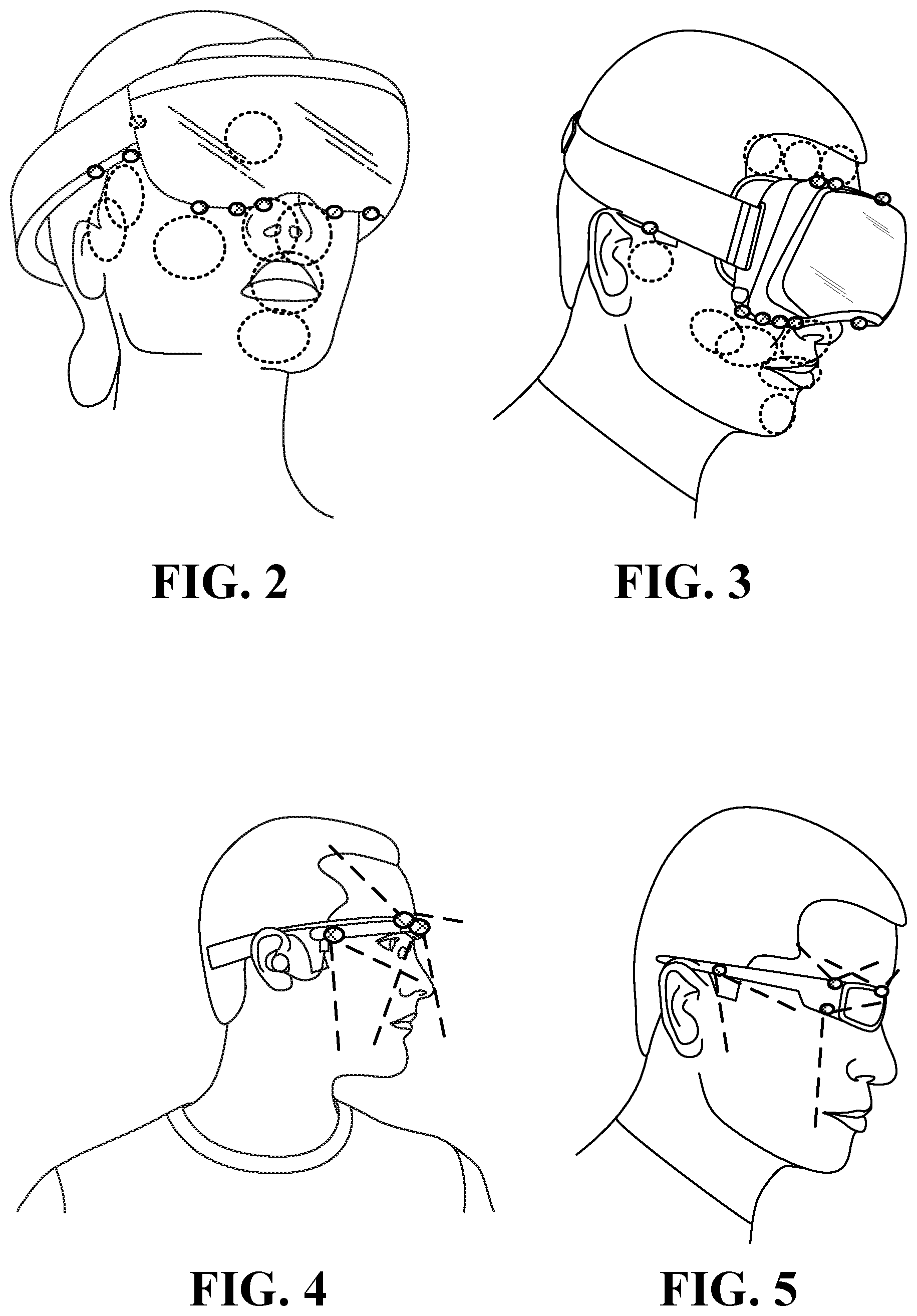
FIG. 2 illustrates inward-facing head-mounted cameras coupled to an augmented reality device;
FIG. 3 illustrates head-mounted cameras coupled to a virtual reality device;
FIG. 4 illustrates a side view of head-mounted cameras coupled to an augmented reality device;
FIG. 5 illustrates a side view of head-mounted cameras coupled to a sunglasses frame;
FIG. 6 to FIG. 9 illustrate HMSs configured to measure various ROIs relevant to some of the embodiments describes herein;
FIG. 10 to FIG. 13 illustrate various embodiments of systems that include inward-facing head-mounted cameras having multi-pixel sensors (FPA sensors);
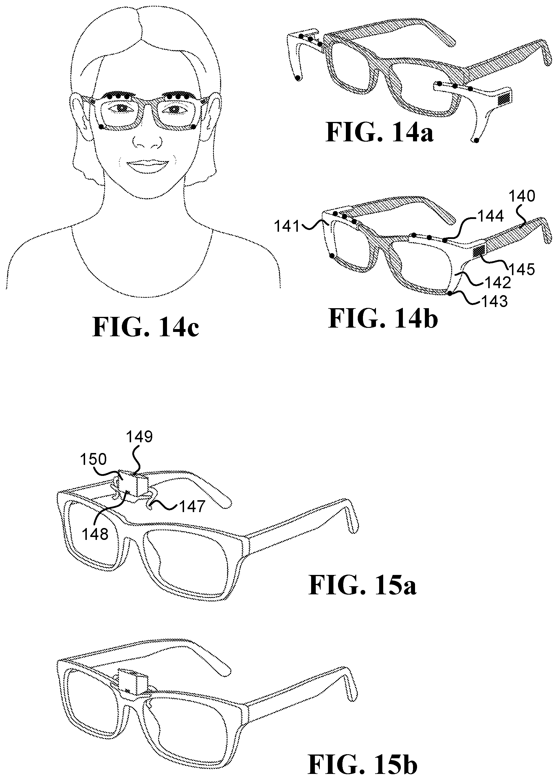
FIG. 14a, FIG. 14b, and FIG. 14c illustrate embodiments of two right and left clip-on devices that re configured to attached/detached from an eyeglasses frame;
FIG. 15a and FIG. 15b illustrate an embodiment of a clip-on device that includes inward-facing head-mounted cameras pointed at the lower part of the face and the forehead;
FIG. 16a and FIG. 16b illustrate embodiments of right and left clip-on devices that are configured to be attached behind an eyeglasses frame;
FIG. 17a and FIG. 17b illustrate an embodiment of a single-unit clip-on device that is configured to be attached behind an eyeglasses frame;
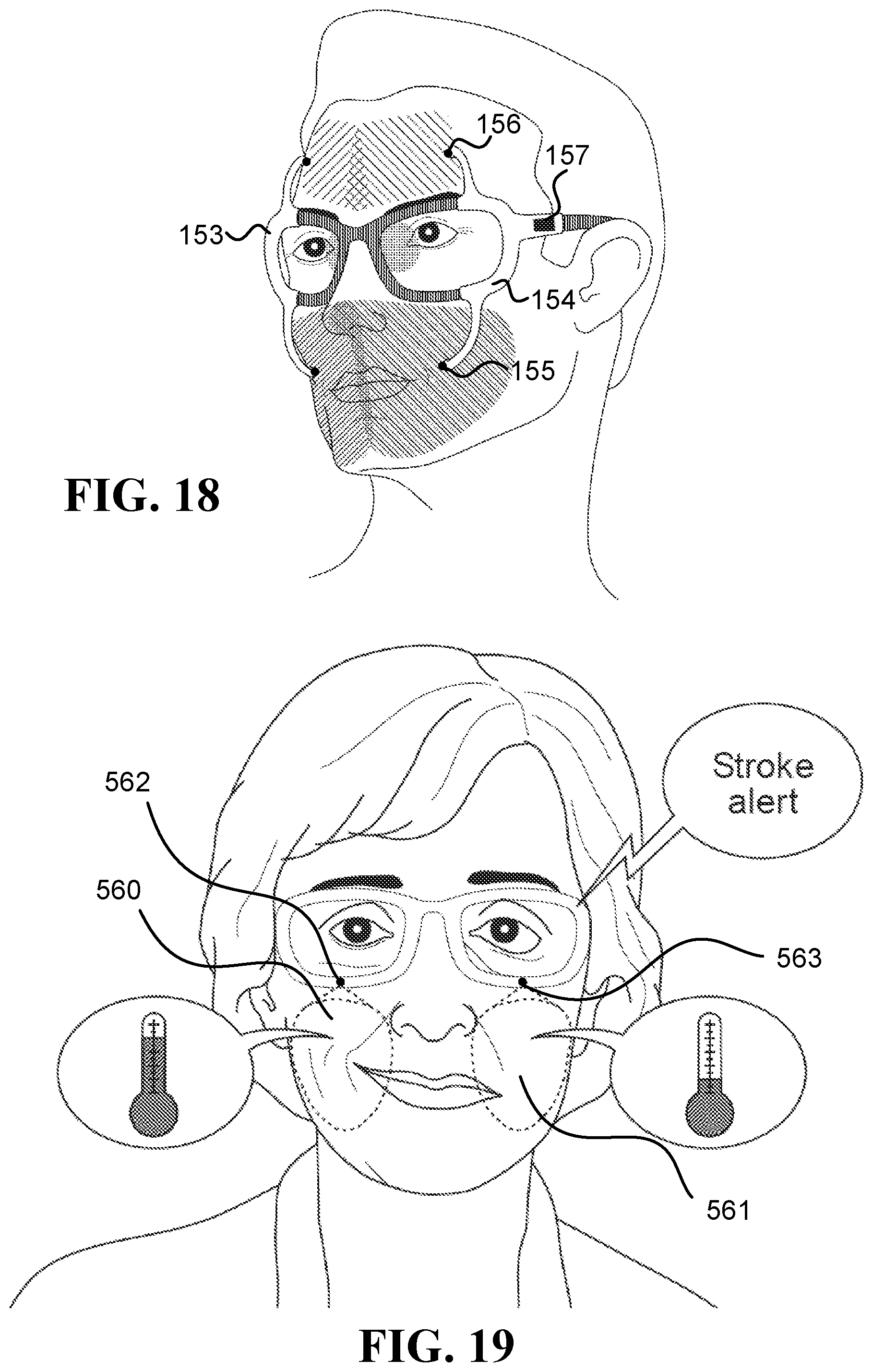
FIG. 18 illustrates embodiments of right and left clip-on devices, which are configured to be attached/detached from an eyeglasses frame, and have protruding arms to hold inward-facing head-mounted cameras;
FIG. 19 illustrates a scenario in which an alert regarding a possible stroke is issued;
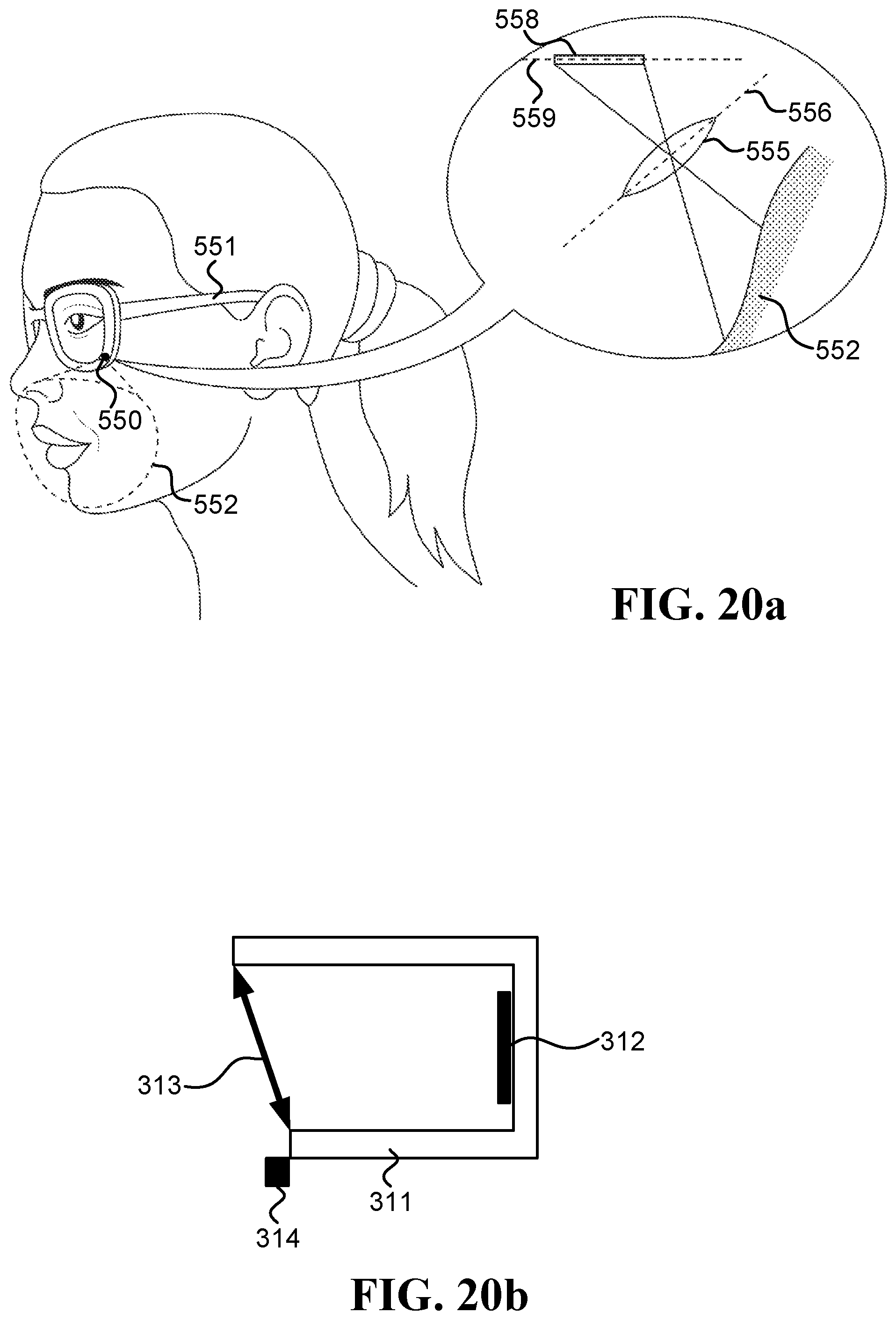
FIG. 20a is a schematic illustration of an inward-facing head-mounted camera embedded in an eyeglasses frame, which utilizes the Scheimpflug principle;
FIG. 20b is a schematic illustration of a camera that is able to change the relative tilt between its lens and sensor planes according to the Scheimpflug principle;
FIG. 21a and FIG. 21b illustrate a scenario in which a user is alerted about an expected allergic reaction;
FIG. 22 illustrates a scenario in which a trigger of an allergic reaction may be identified;
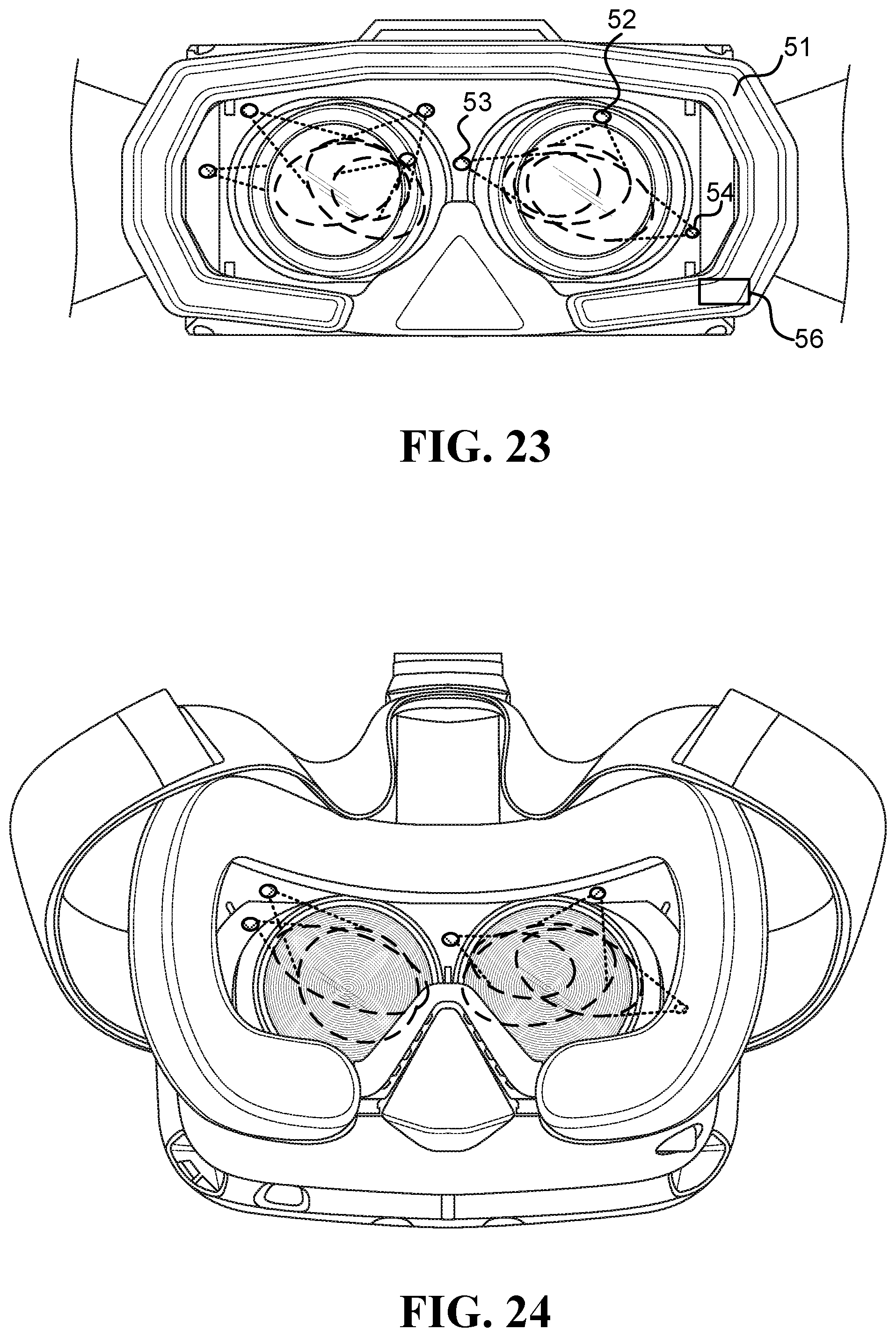
FIG. 23 illustrates an embodiment of an HMS able to measure stress level;
FIG. 24 illustrates examples of asymmetric locations of inward-facing head-mounted thermal cameras (CAMs) that measure the periorbital areas;
FIG. 25 illustrates an example of symmetric locations of the CAMs that measure the periorbital areas;
FIG. 26 illustrates a scenario in which a system suggests to the user to take a break in order to reduce the stress level;
FIG. 27a illustrates a child watching a movie while wearing an eyeglasses frame with at least five CAMs;
FIG. 27b illustrates generation of a graph of the stress level of the child detected at different times while different movie scenes were viewed;
FIG. 28 illustrates an embodiment of a system that generates a personalized model for detecting stress based on thermal measurements of the face;
FIG. 29 illustrates an embodiment of a system that includes a user interface, which notifies a user when the stress level of the user reaches a predetermined threshold;
FIG. 30 illustrates an embodiment of a system that selects a stressor; and
FIG. 31a and FIG. 31b are schematic illustrations of embodiments of computers.
DETAILED DESCRIPTION
A "thermal camera" refers herein to a non-contact device that measures electromagnetic radiation having wavelengths longer than 2500 nanometer (nm) and does not touch its region of interest (ROI). A thermal camera may include one sensing element (pixel), or multiple sensing elements that are also referred to herein as "sensing pixels", "pixels", and/or focal-plane array (FPA). A thermal camera may be based on an uncooled thermal sensor, such as a thermopile sensor, a microbolometer sensor (where microbolometer refers to any type of a bolometer sensor and its equivalents), a pyroelectric sensor, or a ferroelectric sensor.
Sentences in the form of "thermal measurements of an ROI" (usually denoted TH.sub.ROI or some variant thereof) refer to at least one of: (i) temperature measurements of the ROI (T.sub.ROI), such as when using thermopile or microbolometer sensors, and (ii) temperature change measurements of the ROI (.DELTA.T.sub.ROI), such as when using a pyroelectric sensor or when deriving the temperature changes from temperature measurements taken at different times by a thermopile sensor or a microbolometer sensor.
In some embodiments, a device, such as a thermal camera, may be positioned such that it occludes an ROI on the user's face, while in other embodiments, the device may be positioned such that it does not occlude the ROI. Sentences in the form of "the system/camera does not occlude the ROI" indicate that the ROI can be observed by a third person located in front of the user and looking at the ROI, such as illustrated by all the ROIs in FIG. 7, FIG. 11 and FIG. 19. Sentences in the form of "the system/camera occludes the ROI" indicate that some of the ROIs cannot be observed directly by that third person, such as ROIs 19 and 37 that are occluded by the lenses in FIG. 1a, and ROIs 97 and 102 that are occluded by cameras 91 and 96, respectively, in FIG. 9.
Although many of the disclosed embodiments can use occluding thermal cameras successfully, in certain scenarios, such as when using an HMS on a daily basis and/or in a normal day-to-day setting, using thermal cameras that do not occlude their ROIs on the face may provide one or more advantages to the user, to the HMS, and/or to the thermal cameras, which may relate to one or more of the following: esthetics, better ventilation of the face, reduced weight, simplicity to wear, and reduced likelihood to being tarnished.
A "Visible-light camera" refers to a non-contact device designed to detect at least some of the visible spectrum, such as cameras with optical lenses and CMOS or CCD sensors.
The term "inward-facing head-mounted camera" refers to a camera configured to be worn on a user's head and to remain pointed at its ROI, which is on the user's face, also when the user's head makes angular and lateral movements (such as movements with an angular velocity above 0.1 rad/sec, above 0.5 rad/sec, and/or above 1 rad/sec). A head-mounted camera (which may be inward-facing and/or outward-facing) may be physically coupled to a frame worn on the user's head, may be attached to eyeglass using a clip-on mechanism (configured to be attached to and detached from the eyeglasses), or may be mounted to the user's head using any other known device that keeps the camera in a fixed position relative to the user's head also when the head moves. Sentences in the form of "camera physically coupled to the frame" mean that the camera moves with the frame, such as when the camera is fixed to (or integrated into) the frame, or when the camera is fixed to (or integrated into) an element that is physically coupled to the frame. The abbreviation "CAM" denotes "inward-facing head-mounted thermal camera", the abbreviation "CAM.sub.out" denotes "outward-facing head-mounted thermal camera", the abbreviation "VCAM" denotes "inward-facing head-mounted visible-light camera", and the abbreviation "VCAM.sub.out" denotes "outward-facing head-mounted visible-light camera".
Sentences in the form of "a frame configured to be worn on a user's head" or "a frame worn on a user's head" refer to a mechanical structure that loads more than 50% of its weight on the user's head. For example, an eyeglasses frame may include two temples connected to two rims connected by a bridge; the frame in Oculus Rift.TM. includes the foam placed on the user's face and the straps; and the frames in Google Glass.TM. and Spectacles by Snap Inc. are similar to eyeglasses frames. Additionally or alternatively, the frame may connect to, be affixed within, and/or be integrated with, a helmet (e.g., sports, motorcycle, bicycle, and/or combat helmets) and/or a brainwave-measuring headset.
When a thermal camera is inward-facing and head-mounted, challenges faced by systems known in the art that are used to acquire thermal measurements, which include non-head-mounted thermal cameras, may be simplified and even eliminated with some of the embodiments described herein. Some of these challenges may involve dealing with complications caused by movements of the user, image registration, ROI alignment, tracking based on hot spots or markers, and motion compensation in the IR domain.
In various embodiments, cameras are located close to a user's face, such as at most 2 cm, 5 cm, 10 cm, 15 cm, or 20 cm from the face (herein "cm" denotes to centimeters). The distance from the face/head in sentences such as "a camera located less than 15 cm from the face/head" refers to the shortest possible distance between the camera and the face/head. The head-mounted cameras used in various embodiments may be lightweight, such that each camera weighs below 10 g, 5 g, 1 g, and/or 0.5 g (herein "g" denotes to grams).
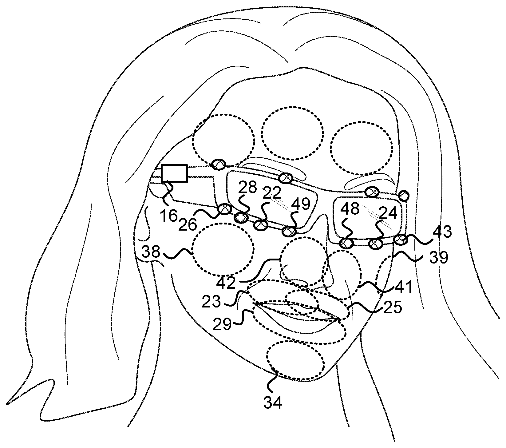
The following figures show various examples of HMSs equipped with head-mounted cameras. FIG. 1a illustrates various inward-facing head-mounted cameras coupled to an eyeglasses frame 15. Cameras 10 and 12 measure regions 11 and 13 on the forehead, respectively. Cameras 18 and 36 measure regions on the periorbital areas 19 and 37, respectively. The HMS further includes an optional computer 16, which may include a processor, memory, a battery and/or a communication module. FIG. 1b illustrates a similar HMS in which inward-facing head-mounted cameras 48 and 49 measure regions 41 and 41, respectively. Cameras 22 and 24 measure regions 23 and 25, respectively. Camera 28 measures region 29. And cameras 26 and 43 measure regions 38 and 39, respectively.
FIG. 2 illustrates inward-facing head-mounted cameras coupled to an augmented reality device such as Microsoft HoloLens.TM.. FIG. 3 illustrates head-mounted cameras coupled to a virtual reality device such as Facebook's Oculus Rift.TM.. FIG. 4 is a side view illustration of head-mounted cameras coupled to an augmented reality device such as Google Glass.TM.. FIG. 5 is another side view illustration of head-mounted cameras coupled to a sunglasses frame.
FIG. 6 to FIG. 9 illustrate HMSs configured to measure various ROIs relevant to some of the embodiments describes herein. FIG. 6 illustrates a frame 35 that mounts inward-facing head-mounted cameras 30 and 31 that measure regions 32 and 33 on the forehead, respectively. FIG. 7 illustrates a frame 75 that mounts inward-facing head-mounted cameras 70 and 71 that measure regions 72 and 73 on the forehead, respectively, and inward-facing head-mounted cameras 76 and 77 that measure regions 78 and 79 on the upper lip, respectively. FIG. 8 illustrates a frame 84 that mounts inward-facing head-mounted cameras 80 and 81 that measure regions 82 and 83 on the sides of the nose, respectively. And FIG. 9 illustrates a frame 90 that includes (i) inward-facing head-mounted cameras 91 and 92 that are mounted to protruding arms and measure regions 97 and 98 on the forehead, respectively, (ii) inward-facing head-mounted cameras 95 and 96, which are also mounted to protruding arms, which measure regions 101 and 102 on the lower part of the face, respectively, and (iii) head-mounted cameras 93 and 94 that measure regions on the periorbital areas 99 and 100, respectively.
FIG. 10 to FIG. 13 illustrate various inward-facing head-mounted cameras having multi-pixel sensors (FPA sensors), configured to measure various ROIs relevant to some of the embodiments describes herein. FIG. 10 illustrates head-mounted cameras 120 and 122 that measure regions 121 and 123 on the forehead, respectively, and mounts head-mounted camera 124 that measure region 125 on the nose. FIG. 11 illustrates head-mounted cameras 126 and 128 that measure regions 127 and 129 on the upper lip, respectively, in addition to the head-mounted cameras already described in FIG. 10. FIG. 12 illustrates head-mounted cameras 130 and 132 that measure larger regions 131 and 133 on the upper lip and the sides of the nose, respectively. And FIG. 13 illustrates head-mounted cameras 134 and 137 that measure regions 135 and 138 on the right and left cheeks and right and left sides of the mouth, respectively, in addition to the head-mounted cameras already described in FIG. 12.
In some embodiments, the head-mounted cameras may be physically coupled to the frame using a clip-on device configured to be attached/detached from a pair of eyeglasses in order to secure/release the device to/from the eyeglasses, multiple times. The clip-on device holds at least an inward-facing camera, a processor, a battery, and a wireless communication module. Most of the clip-on device may be located in front of the frame (as illustrated in FIG. 14b. FIG. 15b, and FIG. 18), or alternatively, most of the clip-on device may be located behind the frame, as illustrated in FIG. 16b and FIG. 17b.
FIG. 14a FIG. 14b, and FIG. 14c illustrate two right and left clip-on devices 141 and 142, respectively, configured to attached/detached from an eyeglasses frame 140. The clip-on device 142 includes an inward-facing head-mounted camera 143 pointed at a region on the lower part of the face (such as the upper lip, mouth, nose, and/or cheek), an inward-facing head-mounted camera 144 pointed at the forehead, and other electronics 145 (such as a processor, a battery, and/or a wireless communication module). The clip-on devices 141 and 142 may include additional cameras illustrated in the drawings as black circles.
FIG. 15a and FIG. 15b illustrate a clip-on device 147 that includes an inward-facing head-mounted camera 148 pointed at a region on the lower part of the face (such as the nose), and an inward-facing head-mounted camera 149 pointed at the forehead. The other electronics (such as a processor, a battery, and/or a wireless communication module) is located inside the box 150, which also holds the cameras 148 and 149.
FIG. 16a and FIG. 16b illustrate two right and left clip-on devices 160 and 161, respectively, configured to be attached behind an eyeglasses frame 165. The clip-on device 160 includes an inward-facing head-mounted camera 162 pointed at a region on the lower part of the face (such as the upper lip, mouth, nose, and/or cheek), an inward-facing head-mounted camera 163 pointed at the forehead, and other electronics 164 (such as a processor, a battery, and/or a wireless communication module). The clip-on devices 160 and 161 may include additional cameras illustrated in the drawings as black circles.
FIG. 17a and FIG. 17b illustrate a single-unit clip-on device 170, configured to be attached behind an eyeglasses frame 176. The single-unit clip-on device 170 includes inward-facing head-mounted cameras 171 and 172 pointed at regions on the lower part of the face (such as the upper lip, mouth, nose, and/or cheek), inward-facing head-mounted cameras 173 and 174 pointed at the forehead, a spring 175 configured to apply force that holds the clip-on device 170 to the frame 176, and other electronics 177 (such as a processor, a battery, and/or a wireless communication module). The clip-on device 170 may include additional cameras illustrated in the drawings as black circles.
FIG. 18 illustrates two right and left clip-on devices 153 and 154, respectively, configured to attached/detached from an eyeglasses frame, and having protruding arms to hold the inward-facing head-mounted cameras. Head-mounted camera 155 measures a region on the lower part of the face, head-mounted camera 156 measures regions on the forehead, and the left clip-on device 154 further includes other electronics 157 (such as a processor, a battery, and/or a wireless communication module). The clip-on devices 153 and 154 may include additional cameras illustrated in the drawings as black circles.
It is noted that the elliptic and other shapes of the ROIs in some of the drawings are just for illustration purposes, and the actual shapes of the ROIs are usually not as illustrated. It is possible to calculate the accurate shape of an ROI using various methods, such as a computerized simulation using a 3D model of the face and a model of a head-mounted system (HMS) to which a thermal camera is physically coupled, or by placing a LED instead of the sensor (while maintaining the same field of view) and observing the illumination pattern on the face. Furthermore, illustrations and discussions of a camera represent one or more cameras, where each camera may have the same FOV and/or different FOVs. Unless indicated to the contrary, the cameras may include one or more sensing elements (pixels), even when multiple sensing elements do not explicitly appear in the figures; when a camera includes multiple sensing elements then the illustrated ROI usually refers to the total ROI captured by the camera, which is made of multiple regions that are respectively captured by the different sensing elements. The positions of the cameras in the figures are just for illustration, and the cameras may be placed at other positions on the HMS.
Sentences in the form of an "ROI on an area", such as ROI on the forehead or an ROI on the nose, refer to at least a portion of the area. Depending on the context, and especially when using a CAM having just one pixel or a small number of pixels, the ROI may cover another area (in addition to the area). For example, a sentence in the form of "an ROI on the nose" may refer to either: 100% of the ROI is on the nose, or some of the ROI is on the nose and some of the ROI is on the upper lip.
Various embodiments described herein involve detections of physiological responses based on user measurements. Some examples of physiological responses include stress, an allergic reaction, an asthma attack, a stroke, dehydration, intoxication, or a headache (which includes a migraine). Other examples of physiological responses include manifestations of fear, startle, sexual arousal, anxiety, joy, pain or guilt. Still other examples of physiological responses include physiological signals such as a heart rate or a value of a respiratory parameter of the user. Optionally, detecting a physiological response may involve one or more of the following: determining whether the user has/had the physiological response, identifying an imminent attack associated with the physiological response, and/or calculating the extent of the physiological response.
In some embodiments, detection of the physiological response is done by processing thermal measurements that fall within a certain window of time that characterizes the physiological response. For example, depending on the physiological response, the window may be five seconds long, thirty seconds long, two minutes long, five minutes long, fifteen minutes long, or one hour long. Detecting the physiological response may involve analysis of thermal measurements taken during multiple of the above-described windows, such as measurements taken during different days. In some embodiments, a computer may receive a stream of thermal measurements, taken while the user wears an HMS with coupled thermal cameras during the day, and periodically evaluate measurements that fall within a sliding window of a certain size.
In some embodiments, models are generated based on measurements taken over long periods. Sentences of the form of "measurements taken during different days" or "measurements taken over more than a week" are not limited to continuous measurements spanning the different days or over the week, respectively. For example, "measurements taken over more than a week" may be taken by eyeglasses equipped with thermal cameras, which are worn for more than a week, 8 hours a day. In this example, the user is not required to wear the eyeglasses while sleeping in order to take measurements over more than a week. Similarly, sentences of the form of "measurements taken over more than 5 days, at least 2 hours a day" refer to a set comprising at least 10 measurements taken over 5 different days, where at least two measurements are taken each day at times separated by at least two hours.
Utilizing measurements taken of a long period (e.g., measurements taken on "different days") may have an advantage, in some embodiments, of contributing to the generalizability of a trained model. Measurements taken over the long period likely include measurements taken in different environments and/or measurements taken while the measured user was in various physiological and/or mental states (e.g., before/after meals and/or while the measured user was sleepy/energetic/happy/depressed, etc.). Training a model on such data can improve the performance of systems that utilize the model in the diverse settings often encountered in real-world use (as opposed to controlled laboratory-like settings). Additionally, taking the measurements over the long period may have the advantage of enabling collection of a large amount of training data that is required for some machine learning approaches (e.g., "deep learning").
Detecting the physiological response may involve performing various types of calculations by a computer. Optionally, detecting the physiological response may involve performing one or more of the following operations: comparing thermal measurements to a threshold (when the threshold is reached that may be indicative of an occurrence of the physiological response), comparing thermal measurements to a reference time series, and/or by performing calculations that involve a model trained using machine learning methods. Optionally, the thermal measurements upon which the one or more operations are performed are taken during a window of time of a certain length, which may optionally depend on the type of physiological response being detected. In one example, the window may be shorter than one or more of the following durations: five seconds, fifteen seconds, one minute, five minutes, thirty minute, one hour, four hours, one day, or one week. In another example, the window may be longer than one or more of the aforementioned durations. Thus, when measurements are taken over a long period, such as measurements taken over a period of more than a week, detection of the physiological response at a certain time may be done based on a subset of the measurements that falls within a certain window near the certain time; the detection at the certain time does not necessarily involve utilizing all values collected throughout the long period.
In some embodiments, detecting the physiological response of a user may involve utilizing baseline thermal measurement values, most of which were taken when the user was not experiencing the physiological response. Optionally, detecting the physiological response may rely on observing a change to typical temperatures at one or more ROIs (the baseline), where different users might have different typical temperatures at the ROIs (i.e., different baselines). Optionally, detecting the physiological response may rely on observing a change to a baseline level, which is determined based on previous measurements taken during the preceding minutes and/or hours.
In some embodiments, detecting a physiological response involves determining the extent of the physiological response, which may be expressed in various ways that are indicative of the extent of the physiological response, such as: (i) a binary value indicative of whether the user experienced, and/or is experiencing, the physiological response, (ii) a numerical value indicative of the magnitude of the physiological response, (iii) a categorial value indicative of the severity/extent of the physiological response, (iv) an expected change in thermal measurements of an ROI (denoted TH.sub.ROI or some variation thereof), and/or (v) rate of change in TH.sub.ROI. Optionally, when the physiological response corresponds to a physiological signal (e.g., a heart rate, a breathing rate, and an extent of frontal lobe brain activity), the extent of the physiological response may be interpreted as the value of the physiological signal.
Herein, "machine learning" methods refers to learning from examples using one or more approaches. Optionally, the approaches may be considered supervised, semi-supervised, and/or unsupervised methods. Examples of machine learning approaches include: decision tree learning, association rule learning, regression models, nearest neighbors classifiers, artificial neural networks, deep learning, inductive logic programming, support vector machines, clustering, Bayesian networks, reinforcement learning, representation learning, similarity and metric learning, sparse dictionary learning, genetic algorithms, rule-based machine learning, and/or learning classifier systems.
Herein, a "machine learning-based model" is a model trained using machine learning methods. For brevity's sake, at times, a "machine learning-based model" may simply be called a "model". Referring to a model as being "machine learning-based" is intended to indicate that the model is trained using machine learning methods (otherwise, "model" may also refer to a model generated by methods other than machine learning).
In some embodiments, which involve utilizing a machine learning-based model, a computer is configured to detect the physiological response by generating feature values based on the thermal measurements (and possibly other values), and/or based on values derived therefrom (e.g., statistics of the measurements). The computer then utilizes the machine learning-based model to calculate, based on the feature values, a value that is indicative of whether, and/or to what extent, the user is experiencing (and/or is about to experience) the physiological response. Optionally, calculating said value is considered "detecting the physiological response". Optionally, the value calculated by the computer is indicative of the probability that the user has/had the physiological response.
Herein, feature values may be considered input to a computer that utilizes a model to perform the calculation of a value, such as the value indicative of the extent of the physiological response mentioned above. It is to be noted that the terms "feature" and "feature value" may be used interchangeably when the context of their use is clear. However, a "feature" typically refers to a certain type of value, and represents a property, while "feature value" is the value of the property with a certain instance (sample). For example, a feature may be temperature at a certain ROI, while the feature value corresponding to that feature may be 36.9.degree. C. in one instance and 37.3.degree. C. in another instance.
In some embodiments, a machine learning-based model used to detect a physiological response is trained based on data that includes samples. Each sample includes feature values and a label. The feature values may include various types of values. At least some of the feature values of a sample are generated based on measurements of a user taken during a certain period of time (e.g., thermal measurements taken during the certain period of time). Optionally, some of the feature values may be based on various other sources of information described herein. The label is indicative of a physiological response of the user corresponding to the certain period of time. Optionally, the label may be indicative of whether the physiological response occurred during the certain period and/or the extent of the physiological response during the certain period. Additionally or alternatively, the label may be indicative of how long the physiological response lasted. Labels of samples may be generated using various approaches, such as self-report by users, annotation by experts that analyze the training data, automatic annotation by a computer that analyzes the training data and/or analyzes additional data related to the training data, and/or utilizing additional sensors that provide data useful for generating the labels. It is to be noted that herein when it is stated that a model is trained based on certain measurements (e.g., "a model trained based on TH.sub.ROI taken on different days"), it means that the model was trained on samples comprising feature values generated based on the certain measurements and labels corresponding to the certain measurements. Optionally, a label corresponding to a measurement is indicative of the physiological response at the time the measurement was taken.
Various types of feature values may be generated based on thermal measurements. In one example, some feature values are indicative of temperatures at certain ROIs. In another example, other feature values may represent a temperature change at certain ROIs. The temperature changes may be with respect to a certain time and/or with respect to a different ROI. In order to better detect physiological responses that take some time to manifest, in some embodiments, some feature values may describe temperatures (or temperature changes) at a certain ROI at different points of time. Optionally, these feature values may include various functions and/or statistics of the thermal measurements such as minimum/maximum measurement values and/or average values during certain windows of time.
It is to be noted that when it is stated that feature values are generated based on data comprising multiple sources, it means that for each source, there is at least one feature value that is generated based on that source (and possibly other data). For example, stating that feature values are generated from thermal measurements of first and second ROIs (TH.sub.ROI1 and TH.sub.ROI2, respectively) means that the feature values may include a first feature value generated based on TH.sub.ROI1 and a second feature value generated based on TH.sub.ROI2. Optionally, a sample is considered generated based on measurements of a user (e.g., measurements comprising TH.sub.ROI1 and TH.sub.ROI2) when it includes feature values generated based on the measurements of the user.
In addition to feature values that are generated based on thermal measurements, in some embodiments, at least some feature values utilized by a computer (e.g., to detect a physiological response or train a mode) may be generated based on additional sources of data that may affect temperatures measured at various facial ROIs. Some examples of the additional sources include: (i) measurements of the environment such as temperature, humidity level, noise level, elevation, air quality, a wind speed, precipitation, and infrared radiation; (ii) contextual information such as the time of day (e.g., to account for effects of the circadian rhythm), day of month (e.g., to account for effects of the lunar rhythm), day in the year (e.g., to account for seasonal effects), and/or stage in a menstrual cycle; (iii) information about the user being measured such as sex, age, weight, height, and/or body build. Alternatively or additionally, at least some feature values may be generated based on physiological signals of the user obtained by sensors that are not thermal cameras, such as a visible-light camera, a photoplethysmogram (PPG) sensor, an electrocardiogram (ECG) sensor, an electroencephalography (EEG) sensor, a galvanic skin response (GSR) sensor, or a thermistor.
The machine learning-based model used to detect a physiological response may be trained, in some embodiments, based on data collected in day-to-day, real world scenarios. As such, the data may be collected at different times of the day, while users perform various activities, and in various environmental conditions. Utilizing such diverse training data may enable a trained model to be more resilient to the various effects different conditions can have on the values of thermal measurements, and consequently, be able to achieve better detection of the physiological response in real world day-to-day scenarios.
Since real world day-to-day conditions are not the same all the time, sometimes detection of the physiological response may be hampered by what is referred to herein as "confounding factors". A confounding factor can be a cause of warming and/or cooling of certain regions of the face, which is unrelated to a physiological response being detected, and as such, may reduce the accuracy of the detection of the physiological response. Some examples of confounding factors include: (i) environmental phenomena such as direct sunlight, air conditioning, and/or wind; (ii) things that are on the user's face, which are not typically there and/or do not characterize the faces of most users (e.g., cosmetics, ointments, sweat, hair, facial hair, skin blemishes, acne, inflammation, piercings, body paint, and food leftovers); (iii) physical activity that may affect the user's heart rate, blood circulation, and/or blood distribution (e.g., walking, running, jumping, and/or bending over); (iv) consumption of substances to which the body has a physiological response that may involve changes to temperatures at various facial ROIs, such as various medications, alcohol, caffeine, tobacco, and/or certain types of food; and/or (v) disruptive facial movements (e.g., frowning, talking, eating, drinking, sneezing, and coughing).
Occurrences of confounding factors may not always be easily identified in thermal measurements. Thus, in some embodiments, systems may incorporate measures designed to accommodate for the confounding factors. In some embodiments, these measures may involve generating feature values that are based on additional sensors, other than the thermal cameras. In some embodiments, these measures may involve refraining from detecting the physiological response, which should be interpreted as refraining from providing an indication that the user has the physiological response. For example, if an occurrence of a certain confounding factor is identified, such as strong directional sunlight that heats one side of the face, the system may refrain from detecting that the user had a stroke. In this example, the user may not be alerted even though a temperature difference between symmetric ROIs on both sides of the face reaches a threshold that, under other circumstances, would warrant alerting the user.
Training data used to train a model for detecting a physiological response may include, in some embodiments, a diverse set of samples corresponding to various conditions, some of which involve occurrence of confounding factors (when there is no physiological response and/or when there is a physiological response). Having samples in which a confounding factor occurs (e.g., the user is in direct sunlight or touches the face) can lead to a model that is less susceptible to wrongfully detect the physiological response (which may be considered an occurrence of a false positive) in real world situations.
After a model is trained, the model may be provided for use by a system that detects the physiological response. Providing the model may involve performing different operations, such as forwarding the model to the system via a computer network and/or a shared computer storage medium, storing the model in a location from which the system can retrieve the model (such as a database and/or cloud-based storage), and/or notifying the system regarding the existence of the model and/or regarding an update to the model.
A model for detecting a physiological response may include different types of parameters. Following are some examples of various possibilities for the model and the type of calculations that may be accordingly performed by a computer in order to detect the physiological response: (a) the model comprises parameters of a decision tree. Optionally, the computer simulates a traversal along a path in the decision tree, determining which branches to take based on the feature values. A value indicative of the physiological response may be obtained at the leaf node and/or based on calculations involving values on nodes and/or edges along the path: (b) the model comprises parameters of a regression model (e.g., regression coefficients in a linear regression model or a logistic regression model). Optionally, the computer multiplies the feature values (which may be considered a regressor) with the parameters of the regression model in order to obtain the value indicative of the physiological response; and/or (c) the model comprises parameters of a neural network. For example, the parameters may include values defining at least the following: (i) an interconnection pattern between different layers of neurons, (ii) weights of the interconnections, and (iii) activation functions that convert each neuron's weighted input to its output activation. Optionally, the computer provides the feature values as inputs to the neural network, computes the values of the various activation functions and propagates values between layers, and obtains an output from the network, which is the value indicative of the physiological response.
A user interface (UI) may be utilized, in some embodiments, to notify the user and/or some other entity, such as a caregiver, about the physiological response and/or present an alert responsive to an indication that the extent of the physiological response reaches a threshold. The UI may include a screen to display the notification and/or alert, a speaker to play an audio notification, a tactile UI, and/or a vibrating UI. In some embodiments, "alerting" about a physiological response of a user refers to informing about one or more of the following: the occurrence of a physiological response that the user does not usually have (e.g., a stroke, intoxication, and/or dehydration), an imminent physiological response (e.g., an allergic reaction, an epilepsy attack, and/or a migraine), and an extent of the physiological response reaching a threshold (e.g., stress and/or anger reaching a predetermined level).
Many physiological responses are manifested in the temperature that is measured on various regions of the human face. For example, temperatures of the nose may be indicative of whether the person is having an allergic reaction. Even though monitoring and analyzing facial temperatures can be useful for many health-related and life logging-related applications, collecting such data over time, when people are going about their daily activities, can be very difficult. Typically, collection of such data involves utilizing thermal cameras that are bulky, expensive, and need to be continually pointed at a person's face. Additionally, due to the movements involved in day-to-day activities, various image analysis procedures need to be performed, such as face tracking and image registration, in order to collect the required measurements. Therefore, there is a need for way to be able to collect measurements temperatures of the nose, and possibly other regions of the face, and to utilize them for various applications such as detecting an allergic reaction. Preferably, the measurements need to be able to be collected over a long period, while the person performs various day-to-day activities.
One application for which thermal measurements of the face may be useful is to detect an allergic reaction. In one embodiment, a system configured to detect an allergic reaction of a user includes at least a CAM that takes thermal measurements of a region on the nose (TH.sub.N) of the user, and a computer that detects an allergic reaction of the user based on TH.sub.N. Optionally, an allergen may be any substance that causes the user to experience an allergic reaction due to the exposure of the user to the allergen (e.g., by consuming, inhaling, and/or coming into physical contact with the allergen). For example, an allergic reaction may be a reaction to a drug, peanuts, eggs, wheat, dairy products, seafood, pollen, dust, and/or perfume.
In one embodiment, CAM is physically coupled to a frame worn on the user's head (e.g., a frame of glasses or an augmented reality display). Optionally, CAM is located less than 15 cm from the user's face. Optionally, CAM weighs less than 10 g, 5 g or 1 g. Optionally, CAM uses a thermopile, a pyroelectric sensor, or a microbolometer sensor, which may be a focal-plane array sensor. For example, CAM may be the thermal cameras 48 and/or 49, which are illustrated in FIG. 1b, or the thermal camera 540 illustrated in FIG. 22.
Optionally, multiple CAMs may be utilized to obtain measurements of various ROIs such as different regions/sides of the nose, mouth and/or cheeks. For example, allergic reaction may cause red eyes, itchy eyes, tearing eyes, swollen eyelids, and/or burning eyes/eyelids. In some cases, a thermal camera that captures a region on the periorbital (TH.sub.peri) around at least one of the eyes may detect an eye allergy symptom before the user is aware of the allergic reaction and/or used to assess the extent of the allergic reaction. As another example, allergic reaction may cause hives (urticaria) around the mouth and/or other parts of the face. In some cases, a thermal camera that captures the area around the mouth (TH.sub.lips) may detect the hives around the mouth before the user is aware of the allergic reaction and/or used to assess the extent of the allergic reaction. In still some cases, thermal measurements of regions on the right and/or left cheeks (TH.sub.ch) may help detecting the allergic reaction.
The computer is configured, in one embodiment, to detect the allergic reaction based on TH.sub.N and optionally other data, such as TH.sub.CH, TH.sub.peri, and/or TH.sub.lips mentioned above and/or other sources of information mentioned below. In one embodiment, detecting the allergic reaction may involve one or more of the following: determining whether the user is experiencing an allergic reaction, and/or determining the extent of the allergic reaction. Optionally, the extent of the allergic reaction may be indicative of the severity of the allergic reaction, and/or the duration of the allergic reaction (e.g., total time of the allergic reaction and/or the time remaining until the allergic reaction subsides).
In some cases, changes to temperatures at regions of the face (e.g., in the nasal area) occur quickly at the initial stages of an allergic reaction. Thus, the computer may detect the allergic reaction at its initial stages even before the user is aware of the allergic reaction. Thus, in some embodiments, detecting the allergic reaction involves detecting an onset of the allergic reaction, which may involve determining the time until the reaction reaches its peak severity (e.g., a rash, coughing, respiratory distress, sneezing) and/or determining the expected degree of severity (extent) of the allergic reaction.
In some cases, at the time the allergic reaction is identified, a user having the allergic reaction may not be aware of the allergic reaction. e.g., because the symptoms are not strong enough at the time. Thus, being notified about an allergic reaction before its full manifestation may have an advantage, in some embodiments, of allowing the user to take early action to alleviate and/or decrease the symptoms (e.g., take antihistamines) or seek medical attention.
In some allergic reactions, the nasal temperature can rise rapidly within minutes, before other more noticeable symptoms may manifest themselves (e.g., sneezing, itching, and/or respiratory problems). Thus, rising nasal temperatures may serve as an indication of an allergic reaction. For example, a fast increase due to an allergic reaction may correspond to an increase of more than 0.8.degree. C. within a period of less than 10 minutes, or even less than 5 minutes.
FIG. 21a and FIG. 21b illustrate a scenario in which a user is alerted about an expected allergic reaction. In FIG. 21a, the user's nasal temperature is normal. At that time, a cat, to which the user is allergic, walks past the user. FIG. 21b illustrates the situation shortly after. The user's nasal temperature has increased, and based on thermal measurements of the nasal region, a computer issues an alert to the user about the expected allergic reaction. Note that at the time the alert is issued, the user may not be aware of any symptoms of the allergic reaction. Receiving an early warning in this case may enable the user to take measures to alleviate the effects of the allergic reaction, such as taking an antihistamine medicine.
There are various ways the computer may utilize TH.sub.N and possibly other thermal measurements such as TH.sub.CH, TH.sub.peri, and/or TH.sub.lips, in order to detect the allergic reaction. In one embodiment, the computer may compare values derived from TH.sub.N (and/or from TH.sub.CH, TH.sub.peri, and/or TH.sub.lips) to a certain threshold, and determine whether the threshold is reached (which is indicative of an occurrence of the allergic reaction). Optionally, the threshold is determined based on previous thermal measurements of the user. Optionally, the threshold is determined based on previous thermal measurements of other users. In another embodiment, the computer may determine a similarity between a reference time series corresponding to the allergic reaction and TH.sub.N and optionally the other thermal measurements (or a time series derived therefrom). Optionally, when a sufficiently high similarity is detected, the computer may interpret that as an indication of an occurrence of the allergic reaction. The reference time series may be generated based on previous thermal measurements of the user and/or of other users.
In yet another embodiment, the computer may generate feature values based on thermal measurements comprising TH.sub.N and optionally TH.sub.CH, TH.sub.peri, and/or TH.sub.lips, and utilize a machine learning-based model to calculate, based on the feature values, a value indicative of whether the allergic reaction occurred and/or indicative of an extent of the allergic reaction (calculating the value be considered herein as "detecting the allergic reaction"). Optionally, the model was trained based on previous thermal measurements of the user. For example, the previous thermal measurements may include a first set of thermal measurements taken while the user had an allergic reaction, and a second set of thermal measurements taken while the user did not have an allergic reaction. In this example, the model may be considered a personalized model for the user. Additionally or alternatively, the model may be trained on thermal measurements of other users (e.g., a general model). Optionally, different models may be created to detect different types of allergic reactions, to detect allergic reactions to different allergens, and/or to detect different extents of an allergic reaction.
In one example, detection of the allergic reaction may involve the computer performing the following: (i) generating feature values based on thermal measurements comprising TH.sub.N and optionally TH.sub.CH, TH.sub.peri, and/or TH.sub.lips; and (ii) utilizing a model to detect the allergic reaction based on the feature values. Optionally, the model was trained based on previous thermal measurements of the user comprising TH.sub.N and optionally TH.sub.CH, TH.sub.peri, and/or TH.sub.lips, which were taken while the user had an allergic reaction. Alternatively, the model was trained based on a first set of previous thermal measurements of the user comprising TH.sub.N and optionally TH.sub.CH, TH.sub.peri, and/or TH.sub.lips, which were taken while the user had an allergic reaction, and a second set of previous thermal measurements of the user comprising TH.sub.N and optionally TH.sub.CH, TH.sub.peri, and/or TH.sub.lips, which were taken while the user did not have an allergic reaction.
In some embodiments, detecting the allergic reaction may involve utilizing baseline TH.sub.N, most of which were taken when the user did not have an allergic reaction. Thus, detecting the allergic reaction may rely on observing a change relative to typical temperatures at the ROIs. In one example, the computer detects the allergic reaction based a difference between TH.sub.N and a baseline value determined based on a set of previous TH.sub.N taken with CAM. In this example, most of TH.sub.N belonging to the set were taken while the user had an allergic reaction, or within thirty minutes before or after the user had an allergic reaction.
Confounding factors such as extensive physical activity, touching the nose, and/or direct sunlight aimed at the nose may lead, in some embodiments, to less accurate detections of an allergic reaction (e.g., by increasing the frequency of false detections of the allergic reaction). In some embodiments, the system may include a sensor that takes additional measurements (m.sub.conf) of the user, and/or of the environment in which the user was in while TH.sub.N were taken. Optionally, m.sub.conf are indicative of an extent to which a confounding factor occurred while TH.sub.N were taken. Another approach that may be utilized by the computer is to generate feature values based on m.sub.conf and to utilize these feature values in the detection of the allergic reaction.
Some of the embodiments described herein may be utilized to identify potential causes for the change (e.g., rise) of the temperature at an ROI. These causes may include inhaled allergens, food, drugs, and/or various chemicals which the user might have been exposed to (e.g., via ingestion, inhalation, and/or physical contact). In one embodiment, the computer may identify a potential allergen substance by estimating a time of exposure to the allergen from data indicative of a deviation over time of mean nasal temperature from a baseline and identifying the substances consumed by the user, and/or to which the user was exposed, around that time. For example, by identifying based on TH.sub.N when the nasal temperature started to rise, and taking into account the time required for the allergic reaction to be manifested via a temperature rise, a window of time can be determined during which the user was likely exposed to the allergen. Examining which substances the user was exposed to during the window can yield a list of one or more potential allergen substances. Optionally, the system alerts the user about the one or more potential allergen substances. Optionally, the system stores in a database potential allergen substances identified based on data indicative of a deviation over time of mean nasal temperature from baseline (such as allergens identified based on deviation over time of mean nasal temperature from baseline). In some embodiments, the system includes a camera that captures images of substances consumed by the user. Optionally, the camera is mounted to a frame worn on the user's head. Optionally, the system displays to the user an image of a substance associated with the potential allergen substance.
There are various known systems that may be utilized to monitor what substances a user was exposed to and/or what substances a user consumed. For example, systems that may be utilized to determine what the user ate or drank are described in the patent application US 20110318717 (Personalized Food Identification and Nutrition Guidance System), in the U.S. Pat. No. 9,053,483 (Personal audio/visual system providing allergy awareness), and in the U.S. Pat. No. 9,189,021 (Wearable food nutrition feedback system). Additionally, obtaining indications of possible allergens to which the user was exposed is described in the U.S. Pat. No. 9,000,933 (Automated allergy alerts). In one embodiment, upon identifying an increase in nasal temperature, the system can identify the potential cause to be one of the substances to which the user was exposed during a predetermined preceding duration, such as the preceding 20 min, 10 min, or 5 min.
FIG. 22 illustrates how the system may be utilized to identify a trigger of an allergic reaction. CAM 540 is coupled to a frame of eyeglasses worn by the user and takes thermal measurements of a region on the user's nose 541, while the user eats different types of food. The dotted lines on the graph indicate when the user started eating each type of food. The nasal temperature increases shortly after starting eating the persimmon; however, it may reach a threshold indicating an allergic reaction only after some time, during which the user eats the pizza or the ice cream. Thus, in this case, the allergic reaction should likely be attributed to the persimmon or the soup, and not attributed to the pizza or the ice cream. Optionally, outward-facing head-mounted visible-light camera 542 takes images of the food the user eats, and the computer uses image processing to detect the types of food.
Another approach for identifying a cause of an allergic reaction (a "trigger" of an allergic reaction), involves analysis of potential triggers and the user's detected response when affected by the potential triggers. In one embodiment, the computer is further configured to: receive indications of times during which the user was exposed to potential triggers of the allergic reaction, and select a trigger, from among the potential triggers, based on the indications and extents of the allergic reaction detected based on TH.sub.N. Optionally, during most of the time the user was affected by the trigger, an effect of the trigger, as manifested via changes to TH.sub.N, was higher than effects of most of the potential triggers. Optionally, a camera is utilized to take images of the surroundings of the user, and the computer generates at least some of the indications based on analysis of the images. In one example, the exposure to the potential triggers involves consuming a certain drug and/or a certain food item. In another example, the exposure to the potential triggers involves being exposed to pollen, dust, and/or a certain cosmetics product. In still another example, the exposure to the potential triggers involves the user being at a certain location, and/or the user being in contact with a certain animal.
Due to the mostly symmetric nature of the human body, when the face undergoes temperature changes, e.g., due to external factors such as the temperature in the environment or internal factors such as an activity-related rise in body temperature, the changes to the face are generally symmetric. That is, the temperature changes at a region of interest (ROI) on the left side of the face (e.g., the left side of the forehead) are similar to the temperature changes at the symmetric ROT on the right side of the face (e.g., the right side of the forehead). However, when the temperature on the face changes in an asymmetric way, this can be indicative of various physiological responses and/or undesirable phenomena. Some examples of phenomena that may be identified by detecting asymmetric thermal patterns ("thermal asymmetry") on a user's face include a headache, sinusitis, nerve damage, some types of strokes, orofacial pain, and Bell's palsy. Additionally, some forms of disorders such as Attention Deficit Hyperactivity Disorder (ADHD), stress, anxiety, and/or depression can also be identified based on thermal asymmetry of the forehead, and in some cases of other regions of the face.
In other cases, and sometime depending on personal characteristics of the user, certain physiological responses may manifest differently on different sides of the face. In particular, the temperatures at different positions on the right side of the face may not be a mirror image of the temperatures at the corresponding positions on the left side of the face. Thus, having two or more thermal cameras pointed at different areas of the face can, in some embodiments, help make more accurate detections of a physiological response. For example, stress may be manifested with some people by the cooling of an area on one side of the nose more than the symmetric area on the other side. Similarly, with some people, an allergic reaction may manifest by the nose heating to different extents on each of its sides. Thus, having, in this example, two or more thermal cameras pointed at different sides of the nose, may enable a more accurate detection of the physiological response.
Measuring and utilizing the asymmetric data also improves the robustness of the system against interferences that may cause an asymmetric thermal effect, such as an external heat source located to the user's side, a cooling air-conditioner that blows air from the top, touching and/or wiping one side of the face, and for some people also eating and/or conducting a physical activity. Therefore, utilizing thermal cameras pointed at symmetric ROIs may improve the system's ability to detect a physiological response compared to the case in which just one thermal camera is used.
In one embodiment, a system configured to collect thermal measurements indicative of thermal asymmetry on a user's face includes first and second inward-facing head-mounted thermal cameras (CAM1 and CAM2). Optionally, CAM1 and CAM2 are physically coupled to a frame worn on the user's head, and are located less than 15 cm, 5 cm, or 2 cm from the user's face. Optionally, CAM1 and CAM2 are located at least 0.5 cm to the right and to the left of the vertical symmetry axis that divides the face, respectively. Optionally, each of CAM1 and CAM2 weighs below 10 g, 5 g, or 1 g.
CAM1 and CAM2 take thermal measurements of regions on the right and left sides of the face (TH.sub.ROI1 and TH.sub.ROI2, respectively) of the user, and optionally do not occlude ROI.sub.1 and ROI.sub.2. Optionally, CAM1 and CAM2 are based on thermopile, microbolometer, or pyroelectric sensors, which may be focal-plane array sensors. Optionally, ROI.sub.1 and ROI.sub.2 have symmetric overlapping above 60%. In one example, CAM1 and CAM2 may be thermal cameras 120 and 122 in FIG. 10. In another example, CAM and CAM2 are thermal cameras 126 and 128 in FIG. 11.
The symmetric overlapping is considered with respect to the vertical symmetry axis that divides the face to the right and left portions. The symmetric overlapping between ROI.sub.1 and ROI.sub.2 may be observed by comparing the overlap between ROI.sub.1 and a mirror image of ROI.sub.2, where the mirror image is with respect to a mirror that is perpendicular to the front of the face and whose intersection with the face is along the vertical symmetry axis (which goes through the middle of the forehead and the middle of the nose). Depending on the application for which the thermal measurements are utilized, the ROIs may have different degrees of symmetric overlapping. In one example, the symmetric overlapping between ROI.sub.1 and ROI.sub.2 is above 80% of the smallest area from among the areas of ROI.sub.1 and ROI.sub.2. In another example, the overlap between ROI.sub.1 and ROI.sub.2 is above 25% and below 80% of the smallest area from among the areas of ROI.sub.1 and ROI.sub.2.
Depending on the locations of ROI.sub.1 and ROI.sub.2, in different embodiments, CAM1 and CAM2 may be located in specific locations on the frame and/or with respect to the face. In one example, ROI.sub.1 and ROI.sub.2 are on the nose and/or a region on the mouth, and CAM1 and CAM2 are located outside the exhale streams of the mouth and/or nostrils.
In one embodiment, each of CAM1 and CAM2 is located less than 10 cm from the face and there are angles greater than 20.degree. between the Frankfort horizontal plane and the optical axes of CAM1 and CAM2.
Due to the angle between the optical axis of CAM1 and CAM2 and the Frankfort horizontal plane, in some embodiments, the Scheimpflug principle, may be employed in order to capture sharper images. For example, when the user wears the frame, CAM1 and/or CAM2 may have a certain tilt greater than 2.degree. between their sensor and lens planes, in order to produce the sharper images.
In one embodiment, CAM1 and CAM2 utilize focal-plane array (FPA) sensors. Optionally, each FPA includes at least 6 or at least 12 sensing elements (pixels). Optionally, there are angles greater than 20.degree. between the Frankfort horizontal plane and the optical axes of CAM1 and CAM2. Optionally. CAM1 is located to the right of the vertical symmetry axis and takes thermal measurements of a first region of interest (TH.sub.ROI1), where ROI.sub.1 covers more of the right side of the face than of the left side of the face; CAM2 is located to the left of the vertical symmetry axis and takes thermal measurements of a second region of interest (TH.sub.ROI2), where ROI.sub.2 covers more of the left side of the face than of the right side of the face. Optionally, the cameras do not occlude ROI.sub.1 and ROI.sub.2. Alternatively, the cameras occlude at least part of ROI.sub.1 and ROI.sub.2.
In some embodiments, the system for collecting thermal measurements indicative of thermal asymmetry on a user's face includes a computer. Optionally, the computer detects a physiological response based on the thermal measurements.
In one embodiment, the detection of the physiological response utilizes a personalized model of the user. Optionally, the computer (i) generates feature values based on TH.sub.ROI1 and TH.sub.ROI2, and (ii) utilizes a model to detect the physiological response based on the feature values. Optionally, at least some feature values used to detect the physiological response may be generated based on additional sources of information (other than CAM1 and CAM2), such as additional thermal cameras, additional sensors that measure physiological signals of the user (e.g., heart rate or galvanic skin response), and/or additional sensors that measure the environment. Optionally, the model is trained based on previous TH.sub.ROI1 and TH.sub.ROI2 taken while the user had the physiological response. Optionally, the physiological response involves the user experiencing stress, mental workload, fear, sexual arousal, anxiety, pain, a headache, dehydration, intoxication, and/or a stroke. Optionally, the physiological response is associated with facial thermal asymmetry, and the model was trained based on previous feature values taken during different days. Optionally, the previous feature values include; a first set of feature values generated based on TH.sub.ROI1 and TH.sub.ROI2 taken while the user had the physiological response, and a second set of feature values generated based on TH.sub.ROI1 and TH.sub.ROI2 taken while the user did not have the physiological response.
In different embodiments, the difference between TH.sub.ROI1 and TH.sub.ROI2 may be interpreted in different ways. In one embodiment, an extent of a physiological response may be proportional to the difference between TH.sub.ROI1 and TH.sub.ROI2 when the value of the difference is in a certain range. Optionally, when the value of the difference is outside of the range, this may be indicative of the occurrence of other phenomena (which are not the physiological response). In another embodiment, when the value of the difference between TH.sub.ROI1 and TH.sub.ROI2 reaches a threshold, that is indicative of an occurrence of the physiological response. In yet another embodiment, at least one feature value utilized by a predictor that predicts occurrences of the physiological response is based on the value of the difference between TH.sub.ROI1 and TH.sub.ROI2.
Often a change in the thermal asymmetry may be indicative of a physiological response. Optionally, the computer detects a change to thermal asymmetry on the face based on a change between thermal measurements taken at different times. The computer may further calculate the extent of the physiological response based on the change. This calculation can be performed in different ways, as described below.
Additional CAMs may be utilized to take thermal measurements used for detecting the physiological response. FIG. 9 illustrates one embodiment of a system that collects thermal measurements indicative of thermal asymmetry on a user's face, which involves additional CAMs. The system includes a frame 90, which has six CAMs coupled to it (some embedded in protruding arms). CAMs 91 and 92 are located on arms on the right and left sides of the top of the frame 90, respectively, and take thermal measurements of regions on the right and left sides of the forehead (97 and 98, respectively). CAMs 93 and 94 are located on the right and left sides of the frame 90 near the nose, respectively, and take thermal measurements of regions on the right and left periorbital areas (99 and 100), respectively. CAMs 95 and 96 are located on arms connected to the bottom of right and left rims, respectively, and take thermal measurements of right and left lower regions of the face (101 and 102, respectively). Optionally, some (or all) of the cameras contain multiple sensing elements.
In one embodiment, the system for collecting thermal measurements indicative of thermal asymmetry on a user's face further includes third and fourth CAMs (in addition to CAM1 and CAM2), each of which: weighs below 10 g, is physically coupled to the frame, and is located less than 15 cm from the face. The third and fourth CAMs take thermal measurements of regions on the right and left sides of the upper lip (TH.sub.ROI3 and TH.sub.ROI4, respectively) of the user, without occluding the upper lip. Optionally, the symmetric overlapping between the regions on the right and left sides of the upper lip is above 60%. Optionally, the system includes a computer that (i) generates feature values based on TH.sub.ROI1, TH.sub.ROI2, TH.sub.ROI3, and TH.sub.ROI4, and (ii) utilizes a model to detect a physiological response based on the feature values. Optionally, the model was trained based on previous TH.sub.ROI, TH.sub.ROI2, TH.sub.ROI3, and TH.sub.ROI4 taken while the user had a physiological response associated with at least one of the following: stress, mental workload, fear, sexual arousal, anxiety, pain, a headache, dehydration, intoxication, and a stroke.
In another embodiment, ROI.sub.1 and ROI.sub.2 are on the right and left sides of the forehead, respectively, and the system further includes at least third and fourth CAMs, located less than 10 cm from the face, which take thermal measurements of regions on the right and left periorbital areas (TH.sub.ROI3 and TH.sub.ROI4, respectively). Optionally, the system includes a computer that utilizes a model to detect an emotional state and/or stress level based on TH.sub.ROI1, TH.sub.ROI2, TH.sub.ROI3, and TH.sub.ROI4. Optionally, the model was trained based on previous TH.sub.ROI1, TH.sub.ROI2, TH.sub.ROI3, and TH.sub.ROI4 taken during different days. Optionally, the system includes additional fifth and sixth CAMs, located less than 10 cm from the face, which take thermal measurements of regions on the right and left cheeks (TH.sub.ROI5 and TH.sub.ROI6, respectively). Optionally, the computer detects the physiological response also based on TH.sub.ROI5 and TH.sub.ROI6 (e.g., by generating based on TH.sub.ROI5 and TH.sub.ROI6 at least some of the feature values used to detect the physiological response).
In yet another embodiment, the system further includes third and fourth CAMs for taking thermal measurements of the environment to the right and to the left of the face (TH.sub.ENV1 and TH.sub.ENV2, respectively). The computer utilizes TH.sub.ENV1 and TH.sub.ENV2 to identify asymmetry resulting from the environment rather than from a physiological response. For example, the computer may generate feature values based on TH.sub.ENV1 and TH.sub.ENV2, and utilize these feature values, in addition to feature values generated based on thermal measurements of the ROIs on the face, in order to detect the physiological response. Optionally, the third and fourth CAMs are based on at least one of the following sensor types: a thermopile, a pyroelectric sensor, and a microbolometer. Optionally, the environmental cause of the asymmetry involves at least one of the following: sunlight, air blowing from an air-conditioner, radiation from a heater, and radiation from an oven.
The following examples of physiological responses may be identified utilizing embodiments of the system for collecting thermal measurements indicative of thermal asymmetry on a user's face.
There are various forms of sinusitis that may be detected utilizing different embodiments of the system. In one embodiment, ROI.sub.1 and ROI.sub.2 are on the right and left anterior sinuses, respectively. Optionally, the computer utilizes a model to detect sinusitis based on TH.sub.ROI1 and TH.sub.ROI2 (as described above). Optionally, the data used to train the model includes TH.sub.ROI1 and TH.sub.ROI2 taken from other users who suffer from maxillary sinusitis, frontal sinusitis, unilateral frontal sinusitis, and/or unilateral maxillary sinusitis. In a first example, ROI.sub.1 and ROI.sub.2 are on the right and left anterior sinus group, respectively. Optionally, the right/left anterior sinus group includes the right/left frontal sinus, the right/left maxillary sinus, and the right/left anterior ethmoid sinus. In a second example, ROI.sub.1 and ROI.sub.2 are on the user's right and left frontal sinuses, respectively, and the computer detects an occurrence of a unilateral frontal sinusitis. In a third example, ROI.sub.1 and ROI.sub.2 are on the user's right and left maxillary sinuses, respectively, and the computer detects an occurrence of a unilateral maxillary sinusitis.
Some forms of strokes may be detected using embodiments of the system. In a first example, ROI.sub.1 and ROI.sub.2 are on the right and left superficial temporal arteries. In a second example, each of ROI.sub.1 and ROI.sub.2 cover above 20%, or above 40%, of the right and left sides of the face that include exposed facial skin between the mouth level and the eyebrow level, respectively (e.g., the right and left cheeks and/or the right and left sides of the upper lip). Herein, "exposed facial skin" refers to facial skin that does not have excessive hair growth, such as a beard that usually damages the ability of CAM to measure the skin under the beard. In these two examples, a computer may detect whether the user has a stroke based on changes observed by comparing TH.sub.ROI1 and TH.sub.ROI2 taken from the user during different days. Optionally, if the probability that the user has a stroke reaches a certain threshold, such as at least 5%, 25%, or 50%, then the user and/or a third party are alerted about this finding so the user can receive immediate medical attention.
FIG. 19 illustrates a scenario in which an alert regarding a possible stroke is issued. The figure illustrates a user wearing a frame with at least two CAMs (562 and 563) for measuring ROIs on the right and left cheeks (ROIs 560 and 561, respectively). The measurements indicate that the left side of the face is colder than the right side of the face. Based on these measurements, and possibly additional data, the system detects the stroke and issues an alert. Optionally, the user's facial expression is slightly distorted and asymmetric, and a VCAM provides additional data in the form of images that may help detecting the stroke.
Various forms of nerve damage often cause detectable thermal differences on the face. At times, the thermal differences may manifest prior to changes to the appearance of the face. Thus, thermal measurements may be utilized for early detection of nerve damage, which may improve the outcome of a treatment. For example, in one embodiment, ROI.sub.1 and ROI.sub.2 may each be on the periorbital area around the eyes, the nose, and/or the mouth. Optionally, the computer may identify nerve damage based on changes observed by comparing TH.sub.ROI1 and TH.sub.ROI2 taken from the user during different days, and/or by using a model trained based on measurements of other users taken while they had nerve damages.
Headaches (which also include migraines), symptomatic behavior of Attention Deficit Hyperactivity Disorder (ADHD), and/or anger attacks are physiological responses that may also be detected by embodiments described herein. In one embodiment, detecting these physiological responses is done with a system in which ROI.sub.1 and ROI.sub.2 are on the right and left sides of the user's forehead. Alternatively, ROI.sub.1 and ROI.sub.2 may cover right and left regions on the periorbital areas, the nose, and/or the mouth. Optionally, the computer detects headaches utilizing a model that was trained based on previous TH.sub.ROI1 and TH.sub.ROI2 taken during different days, optionally including samples taken while the user had a headache and while the user did not have a headache.
Additionally, in some embodiments, a relationship between the stress the user feels and headache the user has may be studied. Optionally, the computer receive training data comprising physiological measurements indicative of levels of stress of the user, values indicative of durations during which the user felt stressed, and values indicative of durations during which the user had a headache. The computer utilizes a machine learning-based training algorithm to train the model based on the training data. The model may be used to detect a headache based on TH.sub.ROI1 and TH.sub.ROI2 and optionally, additional values indicative of stress the user felt.
Orofacial pain often results from dental causes (e.g., toothache caused by pulpitis or a dental abscess). Such pain may also be detected utilizing some embodiments of the system. In one embodiment, ROI.sub.1 and ROI.sub.2 are on the right and left sides of at least one of the jaws. Optionally, the computer detects orofacial pain based on TH.sub.ROI1 and TH.sub.ROI2 utilizing a model that was trained based on previous TH.sub.ROI1 and TH.sub.ROI2 taken during different days.
Bell's palsy is another medical disorder that may be identified based on thermal measurements. In one embodiment, the system includes a computer that detects Bell's palsy based on comparing TH.sub.ROI1 and TH.sub.ROI2 taken from the user during different days. Optionally, the system further includes a VCAM for taking photos of the face, and the computer analyzes the photos for asymmetry in order to improve the probability of identifying Bell's palsy. For example, the detection of Bell's palsy may be done based on feature values that include feature values generated based on the thermal measurements (e.g., corresponding to differences in values of thermal measurements at the same locations during different times), and feature values generated based on images taken by VCAM (e.g., corresponding to differences in facial features at the same locations during different times). Optionally, the system suggests the user to take a medical examination when the facial thermal asymmetry reaches a threshold for more than a predetermined duration (such as 1 minute, 5 minutes, or more than 30 minutes).
Experiencing stress is generally detrimental to people's health. Reducing the amount of stress a user experiences in day-to-day life typically requires knowing when the user is stressed, for how long, and in what conditions. While many physiological responses, including stress, are manifested in the temperatures and/or temperature changes at various regions of the human face, collecting such data over time when people are going through their daily activities can be very difficult. Typically, collection of such data involves utilizing thermal cameras that are bulky, expensive and need to be continually pointed at a person's face. Additionally, due to the people's movements in their day-to-day activities, collecting the required measurements often involves performing various complex image analysis procedures, such as procedures involving image registration and face tracking. Thus, there is a need to be able to collect thermal measurements at various regions of a person's face in order to detect stress. Preferably, the measurements are to be collected over a long period while the person performs various day-to-day activities, such as one or more of eating, drinking, talking, moving around, and being in a place where the temperature and humidity are not strictly controlled.
Some of the disclosed embodiments may be utilized to detect a stress level of a user based on thermal measurements of the user's face, such as the periorbital areas (i.e., areas around the eyes). In one embodiment, a system configured to detect a stress level includes a CAM and a computer. CAM takes thermal measurements of a region on a periorbital area (TH.sub.ROI1) of the user, and is located less than 10 cm from the user's head. The computer detects the stress level based on TH.sub.ROI1.
In one embodiment, in which the region is on the periorbital area of the right eye, the system further includes a second inward-facing head-mounted thermal camera (CAM2), which is located less than 10 cm from the user's head and takes thermal measurements of a region on the periorbital area of the left eye (TH.sub.ROI2). Optionally, the computer detects the stress level based on both TH.sub.ROI1 and TH.sub.ROI2. Optionally, CAM and CAM2 are located at least 0.5 cm to the right and to the left of the vertical symmetry axis (which goes through the middle of the forehead and the middle of the nose), respectively. Optionally, each of CAM and CAM2 weighs below 10 g and is based on a thermopile, a microbolometer, or a pyroelectric sensor, which may be a focal-plane array sensor.
It is to be noted that while various embodiments may utilize a single CAM, due to asymmetrical placement of blood vessels in the face, thermal emissions of faces of many people are asymmetric to a certain extent. That is, the pattern of thermal emission from the left side of the face may be different (possibly even noticeably different) from the pattern of thermal emission from the right side of the face. Thus, for example, the temperature changes at the periorbital areas, in response to experiencing at least a certain level of stress, may be asymmetric for some users. The fact that various embodiments described below may include two (or more) CAMs that take measurements of ROIs covering different sides of the face (referred to as TH.sub.ROI1 and TH.sub.ROI2) can enable the computer to account for the thermal asymmetry when detecting the stress level.
In some cases, interferences (such as an external heat source, touching one of the eyes, or an irritated eye) cause an asymmetric effect on the right and left periorbital areas. As a result, utilizing right and left CAMs, which are located in different angles relative to the interfering source, provides the computer additional data that can improve its performances. The following are some examples of various ways in which the computer may account for the asymmetry when detecting the stress level based on TH.sub.ROI1 on and TH.sub.ROI2, which include measurements of the of regions on the periorbital areas of the right and left eyes of the user, respectively.
In one embodiment, when comparing TH.sub.ROI1 and TH.sub.ROI2 to thresholds, the computer may utilize different thresholds for TH.sub.ROI1 and TH.sub.ROI2, in order to determine whether the user experienced a certain level of stress. Optionally, the different thresholds may be learned based on previous TH.sub.ROI1 and TH.sub.ROI2, which were measured when the user experienced the certain level of stress and/or suffered from certain interferences.
In another embodiment, the computer may utilize different reference time series to which TH.sub.ROI1 and TH.sub.ROI2 are compared in order to determine whether the user experienced the certain level of stress. Optionally, accounting for the asymmetric manifestation of the stress is reflected in the fact that a reference time series to which TH.sub.ROI1 is compared is different from a reference time series to which TH.sub.ROI2 is compared.
In yet another embodiment, when the computer utilizes a model to calculate a stress level based on feature values generated based on TH.sub.ROI1 and/or TH.sub.ROI2. Optionally, the feature values include: (i) at least first and second feature values generated based on TH.sub.ROI1 and TH.sub.ROI2, respectively, and/or (ii) a third feature value indicative of the magnitude of a difference between TH.sub.ROI1 and TH.sub.ROI2. In this embodiment, the computer may provide different results for first and second events that involve the same average change in TH.sub.ROI1 and TH.sub.ROI2, but with different extents of asymmetry between TH.sub.ROI1 and TH.sub.ROI2, and/or different magnitudes of interferences on the right and left eyes.
In still another embodiment, the computer may utilize the fact that asymmetric temperature changes occur when the user experiences stress in order to distinguish between stress and other causes of temperature changes in the periorbital areas. For example, drinking a hot beverage or having a physical exercise may cause in some people a more symmetric warming pattern to the periorbital areas than stress. Thus, if such a more symmetric warming pattern is observed, the computer may refrain from identifying the temperature changes as being stress-related. However, if the warming pattern is asymmetric and corresponds to temperature changes in the periorbital areas of the user when the user experiences stress, then the computer may identify the changes in the temperatures being stress-related.
The computer may employ different approaches when detecting the stress level based on TH.sub.ROI1 (and possibly other sources of data such as TH.sub.ROI2). In one embodiment, the computer may compare TH.sub.ROI1 (and possibly other data) to a threshold(s), which when reached would indicate a certain stress level. In another embodiment, the computer may generate feature values based on TH.sub.ROI1 and TH.sub.ROI2, and utilize a model (also referred to as a "machine learning-based model") to calculate a value indicative of the stress level based on the feature values (calculating the value indicative of the stress level may be considered herein as "detecting the stress level"). At least some of the feature values are generated based on TH.sub.ROI1. Optionally, at least some of the feature values may be generated based on other sources of data, such as TH.sub.ROI2 and/or TH.sub.ROI3 (described below). Optionally, the model was trained based on samples comprising feature values generated based on previous TH.sub.ROI1 (and possibly other data, as explained below), and corresponding labels indicative of a stress level of the user. Optionally, the data used to train the model includes previous TH.sub.ROI1 taken while the user was under elevated stress, and other previous TH.sub.ROI1 taken while the user was not under elevated stress. Optionally, "elevated stress" refers to a stress level that reaches a certain threshold, where the value of the threshold is set according to a predetermined stress scale (examples of stress scales are given further below). Optionally, "elevated stress" refers to a physiological state defined by certain threshold values of physiological signals (e.g., pulse, breathing rate, and/or concentration of cortisol in the blood).
In a first embodiment, when the stress level exceeds a certain value, TH.sub.ROI1 reach a threshold, and when the stress level does not exceed the certain value, TH.sub.ROI1 do not reach the threshold. Optionally, the stress level is proportional to the values of TH.sub.ROI1 (which are thermal measurements of the region on the periorbital area), such that the higher TH.sub.ROI1 and/or the higher the change to TH.sub.ROI1 (e.g., with reference to a baseline), the higher the stress level.
In a second embodiment, the computer detects the stress level based on a difference between TH.sub.ROI1 and a baseline value determined based on a set of previous measurements taken by CAM. Optionally, most of the measurements belonging to the set were taken while the user was not under elevated stress.
In a third embodiment, the stress level is detected using a model and feature values generated based on additional measurements (m.sub.conf) of the user and/or of the environment in which the user was in while TH.sub.ROI1 were taken, m.sub.conf may be taken by sensor 461. Optionally, m.sub.conf are indicative of an extent to which a confounding factor occurred while TH.sub.ROI1 were taken. The following are some examples of sources of information for m.sub.conf, which may be used to detect the stress level.
In a first example, m.sub.conf are physiological signals such as a heart rate, heart rate variability, galvanic skin response, a respiratory rate, and respiratory rate variability, which are taken using sensors such as PPG, ECG, EEG, GSR and/or a thermistor.
In a second example, m.sub.conf represent an environmental condition and/or a situation of the user that may be considered a confounding factor, such as an indication of whether the user touched at least one of the eyes, an indication of whether the user is engaged in physical activity (and possibly the type and/or extent of the physical activity), temperature, humidity, IR radiation level, and a noise level. Optionally, the one or more values are obtained based on using an accelerometer, a pedometer, a humidity sensor, a miniature radar (such as low-power radar operating in the range between 30 GHz and 3,000 GHz), a miniature active electro-optics distance measurement device (such as a miniature Lidar), an anemometer, an acoustic sensor, and/or a light meter.
In a third example, m.sub.conf represent properties describing the user, such as the user's age, gender, marital status, occupation, education level, health conditions, and/or mental health issues that the user may have.
Stress may be thought of as the body's method of reacting to a challenge. Optionally, stress may be considered a physiological reaction to a stressor. Some examples of stressors include mental stressors that may include, but are not limited to, disturbing thoughts, discontent with something, events, situations, individuals, comments, or anything a user may interpret as negative or threatening. Other examples of stressors include physical stressors that may put strain on the body (e.g., very cold/hot temperatures, injury, chronic illness, or pain). In one example, a (high) workload may be considered a stressor. The extent to which a user feels stressed is referred to herein as a "stress level" and being under a certain level of stress may be referred to herein as "experiencing a certain stress level". Depending on the embodiment, a stress level may be expressed via various types of values, such as a binary value (the user is "stressed" or "not stressed", or the user is under "elevated stress" or "not under elevated stress"), a categorial value (e.g., no stress/low stress/medium stress/high stress), and/or a numerical value (e.g., a value on a scale of 0 to 10). In some embodiments, a "stress level" may refer to a "fight or flight" reaction level.
Evaluation of stress typically involves determining an amount of stress a person may be feeling according to some standard scale. There are various approaches known in the literature that may be used for this task. One approach involves identifying various situations the person may be in, which are associated with certain predefined extents of stress (which are empirically derived based on observations). Example of popular approaches include the Holmes and Rahe stress scale, the Perceived Stress Scale, and the Standard Stress Scale (SSS). A common trait of many the various stress scales is that they require a manual evaluation of situations a user undergoes, and do not measure the actual physiological effects of stress.
In some embodiments, the computer may receive an indication of a type of stressor, and utilize the indication to detect the stress level. Optionally, the indication is indicative of a period and/or duration during which the user was affected by the stressor. In one example, the indication is utilized to select a certain threshold value, which is appropriate for the type of stressor, and to which TH.sub.ROI1 may be compared in order to determine whether the user is experiencing a certain stress level. Optionally, the certain threshold is determined based on thermal measurements of the user when the user reacted to a stressor of the indicated type. In another example, the indication is utilized to select a certain reference time series, which corresponds to the type of stressor, and to which TH.sub.ROI1 may be compared in order to determine whether the user is experiencing a certain stress level. Optionally, the certain time series is based on thermal measurements of the user taken when the user reacted to a stressor of the indicated type. In yet another example, the computer generates one or more feature values based on the indication, and the one or more feature values are utilized to detect the stress level using a model (in addition to feature values generated based on TH.sub.ROI1). In still another example, the computer may select a window of time based on the indication, which corresponds to the expected duration of stress induced by the type of stressor indicated in the indication. In this example, in order to detect the stress level of the user, the computer evaluates thermal measurements from among TH.sub.ROI1 that were taken at a time that falls in the window.
Additional CAMs may be utilized to detect the stress level. The thermal measurements of the additional CAMs, typically denoted TH.sub.ROI2 below, may be utilized to generate one or more of the feature values that are used along with the machine learning-based model to detect the stress level.
In one embodiment, the system includes a second inward-facing head-mounted thermal camera (CAM2) that takes thermal measurements of an additional ROI on the face (TH.sub.ROI2), such as the forehead, the nose, and/or a region below the nostrils. The region below the nostrils refer to one or more regions on the upper lip, the mouth, and/or air volume through which the exhale streams from the nose and/or mouth flow, and it's thermal measurements are indicative of the user's breathing.
Given TH.sub.ROI2, the computer may generate feature values based on TH.sub.ROI1 and TH.sub.ROI2 (and possibly other sources of data) and utilizes a model to detect the stress level based on the feature values. Optionally, the model was trained based on previous TH.sub.ROI1 and TH.sub.ROI2 taken while the user had at least two different stress levels according to a predetermined stress scale. For example, a first set of previous TH.sub.ROI1 and TH.sub.ROI2 taken while the user was under elevated stress, and a second set of previous TH.sub.ROI1 and TH.sub.ROI2 taken while the user was not under elevated stress.
In another embodiment, the system further includes second and third CAMs that take thermal measurements of regions on the right and left cheeks, respectively. Optionally, the computer detects the stress level also based on the thermal measurements of the cheeks.
FIG. 23 illustrates one embodiment of an HMS able to measure stress level. The system includes a frame 51, CAMs (52, 53, 54), and a computer 56. CAMs are physically coupled to the frame and take thermal measurements of ROIs on the periorbital areas. Because CAMs are located close to their respective ROIs, they can be small, lightweight, and may be placed in many potential locations having line of sight to their respective ROIs. The computer 56, which may by located on the HMS, worn by the user, and/or remote such as in the cloud, detects the stress level based on changes to temperature of the periorbital areas received from the CAMs.
Due to the asymmetry of blood vessels in human faces and different shapes of human faces, having CAMs pointed at the right and left periorbital areas may enable a more accurate detection of physiological phenomena such as stress, and/or may enable detection of stress that is harder to detect based on measuring only a single periorbital area.
While FIG. 23 and FIG. 24 illustrate examples of asymmetric locations of CAMs that measure the right periorbital area relative to the locations of CAMs that measure the left periorbital area, FIG. 25 illustrates an example of symmetric locations of the CAMs that measure the right periorbital area relative to the locations of the CAMs that measure the left periorbital area. In some embodiments, using thermal measurements from both symmetric and asymmetric located CAMs may improve the system's adaptability to different faces having different proportions.
FIG. 27a and FIG. 27b illustrate one scenario of detecting a user's stress level. FIG. 27a illustrates a child watching a movie while wearing an eyeglasses frame 570 with at least five CAMs. FIG. 27b illustrates the at least five CAMs 571, 572, 573, 574, and 575, which measure the right and left periorbital areas, the nose, and the right and left cheeks, respectively (the different ROIs are designated by different patterns). The figure further illustrates how the system produces a graph of the stress level detected at different times while different movie scenes were viewed.
In one embodiment, the system may include a head-mounted display (HMD) that presents digital content to the user and does not prevent CAM from measuring the ROI. In another embodiment, the system may include an eye tracker to track the user's gaze, and an optical see through HMD that operates in cooperation with the following components; a visible-light camera that captures images of objects the user is looking at, and a computer that matches the objects the user is looking at with the detected stress levels. Optionally, the eye tracker is coupled to a frame worn by the user. In yet another embodiment, the system may include a HMD that presents video comprising objects, and an eye tracker. The computer utilizes data generated by the eye tracker to match the objects the user is looking at with the detected stress levels. It is to be noted that there may be a delay between being affected by a stressor and a manifestation of stress as a reaction, and this delay may be taken into account when determining what objects caused the user stress.
In one embodiment, the system further includes a user interface (UI), such as user interface 483 illustrated in FIG. 29, which notifies the user when the stress level reaches a predetermined threshold. Optionally, the UI notifies the user by an audio indication, a visual indication, and/or a haptic notification. Optionally, the greater the change to the temperature of the periorbital areas, the higher the detected stress level, and the indication is proportional to the stress level.
FIG. 26 illustrates a scenario in which a system (which measures the forehead, right and left periorbital areas, nose, and below the nostrils) suggests to the user to take a break in order to reduce the stress level of the user. The system may suggest the user to partake in at least one of the following activities when the stress level reaches a first threshold: practice pranayama, physical exercise, listen to brainwave entrainment, and listen to positive loving statements. Optionally, the computer suggests to the user to stop the activity when the stress level gets below a second threshold. Optionally, the system shows the user video comprising objects, and the detected stress level associated with the objects.
FIG. 28 illustrates one embodiment of a system configured to generate a personalized model for detecting stress based on thermal measurements of the face. The system includes a frame, first and second CAMs, and a computer 470. The first and second CAMs take thermal measurements 471 of regions on the periorbital areas of the right and left eyes (TH.sub.ROI1 and TH.sub.ROI2, respectively) of the user 472.
The computer 470 generates samples based on data comprising: (i) TH.sub.ROI1 and TH.sub.ROI2 471, and (ii) indications 473 corresponding to different times, which are indicative of stress levels of the user at the different times. Optionally, each sample comprises: (i) feature values generated values based on TH.sub.ROI1 and TH.sub.ROI2 taken during a certain period, and (ii) a label indicative of a stress level of the user during the certain period. Optionally, at least one of the feature values in a sample may be generated based on other sources of information such as physiological measurements of the user 472 and/or measurements of the environment in which the user 472 was in when while TH.sub.ROI1 and TH.sub.ROI2 471 were taken. Optionally, the stress levels indicated in the indications 473 correspond to levels of a known stress level scale. The computer 470 trains a model 477 based on the samples. Optionally, the computer 470 also provides the model 477 to be used by a system that detects stress based on TH.sub.ROI1 and TH.sub.ROI2.
The indications 473 may be generated in different ways, in different embodiments. One or more of the indications 473 may be (i) generated by an entity that observes the user 472, such as a human observer or a software program (e.g., a software agent operating on behalf of the user 472), (ii) provided by the user 472, such as via a smartphone app by pressing a certain button on a screen of a smartphone, and/or by speech that is interpreted by a software agent and/or a program with speech analysis capabilities, (iii) determined based on analysis of behavior of the user 472, such as by analyzing measurements of a camera and/or a microphone that indicate that the user 472 is experiencing a certain stress level, and (iv) determined based on physiological signals of the user 472 that are not thermal measurements of one or more ROIs on the face, such as measurements of the user's heart rate and/or brainwave activity.
Optional stress analysis module 497 receives descriptions of events corresponding to when at least some of TH.sub.ROI1 and TH.sub.ROI2 471 were taken, and generates one or more of the indications 473 based on analyzing the descriptions. The stress analysis module 497 is implemented by the computer 470 or another computer. Optionally, all of the indications 473 are generated by the stress analysis module 497. Optionally, the stress analysis module 497 may be a module of a software agent operating on behalf of the user 472. The descriptions received by the stress analysis module 497 may include various forms of information. In one example, the descriptions include content of a communication of the user 472, and the stress analysis module 497 utilizes semantic analysis in order to determine whether the communication is indicative a stressful event for the user 472 (e.g., the communication is indicative of something going wrong at work). Optionally, the stress analysis module 497 utilizes a machine learning-based model to calculate based on features derived from the communication, a predicted stress level for the user 472. In another example, the stress analysis module 497 receives images of an event, such as images taken by an outward-facing head-mounted visible-light camera, utilizes image analysis to determine whether the event corresponds to a stressful event, and utilizes a machine learning-based model to calculate the predicted stress based on features derived from the images.
The model is trained on samples comprising feature values based on TH.sub.ROI1 and TH.sub.ROI2, and additional feature values described in the following examples:
In a first example, the additional feature values include additional thermal measurements, taken with another CAM, of an ROI that includes the nasal and/or mouth regions.
In a second example, the additional feature values are indicative of one or more of the following signals of the user 472; a heart rate, heart rate variability, brainwave activity, galvanic skin response, muscle activity, and an extent of movement.
In a third example, the additional feature values are measurements (m.sub.conf 474) of the user 472 and/or of the environment in which the user 472 was in while TH.sub.ROI1 and TH.sub.ROI2 471 were taken. Optionally, mar 474 are taken by a sensor 461, which may be physically coupled to the frame. In another example, the sensor 461 is coupled to a device carried by the user, such as a smartphone, a smartwatch, and/or smart clothing (e.g., clothing embedded with sensors that can measure the user and/or the environment). In yet another example, the sensor 461 may be an external sensor that is not carried by the user. Optionally, the computer 470 is generates, based on m.sub.conf 474, one or more feature values of at least some of the samples. m.sub.conf 474 are indicative of an extent to which one or more confounding factors occurred while TH.sub.ROI1 and TH.sub.ROI2 471 were taken.
In one embodiment, the sensor 461 is a visible-light camera physically coupled to the frame, which takes images of a region on the face of the user 472, which includes at least 25% of the ROI.sub.1 and/or ROI.sub.2. Optionally, the confounding factor in this embodiment involves inflammation of the skin, skin blemishes, food residues on the face, talking, eating, drinking, and/or touching the face. In another embodiment, the sensor 461 includes a movement sensor that measures a movement of the user 472. Optionally, the confounding factor in this embodiment involves the user 472 walking, running, exercising, bending over, and/or getting up from a sitting or lying position. In yet another embodiment, the sensor 461 measures at least one of the following environmental parameters: a temperature of the environment, a humidity level of the environment, a noise level of the environment, air quality in the environment, a wind speed in the environment, an extent of precipitation in the environment, and an infrared radiation level in the environment.
Some aspects of this disclosure involve monitoring a user over time with CAM that takes thermal measurements of a region on a periorbital area (TH.sub.ROI1) of the user. One application for which TH.sub.ROI1 may be useful is to detect the stress level of the user. Analysis of these detections combined with information regarding factors that affected the user at different times, which may be considered potential stressors, can reveal which of the factors may be stressor that increase the stress level of the user.
Some examples of factors that may be considered potential stressors for certain users include being in certain locations, interacting with certain entities, partaking in certain activities, or being exposed to certain content. Having knowledge of which potential stressor are likely to actually be stressors for a certain user can help that user avoid the stressors and/or take early measures to alleviate the effects of the stress they cause.
FIG. 30 illustrates one embodiment of a system configured to select a stressor. The system includes at least a computer 486 and CAM. The system may optionally include a frame 469, a camera 383, and/or a UI 495. In one example, CAM takes thermal measurements of the periorbital area of the right eye, and an additional CAM (CAM2) takes thermal measurements of a region on the periorbital area of the left eye (TH.sub.ROI2) of the user.
In one embodiment, computer 486 calculates, based on the thermal measurements 487 (e.g., TH.sub.ROI1 and TH.sub.ROI2), values that are indicative of stress levels of the user at different times (i.e., detect the stress levels of the user at the different times). Optionally, TH.sub.ROI1 and TH.sub.ROI2 include thermal measurements taken while the user had at least two different stress levels according to a predetermined stress scale. Optionally, the thermal measurements 487 comprise thermal measurements taken during different days.
In some embodiments, the system that selects a stressor may include additional CAMs that take thermal measurements of one or more regions on the user's forehead, nose, and/or below the nostrils. Optionally, thermal measurements taken by the additional CAMs are utilized by the computer 486 when calculating the user's stress level.
Furthermore, the computer 486 may receive indications 490 of factors that affected the user at various times, which may be considered potential stressors. The computer 486 also selects a stressor 491, from among the potential stressors, based on the indications 490 and the values that are indicative of stress levels of the user at different times. Optionally, each of the indications 490 is indicative of a time during which the user was exposed to a potential stressor. Additionally or alternatively, each of the indications 490 may be indicative of a time during which the user was affected by a potential stressor. In some embodiments, at any given time, the user may be exposed to more than one of the potential stressors. Thus, in some embodiments, at least some of the thermal measurements 487, and optionally all of the thermal measurements 487, were taken while the user was exposed to two or more potential stressors.
In one embodiment, the indications 490 include a list of periods of time during which various potential stressors affected the user. Optionally, the indications 490 are provided via a data structure and/or a queryable system that provides information for different points in time about which of the potential stressors affected the user at the points in time. There are various types of potential stressors that may be indicated by the indications 490.
In one embodiment, one or more of the potential stressors may relate to various locations the user was at (e.g., work, school, doctor's office, in-laws house, etc.) and/or to various activities the user partakes in (e.g., driving, public speaking, operating machinery, caring for children, choosing clothes to wear, etc.)
In another embodiment, one or more of the potential stressors may relate to entities with which the user interacts. For example, an entity may be a certain person, a person with a certain role (e.g., a teacher, a police officer, a doctor, etc.), a certain software agent, and/or an avatar (representing a person or a software agent).
In yet another embodiment, one or more of the potential stressors may relate to situations in which the user is in, which can increase stress. For example, a situation may be being unemployed, having financial difficulties, being separated after being in a relationship with another person, being alone, or awaiting an important event (e.g., an exam, a job interview, or results of an important medical test). In another example, a situation may relate to a physical condition of the user, such as being sick or suffering from a certain chronic disease. Optionally, when the situations described above are applicable to another person who the user cares about (e.g., a spouse, child, parent, or close friend), then those situations, which relate to the other person, may be considered potential stressors that can lead to stress in the user.
In still another embodiment, one or more of the potential stressors may relate to the user's behavior. For example, behaving in a way that is argumentative, manipulative, deceptive, and/or untruthful may increase the stress level.
There are various ways in which the computer 486 may select, based on the indications 490 and the thermal measurements 487, the stressor 491 from among the potential stressors being considered.
In some embodiments, the computer 486 performs a direct analysis of the effect of each of the potential stressors in order to identify which ones have a large effect on the user. Optionally, the effect of each potential stressor is indicative of the extent to which it increases the stress level of the user. Optionally, the effect of each potential stressor is calculated by determining, based on the indications 490, times at which the user was affected by the potential stressor, and observing the stress level of the user at one or more times that are up to a certain period .DELTA. later (where .DELTA. depends on the user and the type of stressor). In one example, .DELTA. is ten seconds, thirty seconds, or one minute. In another example, .DELTA. is one minute, ten minutes, or one hour.
In one embodiment, a stress level (or change to the stress level) following being affected by a potential stressor is the maximum stress level that is detected from the time t the user was affected by the potential stressor until the time t+.DELTA.. In another example, the stress level (or change to the stress level) following being affected by the potential stressor is the extent of the stress level and/or change to the stress level that is detected at a time t+.DELTA. (when the user was affected by the potential stressor at time t). Optionally, the extent may be normalized based on a quantitative value representing how much the user was affected by the potential stressor. Optionally, the stress level may be normalized with respect to a stress level detected prior to being affected by the potential stressor.
Following a calculation of the effects of the potential stressors, in one embodiment, the computer 486 selects the stressor 491 from among the potential stressors. Optionally, the stressor 491 is a potential stressor that has a maximal effect (i.e., there is no other potential stressor that has a higher effect). Optionally, the stressor 491 is a potential stressor that has an effect that reaches a threshold, while the effects of most of the potential stressors do not reach the threshold.
In one embodiment, in order to increase confidence in the selection of the stressor, the stressor 491 is selected based on at least a certain number of times in which the user was affected by the stressor 491. For example, the certain number may be at least 3 or 10 different times. Thus, in this embodiment, potential stressors that did not affect the user at least the certain number of times are not selected.
In some embodiments, the computer 486 generates a machine learning-based model based on the indications 490 and the values indicative of the stress levels of the user, and selects the stressor 491 based on an analysis of the model. Optionally, the computer 486 generates samples used to train the model. The samples used to train the model may correspond to different times, with each sample corresponding to a time t+.DELTA. including feature values and a label indicative of the stress level of the user at the time t+.DELTA.. Each sample may be considered to represent a snapshot of potential stressors that affected the user during a certain period, and a label that is indicative of the stress level of the user following being affected by those potential stressors. Given multiple such samples, a machine learning training algorithm can be utilized to train a model for a predictor module that can predict the stress level at a certain time based on feature values that describe potential stressors that affected the user during a certain period of time leading up to the certain time. For example, if the model is a regression model, the predictor module may perform a dot product multiplication between a vector of regression coefficients (from the model) and a vector of the feature values in order to calculate a value corresponding to the predicted stress level of the user at the certain time.
When such a predictor module is capable of predicting stress level of the user based on the feature values described above, this may mean that the model captures, at least to some extent, the effects of at least some of the potential stressors on the stress level of the user.
Training the model based on the samples described above may involve utilizing one or more of various training algorithms. Some examples of models that may be generated in order to be utilized by the predictor module described above include the following models; a regression model (e.g., a regression model), a naive Bayes model, a Bayes network, a support vector machine for regression, a decision tree, and a neural network model, to name a few possibilities. There are various training algorithms known in the art for generating these models and other models with similar properties.
The predictor module may be provided multiple inputs representing the potential stressors that affected the user at different points of time, and have a capability to store state information of previous inputs corresponding to earlier times when it comes to predict the stress level of the user at a certain time. For example, the predictor module may be based on a recurrent neural network.
Once the model is trained, in some embodiments, it is analyzed by the computer 486 in order to determine the effects of one or more of the stressors on the stress level of the user. Depending on the type of model that was trained, this analysis may be performed in different ways.
In one embodiment, the computer 486 performs the analysis of the model by evaluating parameters of the model that correspond to the potential stressors. Optionally, the computer 486 selects as the stressor 491 a certain potential stressor that has a corresponding parameter that is indicative of an effect that reaches a threshold while effects indicated in parameters corresponding to most of the stressors do not reach the threshold. In one example, the model may be a linear regression model in which each potential stressor corresponds to a regression variable. In this example, a magnitude of a value of a regression coefficient may be indicative of the extent of the effect of its corresponding potential stressor. In another example, the model may be a naive Bayes model in which various classes correspond to stress levels (e.g., a binary classification model that is used to classify a vector of feature values to classes corresponding to "stressed" vs. "not stressed"). In this example, each feature value may correspond to a potential stressor, and the class conditional probabilities in the model are indicative of the effect of each of the potential stressors on the user.
In another embodiment, the computer 486 performs an analysis of the model, which may be characterized as "black box" analysis. In this approach, the predictor module is provided with various inputs that correspond to different potential stressors that affect the user, and calculates, based on the inputs and the model, various predicted stress levels of the user. The various inputs can be used to independently and/or individually increase the extent to which each of the potential stressors affects the user. This type of the model probing can help identify certain potential stressors that display an increase in the predicted stress level, which corresponds to an increase in the extent to which the potential stressors affect the user (according to the model). Optionally, the stressor 491 is a potential stressor for which a positive correlation is observed between increasing the extent to which the potential stressor affects that user, and the predicted stress level of the user. Optionally, the stressor 491 is selected from among the potential stressors, responsive to identifying that: (i) based on a first subset of the various predicted stress levels of the user, an effect of the stressor 491 reaches a threshold, and (ii) based on a second subset of the various predicted stress levels of the user, effects of most of the potential stressors do not reach the threshold.
The indications 490 may be received from various sources. In one embodiment, the user may provide at least some of the indications 490 (e.g., by inputting data via an app and/or providing vocal annotations that are interpreted by a speech analysis software). In other embodiments, at least some of the indications 490 are provided by analysis of one or more sources of data. Optionally, the computer 486 generates one or more of the indications 490 based on an analysis of data obtained from the one or more sources. The following four examples, discussed herein in relation to allergy, are also relevant as examples of sources of data that may be utilized to identify potential stressors that affected the user at different times: (i) a camera 383 captures images of the surroundings of the user, (ii) sensors such as microphones, accelerometers, thermometers, pressure sensors, and/or barometers may be used to identify potential stressors by identifying what the user is doing and/or under what conditions, (iii) measurements of the environment that user is in, and (iv) IoT devices, communications of the user, calendar, and/or billing information may provide information that may be used in some embodiments to identify potential stressors.
With little modifications, the system illustrated in FIG. 30 may be utilized to detect a calming factor that reduces the user's stress, rather than one that increases it. In particular, instead of selecting a stressor that has a large effect (or maximal effect) on the user, a factor that has a large negative effect on the stress level may be selected. Optionally, in the event that a high stress level of the user is detected, the calming factor may be suggested to the user (to reduce the user's stress level).
When mounting a camera having a large field of view in sharp angle and close to the face, the captured image is usually not sharp all over because the object is not parallel to the sensor plane. There is a need to improve the quality of the images obtained from a camera mounted in close proximity and sharp angle to the face.
Normally, the lens plane and the sensor plane of a camera are parallel, and the plane of focus (PoF) is parallel to the lens and sensor planes. If a planar object is also parallel to the sensor plane, it can coincide with the PoF, and the entire object can be captured sharply. If the lens plane is tilted (not parallel) relative to the sensor plane, it will be in focus along a line where it intersects the PoF. The Scheimpflug principle is a known geometric rule that describes the orientation of the plane of focus of a camera when the lens plane is tilted relative to the sensor plane.
FIG. 20a is a schematic illustration of an inward-facing head-mounted camera 550 embedded in an eyeglasses frame 551, which utilizes the Scheimpflug principle to improve the sharpness of the image taken by the camera 550. The camera 550 includes a sensor 558 and a lens 555. The tilt of the lens 555 relative to sensor 558, which may also be considered as the angle between the lens plane 555 and the sensor plane 559, is determined according to the expected position of the camera 550 relative to the ROI 552 when the user wears the eyeglasses. For a refractive optical lens, the "lens plane" 556 refers to a plane that is perpendicular to the optical axis of the lens 555. Herein, the singular also includes the plural, and the term "lens" refers to one or more lenses. When "lens" refers to multiple lenses (which is usually the case in most modern cameras having a lens module with multiple lenses), then the "lens plane" refers to a plane that is perpendicular to the optical axis of the lens module.
The Scheimpflug principle may be used for both thermal cameras (based on lenses and sensors for wavelengths longer than 2500 nm) and visible-light and/or near-IR cameras (based on lenses and sensors for wavelengths between 400-900 nm). FIG. 20b is a schematic illustration of a camera that is able to change the relative tilt between its lens and sensor planes according to the Scheimpflug principle. Housing 311 mounts a sensor 312 and lens 313. The lens 313 is tilted relative to the sensor 312. The tilt may be fixed according to the expected position of the camera relative to the ROI when the user wears the HMS, or may be adjusted using motor 314. The motor 314 may move the lens 313 and/or the sensor 312.
In one embodiment, an HMS device includes a frame configured to be worn on a user's head, and an inward-facing camera physically coupled to the frame. The inward-facing camera may assume one of two configurations: (i) the inward-facing camera is oriented such that the optical axis of the camera is above the Frankfort horizontal plane and pointed upward to capture an image of a region of interest (ROI) above the user's eyes, or (ii) the inward-facing camera is oriented such that the optical axis is below the Frankfort horizontal plane and pointed downward to capture an image of an ROI below the user's eyes. The inward-facing camera includes a sensor and a lens. The sensor plane is tilted by more than 2.degree. relative to the lens plane according to the Scheimpflug principle in order to capture a sharper image.
In another embodiment, an HMS includes an inward-facing head-mounted camera that captures an image of an ROI on a user's face, when worn on the user's head. The ROI is on the user's forehead, nose, upper lip, cheek, and/or lips. The camera includes a sensor and a lens. And the sensor plane is tilted by more than 2.degree. relative to the lens plane according to the Scheimpflug principle in order to capture a sharper image.
Because the face is not planar and the inward-facing head-mounted camera is located close to the face, an image captured by a camera having a wide field of view (FOV
D00000
D00001
D00002
D00003
D00004
D00005
D00006
D00007
D00008
D00009
D00010
D00011
D00012
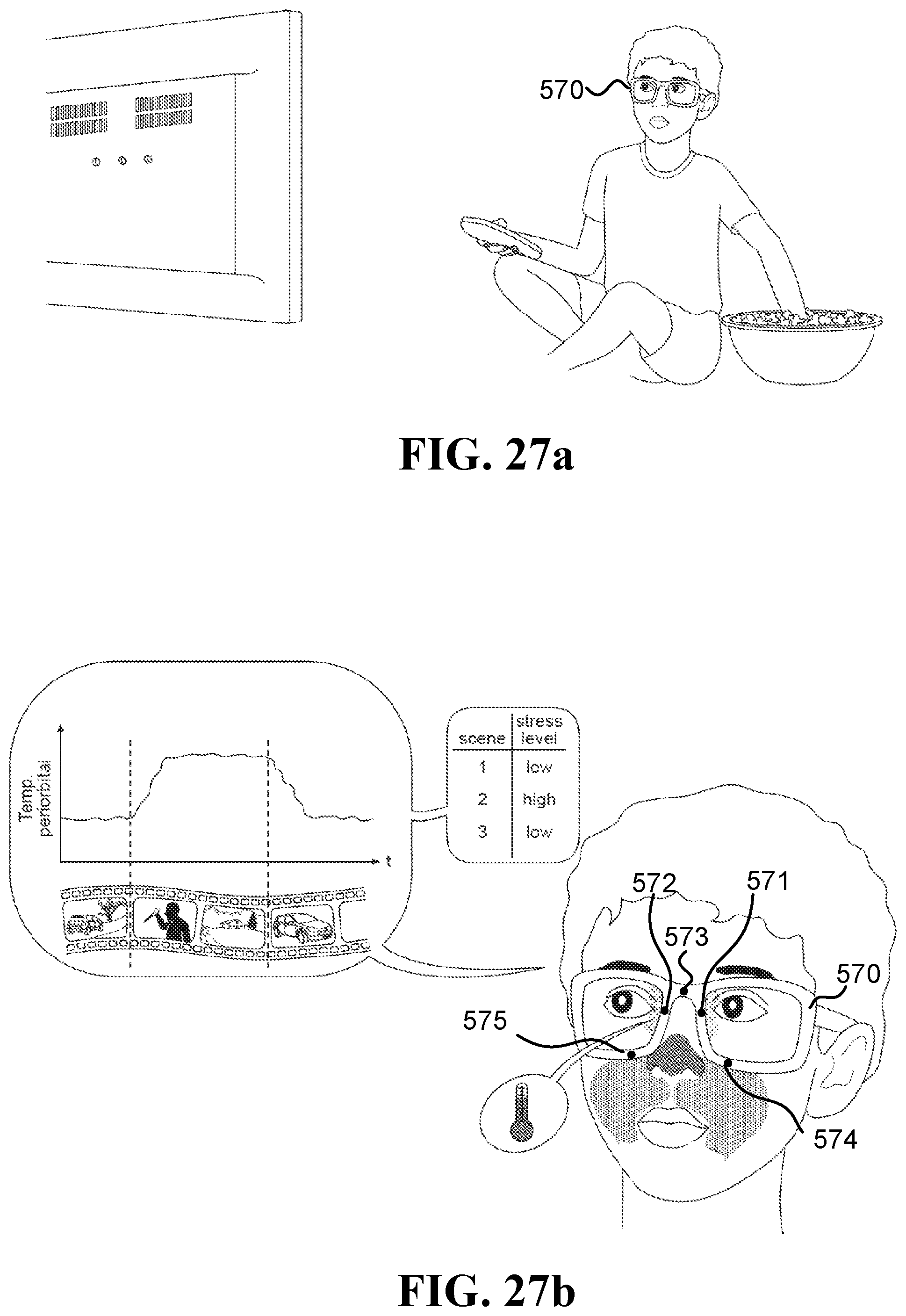
D00013
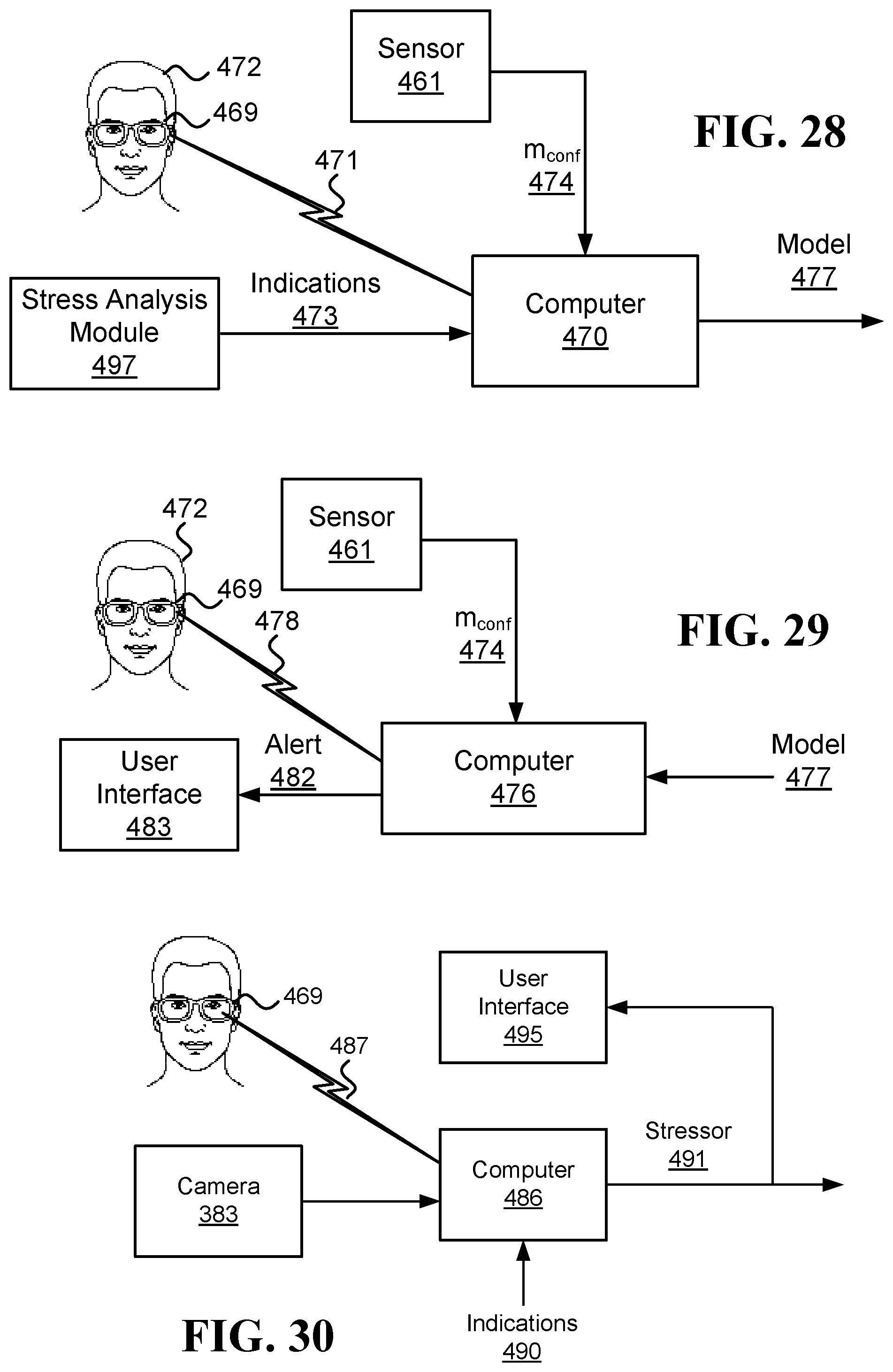
D00014

XML
uspto.report is an independent third-party trademark research tool that is not affiliated, endorsed, or sponsored by the United States Patent and Trademark Office (USPTO) or any other governmental organization. The information provided by uspto.report is based on publicly available data at the time of writing and is intended for informational purposes only.
While we strive to provide accurate and up-to-date information, we do not guarantee the accuracy, completeness, reliability, or suitability of the information displayed on this site. The use of this site is at your own risk. Any reliance you place on such information is therefore strictly at your own risk.
All official trademark data, including owner information, should be verified by visiting the official USPTO website at www.uspto.gov. This site is not intended to replace professional legal advice and should not be used as a substitute for consulting with a legal professional who is knowledgeable about trademark law.