Surgical fastener applying apparatus
Gupta , et al. Dec
U.S. patent number 10,517,588 [Application Number 15/667,660] was granted by the patent office on 2019-12-31 for surgical fastener applying apparatus. This patent grant is currently assigned to Covidien LP. The grantee listed for this patent is Covidien LP. Invention is credited to Richard Roland Bueno, Kiran Garikipati, Arvind Kumar Gupta, Nikhil R. Katre, Sekar Perumal, Rajesh T. Shelke, Cinish P. Varghese.


View All Diagrams
| United States Patent | 10,517,588 |
| Gupta , et al. | December 31, 2019 |
Surgical fastener applying apparatus
Abstract
A surgical fastener applying apparatus includes an anvil half-section and a cartridge-receiving half-section including an elongated channel member having a pair of opposed openings defined through sidewalls thereof. A disposable assembly including a single use loading unit and a single use firing unit is configured to be releasably supported within the cartridge-receiving half-section. The disposable assembly includes a stationary housing for supporting the firing unit which includes a distal extension for supporting the single use loading unit. The stationary housing includes a pair of flared tabs configured to be releasably received within the openings of the cartridge-receiving half-section to releasably engage the disposable assembly within the cartridge-receiving half-section.
| Inventors: | Gupta; Arvind Kumar (Uttar Pradesh, IN), Katre; Nikhil R. (Maharashtra, IN), Garikipati; Kiran (Andhra Pradesh, IN), Perumal; Sekar (Tamilnadu, IN), Shelke; Rajesh T. (Banglore, IN), Varghese; Cinish P. (Adimaly, IN), Bueno; Richard Roland (Madison, CT) | ||||||||||
|---|---|---|---|---|---|---|---|---|---|---|---|
| Applicant: |
|
||||||||||
| Assignee: | Covidien LP (Mansfield,
MA) |
||||||||||
| Family ID: | 46642648 | ||||||||||
| Appl. No.: | 15/667,660 | ||||||||||
| Filed: | August 3, 2017 |
Prior Publication Data
| Document Identifier | Publication Date | |
|---|---|---|
| US 20170325811 A1 | Nov 16, 2017 | |
Related U.S. Patent Documents
| Application Number | Filing Date | Patent Number | Issue Date | ||
|---|---|---|---|---|---|
| 13546974 | Jul 11, 2012 | 9724095 | |||
| 61521070 | Aug 8, 2011 | ||||
| Current U.S. Class: | 1/1 |
| Current CPC Class: | A61B 17/0643 (20130101); A61B 17/0684 (20130101); A61B 17/064 (20130101); A61B 17/07207 (20130101); A61B 17/068 (20130101); A61B 17/0682 (20130101); A61B 2560/0285 (20130101); A61B 2017/0023 (20130101); A61B 2017/00464 (20130101); A61B 2017/00473 (20130101); A61B 2090/0814 (20160201); A61B 17/0686 (20130101); A61B 2017/00668 (20130101); A61B 2090/08021 (20160201); A61B 2017/0688 (20130101); A61B 2017/00619 (20130101); A61B 2017/00659 (20130101); A61B 2017/07257 (20130101) |
| Current International Class: | A61B 17/064 (20060101); A61B 17/068 (20060101); A61B 17/072 (20060101); A61B 17/00 (20060101); A61B 90/00 (20160101) |
References Cited [Referenced By]
U.S. Patent Documents
| 3079606 | March 1963 | Bobrov et al. |
| 3490675 | January 1970 | Green et al. |
| 3499591 | March 1970 | Green |
| 3777538 | December 1973 | Weatherly et al. |
| 3882854 | May 1975 | Hulka et al. |
| 4027510 | June 1977 | Hiltebrandt |
| 4086926 | May 1978 | Green et al. |
| 4244372 | January 1981 | Kapitanov et al. |
| 4429695 | February 1984 | Green |
| 4505414 | March 1985 | Filipi |
| 4520817 | June 1985 | Green |
| 4550870 | November 1985 | Krumme et al. |
| 4589413 | May 1986 | Malyshev et al. |
| 4596351 | June 1986 | Fedotov et al. |
| 4602634 | July 1986 | Barkley |
| 4605001 | August 1986 | Rothfuss et al. |
| 4608981 | September 1986 | Rothfuss et al. |
| 4610383 | September 1986 | Rothfuss et al. |
| 4633861 | January 1987 | Chow |
| 4633874 | January 1987 | Chow et al. |
| 4671445 | June 1987 | Barker et al. |
| 4700703 | October 1987 | Resnick et al. |
| 4703887 | November 1987 | Clanton et al. |
| 4728020 | March 1988 | Green et al. |
| 4752024 | June 1988 | Green et al. |
| 4784137 | November 1988 | Kulik et al. |
| 4863088 | September 1989 | Redmond et al. |
| 4869415 | September 1989 | Fox |
| 4892244 | January 1990 | Fox |
| 4955959 | September 1990 | Tompkins et al. |
| 4978049 | December 1990 | Green |
| 4991764 | February 1991 | Mericle |
| 5014899 | May 1991 | Presty et al. |
| 5031814 | July 1991 | Tompkins et al. |
| 5040715 | August 1991 | Green et al. |
| 5065929 | November 1991 | Schulze et al. |
| 5071430 | December 1991 | de Salis et al. |
| 5074454 | December 1991 | Peters |
| 5083695 | January 1992 | Foslien et al. |
| 5084057 | January 1992 | Green et al. |
| 5106008 | April 1992 | Tompkins et al. |
| 5111987 | May 1992 | Moeinzadeh et al. |
| 5129570 | July 1992 | Schulze |
| 5141144 | August 1992 | Foslien et al. |
| 5156315 | October 1992 | Green et al. |
| 5156614 | October 1992 | Green et al. |
| 5163943 | November 1992 | Mohiuddin et al. |
| 5170925 | December 1992 | Madden et al. |
| 5171247 | December 1992 | Hughett et al. |
| 5173133 | December 1992 | Morin et al. |
| 5180092 | January 1993 | Crainich |
| 5188274 | February 1993 | Moeinzadeh et al. |
| 5220928 | June 1993 | Oddsen et al. |
| 5221036 | June 1993 | Takase |
| 5242457 | September 1993 | Akopov et al. |
| 5246156 | September 1993 | Rothfuss et al. |
| 5253793 | October 1993 | Green et al. |
| 5263629 | November 1993 | Trumbull et al. |
| RE34519 | January 1994 | Fox et al. |
| 5275323 | January 1994 | Schulze et al. |
| 5282807 | February 1994 | Knoepfler |
| 5289963 | March 1994 | McGarry et al. |
| 5307976 | May 1994 | Olson et al. |
| 5308576 | May 1994 | Green et al. |
| 5312023 | May 1994 | Green et al. |
| 5318221 | June 1994 | Green et al. |
| 5326013 | July 1994 | Green et al. |
| 5328077 | July 1994 | Lou |
| 5330486 | July 1994 | Wilk |
| 5332142 | July 1994 | Robinson et al. |
| 5336232 | August 1994 | Green et al. |
| 5344061 | September 1994 | Crainich |
| 5352238 | October 1994 | Green et al. |
| 5356064 | October 1994 | Green et al. |
| 5358506 | October 1994 | Green et al. |
| 5364001 | November 1994 | Bryan |
| 5364002 | November 1994 | Green et al. |
| 5364003 | November 1994 | Williamson, IV |
| 5366133 | November 1994 | Geiste |
| 5376095 | December 1994 | Ortiz |
| 5379933 | January 1995 | Green et al. |
| 5381943 | January 1995 | Allen et al. |
| 5382255 | January 1995 | Castro et al. |
| 5383880 | January 1995 | Hooven |
| 5389098 | February 1995 | Tsuruta et al. |
| 5395033 | March 1995 | Byrne et al. |
| 5395034 | March 1995 | Allen |
| 5397046 | March 1995 | Savage et al. |
| 5397324 | March 1995 | Carroll et al. |
| 5403312 | April 1995 | Yates et al. |
| 5405072 | April 1995 | Zlock et al. |
| 5407293 | April 1995 | Crainich |
| 5413268 | May 1995 | Green |
| 5415334 | May 1995 | Williamson et al. |
| 5415335 | May 1995 | Knodell, Jr. |
| 5417361 | May 1995 | Williamson, IV |
| 5423471 | June 1995 | Mastri et al. |
| 5425745 | June 1995 | Green et al. |
| 5431322 | July 1995 | Green et al. |
| 5431323 | July 1995 | Smith et al. |
| 5433721 | July 1995 | Hooven et al. |
| 5441193 | August 1995 | Gravener |
| 5445304 | August 1995 | Plyley et al. |
| 5447265 | September 1995 | Vidal et al. |
| 5452837 | September 1995 | Williamson, IV et al. |
| 5456401 | October 1995 | Green et al. |
| 5464300 | November 1995 | Crainich |
| 5465895 | November 1995 | Knodel et al. |
| 5467911 | November 1995 | Tsuruta et al. |
| 5470007 | November 1995 | Plyley et al. |
| 5470010 | November 1995 | Rothfuss et al. |
| 5472132 | December 1995 | Savage et al. |
| 5474566 | December 1995 | Alesi et al. |
| 5476206 | December 1995 | Green et al. |
| 5478003 | December 1995 | Green |
| 5480089 | January 1996 | Blewett |
| 5482197 | January 1996 | Green et al. |
| 5484095 | January 1996 | Green et al. |
| 5484451 | January 1996 | Akopov et al. |
| 5485947 | January 1996 | Olson et al. |
| 5485952 | January 1996 | Fontayne |
| 5486185 | January 1996 | Freitas et al. |
| 5487499 | January 1996 | Sorrentino et al. |
| 5487500 | January 1996 | Knodel et al. |
| 5489058 | February 1996 | Plyley et al. |
| 5490856 | February 1996 | Person et al. |
| 5497933 | March 1996 | DeFonzo et al. |
| 5501689 | March 1996 | Green et al. |
| 5505363 | April 1996 | Green et al. |
| 5507426 | April 1996 | Young et al. |
| 5518163 | May 1996 | Hooven |
| 5518164 | May 1996 | Hooven |
| 5529235 | June 1996 | Boiarski et al. |
| 5531744 | July 1996 | Nardella et al. |
| 5535934 | July 1996 | Boiarski et al. |
| 5535935 | July 1996 | Vidal et al. |
| 5535937 | July 1996 | Boiarski et al. |
| 5540375 | July 1996 | Bolanos et al. |
| 5542594 | August 1996 | McKean et al. |
| 5549628 | August 1996 | Cooper et al. |
| 5551622 | September 1996 | Yoon |
| 5553765 | September 1996 | Knodel et al. |
| 5554164 | September 1996 | Wilson et al. |
| 5554169 | September 1996 | Green et al. |
| 5560530 | October 1996 | Bolanos et al. |
| 5560532 | October 1996 | DeFonzo et al. |
| 5562239 | October 1996 | Boiarski et al. |
| 5562241 | October 1996 | Knodel et al. |
| 5562682 | October 1996 | Oberlin et al. |
| 5562701 | October 1996 | Huitema et al. |
| 5564615 | October 1996 | Bishop et al. |
| 5571116 | November 1996 | Bolanos et al. |
| 5573169 | November 1996 | Green et al. |
| 5573543 | November 1996 | Akopov et al. |
| 5575799 | November 1996 | Bolanos et al. |
| 5575803 | November 1996 | Cooper et al. |
| 5577654 | November 1996 | Bishop |
| 5579107 | November 1996 | Wright et al. |
| 5584425 | December 1996 | Savage et al. |
| 5586711 | December 1996 | Plyley et al. |
| 5588580 | December 1996 | Paul et al. |
| 5588581 | December 1996 | Conlon et al. |
| 5597107 | January 1997 | Knodel et al. |
| 5601224 | February 1997 | Bishop et al. |
| 5607095 | March 1997 | Smith et al. |
| 5615820 | April 1997 | Viola |
| 5618291 | April 1997 | Thompson et al. |
| 5624452 | April 1997 | Yates |
| 5626587 | May 1997 | Bishop et al. |
| 5628446 | May 1997 | Geiste et al. |
| 5630539 | May 1997 | Plyley et al. |
| 5630540 | May 1997 | Blewett |
| 5630541 | May 1997 | Williamson, IV et al. |
| 5632432 | May 1997 | Schulze et al. |
| 5634584 | June 1997 | Okorocha et al. |
| 5636779 | June 1997 | Palmer |
| 5636780 | June 1997 | Green et al. |
| 5645209 | July 1997 | Green et al. |
| 5647526 | July 1997 | Green et al. |
| 5651491 | July 1997 | Heaton |
| 5653373 | August 1997 | Green et al. |
| 5653374 | August 1997 | Young et al. |
| 5653721 | August 1997 | Knodel et al. |
| 5655698 | August 1997 | Yoon |
| 5657921 | August 1997 | Young et al. |
| 5658300 | August 1997 | Bito et al. |
| 5662258 | September 1997 | Knodel et al. |
| 5662259 | September 1997 | Yoon |
| 5662260 | September 1997 | Yoon |
| 5662662 | September 1997 | Bishop et al. |
| 5662666 | September 1997 | Onuki et al. |
| 5665085 | September 1997 | Nardella |
| 5667517 | September 1997 | Hooven |
| 5669544 | September 1997 | Schulze et al. |
| 5673840 | October 1997 | Schulze et al. |
| 5673841 | October 1997 | Schulze et al. |
| 5673842 | October 1997 | Bittner et al. |
| 5676674 | October 1997 | Bolanos et al. |
| 5680981 | October 1997 | Mililli et al. |
| 5680982 | October 1997 | Schulze et al. |
| 5680983 | October 1997 | Plyley et al. |
| 5690269 | November 1997 | Bolanos et al. |
| 5692668 | December 1997 | Schulze et al. |
| 5697542 | December 1997 | Knodel et al. |
| 5702409 | December 1997 | Rayburn et al. |
| 5704534 | January 1998 | Huitema et al. |
| 5706997 | January 1998 | Green et al. |
| 5709334 | January 1998 | Sorrentino et al. |
| 5711472 | January 1998 | Bryan |
| 5713505 | February 1998 | Huitema |
| 5715988 | February 1998 | Palmer |
| 5716366 | February 1998 | Yates |
| 5718359 | February 1998 | Palmer et al. |
| 5725536 | March 1998 | Oberlin et al. |
| 5725554 | March 1998 | Simon et al. |
| 5728110 | March 1998 | Vidal et al. |
| 5732806 | March 1998 | Foshee et al. |
| 5735848 | April 1998 | Yates et al. |
| 5743456 | April 1998 | Jones et al. |
| 5749893 | May 1998 | Vidal et al. |
| 5752644 | May 1998 | Bolanos et al. |
| 5762255 | June 1998 | Chrisman et al. |
| 5762256 | June 1998 | Mastri et al. |
| 5769303 | June 1998 | Knodel et al. |
| 5769892 | June 1998 | Kingwell |
| 5772099 | June 1998 | Gravener |
| 5772673 | June 1998 | Cuny et al. |
| 5779130 | July 1998 | Alesi et al. |
| 5779131 | July 1998 | Knodel et al. |
| 5779132 | July 1998 | Knodel et al. |
| 5782396 | July 1998 | Mastri |
| 5782397 | July 1998 | Koukline |
| 5782834 | July 1998 | Lucey et al. |
| 5785232 | July 1998 | Vidal et al. |
| 5797536 | August 1998 | Smith et al. |
| 5797537 | August 1998 | Oberlin et al. |
| 5797538 | August 1998 | Heaton et al. |
| 5810811 | September 1998 | Yates et al. |
| 5810855 | September 1998 | Rayburn et al. |
| 5814055 | September 1998 | Knodel et al. |
| 5814057 | September 1998 | Oi et al. |
| 5816471 | October 1998 | Plyley et al. |
| 5817109 | October 1998 | McGarry et al. |
| 5820009 | October 1998 | Melling et al. |
| 5823066 | October 1998 | Huitema et al. |
| 5826776 | October 1998 | Schulze et al. |
| 5829662 | November 1998 | Allen et al. |
| 5833695 | November 1998 | Yoon |
| 5836147 | November 1998 | Schnipke |
| 5862972 | January 1999 | Green et al. |
| 5865361 | February 1999 | Milliman et al. |
| 5871135 | February 1999 | Williamson, IV et al. |
| 5873873 | February 1999 | Smith et al. |
| 5878938 | March 1999 | Bittner et al. |
| 5893506 | April 1999 | Powell |
| 5894979 | April 1999 | Powell |
| 5897562 | April 1999 | Bolanos et al. |
| 5901895 | May 1999 | Heaton et al. |
| 5911352 | June 1999 | Racenet et al. |
| 5911353 | June 1999 | Bolanos et al. |
| 5918791 | July 1999 | Sorrentino et al. |
| 5919198 | July 1999 | Graves, Jr. et al. |
| 5922001 | July 1999 | Yoon |
| 5931847 | August 1999 | Bittner et al. |
| 5941442 | August 1999 | Geiste et al. |
| 5954259 | September 1999 | Viola et al. |
| 5964774 | October 1999 | McKean et al. |
| 5980510 | November 1999 | Tsonton et al. |
| 5988479 | November 1999 | Palmer |
| 6004335 | December 1999 | Vaitekunas et al. |
| 6010054 | January 2000 | Johnson et al. |
| 6032849 | March 2000 | Mastri et al. |
| 6045560 | April 2000 | McKean et al. |
| 6063097 | May 2000 | Oi et al. |
| 6066144 | May 2000 | Wolf et al. |
| 6079606 | June 2000 | Milliman et al. |
| 6099551 | August 2000 | Gabbay |
| 6109500 | August 2000 | Alli et al. |
| 6131789 | October 2000 | Schulze et al. |
| 6131790 | October 2000 | Piraka |
| 6155473 | December 2000 | Tompkins et al. |
| 6197017 | March 2001 | Brock et al. |
| 6202914 | March 2001 | Geiste et al. |
| 6241139 | June 2001 | Milliman et al. |
| 6250532 | June 2001 | Green et al. |
| 6264086 | July 2001 | McGuckin, Jr. |
| 6264087 | July 2001 | Whitman |
| 6269977 | August 2001 | Moore |
| 6279809 | August 2001 | Nicolo |
| 6315183 | November 2001 | Piraka |
| 6315184 | November 2001 | Whitman |
| 6325810 | December 2001 | Hamilton et al. |
| 6330965 | December 2001 | Milliman et al. |
| 6391038 | May 2002 | Vargas et al. |
| 6398797 | June 2002 | Bombard et al. |
| 6436097 | August 2002 | Nardella |
| 6439446 | August 2002 | Perry et al. |
| 6443973 | September 2002 | Whitman |
| 6463623 | October 2002 | Ahn et al. |
| 6478804 | November 2002 | Vargas et al. |
| 6488196 | December 2002 | Fenton, Jr. |
| 6503257 | January 2003 | Grant et al. |
| 6505768 | January 2003 | Whitman |
| 6544274 | April 2003 | Danitz et al. |
| 6554844 | April 2003 | Lee et al. |
| 6565554 | May 2003 | Niemeyer |
| 6587750 | July 2003 | Gerbi et al. |
| 6592597 | July 2003 | Grant et al. |
| 6594552 | July 2003 | Nowlin et al. |
| 6602252 | August 2003 | Mollenauer |
| 6612053 | September 2003 | Liao |
| 6619529 | September 2003 | Green et al. |
| D480808 | October 2003 | Wells et al. |
| 6644532 | November 2003 | Green et al. |
| 6656193 | December 2003 | Grant et al. |
| 6669073 | December 2003 | Milliman et al. |
| 6681978 | January 2004 | Geiste et al. |
| 6698643 | March 2004 | Whitman |
| 6716232 | April 2004 | Vidal et al. |
| 6722552 | April 2004 | Fenton, Jr. |
| 6731473 | May 2004 | Li et al. |
| 6755338 | June 2004 | Hahnen et al. |
| 6783524 | August 2004 | Anderson et al. |
| 6786382 | September 2004 | Hoffman |
| 6808262 | October 2004 | Chapoy et al. |
| 6817509 | November 2004 | Geiste et al. |
| 6830174 | December 2004 | Hillstead et al. |
| 6835199 | December 2004 | McGuckin, Jr. et al. |
| 6843403 | January 2005 | Whitman |
| RE38708 | March 2005 | Bolanos et al. |
| 6877647 | April 2005 | Green et al. |
| 6879880 | April 2005 | Nowlin et al. |
| 6889116 | May 2005 | Jinno |
| 6905057 | June 2005 | Swayze et al. |
| 6945444 | September 2005 | Gresham et al. |
| 6953138 | October 2005 | Dworak et al. |
| 6953139 | October 2005 | Milliman et al. |
| 6959852 | November 2005 | Shelton, IV et al. |
| 6962594 | November 2005 | Thevenet |
| 6964363 | November 2005 | Wales et al. |
| 6978921 | December 2005 | Shelton, IV et al. |
| 6981628 | January 2006 | Wales |
| 6986451 | January 2006 | Mastri et al. |
| 6988649 | January 2006 | Shelton, IV et al. |
| 6991627 | January 2006 | Madhani et al. |
| 6994714 | February 2006 | Vargas et al. |
| 7000818 | February 2006 | Shelton, IV et al. |
| 7000819 | February 2006 | Swayze et al. |
| 7032799 | April 2006 | Viola et al. |
| 7044352 | May 2006 | Shelton, IV et al. |
| 7044353 | May 2006 | Mastri et al. |
| 7055730 | June 2006 | Ehrenfels |
| 7055731 | June 2006 | Shelton, IV et al. |
| 7059508 | June 2006 | Shelton, IV et al. |
| 7070083 | July 2006 | Jankowski |
| 7083075 | August 2006 | Swayze et al. |
| 7097089 | August 2006 | Marczyk |
| 7111769 | September 2006 | Wales et al. |
| 7114642 | October 2006 | Whitman |
| 7121446 | October 2006 | Arad et al. |
| 7128253 | October 2006 | Mastri et al. |
| 7128254 | October 2006 | Shelton, IV et al. |
| 7140527 | November 2006 | Ehrenfels et al. |
| 7140528 | November 2006 | Shelton, IV |
| 7143923 | December 2006 | Shelton, IV et al. |
| 7143924 | December 2006 | Scirica et al. |
| 7143925 | December 2006 | Shelton, IV et al. |
| 7143926 | December 2006 | Shelton, IV et al. |
| 7147138 | December 2006 | Shelton, IV |
| 7159750 | January 2007 | Racenet et al. |
| 7168604 | January 2007 | Milliman et al. |
| 7172104 | February 2007 | Scirica et al. |
| 7188758 | March 2007 | Viola et al. |
| 7207471 | April 2007 | Heinrich et al. |
| 7213736 | May 2007 | Wales et al. |
| 7225963 | June 2007 | Scirica |
| 7225964 | June 2007 | Mastri et al. |
| 7238195 | July 2007 | Viola |
| 7246734 | July 2007 | Shelton, IV |
| 7258262 | August 2007 | Mastri et al. |
| 7278562 | October 2007 | Mastri et al. |
| 7278563 | October 2007 | Green |
| 7287682 | October 2007 | Ezzat et al. |
| 7293685 | November 2007 | Ehrenfels et al. |
| 7296722 | November 2007 | Ivanko |
| 7296724 | November 2007 | Green et al. |
| 7296772 | November 2007 | Wang |
| 7300444 | November 2007 | Nielsen et al. |
| 7303107 | December 2007 | Milliman et al. |
| 7303108 | December 2007 | Shelton, IV |
| 7308998 | December 2007 | Mastri et al. |
| 7326232 | February 2008 | Viola et al. |
| 7328828 | February 2008 | Ortiz et al. |
| 7328829 | February 2008 | Arad et al. |
| 7334717 | February 2008 | Rethy et al. |
| 7354447 | April 2008 | Shelton, IV et al. |
| 7357287 | April 2008 | Shelton, IV et al. |
| 7364061 | April 2008 | Swayze et al. |
| 7367485 | May 2008 | Shelton, IV et al. |
| 7377928 | May 2008 | Zubik et al. |
| 7380695 | June 2008 | Doll et al. |
| 7380696 | June 2008 | Shelton, IV et al. |
| 7396356 | July 2008 | Mollenauer |
| 7398907 | July 2008 | Racenet et al. |
| 7399310 | July 2008 | Edoga et al. |
| 7401720 | July 2008 | Durrani |
| 7401721 | July 2008 | Holsten et al. |
| 7404508 | July 2008 | Smith et al. |
| 7404509 | July 2008 | Ortiz et al. |
| 7407074 | August 2008 | Ortiz et al. |
| 7407075 | August 2008 | Holsten et al. |
| 7407077 | August 2008 | Ortiz et al. |
| 7407078 | August 2008 | Shelton, IV et al. |
| 7416101 | August 2008 | Shelton, IV et al. |
| 7419080 | September 2008 | Smith et al. |
| 7419081 | September 2008 | Ehrenfels et al. |
| 7419495 | September 2008 | Menn et al. |
| 7422139 | September 2008 | Shelton, IV et al. |
| 7424965 | September 2008 | Racenet et al. |
| 7431189 | October 2008 | Shelton, IV et al. |
| 7431730 | October 2008 | Viola |
| 7434715 | October 2008 | Shelton, IV et al. |
| 7434717 | October 2008 | Shelton, IV et al. |
| 7438208 | October 2008 | Larson |
| 7438209 | October 2008 | Hess et al. |
| 7441684 | October 2008 | Shelton, IV et al. |
| 7441685 | October 2008 | Boudreaux |
| 7448525 | November 2008 | Shelton, IV et al. |
| 7451904 | November 2008 | Shelton, IV |
| 7455208 | November 2008 | Wales et al. |
| 7455676 | November 2008 | Holsten et al. |
| 7458494 | December 2008 | Matsutani et al. |
| 7461767 | December 2008 | Viola et al. |
| 7462185 | December 2008 | Knodel |
| 7464846 | December 2008 | Shelton, IV et al. |
| 7464847 | December 2008 | Viola et al. |
| 7464848 | December 2008 | Green et al. |
| 7464849 | December 2008 | Shelton, IV et al. |
| 7467740 | December 2008 | Shelton, IV et al. |
| 7472814 | January 2009 | Mastri et al. |
| 7472815 | January 2009 | Shelton, IV et al. |
| 7472816 | January 2009 | Holsten et al. |
| 7473258 | January 2009 | Clauson et al. |
| 7481347 | January 2009 | Roy |
| 7481348 | January 2009 | Marczyk |
| 7481349 | January 2009 | Holsten et al. |
| 7481824 | January 2009 | Boudreaux et al. |
| 7487899 | February 2009 | Shelton, IV et al. |
| 7490749 | February 2009 | Schall et al. |
| 7494039 | February 2009 | Racenet et al. |
| 7500979 | March 2009 | Hueil et al. |
| 7503474 | March 2009 | Hillstead et al. |
| 7506790 | March 2009 | Shelton, IV |
| 7506791 | March 2009 | Omaits et al. |
| 7510107 | March 2009 | Timm et al. |
| 7513408 | April 2009 | Shelton, IV et al. |
| 7517356 | April 2009 | Heinrich |
| 7537602 | May 2009 | Whitman |
| 7543729 | June 2009 | Ivanko |
| 7543730 | June 2009 | Marczyk |
| 7543731 | June 2009 | Green et al. |
| 7552854 | June 2009 | Wixey et al. |
| 7556185 | July 2009 | Viola |
| 7556186 | July 2009 | Milliman |
| 7559450 | July 2009 | Wales et al. |
| 7559452 | July 2009 | Wales et al. |
| 7559453 | July 2009 | Heinrich et al. |
| 7559937 | July 2009 | de la Torre et al. |
| 7565993 | July 2009 | Milliman et al. |
| 7568603 | August 2009 | Shelton, IV et al. |
| 7568604 | August 2009 | Ehrenfels et al. |
| 7571845 | August 2009 | Viola |
| 7575144 | August 2009 | Ortiz et al. |
| 7584880 | September 2009 | Racenet et al. |
| 7588174 | September 2009 | Holsten et al. |
| 7588175 | September 2009 | Timm et al. |
| 7588176 | September 2009 | Timm et al. |
| 7588177 | September 2009 | Racenet |
| 7597229 | October 2009 | Boudreaux et al. |
| 7597230 | October 2009 | Racenet et al. |
| 7600663 | October 2009 | Green |
| 7604150 | October 2009 | Boudreaux |
| 7604151 | October 2009 | Hess et al. |
| 7607557 | October 2009 | Shelton, IV et al. |
| 7611038 | November 2009 | Racenet et al. |
| 7617961 | November 2009 | Viola |
| 7624902 | December 2009 | Marczyk et al. |
| 7624903 | December 2009 | Green et al. |
| 7631793 | December 2009 | Rethy et al. |
| 7631794 | December 2009 | Rethy et al. |
| 7635073 | December 2009 | Heinrich |
| 7635074 | December 2009 | Olson et al. |
| 7635373 | December 2009 | Ortiz |
| 7637409 | December 2009 | Marczyk |
| 7637410 | December 2009 | Marczyk |
| 7641091 | January 2010 | Olson et al. |
| 7641093 | January 2010 | Doll et al. |
| 7641095 | January 2010 | Viola |
| 7644848 | January 2010 | Swayze et al. |
| 7648055 | January 2010 | Marczyk |
| 7651017 | January 2010 | Ortiz et al. |
| 7654431 | February 2010 | Hueil et al. |
| 7658311 | February 2010 | Boudreaux |
| 7658312 | February 2010 | Vidal et al. |
| 7665646 | February 2010 | Prommersberger |
| 7665647 | February 2010 | Shelton, IV et al. |
| 7669746 | March 2010 | Shelton, IV |
| 7670334 | March 2010 | Hueil et al. |
| 7673780 | March 2010 | Shelton, IV et al. |
| 7673781 | March 2010 | Swayze et al. |
| 7673782 | March 2010 | Hess et al. |
| 7673783 | March 2010 | Morgan et al. |
| 7678121 | March 2010 | Knodel |
| 7681772 | March 2010 | Green et al. |
| 7682367 | March 2010 | Shah et al. |
| 7682368 | March 2010 | Bombard et al. |
| 7690547 | April 2010 | Racenet et al. |
| 7694865 | April 2010 | Scirica |
| 7699205 | April 2010 | Ivanko |
| 7703653 | April 2010 | Shah et al. |
| 7721930 | May 2010 | McKenna et al. |
| 7721931 | May 2010 | Shelton, IV et al. |
| 7721933 | May 2010 | Ehrenfels et al. |
| 7721935 | May 2010 | Racenet et al. |
| 7726537 | June 2010 | Olson et al. |
| 7726538 | June 2010 | Holsten et al. |
| 7726539 | June 2010 | Holsten et al. |
| 7731072 | June 2010 | Timm et al. |
| 7735703 | June 2010 | Morgan et al. |
| 7740159 | June 2010 | Shelton, IV et al. |
| 7740160 | June 2010 | Viola |
| 7743960 | June 2010 | Whitman et al. |
| 7744628 | June 2010 | Viola |
| 7753245 | July 2010 | Boudreaux et al. |
| 7753248 | July 2010 | Viola |
| 7757924 | July 2010 | Gerbi et al. |
| 7757925 | July 2010 | Viola et al. |
| 7762445 | July 2010 | Heinrich et al. |
| 7766209 | August 2010 | Baxter, III et al. |
| 7766210 | August 2010 | Shelton, IV et al. |
| 7766924 | August 2010 | Bombard et al. |
| 7766928 | August 2010 | Ezzat et al. |
| 7770774 | August 2010 | Mastri et al. |
| 7770775 | August 2010 | Shelton, IV et al. |
| 7776060 | August 2010 | Mooradian et al. |
| 7780055 | August 2010 | Scirica et al. |
| 7784662 | August 2010 | Wales et al. |
| 7789283 | September 2010 | Shah |
| 7789889 | September 2010 | Zubik et al. |
| 7793812 | September 2010 | Moore et al. |
| 7793814 | September 2010 | Racenet et al. |
| 7794475 | September 2010 | Hess et al. |
| 7798385 | September 2010 | Boyden et al. |
| 7798386 | September 2010 | Schall et al. |
| 7799039 | September 2010 | Shelton, IV et al. |
| 7810690 | October 2010 | Bilotti et al. |
| 7810691 | October 2010 | Boyden et al. |
| 7810692 | October 2010 | Hall et al. |
| 7810693 | October 2010 | Broehl et al. |
| 7815090 | October 2010 | Marczyk |
| 7815091 | October 2010 | Marczyk |
| 7815092 | October 2010 | Whitman et al. |
| 7819296 | October 2010 | Hueil et al. |
| 7819297 | October 2010 | Doll et al. |
| 7819298 | October 2010 | Hall et al. |
| 7819299 | October 2010 | Shelton, IV et al. |
| 7819896 | October 2010 | Racenet |
| 7823760 | November 2010 | Zemlok et al. |
| 7823761 | November 2010 | Boyden et al. |
| 7824426 | November 2010 | Racenet et al. |
| 7828186 | November 2010 | Wales |
| 7828187 | November 2010 | Green et al. |
| 7828188 | November 2010 | Jankowski |
| 7828189 | November 2010 | Holsten et al. |
| 7832408 | November 2010 | Shelton, IV et al. |
| 7832611 | November 2010 | Boyden et al. |
| 7832612 | November 2010 | Baxter, III et al. |
| 7837079 | November 2010 | Holsten et al. |
| 7837081 | November 2010 | Holsten et al. |
| 7841503 | November 2010 | Sonnenschein et al. |
| 7845533 | December 2010 | Marczyk et al. |
| 7845534 | December 2010 | Viola et al. |
| 7845535 | December 2010 | Scircia |
| 7845537 | December 2010 | Shelton, IV et al. |
| 7845538 | December 2010 | Whitman |
| 7850703 | December 2010 | Bombard et al. |
| 7857183 | December 2010 | Shelton, IV |
| 7857184 | December 2010 | Viola |
| 7857185 | December 2010 | Swayze et al. |
| 7857186 | December 2010 | Baxter, III et al. |
| 7861906 | January 2011 | Doll et al. |
| 7861907 | January 2011 | Green et al. |
| 7866524 | January 2011 | Krehel |
| 7866525 | January 2011 | Scirica |
| 7866526 | January 2011 | Green et al. |
| 7866527 | January 2011 | Hall et al. |
| 7866528 | January 2011 | Olson et al. |
| 7870989 | January 2011 | Viola et al. |
| 7886952 | February 2011 | Scirica et al. |
| 7891532 | February 2011 | Mastri et al. |
| 7891533 | February 2011 | Green et al. |
| 7891534 | February 2011 | Wenchell et al. |
| 7896214 | March 2011 | Farascioni |
| 7900805 | March 2011 | Shelton, IV et al. |
| 7901416 | March 2011 | Nolan et al. |
| 7905380 | March 2011 | Shelton, IV et al. |
| 7905381 | March 2011 | Baxter, III et al. |
| 7909039 | March 2011 | Hur |
| 7909220 | March 2011 | Viola |
| 7909221 | March 2011 | Viola et al. |
| 7909224 | March 2011 | Prommersberger |
| 7913891 | March 2011 | Doll et al. |
| 7913893 | March 2011 | Mastri et al. |
| 7914543 | March 2011 | Roth et al. |
| 7918230 | April 2011 | Whitman et al. |
| 7918276 | April 2011 | Guignard et al. |
| 7922061 | April 2011 | Shelton, IV et al. |
| 7922063 | April 2011 | Zemlok et al. |
| 7922064 | April 2011 | Boyden et al. |
| 7926691 | April 2011 | Viola et al. |
| 7926692 | April 2011 | Racenet et al. |
| 7934628 | May 2011 | Wenchell et al. |
| 7934630 | May 2011 | Shelton, IV et al. |
| 7934631 | May 2011 | Balbierz et al. |
| 7942300 | May 2011 | Rethy et al. |
| 7942303 | May 2011 | Shah |
| 7950560 | May 2011 | Zemlok et al. |
| 7950561 | May 2011 | Aranyi |
| 7950562 | May 2011 | Beardsley et al. |
| 7954682 | June 2011 | Giordano et al. |
| 7954683 | June 2011 | Knodel et al. |
| 7954684 | June 2011 | Boudreaux |
| 7954685 | June 2011 | Viola |
| 7954686 | June 2011 | Baxter, III et al. |
| 7954687 | June 2011 | Zemlok et al. |
| 7959051 | June 2011 | Smith et al. |
| 7963431 | June 2011 | Scirica |
| 7963432 | June 2011 | Knodel et al. |
| 7963433 | June 2011 | Whitman et al. |
| 7967178 | June 2011 | Scirica et al. |
| 7967179 | June 2011 | Olson et al. |
| 7967180 | June 2011 | Scirica |
| 7975894 | July 2011 | Boyden et al. |
| 7980443 | July 2011 | Scheib et al. |
| 7988026 | August 2011 | Knodel et al. |
| 7988027 | August 2011 | Olson et al. |
| 7988028 | August 2011 | Farascioni et al. |
| 7992758 | August 2011 | Whitman et al. |
| 7997468 | August 2011 | Farascioni |
| 7997469 | August 2011 | Olson et al. |
| 8002795 | August 2011 | Beetel |
| 8006885 | August 2011 | Marczyk |
| 8006887 | August 2011 | Marczyk |
| 8007505 | August 2011 | Weller et al. |
| 8007513 | August 2011 | Nalagatla et al. |
| 8011550 | September 2011 | Aranyi et al. |
| 8011551 | September 2011 | Marczyk et al. |
| 8011552 | September 2011 | Ivanko |
| 8011553 | September 2011 | Mastri et al. |
| 8011555 | September 2011 | Tarinelli et al. |
| 8012170 | September 2011 | Whitman et al. |
| 8015976 | September 2011 | Shah |
| 8016177 | September 2011 | Bettuchi et al. |
| 8016178 | September 2011 | Olson et al. |
| 8020742 | September 2011 | Marczyk |
| 8020743 | September 2011 | Shelton, IV |
| 8028882 | October 2011 | Viola |
| 8028883 | October 2011 | Stopek |
| 8028884 | October 2011 | Sniffin et al. |
| 8033438 | October 2011 | Scirica |
| 8033440 | October 2011 | Wenchell et al. |
| 8033441 | October 2011 | Marczyk |
| 8033442 | October 2011 | Racenet et al. |
| 8034077 | October 2011 | Smith et al. |
| 8038044 | October 2011 | Viola |
| 8038045 | October 2011 | Bettuchi et al. |
| 8052024 | November 2011 | Viola et al. |
| 8056787 | November 2011 | Boudreaux et al. |
| 8056788 | November 2011 | Mastri et al. |
| 8056791 | November 2011 | Whitman |
| 8061577 | November 2011 | Racenet et al. |
| 8066166 | November 2011 | Demmy et al. |
| 8070033 | December 2011 | Milliman et al. |
| 8070035 | December 2011 | Holsten et al. |
| 8074858 | December 2011 | Marczyk |
| 8074859 | December 2011 | Kostrzewski |
| 8074862 | December 2011 | Shah |
| 8083118 | December 2011 | Milliman et al. |
| 8083119 | December 2011 | Prommersberger |
| 8083120 | December 2011 | Shelton, IV et al. |
| 8087563 | January 2012 | Milliman et al. |
| 8091753 | January 2012 | Viola |
| 8091754 | January 2012 | Ehrenfels et al. |
| 8091756 | January 2012 | Viola |
| 8096459 | January 2012 | Ortiz et al. |
| 8096460 | January 2012 | Blier et al. |
| 8100309 | January 2012 | Marczyk |
| 8100310 | January 2012 | Zemlok |
| 8113406 | February 2012 | Holsten et al. |
| 8113407 | February 2012 | Holsten et al. |
| 8113408 | February 2012 | Wenchell et al. |
| 8113409 | February 2012 | Cohen et al. |
| 8113410 | February 2012 | Hall et al. |
| 8123101 | February 2012 | Racenet et al. |
| 8127975 | March 2012 | Olson et al. |
| 8127976 | March 2012 | Scirica et al. |
| 8132703 | March 2012 | Milliman et al. |
| 8132705 | March 2012 | Viola et al. |
| 8132706 | March 2012 | Marczyk et al. |
| 8136713 | March 2012 | Hathaway et al. |
| 8141762 | March 2012 | Bedi et al. |
| 8152041 | April 2012 | Kostrzewski |
| 8157148 | April 2012 | Scirica |
| 8157151 | April 2012 | Ingmanson et al. |
| 8167185 | May 2012 | Shelton, IV et al. |
| 8167186 | May 2012 | Racenet et al. |
| 8172121 | May 2012 | Krehel |
| 8172124 | May 2012 | Shelton, IV et al. |
| 8181837 | May 2012 | Roy |
| 8186555 | May 2012 | Shelton, IV et al. |
| 8186558 | May 2012 | Sapienza |
| 8186560 | May 2012 | Hess et al. |
| 8196795 | June 2012 | Moore et al. |
| 8196796 | June 2012 | Shelton, IV et al. |
| 8205619 | June 2012 | Shah et al. |
| 8205780 | June 2012 | Sorrentino et al. |
| 8205781 | June 2012 | Baxter, III et al. |
| 8216236 | July 2012 | Heinrich et al. |
| 8220688 | July 2012 | Laurent et al. |
| 8220690 | July 2012 | Hess et al. |
| 8225979 | July 2012 | Farascioni et al. |
| 8231040 | July 2012 | Zemlok et al. |
| 8231041 | July 2012 | Marczyk et al. |
| 8235272 | August 2012 | Nicholas et al. |
| 8236010 | August 2012 | Ortiz et al. |
| 8241322 | August 2012 | Whitman et al. |
| 8245897 | August 2012 | Tzakis et al. |
| 8245898 | August 2012 | Smith et al. |
| 8245899 | August 2012 | Swensgard et al. |
| 8252009 | August 2012 | Weller et al. |
| 8267300 | September 2012 | Boudreaux |
| 8272554 | September 2012 | Whitman et al. |
| 2004/0108357 | June 2004 | Milliman |
| 2004/0199180 | October 2004 | Knodel et al. |
| 2004/0199181 | October 2004 | Knodel et al. |
| 2004/0232201 | November 2004 | Wenchell et al. |
| 2004/0243151 | December 2004 | Demmy et al. |
| 2004/0267310 | December 2004 | Racenet et al. |
| 2005/0023324 | February 2005 | Doll et al. |
| 2005/0103819 | May 2005 | Racenet et al. |
| 2005/0119669 | June 2005 | Demmy |
| 2005/0189397 | September 2005 | Jankowski |
| 2005/0216055 | September 2005 | Scirica et al. |
| 2005/0222616 | October 2005 | Rethy |
| 2005/0230453 | October 2005 | Viola |
| 2005/0263562 | December 2005 | Shelton et al. |
| 2006/0049229 | March 2006 | Milliman et al. |
| 2006/0180634 | August 2006 | Shelton et al. |
| 2006/0219752 | October 2006 | Arad et al. |
| 2006/0289602 | December 2006 | Wales et al. |
| 2007/0027469 | February 2007 | Smith et al. |
| 2007/0073341 | March 2007 | Smith et al. |
| 2007/0084897 | April 2007 | Shelton et al. |
| 2007/0084899 | April 2007 | Taylor |
| 2007/0102472 | May 2007 | Shelton |
| 2007/0102473 | May 2007 | Shelton, IV |
| 2007/0102474 | May 2007 | Shelton, IV |
| 2007/0106317 | May 2007 | Shelton et al. |
| 2007/0119901 | May 2007 | Ehrenfels et al. |
| 2007/0145096 | June 2007 | Viola et al. |
| 2007/0170225 | July 2007 | Shelton et al. |
| 2007/0175949 | August 2007 | Shelton et al. |
| 2007/0175950 | August 2007 | Shelton et al. |
| 2007/0175951 | August 2007 | Shelton et al. |
| 2007/0175955 | August 2007 | Shelton et al. |
| 2007/0175961 | August 2007 | Shelton, IV |
| 2007/0179528 | August 2007 | Soltz et al. |
| 2007/0194079 | August 2007 | Hueil et al. |
| 2007/0194081 | August 2007 | Hueil |
| 2007/0194082 | August 2007 | Morgan et al. |
| 2007/0221700 | September 2007 | Ortiz et al. |
| 2007/0295780 | December 2007 | Shelton et al. |
| 2008/0029570 | February 2008 | Shelton et al. |
| 2008/0029573 | February 2008 | Shelton et al. |
| 2008/0029574 | February 2008 | Shelton |
| 2008/0029575 | February 2008 | Shelton et al. |
| 2008/0078800 | April 2008 | Hess et al. |
| 2008/0078802 | April 2008 | Hess et al. |
| 2008/0078803 | April 2008 | Shelton et al. |
| 2008/0078804 | April 2008 | Shelton et al. |
| 2008/0078806 | April 2008 | Omaits et al. |
| 2008/0078808 | April 2008 | Hess et al. |
| 2008/0110961 | May 2008 | Voegele et al. |
| 2008/0149685 | June 2008 | Smith et al. |
| 2008/0169328 | July 2008 | Shelton |
| 2008/0169329 | July 2008 | Shelton et al. |
| 2008/0169330 | July 2008 | Shelton et al. |
| 2008/0169331 | July 2008 | Shelton et al. |
| 2008/0169332 | July 2008 | Shelton et al. |
| 2008/0169333 | July 2008 | Shelton et al. |
| 2008/0287987 | November 2008 | Boyden et al. |
| 2008/0296344 | December 2008 | Cropper et al. |
| 2008/0296346 | December 2008 | Shelton, IV et al. |
| 2008/0302854 | December 2008 | Rethy et al. |
| 2008/0308602 | December 2008 | Timm et al. |
| 2008/0308603 | December 2008 | Shelton et al. |
| 2009/0001121 | January 2009 | Hess et al. |
| 2009/0001124 | January 2009 | Hess et al. |
| 2009/0001130 | January 2009 | Hess et al. |
| 2009/0005808 | January 2009 | Hess et al. |
| 2009/0065549 | March 2009 | Viola |
| 2009/0078739 | March 2009 | Viola |
| 2009/0090763 | April 2009 | Zemlok et al. |
| 2009/0090766 | April 2009 | Knodel |
| 2009/0206125 | August 2009 | Huitema |
| 2009/0206137 | August 2009 | Hall |
| 2009/0206138 | August 2009 | Smith |
| 2009/0209946 | August 2009 | Swayze et al. |
| 2009/0209990 | August 2009 | Yates et al. |
| 2009/0236395 | September 2009 | Scirica |
| 2009/0242610 | October 2009 | Shelton, IV et al. |
| 2009/0255974 | October 2009 | Viola |
| 2009/0272787 | November 2009 | Scirica |
| 2009/0277946 | November 2009 | Marczyk |
| 2009/0277949 | November 2009 | Viola et al. |
| 2009/0283568 | November 2009 | Racenet et al. |
| 2009/0306708 | December 2009 | Shah |
| 2009/0308907 | December 2009 | Nalagatla et al. |
| 2009/0308909 | December 2009 | Nalagatla |
| 2010/0012703 | January 2010 | Calabrese et al. |
| 2010/0012704 | January 2010 | Tarinelli Racenet et al. |
| 2010/0065604 | March 2010 | Weng |
| 2010/0069942 | March 2010 | Shelton, IV |
| 2010/0072251 | March 2010 | Baxter, III |
| 2010/0072254 | March 2010 | Aranyi et al. |
| 2010/0076429 | March 2010 | Heinrich |
| 2010/0076459 | March 2010 | Farascioni |
| 2010/0089970 | April 2010 | Smith et al. |
| 2010/0127041 | May 2010 | Morgan et al. |
| 2010/0127042 | May 2010 | Shelton, IV |
| 2010/0133317 | June 2010 | Shelton, IV et al. |
| 2010/0133318 | June 2010 | Boudreaux |
| 2010/0147921 | June 2010 | Olson |
| 2010/0147922 | June 2010 | Olson |
| 2010/0155453 | June 2010 | Bombard et al. |
| 2010/0170931 | July 2010 | Viola |
| 2010/0193566 | August 2010 | Scheib et al. |
| 2010/0213241 | August 2010 | Bedi |
| 2010/0224668 | September 2010 | Fontayne et al. |
| 2010/0230468 | September 2010 | Viola |
| 2010/0237130 | September 2010 | Scirica |
| 2010/0243709 | September 2010 | Hess et al. |
| 2010/0249802 | September 2010 | May et al. |
| 2010/0252611 | October 2010 | Ezzat et al. |
| 2010/0252612 | October 2010 | Viola |
| 2010/0264192 | October 2010 | Marczyk |
| 2010/0264193 | October 2010 | Huang et al. |
| 2010/0264194 | October 2010 | Huang et al. |
| 2010/0294828 | November 2010 | Bindra et al. |
| 2010/0294829 | November 2010 | Giordano et al. |
| 2010/0301095 | December 2010 | Shelton, IV et al. |
| 2010/0305552 | December 2010 | Shelton, IV et al. |
| 2010/0308100 | December 2010 | Boudreaux |
| 2010/0320252 | December 2010 | Viola et al. |
| 2010/0320254 | December 2010 | Zemlok et al. |
| 2011/0006099 | January 2011 | Hall et al. |
| 2011/0006101 | January 2011 | Hall et al. |
| 2011/0006103 | January 2011 | Laurent et al. |
| 2011/0011914 | January 2011 | Baxter, III et al. |
| 2011/0011915 | January 2011 | Shelton, IV |
| 2011/0017801 | January 2011 | Zemlok et al. |
| 2011/0024477 | February 2011 | Hall |
| 2011/0024478 | February 2011 | Shelton, IV |
| 2011/0036887 | February 2011 | Zemlok et al. |
| 2011/0036888 | February 2011 | Pribanic et al. |
| 2011/0036890 | February 2011 | Ma |
| 2011/0036891 | February 2011 | Zemlok et al. |
| 2011/0036892 | February 2011 | Marczyk et al. |
| 2011/0036895 | February 2011 | Marczyk et al. |
| 2011/0042439 | February 2011 | Johnson et al. |
| 2011/0042441 | February 2011 | Shelton, IV et al. |
| 2011/0062213 | March 2011 | Scirica et al. |
| 2011/0068145 | March 2011 | Bedi et al. |
| 2011/0068148 | March 2011 | Hall et al. |
| 2011/0084114 | April 2011 | Marczyk et al. |
| 2011/0084115 | April 2011 | Bedi et al. |
| 2011/0087276 | April 2011 | Bedi |
| 2011/0089221 | April 2011 | Masiakos et al. |
| 2011/0095067 | April 2011 | Ohdaira |
| 2011/0101067 | May 2011 | Johnson et al. |
| 2011/0101069 | May 2011 | Bombard et al. |
| 2011/0108603 | May 2011 | Racenet et al. |
| 2011/0114702 | May 2011 | Farascioni |
| 2011/0121049 | May 2011 | Malinouskas et al. |
| 2011/0132961 | June 2011 | Whitman et al. |
| 2011/0132963 | June 2011 | Giordano et al. |
| 2011/0132964 | June 2011 | Weisenburgh, II et al. |
| 2011/0132965 | June 2011 | Moore et al. |
| 2011/0139851 | June 2011 | McCuen |
| 2011/0144640 | June 2011 | Heinrich et al. |
| 2011/0147433 | June 2011 | Shelton, IV et al. |
| 2011/0147434 | June 2011 | Hueil et al. |
| 2011/0155781 | June 2011 | Swensgard et al. |
| 2011/0155784 | June 2011 | Shelton, IV et al. |
| 2011/0155786 | June 2011 | Shelton, IV |
| 2011/0155787 | June 2011 | Baxter, III et al. |
| 2011/0155788 | June 2011 | Hillstead et al. |
| 2011/0163146 | July 2011 | Ortiz et al. |
| 2011/0163147 | July 2011 | Laurent et al. |
| 2011/0163149 | July 2011 | Viola |
| 2011/0163150 | July 2011 | Farascioni |
| 2011/0168757 | July 2011 | Viola et al. |
| 2011/0168760 | July 2011 | Viola et al. |
| 2011/0174862 | July 2011 | Shelton, IV et al. |
| 2011/0174863 | July 2011 | Shelton, IV et al. |
| 2011/0180585 | July 2011 | Czernik et al. |
| 2011/0186614 | August 2011 | Kasvikis |
| 2011/0192881 | August 2011 | Balbierz et al. |
| 2011/0192882 | August 2011 | Hess et al. |
| 2011/0192883 | August 2011 | Whitman et al. |
| 2011/0198385 | August 2011 | Whitman et al. |
| 2011/0198386 | August 2011 | Viola |
| 2011/0204119 | August 2011 | McCuen |
| 2011/0204120 | August 2011 | Crainich |
| 2011/0210157 | September 2011 | Knodel et al. |
| 2011/0215132 | September 2011 | Aranyi et al. |
| 2011/0215133 | September 2011 | Aranyi |
| 2011/0226837 | September 2011 | Baxter, III et al. |
| 2011/0233258 | September 2011 | Boudreaux |
| 2011/0233259 | September 2011 | Olson |
| 2011/0240713 | October 2011 | Scirica et al. |
| 2011/0240714 | October 2011 | Whitman et al. |
| 2011/0253765 | October 2011 | Nicholas et al. |
| 2011/0257679 | October 2011 | Ishitsuki et al. |
| 2011/0282363 | November 2011 | Kasvikis |
| 2011/0288573 | November 2011 | Yates |
| 2011/0290851 | December 2011 | Shelton, IV |
| 2011/0290853 | December 2011 | Shelton, IV |
| 2011/0295269 | December 2011 | Swensgard |
| 2011/0295295 | December 2011 | Shelton, IV |
| 2012/0138660 | June 2012 | Shelton, IV |
| 2012/0312858 | December 2012 | Patankar et al. |
| 2012/0312859 | December 2012 | Gupta et al. |
| 2012/0312861 | December 2012 | Gurumurthy et al. |
| 2013/0037594 | February 2013 | Dhakad et al. |
| 2013/0037595 | February 2013 | Gupta et al. |
| 2013/0037597 | February 2013 | Katre et al. |
| 2014/0353357 | December 2014 | Agarwal et al. |
| 198654765 | Sep 1986 | AU | |||
| 102056553 | May 2011 | CN | |||
| 2744824 | Apr 1978 | DE | |||
| 2903159 | Jul 1980 | DE | |||
| 3114135 | Oct 1982 | DE | |||
| 4213426 | Oct 1992 | DE | |||
| 4300307 | Jul 1994 | DE | |||
| 0041022 | Dec 1981 | EP | |||
| 0136950 | Apr 1985 | EP | |||
| 0140552 | May 1985 | EP | |||
| 0156774 | Oct 1985 | EP | |||
| 0178940 | Apr 1986 | EP | |||
| 0213817 | Mar 1987 | EP | |||
| 0216532 | Apr 1987 | EP | |||
| 0220029 | Apr 1987 | EP | |||
| 0273468 | Jul 1988 | EP | |||
| 0 324 166 | Jul 1989 | EP | |||
| 0324635 | Jul 1989 | EP | |||
| 0324637 | Jul 1989 | EP | |||
| 0324638 | Jul 1989 | EP | |||
| 0365153 | Apr 1990 | EP | |||
| 0369324 | May 1990 | EP | |||
| 0373762 | Jun 1990 | EP | |||
| 0380025 | Aug 1990 | EP | |||
| 0399701 | Nov 1990 | EP | |||
| 0449394 | Oct 1991 | EP | |||
| 0484677 | May 1992 | EP | |||
| 0489436 | Jun 1992 | EP | |||
| 0503662 | Sep 1992 | EP | |||
| 0514139 | Nov 1992 | EP | |||
| 0536903 | Apr 1993 | EP | |||
| 0537572 | Apr 1993 | EP | |||
| 0539762 | May 1993 | EP | |||
| 0545029 | Jun 1993 | EP | |||
| 0552050 | Jul 1993 | EP | |||
| 0552423 | Jul 1993 | EP | |||
| 0579038 | Jan 1994 | EP | |||
| 0589306 | Mar 1994 | EP | |||
| 0591946 | Apr 1994 | EP | |||
| 0592243 | Apr 1994 | EP | |||
| 0593920 | Apr 1994 | EP | |||
| 0598202 | May 1994 | EP | |||
| 0598579 | May 1994 | EP | |||
| 0600182 | Jun 1994 | EP | |||
| 0621006 | Oct 1994 | EP | |||
| 0621009 | Oct 1994 | EP | |||
| 0656188 | Jun 1995 | EP | |||
| 0666057 | Aug 1995 | EP | |||
| 0705571 | Apr 1996 | EP | |||
| 0 760 230 | Mar 1997 | EP | |||
| 2018826 | Jan 2009 | EP | |||
| 2090233 | Aug 2009 | EP | |||
| 2532311 | Dec 2012 | EP | |||
| 2532313 | Dec 2012 | EP | |||
| 2542188 | Sep 1984 | FR | |||
| 2660851 | Oct 1991 | FR | |||
| 2681775 | Apr 1993 | FR | |||
| 1352554 | May 1974 | GB | |||
| 1452185 | Oct 1976 | GB | |||
| 1555455 | Nov 1979 | GB | |||
| 2048685 | Dec 1980 | GB | |||
| 2070499 | Sep 1981 | GB | |||
| 2141066 | Dec 1984 | GB | |||
| 2165559 | Apr 1986 | GB | |||
| 659146 | Apr 1979 | SU | |||
| 728848 | Apr 1980 | SU | |||
| 980703 | Dec 1982 | SU | |||
| 990220 | Jan 1983 | SU | |||
| 8302247 | Jul 1983 | WO | |||
| 89/10094 | Nov 1989 | WO | |||
| 9210976 | Jul 1992 | WO | |||
| 9308754 | May 1993 | WO | |||
| 9314706 | Aug 1993 | WO | |||
| 03/094743 | Nov 2003 | WO | |||
| 2013/022703 | Feb 2013 | WO | |||
| 2013109445 | Jul 2013 | WO | |||
Other References
|
Chinese Office Action issued in corresponding application No. 201280038907.6 dated Aug. 24, 2015. cited by applicant . Chinese Office Action issued in corresponding application No. 201280038907.6 dated May 3, 2016. cited by applicant . Chinese Office Action issued in corresponding application No. 201280038907.6 dated Nov. 9, 2016. cited by applicant . European examination report issued in corresponding application No. 12745975.8 dated Mar. 31, 2017. cited by applicant . International Search Report for PCT/US12/49353 date of completion is Oct. 31, 2015 (5 pages). cited by applicant . International Search Report for PCT/US12/49343 date of completion is Oct. 30, 2012 (6 pages). cited by applicant . International Search Report for PCT/US12/49347 date of completion is Oct. 4, 2012 (6 pages). cited by applicant . International Search Report for PCT/US13/68216 date of completion is Sep. 5, 2014 (9 pages). cited by applicant . European examination report issued in corresponding application No. 12745975.8 dated Nov. 14, 2017. cited by applicant. |
Primary Examiner: Long; Robert F
Assistant Examiner: Ferrero; Eduardo R
Parent Case Text
CROSS-REFERENCE TO RELATED APPLICATIONS
This application is a divisional of U.S. patent application Ser. No. 13/546,974 filed Jul. 11, 2012, which claims benefit of and priority to U.S. Provisional Application No. 61/521,070, filed Aug. 8, 2011, and the disclosures of each of the above-identified applications are hereby incorporated by reference in their entirety.
Claims
What is claimed is:
1. A surgical fastener applying apparatus comprising: an anvil half-section including a distal anvil portion and a proximal handle portion; a cartridge-receiving half-section including an elongated channel member; a clamping lever secured to the cartridge receiving half-section, the clamping lever having a proximal end and a distal end and including a handle portion; and a disposable assembly defining a central longitudinal axis and including a single use loading unit and a single use firing unit, the disposable assembly configured to be releasably supported within the cartridge-receiving half-section and including a stationary housing for supporting the firing unit, the stationary housing including a distal extension extending therefrom for supporting the single use loading unit, the single use loading unit fixedly engaged to the distal extension at a distal portion of the single use loading unit via a distal male-female engagement and at a proximal portion of the single use loading unit via a proximal male-female engagement that is independent of the distal male-female engagement, wherein the distal male-female engagement and the proximal male-female engagement are aligned on and longitudinally-spaced along the central longitudinal axis, wherein the proximal male-female engagement includes at least one slot defined within the single use loading unit that is configured to receive at least one protrusion extending from the distal extension; the clamping lever being operably associated with the anvil half-section and the cartridge receiving half-section and being movable from an unclamped position to a clamped position to releasably secure the anvil portion of the anvil half-section in close approximation with the single use loading unit.
2. The surgical fastener applying apparatus according to claim 1, wherein the distal male-female engagement is secured via a snap-fit engagement.
3. The surgical fastener applying apparatus according to claim 2, wherein the distal male-female engagement includes a post extending from the single use loading unit that is configured to be received within a lumen defined within the distal extension.
4. The surgical fastener applying apparatus according to claim 3, wherein the snap-fit engagement includes a pair of cantilever arms extending from the distal extension and configured to engage a pair of cutouts defined within the single use loading unit.
5. The surgical fastener applying apparatus according to claim 1, wherein the proximal male-female engagement is secured via a snap-fit engagement.
6. The surgical fastener applying apparatus according to claim 5, wherein the snap-fit engagement includes a pair of inwardly-extending tabs disposed on the stationary housing and configured to snap-over the proximal portion of the single use loading unit.
7. The surgical fastener applying apparatus according to claim 1, wherein the single use firing unit includes a firing lever and a cam bar fixedly secured to the firing lever, the firing lever being selectively translatable relative to the stationary housing to translate the cam bar through the single use loading unit to eject fasteners therefrom.
8. The surgical fastener applying apparatus according to claim 7, wherein the single use firing unit further includes a guide block pivotably supported within the stationary housing, the guide block being configured to guide translation of the cam bar through the single use loading unit, the guide block pivotable between a locked position inhibiting translation of the cam bar, and an unlocked position permitting translation of the cam bar.
Description
BACKGROUND
1. Technical Field
The present disclosure relates to a surgical fastener applying apparatus and, more particularly, to a surgical fastener applying apparatus having both reusable and disposable components.
2. Background of Related Art
Surgical fastener applying apparatus grasp or clamp tissue between opposing jaw structures and join the tissue by means of surgical fasteners. In some such apparatus, a knife is provided to cut the tissue which has been joined by the fasteners. The fasteners are typically in the form of surgical staples, although other surgical fasteners may also be utilized, such as, for example, clips or two part polymeric surgical fasteners.
Surgical fastener applying apparatus typically include two elongated beam members which are used to capture or clamp tissue therebetween. Typically, one of the beam members carries a disposable cartridge assembly which houses a plurality of staples arranged in at least two lateral rows, while the other beam member includes an anvil which defines a surface for forming the staple legs as the staples are driven from the cartridge assembly. Where two part fasteners are used, the beam member which includes the anvil carries a mating part of the two part fastener, e.g. the receiver. Generally, the staple formation process is affected by the interaction between one or more longitudinally moving camming members and a series of individual staple pushers. As the camming members travel longitudinally through the cartridge carrying beam member, the individual staple pushers are biased upwardly into a backspan of the staples supported within the cartridge assembly to sequentially eject the staples from the cartridge. A knife may be provided to travel with the camming members between the staple rows to cut the tissue between the rows of formed staples. An example of such an instrument is disclosed in U.S. Pat. No. 7,631,794, which is incorporated herein in its entirety by reference.
Although reusable fastener applying apparatus have been developed, such apparatus can be overly complex and prove difficult to sterilize. Because of the difficulties associated with properly sterilizing a fastener applying apparatus for reuse, fastener applying apparatus are typically configured as disposable apparatus. In such disposable apparatus, the cartridge assembly may be replaced to perform multiple fastener applying operations on a single patient, although the fastener applying apparatus is typically disposed after the surgical procedure has been completed. This need for disposability may increase the costs associated with surgical procedures.
Therefore, a need exists in the art for a fastener applying apparatus which includes reusable components, is not overly complex, and is configured to facilitate proper sterilization after use in a surgical procedure.
SUMMARY
In accordance with one aspect of the present disclosure, a surgical fastener applying apparatus is provided. The apparatus includes an anvil half-section including a distal anvil portion and a proximal handle portion and a cartridge-receiving half-section including an elongated channel member. A pair of opposed openings are defined through sidewalls of the elongated channel member of the cartridge-receiving half-section. A clamping lever is secured to the cartridge receiving half-section and includes a proximal end, a distal end and a handle portion. A disposable assembly including a single use loading unit and a firing unit is configured to be releasably supported within the cartridge-receiving half-section. The disposable assembly includes a stationary housing for supporting the firing unit. The stationary housing includes a distal extension extending therefrom for supporting the single use loading unit. The stationary housing further includes a pair of flared tabs extending outwardly therefrom. The flared tabs are configured to be releasably received within the opposed openings of the cartridge-receiving half-section to releasably engage the disposable assembly within the cartridge-receiving half-section. The clamping lever is operably associated with the anvil half-section and the cartridge receiving half-section and is movable relative thereto from an unclamped position to a clamped position to releasably secure the anvil portion of the anvil half-section in close approximation with the single use loading unit.
In one embodiment, the stationary housing further defines a pair of opposed slots positioned towards a proximal end thereof. The cartridge-receiving half-portion can include a pair of protrusions disposed at the proximal end thereof and extending inwardly from the sidewalls thereof, the protrusions configured to be received within the slots when the disposable assembly is positioned within the cartridge-receiving half-section.
The disposable assembly may further include a pivotal locking member coupled to the stationary housing and configured to engage an engagement member positioned on the clamping lever to lock the clamping member in the clamped position.
In one embodiment, the firing unit includes a firing lever and a cam bar fixedly secured to the firing lever, the firing lever selectively translatable relative to the stationary housing to similarly translate the cam bar through the single use loading unit to eject fasteners therefrom.
The firing unit may further include a guide block pivotably supported within the stationary housing, the guide block configured to guide translation of the cam bar through the single use loading unit. The guide block can be pivotable between a locked position inhibiting translation of the cam bar, and an unlocked position permitting translation of the cam bar. The firing assembly may further include a knife actuating bar wherein, in the locked position, the guide block is engaged with the knife actuating bar. The anvil half-section may include one or more extensions extending therefrom that are configured to urge the guide block to the unlocked position upon movement of the clamping lever to the clamped position.
In one embodiment, the stationary housing includes a pair of outwardly-extending serrated gripping surfaces to facilitate insertion and removal of the disposable assembly in relation to the cartridge-receiving half-section. The cartridge-receiving half-section may include a pair of cut-out portions configured to receive the serrated surface upon insertion of the disposable assembly into the cartridge-receiving half-section.
In one embodiment, the flared tabs are biased into engagement with the opposed openings. Sidewalls of the stationary housing can in one embodiment be manually movable toward each other to retract the flared tabs from two opposed openings to permit withdrawal of the stationary housing from the cartridge-receiving half section.
In accordance with another aspect of the present disclosure, a surgical fastener applying apparatus is provided which includes an anvil half-section including a distal anvil portion and a proximal handle portion and a cartridge-receiving half-section including an elongated channel member. A clamping lever is secured to the cartridge receiving half-section and has a proximal end and a distal end and includes a handle portion. A disposable assembly including a single use loading unit and a single use firing unit is also provided. The disposable assembly is configured to be releasably supported within the cartridge-receiving half-section and includes a stationary housing for supporting the firing unit that has a distal extension extending therefrom for supporting the single use loading unit. The single use loading unit is engaged to the distal extension at both the distal end thereof and the proximal end thereof via independent engagements. The clamping lever is operably associated with the anvil half-section and the cartridge receiving half-section and is movable from an unclamped position to a clamped position to releasably secure the anvil portion of the anvil half-section in close approximation with the single use loading unit.
In one embodiment, the single use loading unit is engaged to the distal extension at the distal end of the single use loading unit via a male-female connection secured via a snap-fit engagement. The male-female connection at the distal end of the single use loading unit may include a post extending from the single use loading unit that is configured to be received within a lumen defined within the distal extension. The snap-fit engagement at the distal end of the single use loading unit may include a pair of cantilever arms extending from the distal extension that are configured to engage a pair of cutouts defined within the single use loading unit.
In one embodiment, the single use loading unit is engaged to the distal extension at the proximal end of the single use loading unit via a male-female connection secured via a snap-fit engagement. The male-female connection at the proximal end of the single use loading unit may include one or more slots defined within the single use loading unit that are configured to receive one or more protrusions extending from the distal extension. The snap-fit engagement at the proximal end of the single use loading unit may include a pair of inwardly-extending tabs disposed on the stationary housing and configured to snap-over the proximal end of the single use loading unit.
Also provided in accordance with another aspect of the present disclosure is a surgical fastener applying apparatus that includes an anvil half-section including a distal anvil portion and a proximal handle portion and a cartridge-receiving half-section including an elongated channel member. A clamping lever is secured to the cartridge receiving half-section and has a proximal end and a distal end and including a handle portion. A disposable assembly including a single use loading unit and a single use firing unit is also provided. The disposable assembly is configured to be releasably supported within the cartridge-receiving half-section and includes a stationary housing for supporting the firing unit. The stationary housing includes a distal extension extending therefrom for supporting the single use loading unit. Each of the single use loading unit and the stationary housing include a pair of opposed serrated gripping surfaces extending therefrom. Each pair of serrated gripping surfaces is configured to facilitate insertion and removal of the disposable assembly from the cartridge-receiving half-section. The clamping lever is operably associated with the anvil half-section and the cartridge receiving half-section and is movable from an unclamped position to a clamped position to releasably secure the anvil portion of the anvil half-section in close approximation with the single use loading unit.
In one embodiment, the cartridge-receiving half-section includes a pair of cut-out portions configured to receive the serrated gripping surfaces of the stationary housing upon insertion of the disposable assembly into the cartridge-receiving half-section.
In one embodiment, a pivotal locking member is coupled to the disposable assembly, the locking member configured to engage an engagement member positioned on the clamping lever to lock the clamping member in the clamped position.
BRIEF DESCRIPTION OF THE DRAWINGS
Various embodiments of the presently disclosed surgical fastener applying apparatus are described herein with reference to the drawings wherein:
FIG. 1 is a side, perspective view from the distal end of one embodiment of the presently disclosed surgical fastener applying apparatus in the clamped position;
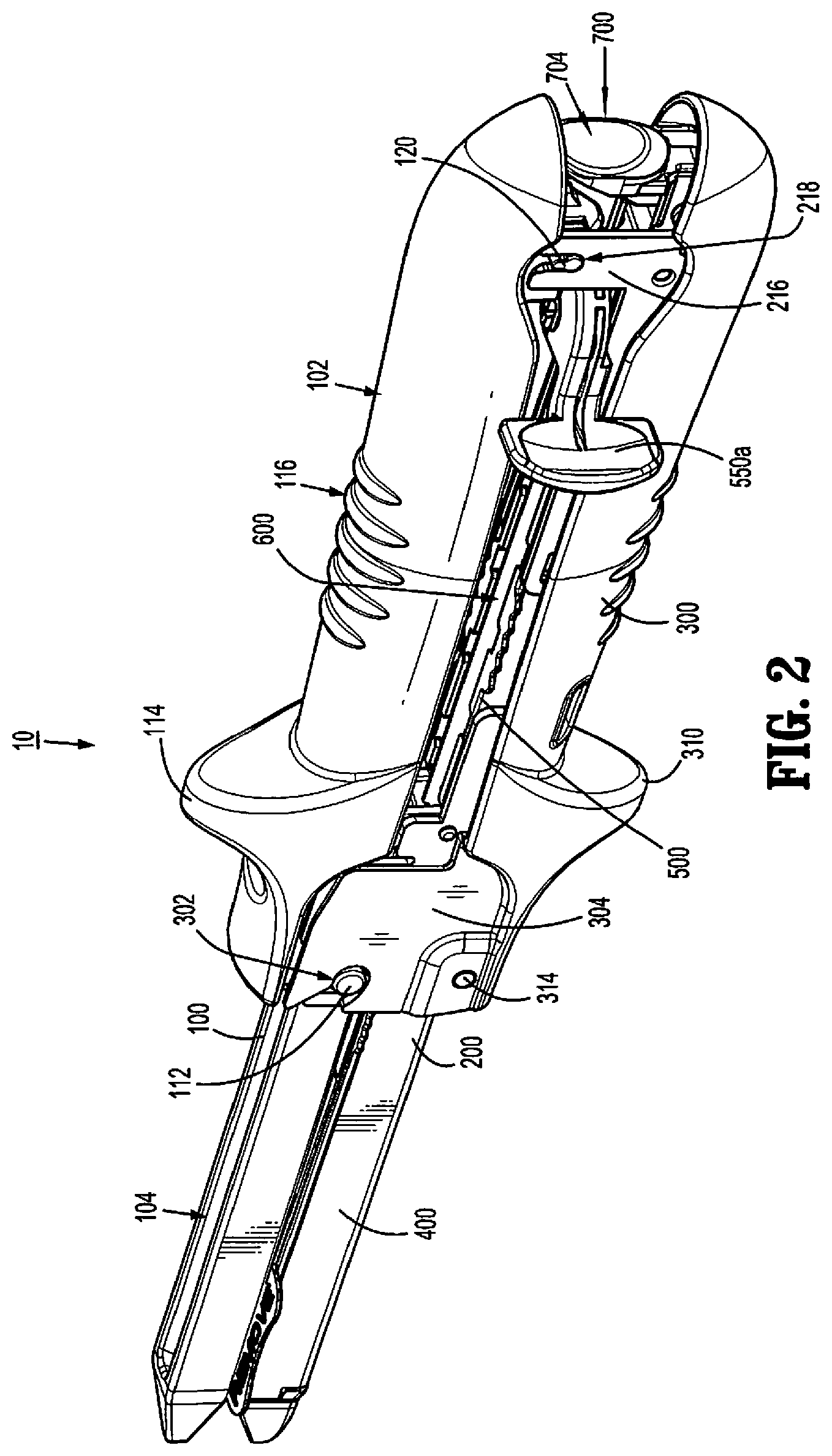
FIG. 2 is a side, perspective view from the proximal end of the surgical fastener applying apparatus shown in FIG. 1 in the clamped position;
FIG. 2A is a side, perspective view of the surgical fastener applying apparatus shown in FIG. 1 in the open position;
FIG. 2B is an enlarged view of the indicated area of detail shown in FIG. 2A;
FIG. 2C is a side, perspective view of the disposable assembly of the surgical fastener applying apparatus shown in FIG. 1;
FIG. 2D is top, perspective view of the frame of the disposable assembly shown in FIG. 2C;
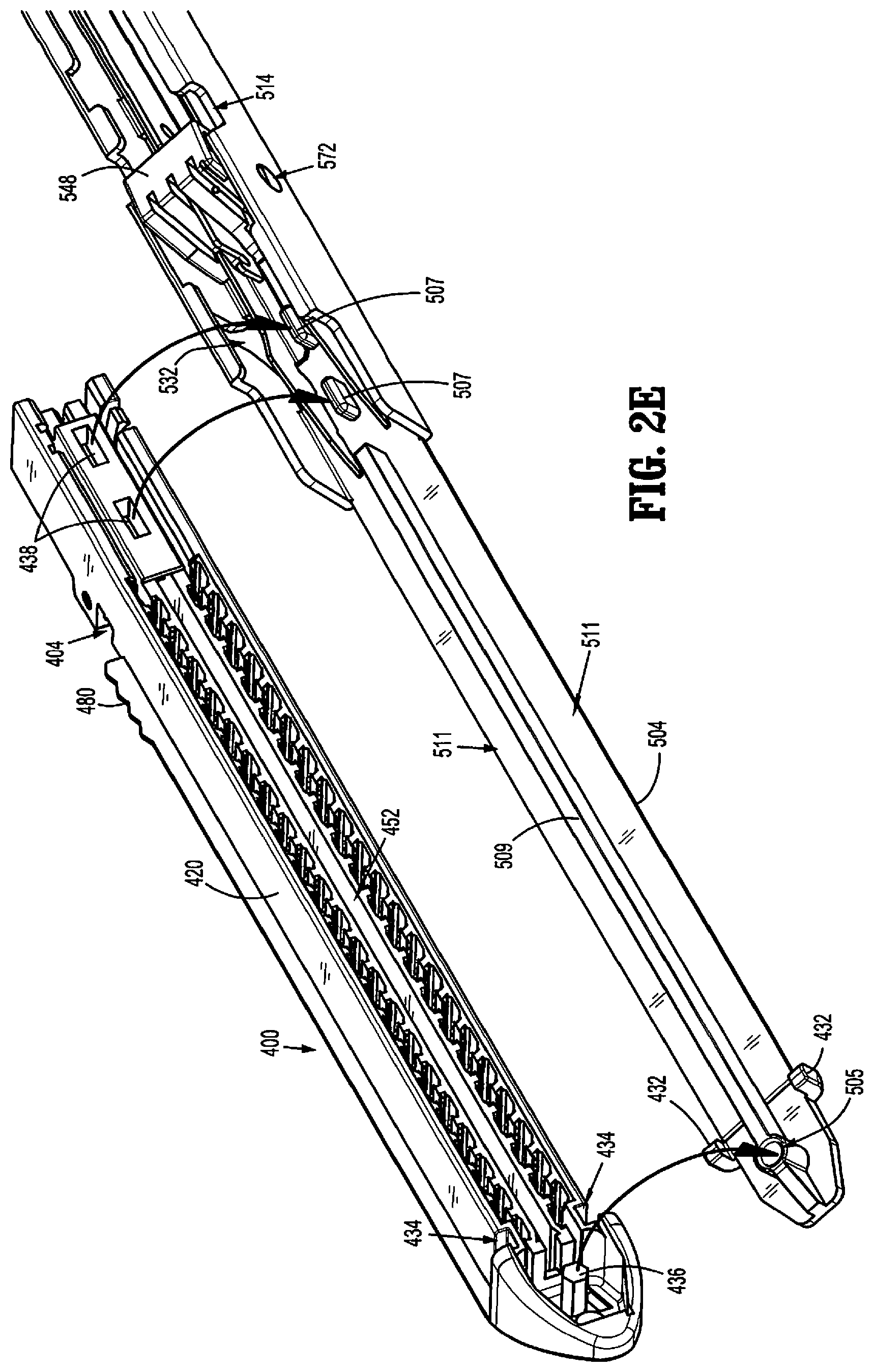
FIG. 2E is a top, perspective view of the distal portion of the disposable assembly shown in FIG. 2C with the SULU separated from the frame of the disposable assembly;
FIG. 2F is a side, perspective view of the cartridge receiving half-section of the surgical fastener applying apparatus shown in FIG. 1 with the handle in the open position.
FIG. 3 is a side, perspective view with parts separated of the surgical fastener applying apparatus shown in FIG. 1;
FIG. 3A is a side, cross-sectional view of the clamp lever of the fastener applying apparatus shown in FIG. 1;
FIG. 4 is a side, perspective view of the cartridge receiving half-section of the surgical fastener applying apparatus shown in FIG. 1 with the disposable assembly supported within the cartridge receiving half-section;
FIG. 5 is an enlarged view of the indicated area of detail shown in FIG. 4;
FIG. 6 is a perspective view from above of the cartridge receiving half-section of the surgical fastener applying apparatus with the disposable assembly supported therein;
FIG. 7 is an enlarged view of the indicated area of detail shown in FIG. 6;
FIG. 8 is a front end, perspective view from above of the disposable assembly of the surgical fastener applying apparatus shown in FIG. 3 with the SULU removed;
FIG. 9 is an enlarged view of the indicated area of detail shown in FIG. 8;
FIG. 9A is a top, perspective view of the channel member with the firing unit of the disposable assembly mounted therein;
FIG. 9B is an enlarged view of the indicated area of detail shown in FIG. 9A;
FIG. 9C is a top, perspective view of a central portion of the channel member;
FIG. 10 is a rear end, perspective view from above of the disposable assembly absent the SULU shown in FIG. 8;
FIG. 11 is an enlarged view of the indicated area of detail shown in FIG. 10;
FIG. 12 is a side, perspective view of the disposable assembly absent the SULU shown in FIG. 10 with parts separated;
FIG. 12a is a bottom, perspective view of the cam bar of the firing unit of the disposable assembly shown in FIG. 12;
FIG. 12b is a bottom, perspective view of the firing lever of the firing unit of the disposable assembly shown in FIG. 12;
FIG. 13 is a side, perspective view of the SULU of the surgical fastener applying apparatus shown in FIG. 1;
FIG. 14 is an enlarged view of the indicated area of detail shown in FIG. 13;
FIG. 15 is a front, perspective view of the SULU shown in FIG. 13;
FIG. 16 is an enlarged view of the indicated area of detail shown in FIG. 15;
FIG. 17 is a side, perspective view with parts separated of the disposable assembly shown in FIG. 2C (absent the firing unit);
FIG. 18 is a side, cross-sectional view of the surgical fastener applying apparatus shown in FIG. 1 in the open position;
FIG. 19 is an enlarged view of the indicated area of detail shown in FIG. 18;
FIG. 20 is an enlarged view of the indicated area of detail shown in FIG. 18;
FIG. 21 is a perspective view of the proximal end of the surgical fastener applying apparatus shown in FIG. 18 in the open position;
FIG. 22 is an enlarged view of the indicated area of detail shown in FIG. 18;
FIG. 23 is a perspective view from below of the proximal end of the clamping lever of the surgical fastener applying apparatus shown in FIG. 1;
FIG. 24 is a side, perspective view of the surgical fastener applying apparatus shown in FIG. 1 in the clamped position;
FIG. 25 is a side, cross-sectional view of the surgical fastener applying apparatus shown in FIG. 24 in the clamped position;
FIG. 26 is an enlarged view of the indicated area of detail shown in FIG. 25;
FIG. 27 is an enlarged view of the indicated area of detail shown in FIG. 25;
FIG. 28 is a cross-sectional view taken along section lines 28-28 of FIG. 26;
FIG. 29 is a top view of the surgical fastener applying apparatus shown in FIG. 1 as the firing unit is moved through an actuating stroke to eject fasteners from the SULU of the fastener applying apparatus;
FIG. 30 is a side, cross-sectional view of the surgical fastener applying apparatus shown in FIG. 29 with the firing unit in the actuated position;
FIG. 31 is an enlarged view of the indicated area of detail shown in FIG. 30;
FIG. 32 is an enlarged view of the indicated area of detail shown in FIG. 30;
FIG. 33 is a side, cross-sectional view of the surgical fastener applying apparatus shown in FIG. 1 after the apparatus has been fired and moved to the open position; and
FIG. 34 is an enlarged view of the indicated area of detail shown in FIG. 33.
DETAILED DESCRIPTION
Embodiments of the presently disclosed surgical fastener applying apparatus in accordance with the present disclosure will now be described in detail with reference to FIGS. 1-34, wherein like reference numerals identify similar or identical structural elements. As used herein, as is traditional, the term "proximal" refers to the end of the apparatus which is closer to the user and the term distal refers to the end of the apparatus which is further away from the user.
Turning to FIGS. 1-3, one embodiment of the presently disclosed surgical fastener applying apparatus is shown generally identified as surgical stapler 10. Surgical stapler 10 includes an anvil half-section 100, a cartridge-receiving half-section 200, a clamping lever 300, and a disposable assembly 600 including a single use loading unit 400 (hereinafter "SULU") and a firing unit 500. Each of these components or assemblies will be described in greater detail hereinbelow.
Anvil half-section 100, cartridge-receiving half-section 200 and clamping lever 300 may be configured as reusable components and, as such, are constructed from biocompatible materials suitable for sterilization and repeated use, e.g., stainless steel. SULU 400 and firing unit 500, on the other hand, are integrated with one another to form disposable assembly 600. The integration of SULU 400 and firing unit 500 into a single disposable assembly 600 facilitates disengagement and separation of the disposable components of surgical stapler 10 from the reusable components of surgical stapler 10 as a single unit, thus facilitating disposal of the disposable components and preparation of the reusable components for sterilization. Such a configuration also facilitates engagement of a new disposable assembly 600 with the sterilized reusable components in preparation for subsequent use. The integration of SULU 400 and firing unit 500 also facilitates removal of the used disposable assembly and replacement with a fresh disposable assembly for subsequent firings in a single surgical procedure. Disposable assembly 600, e.g., SULU 400 and firing unit 500, may be constructed from any suitable biocompatible materials, e.g., plastics, metals, or combinations thereof. Further, surgical stapler 10 may be configured to receive or accommodate disposable assemblies of various different configurations, e.g., disposable assemblies including SULU's and firing assemblies for firing staples of different staple line lengths (e.g., 60 mm, 80 mm and 100 mm).
As will be described in greater detail below, anvil half-section 100 and cartridge-receiving half-section 200 are releasably pivotably engagable with one another, while clamping lever 300 is pivotably coupled to cartridge-receiving half-section 200 about a central portion 202 thereof. Clamping lever 300 is pivotable relative to cartridge-receiving half-section 200 between a spaced-apart position (FIG. 2A) and an approximated position (FIGS. 1-2) for moving cartridge-receiving half-section 200 and anvil half-section 100 relative to one another between an open, or un-clamped position (FIG. 2A, FIG. 33) and a closed, or clamped position (FIGS. 1-2) for clamping tissue therebetween. With surgical stapler 10 in the clamped position, firing unit 500 may be operated to sequentially fire and form a plurality of surgical staples 402 (FIG. 17) about tissue clamped between anvil half-section 100 and cartridge-receiving half-section 200 and for advancing a knife 440 (FIG. 17) to divide tissue between the stapled portions thereof.
Continuing with reference to FIGS. 1-3, anvil half-section 100 includes a proximal handle portion 102 and a distal anvil portion 104. Anvil portion 104 includes staple deforming portion 106 which includes a plurality of staple deforming recesses (not shown) defined therein. Staple deforming portion 106 is disposed in opposing relation relative to SULU 400 when disposable assembly 600 is engaged within channel member 206 of cartridge-receiving half-section 200. Further, staple deforming portion 106 includes a central longitudinal slot (not shown) for receiving knife 440 of SULU 400 (FIG. 17) as the knife 440 is advanced through SULU 400 to divide the stapled tissue. Staple deforming portion 106 can be formed integrally with anvil half-section 100 or, alternatively, may be secured to anvil half-section 100 by any suitable fastening process, e.g., welding.
A pair of locating fingers 108 (FIG. 2A) disposed on a central portion of anvil half-section 100 and positioned adjacent the proximal end of the staple deforming portion 106 of anvil portion 104 extend from anvil half-section 100 towards SULU 400 of disposable assembly 600. Upon approximation of anvil half-section 100 and cartridge-receiving half-section 200, locating fingers 108 are at least partially received within grooves 404 (FIG. 2E) defined within SULU 400 to properly align SULU 400 with staple deforming portion 106 as surgical stapler 10 is moved to the clamped position. Anvil half-section 100 further includes a pair of transversely-spaced extensions 110 (FIG. 2A) positioned proximally of fingers 108 which extend downwardly towards disposable assembly 600. Extensions 110 each define an angled distal surface and are configured for engagement within notches 514 (FIG. 2E) of stationary housing 502 of disposable assembly 600 upon movement of surgical stapler 10 to the clamped position such that the angled distal surfaces of extensions 110 and notches 514 mate with one another. The angled surfaces of extensions 110 are each also configured to contact an upper surface of guide block 548 (FIG. 2E) as extensions 110 are translated towards notches 514, i.e., as surgical stapler 10 is moved towards the clamped position, such that, as will be described in greater detail below, guide block 548 is pivoted from a first, locked position (FIG. 19) to a second, unlocked position (FIG. 26).
Referring to FIGS. 2A and 3, a central portion of anvil half-section 100 includes a pair of cylindrical lateral support members 112. During assembly of anvil half-section 100 and cartridge-receiving half-section 200, lateral support members 112 are supported in U-shaped recesses 214 defined in a central portion 202 of cartridge-receiving half-section 200 (FIG. 3). A distal wall 204 of central portion 202 defines a tissue stop (FIG. 3). Lateral support members 112 are also positioned to be received in cutouts 302 formed on spaced flange portions 304 of clamping lever 300 when the clamping lever 300 is moved to the clamped position (FIG. 2). Proximal handle portion 102 is ergonomically formed and includes a thumb-engaging abutment 114 and a gripping portion 116. A proximal end of handle portion 102 includes a downwardly extending finger 118 which includes a pair of opposed teardrop shaped protrusions 120 (FIG. 3) which will be discussed in further detail below. Alternatively, protrusions 120 may assume a variety of other configurations.
Referring to FIGS. 3-7, cartridge-receiving half-section 200 includes an elongated channel member 206 having a substantially U-shaped channel 208 defined therein that is configured to releasably receive disposable assembly 600. More specifically, U-shaped channel 208 includes a distal portion 210 dimensioned to releasably receive distal extension 504 of stationary housing 502 of disposable assembly 600 which supports SULU 400, and a proximal portion 212 dimensioned to releasably receive the proximal portion of stationary housing 502 of disposable assembly 600 which supports firing unit 500. Disposable assembly 600 and the components thereof, i.e., SULU 400 and firing unit 500, will be described in greater detail hereinbelow.
As mentioned above, cartridge-receiving half-section 200 includes spaced centrally disposed U-shaped recesses 214 positioned to support lateral support members 112 of anvil half-section 100. The proximal end of cartridge-receiving half-section 200 includes a pair of vertical support members 216. Each vertical support member 216 includes an elongated vertical slot 218 having a rounded bottom surface. Vertical slots 218 are dimensioned to receive protrusions 120 formed on finger 118 of anvil half-section 100 (FIG. 21) when the anvil half-section 100 is supported on the cartridge-receiving half-section 200 during assembly. By positioning protrusion 120 within the vertical slots 218, anvil half-section 100 can be pivoted in a scissor-like manner with respect to the cartridge-receiving half-section 200 between the open and closed positions. In one embodiment, protrusions 120 have a teardrop profile. Alternatively, other protrusion configurations are envisioned.
Cartridge-receiving half-section 200 further includes a pair of generally cylindrical protrusions 220 disposed at the proximal end thereof and extending inwardly into U-shaped channel 208. Protrusions 220 are configured to be received within arcuate slots 516 defined in stationary housing 502 of disposable assembly 600 to facilitate engagement of disposable assembly 600 within cartridge-receiving half-section 200. Cartridge-receiving half-section 200 also includes a pair of opposed cut-out sections 222 configured to receive outwardly-extending serrated surfaces 518 of stationary housing 502. Serrated surfaces 518 provide a grippable surface to facilitate removal and/or replacement of disposable assembly 600 from channel member 206 of cartridge-receiving half-section 200. A pair of opposed openings 224 defined through the sidewalls of channel member 206 are configured to engage flared tabs 520 of stationary housing 502 to releasably secure disposable assembly 600 within cartridge-receiving half-section 200.
Clamping lever 300, as best shown in FIGS. 3 and 3A, includes a handle portion 306 including a grip 308 and a thumb engaging abutment 310. As discussed above, a pair of spaced flange portions 304 are supported on the distal end of clamping lever 300. Each flange portion 304 defines a cutout 302 dimensioned to receive a respective lateral support member 112 of anvil half-section 100 when stapler 10 is moved towards the clamped position (FIG. 2B). The distal end of clamping lever 300 also defines a pair of openings 312 which are dimensioned to receive a pivot member 314, e.g. a pin. Pivot member 314 is dimensioned to extend through openings 226 in cartridge-receiving half-section 200 and openings 312 in clamp lever 300 to pivotally secure clamp lever 300 to cartridge-receiving half-section 200. A spring member 316 includes a folded-under, T-shaped proximal end 318 that is engaged within opposed slots 320 defined within opposed side walls of clamping lever 300 and may be secured therein in any suitable fashion, e.g., mechanical engagement, welding, adhesion, etc. The distal end 322 of spring member 200 is configured to abut an undersurface of cartridge-receiving half-section 200 to bias clamping lever 300 apart from cartridge-receiving half-section 200, i.e., to bias clamping lever 300 towards the spaced-apart, or un-clamped position. Clamping lever 300 further includes an engagement member, e.g., semi-cylindrical post 324, which, as will be described in greater detail below, is configured to engage latch portion 706 of locking member 700 of firing unit 500 when clamp lever 300 is moved to the clamped position (FIG. 27). Although a semi-cylindrical post 324 is illustrated, other engagement member configurations are also envisioned.
Turning now to FIGS. 2C-3 and 8-12, disposable assembly 600 includes SULU 400 and firing unit 500 integrated with one another to form a single component, i.e., disposable assembly 600. More specifically, disposable assembly 600 includes a stationary housing 502 configured to house the working components of firing unit 500, which will be described below, and a distal extension 504 that is configured to engage and retain SULU 400 thereon, thus forming an integrated disposable assembly 600. Distal extension 504 of disposable assembly 600 extends distally from stationary housing 502.
Stationary housing 502 includes a proximal end including opposed openings 506 (FIG. 2D) which receive pivot member 508 (FIG. 12). Pivot member 508 extends through openings 506 defined within each of the sidewalls of stationary housing 502 and through bore 702 defined transversely though locking member 700. Locking member 700 is pivotably coupled between sidewalls of stationary housing 502 adjacent the proximal end of firing unit 500 of disposable assembly 600. Pivot member 508 may include a bifurcated insertion end defining a pair of resilient locking tabs 510 (FIG. 12) such that, upon insertion of pivot member 508 through the first opening 506, bore 702, and out of the second opening 506, resilient locking tabs 510 bias outwardly to lock pivot member 508 in pivotable engagement therethrough.
Referring also to FIG. 12, locking member 700 includes a push-button 704 disposed on one side of pivot member 508 and a latch portion 706 including a hook member 708 disposed on the opposed side of pivot member 508. A biasing member 512 is positioned about pivot member 508 to urge latch portion 706 inwardly towards stationary housing 502 of disposable assembly 600, thus urging push-button 704 outwardly therefrom. Latch portion 706 extends downwardly beyond the proximal end of stationary housing 502 to a position below a bottom surface of channel member 206 (FIG. 20) such that hook member 708 of latch portion 706 is exposed. The exposed hook member 708 of locking member 700, facilitated by the bias of biasing member 512, is configured to engage semi-cylindrical post 324 (FIG. 3) of clamping lever 300 upon movement of clamping lever 300 to the clamped position, thereby locking clamping lever 300 in the clamped position. Push-button 704 is selectively depressible against the bias of spring 512 to disengage hook member 708 from post 324 to unlock clamping lever 300, this allowing clamping lever 300 to return under bias of spring 316 back to the open, or unclamped position.
Referring to FIGS. 2D and 8-12, the components and features of firing unit 500 are described. Firing unit 500 is supported within stationary housing 502 of disposable assembly 600 and includes a knife actuating bar 544, a cam bar 546, a guide block 548, a firing lever 550, a slide block 552, a pedal 554 and the pivotal locking member 700 (FIG. 12). As shown in FIG. 2D, stationary housing 502 includes a U-shaped frame 522 including a pair of sidewalls 524 and a bottom wall 526 which extends distally beyond sidewalls 524 to form distal extension 504. Sidewalls 524 each include a plurality of spaced-apart, inwardly-extending tabs 528 disposed along the free ends thereof and bottom wall 526 includes a plurality of spaced-apart slots 530 defined therethrough adjacent each of sidewalls 524, each of which is positioned to oppose one of the tabs 530. This slotted and tabbed configuration of frame 522 of stationary housing 502 provides increased flexibility and resiliency to stationary housing 502, thus facilitating insertion and removal of disposable assembly 600 from cartridge-receiving half-section 200 and engagement of disposable assembly 600 within cartridge-receiving half-section 200 (FIG. 9A), e.g., facilitating pinching, or squeezing of serrated surfaces 518 of stationary housing 502 to insert and/or remove stationary housing 502 from cartridge-receiving half-section 200. The distal-most tabs 528 of stationary housing 502 may also be configured to engage the proximal end of SULU 400 to facilitate the engagement of SULU 400 on distal extension 504. As mentioned above, stationary housing 502 is configured for releasable engagement within U-shaped channel 208 of cartridge-receiving half-section 200 via the engagement of flared tabs 520 of stationary housing 502 within opposed openings 224 of cartridge-receiving half-section 200 (FIG. 4) and protrusions 220 of cartridge-receiving half-section 200 within arcuate slots 516 of stationary housing 502 (FIG. 3). More specifically, flared tabs 520 are configured to bias into engagement within opposed openings 224 upon insertion of stationary housing 502 into cartridge-receiving half-section 200. Sidewalls 524 may be squeezed inwardly to facilitate such insertion of stationary housing 502 within cartridge-receiving half-section 200. In order to remove stationary housing 502 from cartridge-receiving half-section 200, sidewalls 524 of stationary housing 502 may be squeezed, or pinched toward one another (e.g., via grasping and squeezing serrated surfaces 518 toward one another) to facilitate retraction of flared tabs 520 from openings 224, thus permitting withdrawal of stationary housing 502 from cartridge-receiving half-section 200. To this end, stationary housing 502 may be formed from a plastic, or other suitable material capable of resiliently flexing to facilitate engagement and disengagement of stationary housing 502 within cartridge-receiving half-section 200, One (or both) of the sidewalls 524 of stationary housing 502 includes a bottleneck opening 532 defined therethrough that is configured to receive resilient finger 230 (FIGS. 9B-9C) of cartridge-receiving half-section 200, to ensure engagement between disposable assembly 600 and cartridge-receiving half-section 200.
With reference to FIGS. 1-3 and 8-12, the distal ends of sidewalls 524 each define a notch 514 having an angled distal surface. Notches 514 are configured to receive extensions 110 of anvil half-section 100, as mentioned above, to ensure proper alignment between SULU 400 and staple deforming portion 106 when surgical stapler 10 is moved to the clamped position. Each sidewall 524 also includes an outwardly extending serrated surface 518 that is positionable within the opposed cut-out sections 222 of cartridge-receiving half-section 200 to facilitate gripping and squeezing of the disposable assembly 600 to allow for removal and/or replacement of disposable assembly 600 from channel member 206 of cartridge-receiving half-section 200 and to ensure a substantially flush-fit of disposable assembly 600 within cartridge-receiving half-section 200, i.e., such that serrated surfaces 518 are substantially flush with the free ends of channel member 206 of cartridge-receiving half-section 200.
Guide block 548 includes a body defining three longitudinal slots 570a-c and a pair of outwardly extending protrusions 572. In one embodiment, each protrusion 572 is substantially cylindrical and includes a tapered portion (FIG. 9). Alternatively, other protrusion configurations are envisioned. Protrusions 572 are dimensioned to be received in openings 574 (FIG. 12) formed in sidewalls 524 of stationary housing 502 to axially fix guide block 548 within the distal end of stationary housing 502. Protrusions 572 allow for a degree of pivotal movement of guide block 548 within U-shaped frame 522. As will be discussed in further detail below, guide block 548 is pivotal from the first position (FIG. 19) in locking engagement with notches 549 and 551 of knife actuating bar 544 to the second position (FIG. 26) disengaged from notches 549 and 551 of knife actuating bar 544 in response to movement of stapler 10 to the clamped position. More specifically, as anvil half-section 100 is approximated relative to cartridge-receiving half-section 200 to achieve the clamped position, extensions 110 of anvil half-section 100 urge guide block 548 to pivot from the first position (FIG. 19) to the second position (FIG. 26) to disengage the lockout mechanism. A torsion spring 556 is disposed about one or both of the protrusions 572 to urge guide block 548 into locking engagement with notches 549 and 551, i.e., to bias guide block 548 into the first, locked position (FIG. 19). Each of slots 570a and 570c is dimensioned to slidably receive a respective sidewall 547 of cam bar 546. Similarly, slot 570b is dimensioned to slidably receive knife actuating bar 544.
Referring to FIGS. 8-17, slide block 552 includes a hub 580 which includes a resilient finger 580a configured to be snap-fit into a pivot hole 582 formed in firing lever 550. Firing lever 550 is pivotal about hub 580 when the slide block 552 is in a retracted position to facilitate actuation of the firing unit 500 from either side of stapler 10. Pedal 554 is reciprocally received within a hole 584 formed in slide block 552. Pedal 554 includes a split body portion 554a which is configured to straddle a proximal end 558 of knife actuating bar 544. In one embodiment, split body portion 554a includes an angled distal surface 586. A pin 588 extends upwardly from pedal 554 through hole 584 in slide block 552. A biasing member 590 is positioned between split body portion 554a and slide block 552, about pin 588 to urge pedal 554 downwardly away from slide block 552 to an extended position. In the retracted position of slide block 552, pedal 554 is received in a cutout 555 formed in a bottom wall of channel member 206 (FIG. 20).
Firing lever 550, as best shown in FIGS. 2C, 3 and 20-24, includes first and second finger engagement members 550a and 550b, either one of which can be selectively engaged to move the firing lever 550 through a firing stroke from either side of stapler 10. An arcuate recess 594 (FIG. 12B) is formed in a bottom surface of firing lever 550 which slidably receives pin 588 of pedal 554 to define the range of rotation through which firing lever 550 can pivot about hub 580 of slide block 552. As used herein, a firing stroke is defined as movement of firing lever 550 from a fully retracted position (FIG. 25) to a fully advanced position (FIG. 30). A stop recess 594a is formed at each end of arcuate recess 594. Stop recesses 594a are configured and dimensioned to receive the end of pin 588 of pedal 554 to prevent pivotal movement of firing lever 550 about hub 580 during a firing stroke of surgical stapler 10. More specifically, when the firing unit 500 is actuated to advance slide block 552 distally within stationary housing 502, angled distal surface 586 of pedal 554 engages channel member 206 and is cammed out of cutout 555 (FIG. 27) to urge pin 588 upwardly into a stop recess 594a to prevent pivotal movement of firing lever 550 during movement of firing lever 550 through a firing stroke. As is evident, pin 588 must be positioned beneath a stop recess 594a to allow pedal 554 to lift upwardly from cutout 555 to allow firing lever 550 to be moved through the firing stroke. Thus, firing lever 550 must be pivoted to one side or the other of firing unit 500 before the firing lever 550 can be moved through a firing stroke.
Knife actuating bar 544 includes a proximal end having a stepped portion 596 which includes a proximal first step 597a having a first height and a second step 597b having a second height which is greater than the first height (FIG. 12). A distal end of actuating bar 544 includes an upturned hook portion 598 and upper and lower notches 549 and 551. A finger 599 projects upwardly from knife actuating bar 544 between first and second steps 597a and 597b. As shown in FIG. 27, finger 599 is slidably received within a recess 553 formed in an underside of slide block 352. When slide block 552 is advanced distally within stationary housing 502, finger 599 moves within recess 553 such that slide block 552 moves in relation to knife actuating bar 544 until finger 599 engages a wall 553a defining the proximal end of recess 553. When finger 599 engages wall 553a, further distal movement of slide block 552 will also effect distal movement of knife actuating bar 544. As will be evident below, this arrangement allows for staples to be ejected from SULU 400 prior to cutting of tissue.
Referring to FIGS. 12 and 12A, cam bar 546 includes a pair of sidewalls 547 and a base wall 559. The proximal end 547a of each sidewall 547 includes a raised wall portion 547b. Each raised wall portion 547b is configured to be fixedly received in a slot (not shown) formed in an underside of slide block 552 to fixedly secure the proximal end of cam bar 546 to slide block 552. Alternately, slide block 552 may be molded about the proximal end of cam bar 546. The distal end 547c of each sidewall 547 includes an angled camming surface 547d. Base wall 559 defines a distally extending elongated slot 559a (FIG. 12A) which extends from the distal end of cam bar 546 along a substantial length of the cam bar 546 and a proximally extending longitudinal slot 559b. Slot 559b is positioned to facilitate the passage of pedal 554 through cutout 555 of channel member 206 when slide block 552 is in the retracted position (see FIG. 27).
Sidewalls 547 of cam bar 546 are slidably positioned in slots 570a and 570c of guide block 548 and knife actuating bar 544 is slidably positioned in longitudinal slot 570b of guide block 548. When firing unit 500 is supported in channel member 206 and firing lever 550 is pivoted to one side of stationary housing 502 and pushed distally, slide block 552 is moved distally within stationary housing 502. As slide block 552 begins to move distally, tapered surface 586 of pedal 554 engages a proximal edge of channel member 206 defining cutout 555 to urge pedal 554 upwardly out of cutout 555, through slot 559b of cam bar 546, and onto an inner surface of stationary housing 502 of disposable assembly 600 (FIG. 27). As this occurs, pin 588 of pedal 554 moves into a stop recess 594a to prevent further pivotal movement of firing lever 550. If firing lever 550 is not pivoted to a position in which pin 588 is positioned beneath a stop recess 594a, pedal 554 will be prevented from moving upwardly out of cutout 555 and firing lever 550 will be prevented from moving through a firing stroke. As firing lever 550 is moved distally, finger 599 moves within recess 553 such that knife actuating bar 544 remains stationary as cam bar 546 is advanced distally. When finger 599 engages proximal wall 553a defining recess 553, knife actuating bar 544 is moved distally with slide block 552 and cam bar 546. As will be discussed below, when cam bar 546 and knife actuating bar 544 are moved distally within stationary housing 502 of disposable assembly 600 and channel member 206, angled camming surfaces 547d of cam bar 546 are moved through SULU 400 to eject staples 402 from SULU 400. Simultaneously, although with a preset delay equal to the length of recess 553 (FIG. 32), knife actuating bar 544 drives a knife blade 540 through SULU 400 to dissect tissue.
Distal extension 504 of stationary housing 502, as mentioned above, is configured to engage and retain SULU 400 thereon to form the integrated disposable assembly 600. As best shown in FIGS. 2C-2E, distal extension 504 engages SULU 400 to enclose the underside of cartridge body 420 of SULU 400, e.g., distal extension 504 forms the bottom cover of cartridge body 420 of SULU 400. More specifically, a pair of cantilever arms 432 extending from opposed sides of distal extension 504 engage cutouts 434 formed at the distal end of cartridge body 420 of SULU 400; a central lumen 505 defined towards the distal end of distal extension 504 receives a post 436 extending from the distal tip portion of cartridge body 420; proximal protrusions 507 extending from the proximal end of distal extension 504 are received within corresponding slots 438 defined within the proximal portion of SULU 400; and the distal-most tabs 528 of sidewalls 524 of stationary housing 502 are engaged about the proximal end of SULU 400 to engage SULU 400 and distal extension 504 of firing unit 500 to one another. Thus, SULU 400 is fixedly secured to distal extension 504 via a snap-fit engagement and a male-female connection at both the distal end of SULU 400 and at the proximal end of SULU 400. That is, the engagement, e.g., snap-fit engagement, of cantilever arms 432 within cutouts 434 retains post 436 within central lumen 505 at the distal end of SULU 400, while the engagement, e.g., snap-fit engagement, of distal-most tabs 528 of sidewalls 524 about the proximal end of SULU 400 retains proximal protrusions 507 within slots 438 at the proximal end of SULU 400. Further, these engagements may be further facilitated by friction fitting, e.g., post 436 may be frictionally retained within lumen 505 and/or proximal protrusions 507 may be frictionally retained within slots 438 and/or in any other suitable fashion, e.g., gluing or adhesion, ultrasonic or other suitable welding process, heat staking, etc. Distal extension 504 of firing unit 500 further includes a longitudinal ridge 509 formed on an upper surface thereof that is received within cartridge body 420 of SULU 400, the importance of which will be described below.
Referring to FIGS. 13-17, SULU 400 is described. SULU 400 includes cartridge body 420, a plurality of staple pushers 422 (only one is shown), a knife 440 having an angled sharpened leading edge or blade 440a, a plurality of staples 402 (only one is shown), and a pivotally mounted safety lockout 428. Body 420 has a plurality of rows of staple retaining slots 430, e.g., four, six, etc. and a linear slotted knife track 452 centrally disposed in body 420. Knife 440 includes a downturned hook portion 440b which is positioned to engage upturned hook portion 598 (FIG. 12) of knife actuating bar 544 of firing unit 500. In the illustrated embodiment, body 420 includes two staggered rows of slots 430 formed on either side of linear slotted knife track 452. The staggered rows of slots 430 extend beyond the distal end of knife track 452 to facilitate staple formation beyond the distal end of the stroke of the knife blade 440a, although other configurations are contemplated.
Staple pushers 422 may be configured to extend into one or more slots 430. In one embodiment, a single pusher is associated with each slot 430. Alternatively, as illustrated in FIG. 17, each pusher 422 can be configured to extend into two adjacent slots 430 and is positioned beneath respective staples 402 which are retained in slots 430. Further, each pusher 422 includes a lower cam surface 422a which is positioned to engage one of cam surfaces 547d (FIGS. 12, 12A) on the distal end of cam bar 546 such that movement of cam bar 546 through SULU 400 sequentially lifts each respective pusher 422 within its respective slot or slots 430 to eject staples from slots 430.
Longitudinal ridge 509 of distal extension 504 (FIG. 2E), as mentioned above, is received within cartridge body 420 of SULU 400. Longitudinal ridge 509 provides a bearing surface for a knife supporting member 496 (FIG. 17), which is secured to a bottom edge of knife 440. Knife 440 may be secured to supporting member 496 via pins, welding or other known fastening techniques. During a firing stroke, as will be described below, knife 440 is guided along knife track 452 as the firing lever 550 is advanced through channel member 206. A pair of slots 511 (FIG. 2D) are defined between the sides of ridge 509 and an outer wall of cartridge body 420. Longitudinal ridge 509 is positioned within body 420 and dimensioned to be slidably received within slot 559a (FIG. 12A) of cam bar 446 such that cam bar 446 is slidably movable through cartridge body 420 about longitudinal ridge 509 to eject staples 402 from SULU 400.
A proximal end of SULU 400 includes opposed, outwardly extending serrated surfaces 480 (FIG. 7) to facilitate gripping of the proximal end of SULU 400 to allow for removal and/or replacement of disposable assembly 600 from channel member 206 of cartridge-receiving half-section 200. Thus, removal and/or replacement of disposable assembly 600 may be effectuated by grasping either or both of serrated surfaces 480 of SULU 400 and serrated surfaces 518 of stationary housing 502.
Referring to FIGS. 13-17, safety lockout 428 is pivotally disposed on an upper proximal end of body 420 and is pivotal about a pivot member 450 from a locked orientation (FIG. 26) to unlocked orientation (FIG. 34). Pivot member 450 is received in openings 454 in body 420. A biasing member, e.g., spring 451, is positioned between knife supporting member 496 and safety lockout 428 to urge safety lockout 428 towards the unlocked orientation. Safety lockout 428 includes a proximal hook 456 which is positioned to receive an engagement member 458 formed on the knife 440 to retain the safety lockout 428 in the locked orientation when the knife 440 is in the retracted position (FIG. 19). When the knife 440 is moved towards the advanced position during a firing stroke, engagement member 458 is moved away from proximal hook 456 to allow safety lockout 428 to pivot towards the unlocked position in response to the urging of spring 451. It is noted that safety lockout 428 is prevented from pivoting to the unlocked position when the anvil half-section 100 and cartridge-receiving half-section 200 are in the clamped position because the top surface 428a of safety lockout 428 engages an inner surface of anvil half-section 100 to prevent pivoting of safety lockout 428. Safety lockout 428 defines a slot 460 dimensioned to slidably receive the knife 440. In the retracted position of the knife 440, the leading edge 440a of knife 440 is confined within slot 460 of safety lockout 428 to prevent accidental engagement and injury to medical personnel with leading edge 440a of knife 440.
The assembly and operation of surgical stapler 10 is now described with reference to FIGS. 1-34. Initially, disposable assembly 600 is engaged within cartridge-receiving half-section 200. In order to engage disposable assembly 600 within cartridge-receiving half-section 200, disposable assembly 600, which includes SULU 400 and firing unit 500, is generally aligned above cartridge-receiving half-section 200 and is inserted into U-shaped channel 208 of channel member 206. More specifically, disposable assembly 600 is aligned with cartridge-receiving half-section 200 such that, upon translation of disposable assembly 600 into U-shaped channel 208 of channel member 206, protrusions 220 are engaged within arcuate slots 516, flared tabs 520 are engaged within opposed openings 224, and resilient finger 230 is engaged within bottleneck opening 532, thus releasably engaging disposable assembly 600 within cartridge-receiving half-section 200. Installation of disposable assembly 600 may be facilitated, as discussed above, by grasping serrated surfaces 518 of stationary housing 502 (and, in particular, by grasping and squeezing serrated surfaces 518 inwardly) and/or by grasping serrated surfaces 480 of SULU 400.
Once disposable assembly 600 is loaded into channel member 206, anvil half-section 100 can be assembled to cartridge-receiving half-section 200 as shown in FIG. 2A. To attach anvil half-section 100 to cartridge-receiving half-section 200, protrusions 120 of fingers 118 are positioned in vertical slots 218 of vertical support member 216 of cartridge-receiving half-section 200. Thereafter, anvil half-section 100 is rotated towards cartridge-receiving half-section 200 to position lateral supports members 112 in U-shaped recesses 214. In this position, surgical stapler 10 is ready for use.
In use, with surgical stapler 10 in the open, or unclamped position, surgical stapler 10 is manipulated into position such that tissue to be stapled and divided is disposed between anvil half-section 100 and cartridge-receiving half-section 200. Thereafter, surgical stapler 10 may be moved to the clamped position to clamp tissue between SULU 400 and staple deforming portion 106 of anvil half section 100. In order to position surgical stapler 10 in the clamped position, clamping lever 300 is rotated in a counter-clockwise direction from the position shown in FIG. 2A after the anvil half section and cartridge receiving half section 200 are attached. As clamping lever 300 is rotated, against the bias of spring member 316 (FIG. 3), lateral support members 112 are received in cutouts 302 (FIG. 2) of flange portions 304 of clamp lever 300 and are cammed towards cartridge-receiving half-section 200. In the clamped position, as shown in FIG. 1, staple deforming portion 106 is positioned in close approximation with the top surface of SULU 400.
As shown in FIG. 27, as clamping lever 300 is moved towards the clamped position, an angled face 707 (FIG. 20) of latch portion 706 engages post 324. This engagement causes locking member 700 to pivot about pivot member 508 such that hook member 708 of latch portion 706 slides about the other surface of post 324 and, ultimately, snaps into engagement with post 324. To release latch portion 706 from post 324, i.e., to release clamping lever 300 from the clamped position, push-button 704 of locking member 700 is depressed to pivot latch portion 706 out of engagement with post 324. When this occurs, spring member 316 urges clamping lever 300 back to the unclamped position.
Referring to FIGS. 3, 12, 19 and 26, as discussed above, guide block 548 is pivotally supported in stationary housing 502 of firing unit 500. As surgical stapler 10 is moved to the clamped position, extensions 110 of anvil half-section 100 are approximated relative to disposable assembly 600 such that extensions 110 eventually contact the upper surface of guide block 548 and urge guide block 548 to pivot in a generally counter-clockwise direction (from the position shown in FIG. 19 to the position shown in FIG. 26). As guide block 548 is pivoted from the locked position to the unlocked position, locking surfaces 545, which are initially received in notches 549 and 551 of knife actuating bar 544 when the stapler 10 is in an unclamped position, are rotated out of notches 549, 551 to unlock knife actuating bar 544 (FIG. 26). This configuration prevents movement of the knife actuating bar 544 in relation to guide block 548 prior to clamping, thus ensuring that the knife actuating bar 544 and knife 440 remain properly positioned for operational engagement prior to use.
Referring to FIGS. 24-28, when stapler 10 is in the clamped, unfired position, slide block 552 of firing unit 500 is in the retracted position at the proximal end of channel member 206 and stationary housing 502 (see FIG. 27). In this position, pedal 554 is positioned in cutout 555 of channel member 206 and pin 588 of pedal 554 is positioned in arcuate recess 594 of firing lever 550 beneath stop recesses 594a. As such, firing lever 550 can be pivoted to facilitate actuation of stapler 10 from either side of the stapler 10. In addition, in this position of slide block 552, finger 599 of knife actuating bar 544 is positioned adjacent distal wall 553b of recess 553 of slide block 552. Latch portion 706 of locking member 700 is also engaged with post 324 to retain clamping lever 300 in the clamped position.
Referring to FIG. 26, when slide block 552 is in the retracted position, knife 440 and cam surfaces 547d of cam bar 546 are positioned in the proximal end of SULU 400 and, proximal hook 456 of safety lockout 428 is positioned in engagement with engagement member 458 of knife 440 to retain safety lockout 428 in the locked orientation. In addition, downturned hook portion 440b of knife 440 is engaged with upturned hook portion 598 of knife actuating bar 544 to connect firing unit 500 to knife 440 of SULU 400.
Referring to FIGS. 29-32, when the firing lever 550 is advanced distally in the direction indicated by arrow "A" in FIG. 29, slide block 552 is moved distally within stationary housing 502 of firing unit 500 to effect corresponding movement of cam bar 546 and delayed movement of knife actuating bar 544. As discussed above, the delayed movement of the knife actuating bar 544 is equal to the length of recess 553 of slide block 552 and results from movement of finger 599 of knife actuating bar 544 within recess 553 of slide block 552. Movement of knife actuating bar 544 with slide block 552 begins when finger 599 abuts the proximal wall 553a of recess 553. As cam bar 546 is moved distally through stationary housing 502 of firing unit 500, cam surfaces 547d on sidewalls 547 of cam bar 546 are advanced through SULU 400 to sequentially engage pushers 422 to eject staples 402 from slots 430 of body 420. Concurrently, since the distal end of knife actuating bar 544 is engaged with knife 440, knife 440, after the preset delay, is advanced through SULU 400 to incise tissue between the staple lines.
As shown in phantom in FIG. 32, when slide block 552 moves distally within stationary housing 502, pedal 554 rides up over channel member 206 and moves along inner surface of stationary housing 502 disposable assembly 600. When this occurs, pin 588 of pedal 554 moves into a stop recess 594a to prevent further pivotal movement of firing lever 550.
Referring to FIGS. 31 and 32, when knife 440 is moved distally within SULU 400, engagement member 458 of knife 440 is disengaged from proximal hook 456 of safety lockout 428.
Referring to FIGS. 33 and 34, when the firing lever 550 is returned to its proximal-most position to retract cam bar 546 and knife 440, and the locking member 700 is depressed to disengage latch portion 706 from post 324, spring 316 urges clamping lever 300 to its unclamped position to allow stapler 10 to move to the open position. In the open position, anvil half-section 100 is spaced from cartridge-receiving half-section 200 and spring 451 (FIG. 17) pivots safety lockout 428 in the direction indicated by arrow "B" in FIG. 34 about pivot member 250 to its unlocked position such that safety lockout 428 projects upwardly from SULU 400. In the unlocked position, safety lockout 428 prevents movement of the stapler 10 back to the clamped position. In order to reuse stapler 10, used SULU 400 must be replaced with a new SULU 400 by replacing the used disposable assembly 600 with a new disposable assembly 600.
During a surgical procedure, disposable assembly 600 (including SULU 400 and firing assembly 500) can be replaced multiple times to facilitate multiple uses of stapler 10 on a single patient. Each disposable assembly 600 is provided with a fresh knife. Further, each disposable assembly 600 is also provided with a fresh firing unit 500, e.g., a fresh cam bar 546, slide block 552, etc., thus inhibiting fatigue or wear of any of the components thereof and simplifying the number and form of components being resterilized. After the surgical procedure, the disposable assembly 600 can be removed from the channel member 206, e.g., via grasping and squeezing serrated surfaces 518 of stationary housing 502 and/or by grasping serrated surfaces 480 of SULU 400, and disposed of in an appropriate manner.
The anvil half-section 100, cartridge-receiving half-section 200 and clamping lever 300, on the other hand, can be sterilized, such as by autoclaving, and reused with a new disposable assembly 600 in the manner discussed above. Because the locking member 700, firing unit 500, and SULU 400 are all disposable, fewer areas remain on the reusable components for tissue and fluids to become trapped. As such, the reusable components of the apparatus can be more easily sterilized.
It will be understood that various modifications may be made to the embodiments of the surgical fastener applying apparatus disclosed herein. Therefore, the above description should not be construed as limiting, but merely as exemplifications of embodiments. Those skilled in the art will envision other modifications within the scope and spirit of the present disclosure.
* * * * *
D00000
D00001
D00002
D00003
D00004
D00005
D00006
D00007
D00008
D00009
D00010
D00011
D00012

D00013
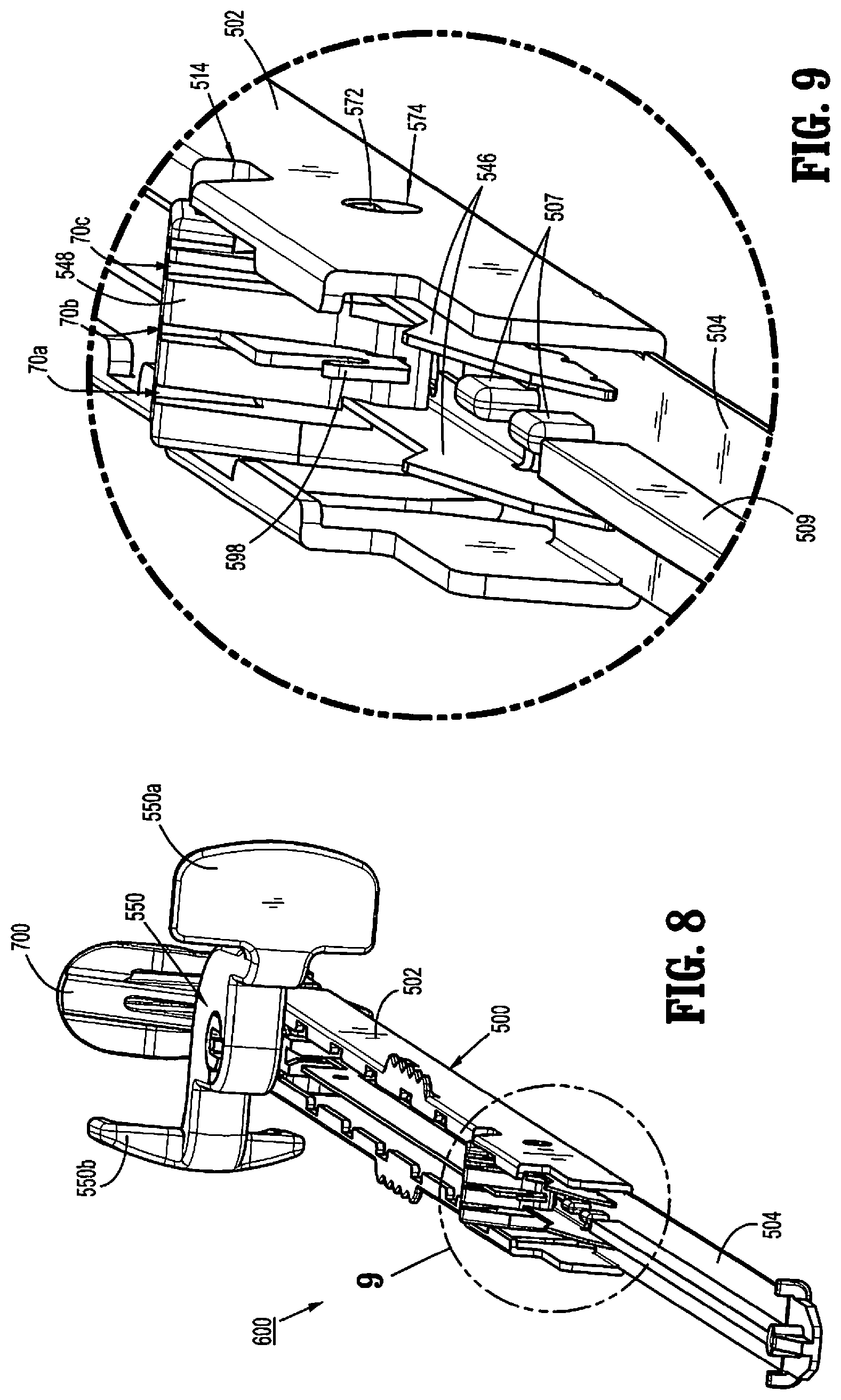
D00014

D00015

D00016

D00017

D00018

D00019

D00020

D00021

D00022

D00023

D00024

D00025

D00026

D00027

D00028

D00029

D00030

D00031

XML
uspto.report is an independent third-party trademark research tool that is not affiliated, endorsed, or sponsored by the United States Patent and Trademark Office (USPTO) or any other governmental organization. The information provided by uspto.report is based on publicly available data at the time of writing and is intended for informational purposes only.
While we strive to provide accurate and up-to-date information, we do not guarantee the accuracy, completeness, reliability, or suitability of the information displayed on this site. The use of this site is at your own risk. Any reliance you place on such information is therefore strictly at your own risk.
All official trademark data, including owner information, should be verified by visiting the official USPTO website at www.uspto.gov. This site is not intended to replace professional legal advice and should not be used as a substitute for consulting with a legal professional who is knowledgeable about trademark law.