Self-assembly cabinet
Chen , et al. Dec
U.S. patent number 10,506,876 [Application Number 15/884,873] was granted by the patent office on 2019-12-17 for self-assembly cabinet. This patent grant is currently assigned to E-MAKE Co., Ltd.. The grantee listed for this patent is Kung-Cheng Chen, Lung-Chuan Huang. Invention is credited to Kung-Cheng Chen, Lung-Chuan Huang.


| United States Patent | 10,506,876 |
| Chen , et al. | December 17, 2019 |
Self-assembly cabinet
Abstract
A self-assembly cabinet includes a box including a rectangular front frame, a rectangular rear frame, two rectangular side frames interconnecting the front frame and the rear frame, a top frame on tops of the front frame, the rear frame, and the side frames, and a bottom frame on bottoms of the front frame, the rear frame, and the side frames; a plurality of latches secured to four corners of an inner surface of each side frame respectively; and a plurality of cooperating fastening structures secured to four corners of an inner surface of each of the front frame and the rear frame respectively. The latches are releasably secured to the cooperating fastening structures respectively so that the side frames, the front frame, and the rear frame are assembled.
| Inventors: | Chen; Kung-Cheng (Taichung, TW), Huang; Lung-Chuan (Taichung, TW) | ||||||||||
|---|---|---|---|---|---|---|---|---|---|---|---|
| Applicant: |
|
||||||||||
| Assignee: | E-MAKE Co., Ltd. (Taichung,
TW) |
||||||||||
| Family ID: | 68841285 | ||||||||||
| Appl. No.: | 15/884,873 | ||||||||||
| Filed: | January 31, 2018 |
| Current U.S. Class: | 1/1 |
| Current CPC Class: | A47B 47/03 (20130101); F16B 5/0614 (20130101); A47B 55/00 (20130101); F16B 21/09 (20130101); A47B 47/047 (20130101); F16B 12/14 (20130101); F16B 2012/145 (20130101); A47B 2210/0005 (20130101); F16B 5/0036 (20130101) |
| Current International Class: | A47B 47/04 (20060101); A47B 55/00 (20060101); F16B 12/14 (20060101); F16B 5/06 (20060101) |
References Cited [Referenced By]
U.S. Patent Documents
| 4131376 | December 1978 | Busse |
| 4669910 | June 1987 | Koch |
| 2008/0042532 | February 2008 | Crabtree |
| 2010/0008744 | January 2010 | Tseng |
| 2011/0241510 | October 2011 | Lin |
| 2011/0290750 | December 2011 | Lim |
| 2012/0321378 | December 2012 | Velez, Jr. |
| 2015/0129728 | May 2015 | Tandjung |
| 2016/0258461 | September 2016 | Muller |
| 2016/0265218 | September 2016 | Gosling |
| 2016/0296014 | October 2016 | O'Connell, Jr. |
| 2017/0074307 | March 2017 | Slagle |
| 2017/0079426 | March 2017 | Davis |
| 2017/0321734 | November 2017 | Maertens |
| 2018/0092460 | April 2018 | Stack |
| 2018/0184802 | July 2018 | Lin |
Claims
What is claimed is:
1. A self-assembly cabinet comprising: a box including a rectangular front frame, a rectangular rear frame, two rectangular side frames interconnecting the front frame and the rear frame, a top frame on tops of the front frame, the rear frame, and the side frames, and a bottom frame on bottoms of the front frame, the rear frame, and the side frames; a plurality of latches secured to four corners of an inner surface of each side frame respectively; and a plurality of cooperating fastening structures secured to four corners of an inner surface of each of the front frame and the rear frame respectively; wherein the latches are releasably secured to the cooperating fastening structures respectively so that the side frames, the front frame, and the rear frame are configured to assemble; wherein each latch includes an extension having a concave member and a hook at an open end, and a plate member being at an angle of 90-degree with respect to the extension and threadedly secured to the side frame; wherein each cooperating fastening structure includes a plate element threadedly secured to the rear frame or the front frame, a cylindrical member projecting out of the plate element, and an enlargement at an open end of the cylindrical member; and wherein the concave member is put on the cylindrical member and the enlargement is configured to prevent the concave member from being disengaged from the cylindrical member.
2. The self-assembly cabinet of claim 1, further comprising at least one drawer each including two slides each provided on an inner surface of the side frame so that the drawer is configured to push in or pull out relative to the side frames.
3. The self-assembly cabinet of claim 1, further comprising two doors hingedly secured to two sides of the front frame respectively.
4. The self-assembly cabinet of claim 1, wherein size of the concave member is about the same as a diameter of the cylindrical member and a diameter of the enlargement is greater than the size of the concave member.
5. The self-assembly cabinet of claim 1, further comprising a plurality of 90-degree bent members threadedly secured to inner surfaces of the top frame, the side frames, and the bottom frame respectively.
6. The self-assembly cabinet of claim 1, further comprising a plurality of plates secured to the rear frame, the top frame, the bottom frame, and the side frames respectively.
Description
BACKGROUND OF THE INVENTION
1. Field of the Invention
The invention relates to cabinets and more particularly to a self-assembly cabinet having a plurality of latches and cooperating fastening structures releasably fastened together.
2. Description of Related Art
Self-assembly furniture (e.g., cabinet) is popular among consumers in recent decades. This is because it is easy to disassemble. Typically, a self-assembly cabinet is assembled by using screws, adhesives and/or dovetail joints. A person has to hold two adjacent components while joining them by above means. However, the components may fall or incline or a precise assembly is not possible due to shake and/or the weights of the components. And in turn, it causes a proper use of the cabinet to be impossible.
Thus, the need for improvement still exists.
SUMMARY OF THE INVENTION
It is therefore one object of the invention to provide a self-assembly cabinet comprising a box including a rectangular front frame, a rectangular rear frame, two rectangular side frames interconnecting the front frame and the rear frame, a top frame on tops of the front frame, the rear frame, and the side frames, and a bottom frame on bottoms of the front frame, the rear frame, and the side frames; a plurality of latches secured to four corners of an inner surface of each side frame respectively; and a plurality of cooperating fastening structures secured to four corners of an inner surface of each of the front frame and the rear frame respectively; wherein the latches are releasably secured to the cooperating fastening structures respectively so that the side frames, the front frame, and the rear frame are assembled.
The above and other objects, features and advantages of the invention will become apparent from the following detailed description taken with the accompanying drawings.
BRIEF DESCRIPTION OF THE DRAWINGS
FIG. 1 is a perspective view of a self-assembly cabinet according to a first preferred embodiment of the invention;
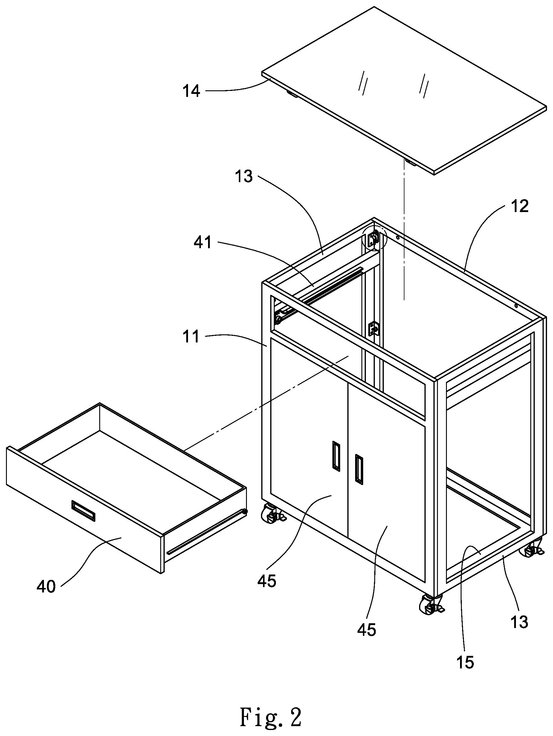
FIG. 2 is an exploded perspective view of the self-assembly cabinet;
FIG. 3 is an exploded view of the self-assembly cabinet without the doors and the drawer;
FIG. 4 is an enlarged perspective view showing the fastening of the latch and the cooperating fastening structure;
FIG. 5 is a perspective view showing the side frame to be secured to the rear frame by driving a screw through the 90-degree bent member on the side frame into the rear frame, and releasably fastening the latch and the cooperating fastening structure together;
FIG. 6 is a perspective view showing the side frame to be secured to the front frame by driving a screw through the 90-degree bent member on the side frame into the front frame, and releasably fastening the latch and the cooperating fastening structure together;
FIG. 7 is an enlarged longitudinal sectional view showing a fastening of the side frame, the rear frame and the top frame;
FIG. 8 is an enlarged longitudinal sectional view showing a fastening of the side frame, the front frame and the top frame; and
FIG. 9 is a perspective view of a self-assembly cabinet according to a second preferred embodiment of the invention.
DETAILED DESCRIPTION OF THE INVENTION
Referring to FIGS. 1 to 8, a self-assembly cabinet in accordance with a first preferred embodiment of the invention comprises a box 10, a plurality of latches 20, a plurality of cooperating fastening structures 30, a drawer 40, a pair of front doors 45, and a plurality of 90-degree bent members 50 as discussed in detail below.
The box 10 comprises a rectangular front frame 11, a rectangular rear frame 12, two rectangular side frames 13 interconnecting the front frame 11 and the rear frame 12, a top frame 14 on tops of the front frame 11, the rear frame 12, and the side frames 13, and a bottom frame 15 on bottoms of the front frame 11, the rear frame 12, and the side frames 13.
The box 10 further comprises a rear plate 121 secured to the rear frame 12, two side plates 131 secured to the side frames 13 respectively, a top plate 141 secured to top of the top frame 14, and a bottom plate 151 secured to bottom of the bottom frame 15. That is, top, bottom and two sides of the box 10 each have a plate secured thereto.
The latches 20 are secured to four corners of an inner surface of each side frame 13 respectively. The cooperating fastening structures 30 are secured to four corners of an inner surface of each of the front frame 11 and the rear frame 12 respectively (see FIGS. 2 to 6). The latch 20 is temporarily secured to the cooperating fastening structure 30.
The drawer 40 includes two slides 41 each provided on an inner surface of the side frame 13 so that the drawer 40 may be pushed in or pull out relative to the side frames 13. The doors 45 are hingedly secured to two sides of the front frame 11 respectively.
The 90-degree bent members 50 are provided on inner surfaces of the top frame 14, the side frames 13, and the bottom frame 15 respectively. Further, screws are used to secure the top frame 14, the side frames 13, the bottom frame 15, the front frame 11 and the rear frame 12 together.
As shown in FIG. 4, the latch 20 includes an extension 21 having a concave member 211 and a hook 212 at an open end; and a rectangular plate member 23 at an angle of 90-degree with respect to the extension 21 and threadedly secured to the side frame 13. The cooperating fastening structure 30 includes a plate element 32 threadedly secured to the rear frame 12 or the front frame 11, a cylindrical member 33 projecting out of the plate element 32, and an enlargement 31 at an open end of the cylindrical member 33. The concave member 211 is put on the cylindrical member 33 and the enlargement 31 is used to prevent the concave member 211 from being disengaged from the cylindrical member 33. The size of the concave member 211 is about the same as a diameter of the cylindrical member 33 and a diameter of the enlargement 31 is greater than the size of the concave member 211. This enables an easy assembly or disassembly of the box 10.
As shown in FIGS. 5 to 8 specifically, the latches 20 on the side frame 13 are secured to the cooperating fastening structures 30 on the front frame 11 and the rear frame 12 respectively. Thus, the front frame 11, the side frames 13 and the rear frame are joined. Further, two first screws are driven through the 90-degree bent members 50 on the side frame 13 into the rear frame 12, two second screws are driven through the 90-degree bent members 50 on the side frame 13 into the front frame 11, four third screws are driven through the 90-degree bent members 50 on the top frame 14 into the rear frame 12 and the front frame 11 respectively, and four fourth screws are driven through the 90-degree bent members 50 on the bottom frame 15 into the rear frame 12 and the front frame 11 respectively. As a result, the box 10 except the doors 45 is assembled. Optionally, four wheels (not numbered) are mounted on two ends of a bottom of the front frame 11 and two ends of a bottom of the rear frame 12 respectively.
Referring to FIG. 9, a self-assembly cabinet in accordance with a second preferred embodiment of the invention is shown. The characteristics of the second preferred embodiment are substantially the same as that of the first preferred embodiment except the following: a plurality of drawers 40 are provided and a handle 60 is secured to two ends of a top of the front frame 11.
It is envisaged by the invention that a quick and easy assembly or disassembly of the cabinet by using the latches 20 and the cooperating fastening structures 30 is made possible. Further, the components are precisely joined.
While the invention has been described in terms of preferred embodiments, those skilled in the art will recognize that the invention can be practiced with modifications within the spirit and scope of the appended claims.
* * * * *
D00000
D00001
D00002
D00003
D00004
D00005
D00006
D00007
D00008
XML
uspto.report is an independent third-party trademark research tool that is not affiliated, endorsed, or sponsored by the United States Patent and Trademark Office (USPTO) or any other governmental organization. The information provided by uspto.report is based on publicly available data at the time of writing and is intended for informational purposes only.
While we strive to provide accurate and up-to-date information, we do not guarantee the accuracy, completeness, reliability, or suitability of the information displayed on this site. The use of this site is at your own risk. Any reliance you place on such information is therefore strictly at your own risk.
All official trademark data, including owner information, should be verified by visiting the official USPTO website at www.uspto.gov. This site is not intended to replace professional legal advice and should not be used as a substitute for consulting with a legal professional who is knowledgeable about trademark law.