Constricted convection cooling for an electronic display
Dunn Dec
U.S. patent number 10,506,738 [Application Number 15/850,158] was granted by the patent office on 2019-12-10 for constricted convection cooling for an electronic display. This patent grant is currently assigned to Manufacturing Resources International, Inc.. The grantee listed for this patent is Manufacturing Resources International, Inc.. Invention is credited to William Dunn.


| United States Patent | 10,506,738 |
| Dunn | December 10, 2019 |
| **Please see images for: ( Certificate of Correction ) ** |
Constricted convection cooling for an electronic display
Abstract
A system for cooling an electronic display is provided. The electronic display has a posterior surface and is located in a housing. A constricted convection plate is located behind, and covers a majority of, the posterior surface. A channel is formed between the constricted convection plate and the posterior surface. A fan draws ambient air through the channel.
| Inventors: | Dunn; William (Alpharetta, GA) | ||||||||||
|---|---|---|---|---|---|---|---|---|---|---|---|
| Applicant: |
|
||||||||||
| Assignee: | Manufacturing Resources
International, Inc. (Alpharetta, GA) |
||||||||||
| Family ID: | 41116651 | ||||||||||
| Appl. No.: | 15/850,158 | ||||||||||
| Filed: | December 21, 2017 |
Prior Publication Data
| Document Identifier | Publication Date | |
|---|---|---|
| US 20180116073 A1 | Apr 26, 2018 | |
Related U.S. Patent Documents
| Application Number | Filing Date | Patent Number | Issue Date | ||
|---|---|---|---|---|---|
| 14923188 | Oct 26, 2015 | 9894800 | |||
| 14508621 | Oct 27, 2015 | 9173322 | |||
| 12411925 | Oct 7, 2014 | 8854595 | |||
| 12234307 | Jul 1, 2014 | 8767165 | |||
| 12234360 | Sep 19, 2008 | ||||
| 12237365 | Nov 4, 2014 | 8879042 | |||
| 12235200 | Sep 22, 2008 | ||||
| 61039454 | Mar 26, 2008 | ||||
| 61095615 | Sep 9, 2008 | ||||
| 61095616 | Sep 9, 2008 | ||||
| 61115333 | Nov 17, 2008 | ||||
| 61138736 | Dec 18, 2008 | ||||
| 61152879 | Feb 16, 2009 | ||||
| 61033064 | Mar 3, 2008 | ||||
| 61053713 | May 16, 2008 | ||||
| 61057599 | May 30, 2008 | ||||
| 61076126 | Jun 26, 2008 | ||||
| Current U.S. Class: | 1/1 |
| Current CPC Class: | H05K 7/20145 (20130101); H05K 7/20972 (20130101); G02F 1/133308 (20130101); H05K 7/202 (20130101); H05K 7/20154 (20130101); G02F 1/133385 (20130101); G02F 1/133603 (20130101); G02F 2001/133628 (20130101) |
| Current International Class: | H05K 7/20 (20060101); G02F 1/1333 (20060101); G02F 1/1335 (20060101) |
| Field of Search: | ;349/161 |
References Cited [Referenced By]
U.S. Patent Documents
| 4093355 | June 1978 | Kaplit et al. |
| 4593978 | June 1986 | Mourey et al. |
| 4634225 | January 1987 | Haim et al. |
| 4748765 | June 1988 | Martin |
| 4763993 | August 1988 | Vogeley et al. |
| 4921041 | May 1990 | Akachi |
| 4952783 | August 1990 | Aufderheide et al. |
| 4952925 | August 1990 | Haastert |
| 5029982 | July 1991 | Nash |
| 5088806 | February 1992 | McCartney et al. |
| 5247374 | September 1993 | Terada |
| 5282114 | January 1994 | Stone |
| 5293930 | March 1994 | Pitasi |
| 5351176 | September 1994 | Smith et al. |
| 5432526 | July 1995 | Hyatt |
| 5535816 | July 1996 | Ishida |
| 5559614 | September 1996 | Urbish et al. |
| 5621614 | April 1997 | O'Neill |
| 5657641 | August 1997 | Cunningham et al. |
| 5748269 | May 1998 | Harris et al. |
| 5765743 | June 1998 | Sakiura et al. |
| 5767489 | June 1998 | Ferrier |
| 5808418 | September 1998 | Pitman et al. |
| 5818010 | October 1998 | McCann |
| 5818694 | October 1998 | Daikoku et al. |
| 5835179 | November 1998 | Yamanaka |
| 5864465 | January 1999 | Liu |
| 5869818 | February 1999 | Kim |
| 5869919 | February 1999 | Sato et al. |
| 5903433 | May 1999 | Gudmundsson |
| 5991153 | November 1999 | Heady et al. |
| 6003015 | December 1999 | Kang et al. |
| 6007205 | December 1999 | Fujimori |
| 6043979 | March 2000 | Shim |
| 6089751 | July 2000 | Conover et al. |
| 6104451 | August 2000 | Matsuoka et al. |
| 6157432 | December 2000 | Helbing |
| 6181070 | January 2001 | Dunn et al. |
| 6191839 | February 2001 | Briley et al. |
| 6198222 | March 2001 | Chang |
| 6211934 | April 2001 | Habing et al. |
| 6215655 | April 2001 | Heady et al. |
| 6351381 | February 2002 | Bilski et al. |
| 6392727 | May 2002 | Larson et al. |
| 6417900 | July 2002 | Shin et al. |
| 6428198 | August 2002 | Saccomanno et al. |
| 6473150 | October 2002 | Takushima et al. |
| 6476883 | November 2002 | Salimes et al. |
| 6493440 | December 2002 | Gromatsky et al. |
| 6504713 | January 2003 | Pandolfi et al. |
| 6535266 | March 2003 | Nemeth et al. |
| 6628355 | September 2003 | Takahara |
| 6643130 | November 2003 | DeMarchis |
| 6714410 | March 2004 | Wellhofer |
| 6727468 | April 2004 | Nemeth |
| 6742583 | June 2004 | Tikka |
| 6825828 | November 2004 | Burke et al. |
| 6839104 | January 2005 | Taniguchi et al. |
| 6885412 | April 2005 | Ohnishi et al. |
| 6886942 | May 2005 | Okada et al. |
| 6891135 | May 2005 | Pala et al. |
| 6909486 | June 2005 | Wang et al. |
| 6943768 | September 2005 | Cavanaugh et al. |
| 6961108 | November 2005 | Wang et al. |
| 7015470 | March 2006 | Faytlin et al. |
| 7059757 | June 2006 | Shimizu |
| 7083285 | August 2006 | Hsu et al. |
| 7157838 | January 2007 | Thielemans et al. |
| 7161803 | January 2007 | Heady |
| 7190416 | March 2007 | Paukshto et al. |
| 7190587 | March 2007 | Kim et al. |
| 7209349 | April 2007 | Chien et al. |
| 7212403 | May 2007 | Rockenfeller |
| 7259964 | August 2007 | Yamamura et al. |
| 7269023 | September 2007 | Nagano |
| 7284874 | October 2007 | Jeong et al. |
| 7396145 | July 2008 | Wang et al. |
| 7452121 | November 2008 | Cho et al. |
| 7457113 | November 2008 | Kumhyr et al. |
| 7480140 | January 2009 | Hara et al. |
| 7535543 | May 2009 | Dewa et al. |
| 7591508 | September 2009 | Chang |
| 7602469 | October 2009 | Shin |
| D608775 | January 2010 | Leung |
| 7667964 | February 2010 | Kang et al. |
| 7752858 | July 2010 | Johnson et al. |
| 7753567 | July 2010 | Kang et al. |
| 7762707 | July 2010 | Kim et al. |
| 7800706 | September 2010 | Kim et al. |
| 7813124 | October 2010 | Karppanen |
| 7903416 | March 2011 | Chou |
| 7995342 | August 2011 | Nakamichi et al. |
| 8004648 | August 2011 | Dunn |
| 8035968 | October 2011 | Kwon et al. |
| 8081465 | December 2011 | Nishiura |
| 8102173 | January 2012 | Merrow |
| 8142027 | March 2012 | Sakai |
| 8208115 | June 2012 | Dunn |
| 8223311 | July 2012 | Kim et al. |
| 8241573 | August 2012 | Banerjee et al. |
| 8248784 | August 2012 | Nakamichi et al. |
| 8254121 | August 2012 | Lee et al. |
| 8269916 | September 2012 | Ohkawa |
| 8270163 | September 2012 | Nakamichi et al. |
| 8274622 | September 2012 | Dunn |
| 8274789 | September 2012 | Nakamichi et al. |
| 8300203 | October 2012 | Nakamichi et al. |
| 8320119 | November 2012 | Isoshima et al. |
| 8351014 | January 2013 | Dunn |
| 8358397 | January 2013 | Dunn |
| 8369083 | February 2013 | Dunn et al. |
| 8373841 | February 2013 | Dunn |
| 8379182 | February 2013 | Dunn |
| 8400608 | March 2013 | Takahashi et al. |
| 8472174 | June 2013 | Idems et al. |
| 8472191 | June 2013 | Yamamoto et al. |
| 8482695 | July 2013 | Dunn |
| 8497972 | July 2013 | Dunn et al. |
| 8649170 | February 2014 | Dunn et al. |
| 8649176 | February 2014 | Okada et al. |
| 8654302 | February 2014 | Dunn et al. |
| 8678603 | March 2014 | Zhang |
| 8693185 | April 2014 | Dunn et al. |
| 8700226 | April 2014 | Schuch et al. |
| 8711321 | April 2014 | Dunn et al. |
| 8749749 | June 2014 | Hubbard |
| 8755021 | June 2014 | Hubbard |
| 8758144 | June 2014 | Williams et al. |
| 8760613 | June 2014 | Dunn |
| 8767165 | July 2014 | Dunn |
| 8773633 | July 2014 | Dunn et al. |
| 8804091 | August 2014 | Dunn et al. |
| 8823916 | September 2014 | Hubbard et al. |
| 8854572 | October 2014 | Dunn |
| 8854595 | October 2014 | Dunn |
| 8879042 | November 2014 | Dunn |
| 8988647 | March 2015 | Hubbard |
| 9030641 | May 2015 | Dunn |
| 9089079 | July 2015 | Dunn |
| 9119325 | August 2015 | Dunn et al. |
| 9119330 | August 2015 | Hubbard et al. |
| 9173322 | October 2015 | Dunn |
| 9173325 | October 2015 | Dunn |
| 9282676 | March 2016 | Diaz |
| 9285108 | March 2016 | Dunn et al. |
| 9313917 | April 2016 | Dunn et al. |
| 9370127 | June 2016 | Dunn |
| 9448569 | September 2016 | Schuch et al. |
| 9451060 | September 2016 | Bowers et al. |
| 9451733 | September 2016 | Dunn et al. |
| 9456525 | September 2016 | Yoon et al. |
| 9470924 | October 2016 | Dunn et al. |
| 9500896 | November 2016 | Dunn et al. |
| 9516485 | December 2016 | Bowers et al. |
| 9549490 | January 2017 | Hubbard |
| 9594271 | March 2017 | Dunn et al. |
| 9613548 | April 2017 | DeMars |
| 9622392 | April 2017 | Bowers et al. |
| 9629287 | April 2017 | Dunn |
| 9648790 | May 2017 | Dunn et al. |
| 9655289 | May 2017 | Dunn et al. |
| 9723765 | August 2017 | DeMars |
| 9797588 | October 2017 | Dunn et al. |
| 9801305 | October 2017 | Dunn et al. |
| 9835893 | December 2017 | Dunn |
| 10194564 | January 2019 | Dunn et al. |
| 2001/0001459 | May 2001 | Savant et al. |
| 2001/0019454 | September 2001 | Tadic-Galeb et al. |
| 2002/0033919 | March 2002 | Sanelle et al. |
| 2002/0050793 | May 2002 | Cull et al. |
| 2002/0101553 | August 2002 | Enomoto et al. |
| 2002/0126248 | September 2002 | Yoshia |
| 2002/0148600 | October 2002 | Bosch et al. |
| 2002/0149714 | October 2002 | Anderson et al. |
| 2002/0154255 | October 2002 | Gromatzky et al. |
| 2002/0164944 | November 2002 | Haglid |
| 2002/0167637 | November 2002 | Burke et al. |
| 2003/0007109 | January 2003 | Park |
| 2003/0020884 | January 2003 | Okada et al. |
| 2003/0043091 | March 2003 | Takeuchi et al. |
| 2003/0104210 | June 2003 | Azumi et al. |
| 2003/0128511 | July 2003 | Nagashima et al. |
| 2003/0214785 | November 2003 | Perazzo |
| 2004/0012722 | January 2004 | Alvarez |
| 2004/0035558 | February 2004 | Todd et al. |
| 2004/0036834 | February 2004 | Ohnishi et al. |
| 2004/0042174 | March 2004 | Tomioka et al. |
| 2004/0103570 | June 2004 | Ruttenberg |
| 2004/0105159 | June 2004 | Saccomanno et al. |
| 2004/0165139 | August 2004 | Anderson et al. |
| 2004/0223299 | November 2004 | Ghosh |
| 2005/0012039 | January 2005 | Faytlin et al. |
| 2005/0012722 | January 2005 | Chon |
| 2005/0062373 | March 2005 | Kim et al. |
| 2005/0073632 | April 2005 | Dunn et al. |
| 2005/0073639 | April 2005 | Pan |
| 2005/0127796 | June 2005 | Olesen et al. |
| 2005/0134525 | June 2005 | Tanghe et al. |
| 2005/0134526 | June 2005 | Willem et al. |
| 2005/0213950 | September 2005 | Yoshimura |
| 2005/0229630 | October 2005 | Richter et al. |
| 2005/0237714 | October 2005 | Ebermann |
| 2005/0276053 | December 2005 | Nortrup et al. |
| 2005/0286131 | December 2005 | Saxena et al. |
| 2006/0012958 | January 2006 | Tomioka et al. |
| 2006/0018093 | January 2006 | Lai et al. |
| 2006/0034051 | February 2006 | Wang et al. |
| 2006/0056994 | March 2006 | Van Lear et al. |
| 2006/0082271 | April 2006 | Lee et al. |
| 2006/0092348 | May 2006 | Park |
| 2006/0125998 | June 2006 | Dewa et al. |
| 2006/0132699 | June 2006 | Cho et al. |
| 2006/0177587 | August 2006 | Ishizuka et al. |
| 2006/0199514 | September 2006 | Kimura |
| 2006/0209266 | September 2006 | Utsunomiya |
| 2006/0260790 | November 2006 | Theno et al. |
| 2006/0262079 | November 2006 | Seong et al. |
| 2006/0266499 | November 2006 | Choi et al. |
| 2006/0269216 | November 2006 | Wiemeyer et al. |
| 2006/0283579 | December 2006 | Ghosh et al. |
| 2007/0013647 | January 2007 | Lee et al. |
| 2007/0019419 | January 2007 | Hafuka et al. |
| 2007/0030879 | February 2007 | Hatta |
| 2007/0047239 | March 2007 | Kang |
| 2007/0065091 | March 2007 | Hinata et al. |
| 2007/0076431 | April 2007 | Atarashi et al. |
| 2007/0103863 | May 2007 | Kim |
| 2007/0103866 | May 2007 | Park |
| 2007/0115686 | May 2007 | Tyberghien |
| 2007/0139929 | June 2007 | Yoo et al. |
| 2007/0140671 | June 2007 | Yoshimura |
| 2007/0151274 | July 2007 | Roche et al. |
| 2007/0151664 | July 2007 | Shin |
| 2007/0171353 | July 2007 | Hong |
| 2007/0206158 | September 2007 | Kinoshita et al. |
| 2007/0211205 | September 2007 | Shibata |
| 2007/0212211 | September 2007 | Chiyoda et al. |
| 2007/0217221 | September 2007 | Lee et al. |
| 2007/0237636 | October 2007 | Hsu |
| 2007/0267174 | November 2007 | Kim |
| 2008/0035315 | February 2008 | Han |
| 2008/0055534 | March 2008 | Kawano |
| 2008/0076342 | March 2008 | Bryant et al. |
| 2008/0099193 | May 2008 | Aksamit et al. |
| 2008/0148609 | June 2008 | Ogoreve |
| 2008/0209934 | September 2008 | Richards |
| 2008/0218446 | September 2008 | Yamanaka |
| 2008/0236005 | October 2008 | Isayev et al. |
| 2008/0267790 | October 2008 | Gaudet et al. |
| 2008/0283234 | November 2008 | Sagi et al. |
| 2008/0285290 | November 2008 | Ohashi et al. |
| 2008/0310116 | December 2008 | O'Connor |
| 2009/0009047 | January 2009 | Yanagawa et al. |
| 2009/0009729 | January 2009 | Sakai |
| 2009/0086430 | April 2009 | Kang et al. |
| 2009/0120629 | May 2009 | Ashe |
| 2009/0122218 | May 2009 | Oh et al. |
| 2009/0126906 | May 2009 | Dunn |
| 2009/0126907 | May 2009 | Dunn |
| 2009/0126914 | May 2009 | Dunn |
| 2009/0135365 | May 2009 | Dunn |
| 2009/0147170 | June 2009 | Oh et al. |
| 2009/0154096 | June 2009 | Iyengar et al. |
| 2009/0174626 | July 2009 | Isoshima et al. |
| 2009/0231807 | September 2009 | Bouissiere |
| 2009/0244472 | October 2009 | Dunn |
| 2009/0279240 | November 2009 | Karppanen |
| 2009/0302727 | December 2009 | Vincent et al. |
| 2009/0306820 | December 2009 | Simmons et al. |
| 2010/0060861 | March 2010 | Medin |
| 2010/0079949 | April 2010 | Nakamichi et al. |
| 2010/0162747 | July 2010 | Hamel et al. |
| 2010/0171889 | July 2010 | Pantel et al. |
| 2010/0182562 | July 2010 | Yoshida et al. |
| 2010/0220249 | September 2010 | Nakamichi et al. |
| 2010/0226091 | September 2010 | Dunn |
| 2010/0232107 | September 2010 | Dunn |
| 2010/0238394 | September 2010 | Dunn |
| 2010/0321887 | December 2010 | Kwon et al. |
| 2011/0001898 | January 2011 | Mikubo et al. |
| 2011/0013114 | January 2011 | Dunn et al. |
| 2011/0019363 | January 2011 | Vahlsing et al. |
| 2011/0051071 | March 2011 | Nakamichi et al. |
| 2011/0058326 | March 2011 | Idems et al. |
| 2011/0072697 | March 2011 | Miller |
| 2011/0075361 | March 2011 | Nakamichi et al. |
| 2011/0083460 | April 2011 | Thomas et al. |
| 2011/0083824 | April 2011 | Rogers |
| 2011/0085301 | April 2011 | Dunn |
| 2011/0114384 | May 2011 | Sakamoto et al. |
| 2011/0116000 | May 2011 | Dunn et al. |
| 2011/0122162 | May 2011 | Sato et al. |
| 2011/0141724 | June 2011 | Erion |
| 2011/0261523 | October 2011 | Dunn et al. |
| 2012/0006523 | January 2012 | Masahiro et al. |
| 2012/0012295 | January 2012 | Kakiuchi et al. |
| 2012/0012300 | January 2012 | Dunn et al. |
| 2012/0014063 | January 2012 | Weiss |
| 2012/0020114 | January 2012 | Miyamoto et al. |
| 2012/0038849 | February 2012 | Dunn et al. |
| 2012/0044217 | February 2012 | Okada et al. |
| 2012/0106081 | May 2012 | Hubbard et al. |
| 2012/0188481 | July 2012 | Kang et al. |
| 2012/0206687 | August 2012 | Dunn et al. |
| 2012/0249402 | October 2012 | Kang |
| 2012/0255704 | October 2012 | Nakamichi |
| 2012/0274876 | November 2012 | Cappaert et al. |
| 2012/0284547 | November 2012 | Culbert et al. |
| 2013/0170140 | July 2013 | Dunn |
| 2013/0176517 | July 2013 | Kim et al. |
| 2013/0201685 | August 2013 | Messmore et al. |
| 2013/0258659 | October 2013 | Erion |
| 2013/0294039 | November 2013 | Chao |
| 2014/0085564 | March 2014 | Hendren et al. |
| 2014/0111758 | April 2014 | Dunn et al. |
| 2014/0113540 | April 2014 | Dunn et al. |
| 2014/0313698 | October 2014 | Dunn et al. |
| 2014/0314395 | October 2014 | Dunn et al. |
| 2015/0264826 | September 2015 | Dunn et al. |
| 2015/0319882 | November 2015 | Dunn et al. |
| 2015/0366101 | December 2015 | Dunn et al. |
| 2016/0041423 | February 2016 | Dunn |
| 2016/0044829 | February 2016 | Dunn |
| 2016/0192536 | June 2016 | Diaz |
| 2016/0195254 | July 2016 | Dunn et al. |
| 2016/0198588 | July 2016 | DeMars |
| 2016/0238876 | August 2016 | Dunn et al. |
| 2016/0242329 | August 2016 | DeMars |
| 2016/0242330 | August 2016 | Dunn |
| 2016/0249493 | August 2016 | Dunn et al. |
| 2016/0302331 | October 2016 | Dunn |
| 2017/0023823 | January 2017 | Dunn et al. |
| 2017/0068042 | March 2017 | Dunn et al. |
| 2017/0074453 | March 2017 | Bowers et al. |
| 2017/0083043 | March 2017 | Bowers et al. |
| 2017/0083062 | March 2017 | Bowers et al. |
| 2017/0111486 | April 2017 | Bowers et al. |
| 2017/0111520 | April 2017 | Bowers et al. |
| 2017/0111521 | April 2017 | Bowers et al. |
| 2017/0127579 | May 2017 | Hubbard |
| 2017/0188490 | June 2017 | Dunn et al. |
| 2017/0245400 | August 2017 | Dunn et al. |
| 2017/0257978 | September 2017 | Diaz |
| 2017/0332523 | November 2017 | DeMars |
| 2019/0037738 | January 2019 | Dunn et al. |
| 2011248190 | May 2011 | AU | |||
| 2017216500 | Jan 2019 | AU | |||
| 2702363 | May 2005 | CN | |||
| 107251671 | Oct 2017 | CN | |||
| 1408476 | Apr 2004 | EP | |||
| 1647766 | Apr 2006 | EP | |||
| 1762892 | Mar 2007 | EP | |||
| 1951020 | Jul 2008 | EP | |||
| 2225603 | Sep 2010 | EP | |||
| 2370987 | Oct 2011 | EP | |||
| 2603831 | Jun 2013 | EP | |||
| 2801888 | Nov 2014 | EP | |||
| 2909829 | Aug 2015 | EP | |||
| 3020260 | May 2016 | EP | |||
| 3117693 | Jan 2017 | EP | |||
| 2402205 | Dec 2004 | GB | |||
| 402062015 | Mar 1990 | JP | |||
| 402307080 | Dec 1990 | JP | |||
| 3153212 | Jul 1991 | JP | |||
| H06-2337 | Jan 1994 | JP | |||
| 6082745 | Mar 1994 | JP | |||
| 8115788 | May 1996 | JP | |||
| 8194437 | Jul 1996 | JP | |||
| H08-305301 | Nov 1996 | JP | |||
| 8339034 | Dec 1996 | JP | |||
| H09246766 | Sep 1997 | JP | |||
| 11160727 | Jun 1999 | JP | |||
| H11296094 | Oct 1999 | JP | |||
| 2000010501 | Jan 2000 | JP | |||
| 2001209126 | Aug 2001 | JP | |||
| 2002158475 | May 2002 | JP | |||
| 2004053749 | Feb 2004 | JP | |||
| 2004199675 | Jul 2004 | JP | |||
| 2004286940 | Oct 2004 | JP | |||
| 2005017556 | Jan 2005 | JP | |||
| 2000131682 | May 2005 | JP | |||
| 2005134849 | May 2005 | JP | |||
| 2005265922 | Sep 2005 | JP | |||
| 2006513577 | Apr 2006 | JP | |||
| 2007322718 | May 2006 | JP | |||
| 2006148047 | Jun 2006 | JP | |||
| 2006163217 | Jun 2006 | JP | |||
| 2007003638 | Jan 2007 | JP | |||
| 2001-293105 | Nov 2007 | JP | |||
| 09307257 | Nov 2007 | JP | |||
| 2008010361 | Jan 2008 | JP | |||
| 2008292743 | Dec 2008 | JP | |||
| 2010024624 | Feb 2010 | JP | |||
| 2010102227 | May 2010 | JP | |||
| 2011503663 | Jan 2011 | JP | |||
| 2011075819 | Apr 2011 | JP | |||
| 2012133254 | Jul 2012 | JP | |||
| 2013537721 | Oct 2013 | JP | |||
| 2014225595 | Dec 2014 | JP | |||
| 2017518526 | Jul 2017 | JP | |||
| 20000000118 | Jan 2000 | KR | |||
| 20000047899 | Jul 2000 | KR | |||
| 1020040067701 | Jul 2004 | KR | |||
| 200366674 | Nov 2004 | KR | |||
| 20050033986 | Apr 2005 | KR | |||
| 200401354 | Nov 2005 | KR | |||
| 20060016469 | Feb 2006 | KR | |||
| 100666961 | Jan 2007 | KR | |||
| 1020070070675 | Apr 2007 | KR | |||
| 1020070048294 | Aug 2007 | KR | |||
| 101764381 | Jul 2017 | KR | |||
| 2513043 | Apr 2014 | RU | |||
| WO2005079129 | Aug 2005 | WO | |||
| WO2007116116 | Oct 2007 | WO | |||
| WO2008050660 | May 2008 | WO | |||
| WO2009065125 | May 2009 | WO | |||
| WO2009065125 | May 2009 | WO | |||
| WO2009135308 | Nov 2009 | WO | |||
| WO2010007821 | Feb 2010 | WO | |||
| WO2010080624 | Jul 2010 | WO | |||
| WO2011069084 | Jun 2011 | WO | |||
| WO2011072217 | Jun 2011 | WO | |||
| WO2011140179 | Nov 2011 | WO | |||
| WO2011150078 | Dec 2011 | WO | |||
| WO2012021573 | Feb 2012 | WO | |||
| WO2012024426 | Feb 2012 | WO | |||
| 2013182733 | Dec 2013 | WO | |||
| WO2014149773 | Sep 2014 | WO | |||
| WO2014150036 | Sep 2014 | WO | |||
| WO2015168375 | Nov 2015 | WO | |||
| WO2016102982 | Jun 2016 | WO | |||
| WO2016133852 | Aug 2016 | WO | |||
| WO2017152166 | Sep 2017 | WO | |||
Other References
|
Itsenclosures, Product Catalog, 2009, 48 pages. cited by applicant . Itsenclosures, Standard Product Data Sheet, 2011, 18 pages. cited by applicant . Sunbritetv, All Weather Outdoor LCD Television Model 4610HD, 2008, 1 page. cited by applicant . Sunbritetv, Introduces Two New All-Weather Outdoor Televisions InfoComm 2008, 7 pages. cited by applicant . Itsenclosures, Viewstation, 2017, 16 pages. cited by applicant . Novitsky, Driving LEDs versus CCFLs for LCD backlighting, Nov. 12, 2007, 6 pages. cited by applicant . Federman, Cooling Flat Panel Displays, 2011, 4 pages. cited by applicant . Zeeff, T.M., EMC analysis of an 18'' LCD monitor, 2000, 1 page. cited by applicant . Wankhede, Evaluation of Cooling Solutions for Outdoor Electronics, Sep. 17-19, 2007, 6 pages. cited by applicant . Bureau of Ships Navy Department, Guide Manual of Cooling methods for Electronic Equipment, Mar. 31, 1955, 212 pages. cited by applicant . Scott, Cooling of Electronic Equipment, Apr. 4, 1947, 119 pages. cited by applicant . Sergent, Thermal Management Handbook for Electronic Assemblies, Aug. 14, 1998, 190 pages. cited by applicant . Steinberg, Cooling Techniques for Electronic Equipment First Edition, 1980, 255 pages. cited by applicant . Steinberg, Cooling Techniques for Electronic Equipment Second Edition, 1991, 299 pages. cited by applicant . Yeh, Thermal Management of Microelectronic Equipment, Oct. 15, 2002, 148 pages. cited by applicant . Mentley, David E., State of Flat-Panel Display Technology and Future Trends, Proceedings of the IEEE, Apr. 2002, vol. 90, No. 4, pp. 453-459. cited by applicant . Rohsenow, Warren M., Handbook of Heat Transfer, Third Edition, 1998, select chapters, 112 pages, McGraw-Hill. cited by applicant . The American Heritage College Dictionary, Third Edition, 1993, excerpt, 3 pages, Houghton Mifflin Company. cited by applicant . Civiq Smartscapes LLC. V Manufacturing Resources International, Inc., Petition for Inter Partes Review of U.S. Pat. No. 8,854,572 including Declaration of Greg Blonder in Support of Petition, Curriculum Vitae of Greg Blonder and Prosecution History of U.S. Pat. No. 8,854,572, Petition filed Mar. 14, 2018, 427 pages. cited by applicant . Civiq, Invalidity Contentions, Jan. 24, 2018, 51 pages. cited by applicant . Civiq, Invalidity Claim Chart, Appendix I, Mar. 22, 2018, 4 pages. cited by applicant . Civiq, Invalidity Claim Charts, Appendix A-Appendix D, Jan. 24, 2018, 51 pages. cited by applicant . Civiq, Invalidity Claim Charts, Appendix F to H, Mar. 22, 2018, 18 pages. cited by applicant . Yung, Using Metal Core Printed Circuit Board as a Solution for Thermal Management article, 2007, 5 pages. cited by applicant . Civiq Smartscapes LLC. V Manufacturing Resources International, Inc., Defendants Amended Answer and Countercliams to Plaintiff's First Amended Complaint, Filed Apr. 24, 2018, 240 pages. cited by applicant . Anandan, Munismay, Progress of LED backlights for LCDs, Journal of the SID, 2008, pp. 287-310, 16/2. cited by applicant. |
Primary Examiner: Blevins; Jerry M
Attorney, Agent or Firm: Standley Law Group LLP Standley; Jeffrey S. Smith; Adam J.
Parent Case Text
CROSS-REFERENCE TO RELATED APPLICATIONS
This application is a continuation of U.S. application Ser. No. 14/923,188 filed on Oct. 26, 2015, which is a continuation of U.S. application Ser. No. 14/508,621 filed on Oct. 7, 2014, now U.S. Pat. No. 9,173,322 issued on Oct. 27, 2015, which is a continuation of U.S. application Ser. No. 12/411,925 filed on Mar. 26, 2009, now U.S. Pat. No. 8,854,595 issued Oct. 7, 2014. U.S. application Ser. No. 12/411,925 is a non-provisional application of U.S. Provisional Application No. 61/039,454 filed Mar. 26, 2008. U.S. application Ser. No. 12/411,925 is a non-provisional application of U.S. Provisional Application No. 61/095,615 filed Sep. 9, 2008. U.S. application Ser. No. 12/411,925 is a non-provisional application of U.S. Provisional Application No. 61/095,616 filed Sep. 9, 2008. U.S. application Ser. No. 12/411,925 is a non-provisional application of U.S. Provisional Application No. 61/115,333 filed Nov. 17, 2008. U.S. application Ser. No. 12/411,925 is a non-provisional application of U.S. Provisional Application No. 61/138,736 filed Dec. 18, 2008. U.S. application Ser. No. 12/411,925 is a non-provisional application of U.S. Provisional Application No. 61/152,879 filed Feb. 16, 2009. U.S. application Ser. No. 12/411,925 is also continuation-in-part of U.S. application Ser. No. 12/234,307 filed Sep. 19, 2008, now U.S. Pat. No. 8,767,165 issued Jul. 1, 2014, which is a non-provisional application of U.S. Provisional Application No. 61/033,064 filed Mar. 3, 2008. U.S. application Ser. No. 12/411,925 is also a continuation-in-part of U.S. application Ser. No. 12/234,360 filed Sep. 19, 2008, which is a non-provisional application of U.S. Provisional Application No. 61/053,713 filed May 16, 2008. U.S. application Ser. No. 12/411,925 is also a continuation-in-part of U.S. application Ser. No. 12/237,365 filed Sep. 24, 2008, now U.S. Pat. No. 8,879,042 issued Nov. 4, 2014, which is a non-provisional application of U.S. Provisional Application No. 61/057,599 filed May 30, 2008. U.S. application Ser. No. 12/411,925 is also a continuation-in-part of U.S. application Ser. No. 12/235,200 filed Sep. 22, 2008, which is a non-provisional application of U.S. Provisional Application No. 61/076,126 filed Jun. 26, 2008. All aforementioned applications are hereby incorporated by reference in their entirety as if fully cited herein.
Claims
The invention claimed is:
1. A cooling system comprising: an electronic display comprising a backlight having a posterior surface; a housing for the electronic display; a constricted convection plate placed within the housing, spaced apart from the electronic display, and posterior to the posterior surface of the backlight, wherein the constricted convection plate covers at least the majority of the posterior surface; a channel formed between the constricted convection plate and the posterior surface; and a plurality of fans positioned along the channel to draw in ambient air and generate a substantially uniform flow of the ingested ambient air through the channel.
2. The cooling system from claim 1 further comprising: at least one electronic component for operating the electronic display located on the constricted convection plate such that the electronic component is located outside of the channel.
3. The cooling system from claim 1 wherein: the electronic display is a liquid crystal display.
4. The cooling system from claim 1 wherein: the constricted convection plate is substantially parallel to the posterior display surface.
5. The cooling system from claim 4 wherein: the constricted convection plate has substantially the same surface area as the posterior display surface.
6. The cooling system from claim 1 further comprising: at least one bracket which connects the posterior display surface with the constricted convection plate.
7. The cooling system from claim 1 further comprising: a heat sink placed within the channel.
8. The cooling system from claim 1 further comprising: a first side panel and a second side panel, wherein the first and second side panels are spaced apart from one another and extend between the posterior display surface and the constricted convection plate to further define the channel.
9. A cooling system for a liquid crystal display (LCD) comprising: a liquid crystal stack; a backlight assembly located behind the liquid crystal stack and comprising: a printed circuit board (PCB) having front and back sides, a plurality of LEDs mounted on the front side of the PCB, and a posterior surface on the rear side of the PCB; a constricted convection plate positioned behind, spaced apart from, and substantially parallel to the posterior surface of the PCB; a channel defined by the spaced between the constricted convection plate and the posterior surface of the PCB; and a number of fans positioned along the channel to draw in air and generate a substantially uniform flow of the ingested air across the channel to facilitate substantially uniform cooling of the backlight assembly.
10. The LCD from claim 9 further comprising: at least one bracket which connects the posterior surface with the constricted convection plate.
11. The LCD from claim 9 further comprising: a housing for the liquid crystal stack, backlight assembly, constricted convection plate, and fan; and an entrance aperture within the housing which permits ambient air to enter the housing and flow between the constricted convection plate and the posterior surface of the PCB.
12. The LCD from claim 9 wherein: the constricted convection plate covers a majority of the posterior surface of the PCB.
13. The LCD from claim 9 further comprising: a first and second side panel, wherein said side panels extend from either side of the posterior surface of the PCB to the respective side of the constricted convection plate, wherein the side panels are positioned substantially parallel with one another and further define the channel.
14. An electronic display assembly comprising: an electronic display comprising a front surface and a posterior surface; a constricted convection plate behind, spaced apart from, and substantially parallel with the posterior surface of the display, wherein the constricted convection plate covers a majority of the posterior surface; a housing containing the electronic display and the constricted convection plate; a fan positioned to force ambient air through a channel defined by the constricted convection plate and the posterior surface; and at least one electronic component located on the constricted convection plate such that the electronic component is positioned outside of the channel; wherein the constricted convection plate provides a thermal barrier between the at least one electronic device and the electronic display.
15. The electronic display assembly from claim 14 wherein: the at least one electronic component is for operating the electronic display.
16. The electronic display assembly from claim 14 further comprising: at least one bracket connecting the posterior surface with the constricted convection plate.
17. The electronic display assembly from claim 14 further comprising: a gaseous closed loop traveling across the front display surface, between the constricted convection plate and the housing, and returning to the front display surface; and a fan positioned to propel gas around the closed loop.
18. The electronic display assembly from claim 14 wherein: the electronic display comprises a liquid crystal display having a backlight assembly; and the posterior surface is the rear surface of the backlight assembly.
19. The electronic display assembly from claim 14 further comprising: a pair of sidewalls extending between the posterior surface and the constricted convection plate on opposite side thereof and substantially parallel to one another so as to further define the channel.
Description
TECHNICAL FIELD
Exemplary embodiments generally relate to cooling systems and in particular to cooling systems for electronic displays.
BACKGROUND OF THE ART
Conductive and convective heat transfer systems for electronic displays are known. These systems of the past generally attempt to remove heat from the electronic components in a display through as many sidewalls of the display as possible. In order to do this, the systems of the past have relied primarily on fans for moving air past the components to be cooled and out of the display. In some cases, the heated air is moved into convectively thermal communication with fins. Some of the past systems also utilize conductive heat transfer from heat producing components directly to heat conductive housings for the electronics. In these cases, the housings have a large surface area, which is in convective communication with ambient air outside the housings. Thus, heat is transferred convectively or conductively to the housing and is then transferred into the ambient air from the housing by natural convection.
While such heat transfer systems have enjoyed a measure of success in the past, improvements to displays require even greater cooling capabilities.
SUMMARY OF THE EXEMPLARY EMBODIMENTS
In particular, cooling devices for electronic displays of the past have generally used convective heat dissipation systems that function to cool an entire interior of the display by one or more fans and fins, for example. By itself, this is not adequate in many climates, especially when radiative heat transfer from the sun through a display window becomes a major factor. In many applications and locations 200 Watts or more of power through such a display window is common. Furthermore, the market is demanding larger screen sizes for displays. With increased electronic display screen size and corresponding display window size more heat will be generated and more heat will be transmitted into the displays.
In the past, many displays have functioned satisfactorily with ten or twelve inch screens. Now, many displays are in need of screens having sizes greater than or equal to twenty-four inches that may require improved cooling systems. For example, some outdoor applications call for seventy inch screens and above. With increased heat production with the larger screens and radiative heat transfer from the sun through the display window, heat dissipation systems of the past, which attempt to cool the entire interior of the display with fins and fans, are no longer adequate.
A large fluctuation in temperature is common in the devices of the past. Such temperature fluctuation adversely affects the electronic components in these devices. Whereas the systems of the past attempted to remove heat from the entire interior of the display, a preferred embodiment causes directed convective heat transfer from the anterior of the display. By the aspects described below, the present invention has made consistent cooling possible for electronic displays having screens of sizes greater than or equal to twelve inches. For example, cooling of a seventy inch screen can be achieved, even in extremely hot climates. Greater cooling capabilities are provided by the device and method described and shown in more detail below.
An exemplary embodiment relates to a constricted convection cooling system and a method of cooling an electronic display. An exemplary embodiment includes an external housing and a constricted convection plate. The external housing preferably includes an air entrance end and an exhaust end. The air entrance end defines an entrance aperture; while the exhaust end defines an exit aperture. The constricted convection plate is preferably mounted to the posterior display surface. This posterior display surface may be the posterior surface of the backlight assembly or the posterior surface of any other thin panel display assembly (OLED, plasma, etc.). The constricted convection plate further defines a constricted convection cooling channel immediately behind the posterior display surface. The convection cooling channel may be adapted to receive air entering the entrance aperture and adapted to expel air through the exit aperture.
The air entering the constricted convection cooling channel may be from a refrigerated air source in communication with the entrance opening, or alternatively may be ambient air from the display surroundings. A septum in association with the external housing may be adapted to direct air into the constricted convection cooling channel. One or more fans may be used to draw the cooling air through the constricted convection cooling channel. In other embodiments, one or more fans may be used to force air through the constricted convection cooling channel. In exemplary embodiments, a plurality of fans are used to draw a substantially uniform flow of air through the constricted convection cooling channel. This helps to cool the display assembly in a uniform manner. This is particularly beneficial with an LED backlight, as individual LEDs may fail prematurely if exposed to high levels of heat for an extended period of time.
The foregoing and other features and advantages will be apparent from the following more detailed description of the particular embodiments, as illustrated in the accompanying drawings.
BRIEF DESCRIPTION OF THE DRAWINGS
A better understanding of an exemplary embodiment will be obtained from a reading of the following detailed description and the accompanying drawings wherein identical reference characters refer to identical parts and in which:
FIG. 1 is a perspective view of a display that may be used in an exemplary embodiment.
FIG. 2 is a posterior view of a display that may be used in an exemplary embodiment.
FIG. 3 is a perspective view of the constricted convection plate.
FIG. 4 is an exploded view of a display that may be used in an exemplary embodiment and an exemplary embodiment of the constricted convection plate.
FIG. 5A is a front perspective view of a fan and display that may be used in an exemplary embodiment and an exemplary embodiment of the constricted convection plate.
FIGS. 5B through 5F show side views of additional embodiments for the constricted convection system.
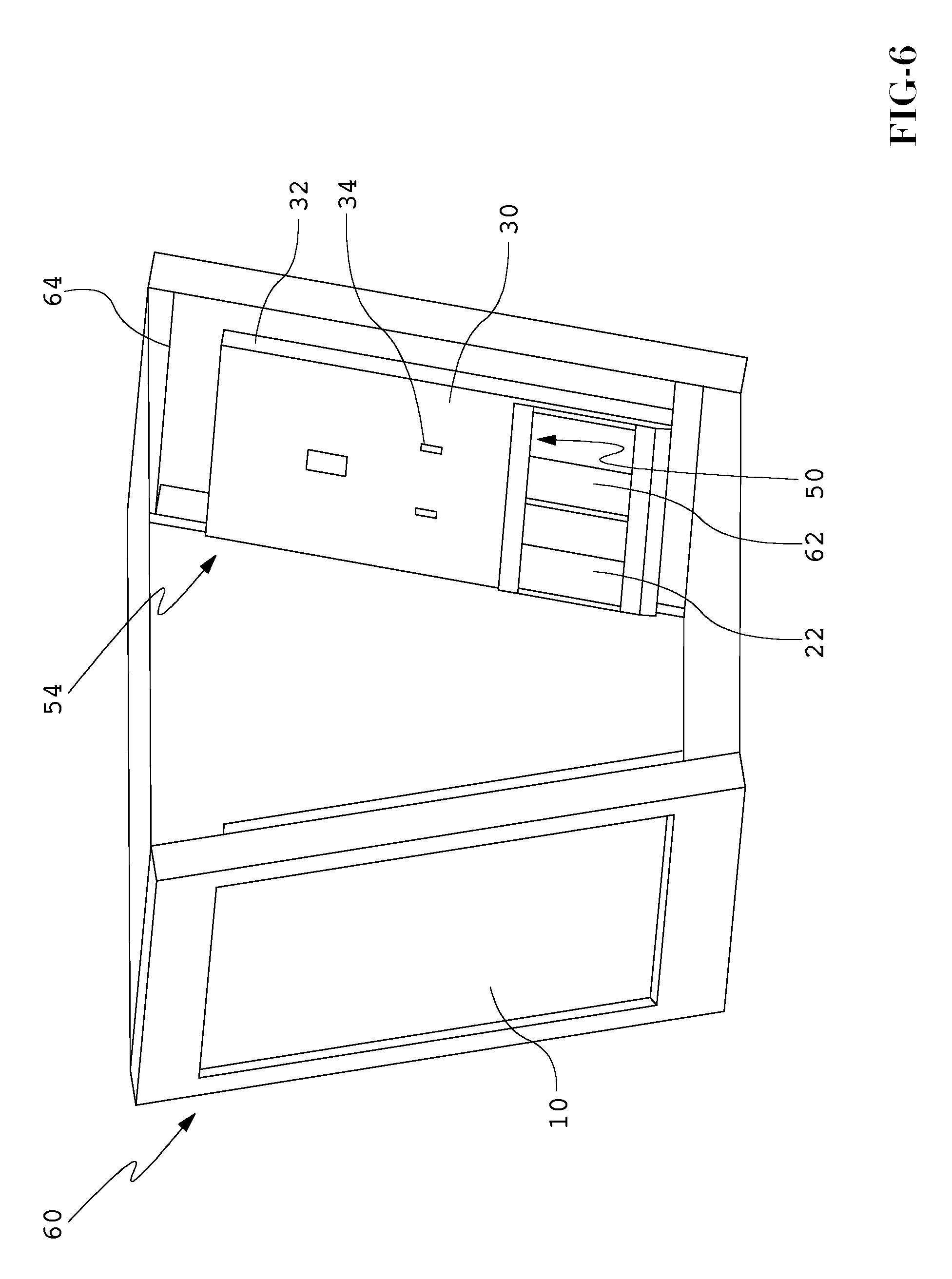
FIG. 6 is a perspective view of a double display housing utilizing an exemplary embodiment of the constricted convection air cooling system for an electronic display.
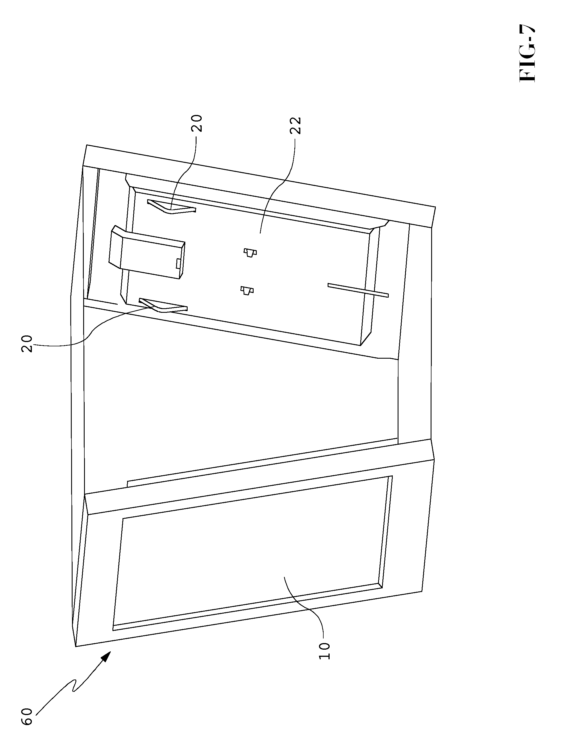
FIG. 7 is a posterior view of a display the may be found in a double display housing utilizing an exemplary embodiment of the constricted convection air cooling system for an electronic display.
FIG. 8 is an exploded view of an exemplary embodiment of the constricted convection air cooling system for an electronic display.
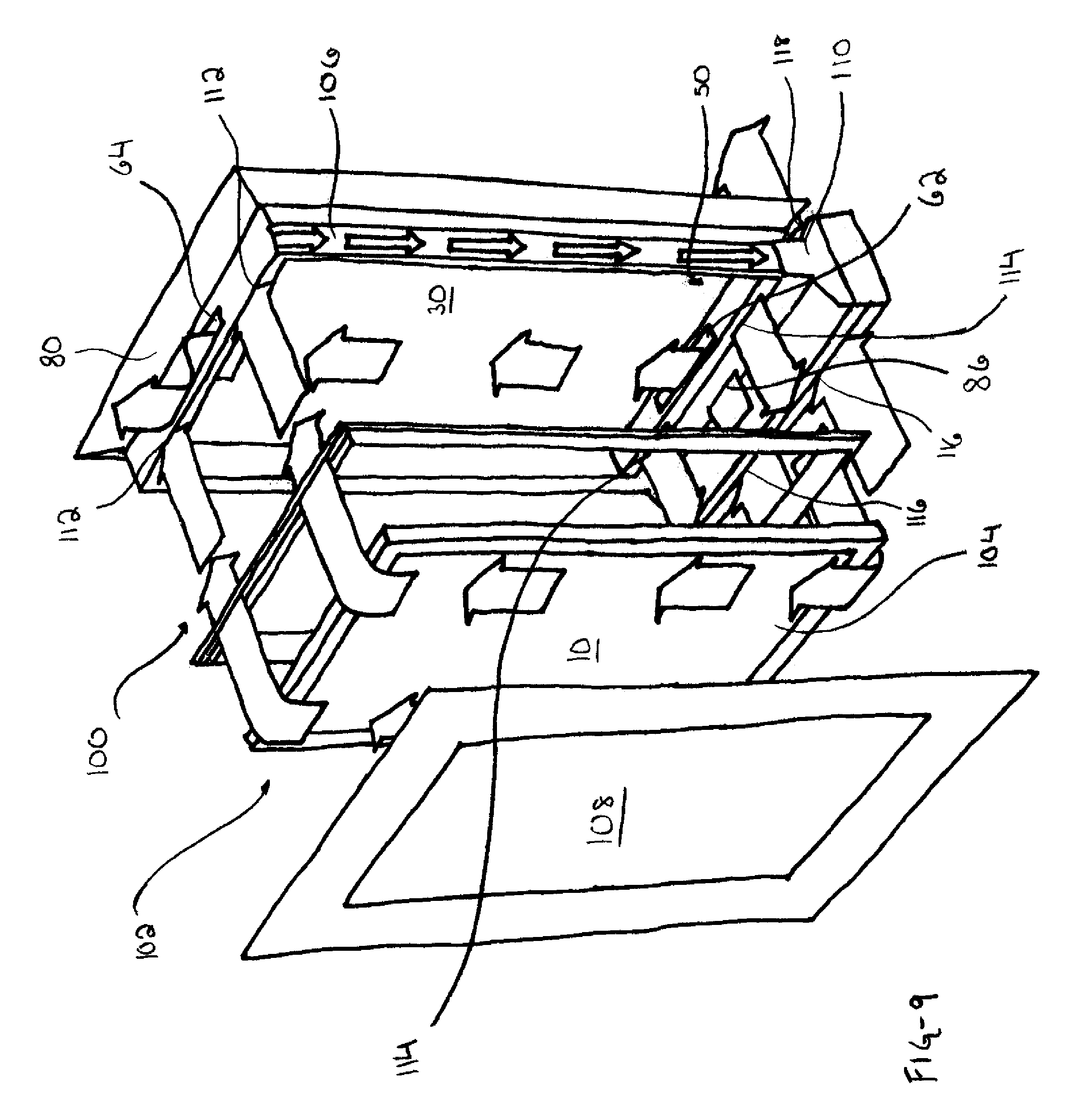
FIG. 9 is a perspective view of an exemplary embodiment of the constricted air cooling system for an electronic display of the present invention with an optional isolated gas cooling system.
DETAILED DESCRIPTION
Exemplary embodiments relate to a cooling system for an electronic display and to combinations of the cooling system and the electronic display. Exemplary embodiments provide a constricted convection cooling system for an electronic display.
FIG. 1 is a perspective view of a display that may be used in an exemplary embodiment. As may be appreciated, when the display 10 is exposed to heat and/or sunlight, the temperatures inside the display 10 will vary greatly without some kind of cooling device. As such, the electronics including the display screen 12 (e.g., LCD screen) will have a greatly reduced life span. By implementing certain embodiments of the cooling system disclosed herein, temperature fluctuation is greatly reduced. This cooling capability has been achieved in spite of the fact that larger screens generate more heat than smaller screens.
The display 10 shown may be equipped with a backlight assembly. Modern displays are required to be extremely bright and this is especially true with displays that are intended for use in bright environments, especially outdoor environments which see direct or indirect sunlight. Accordingly, the backlight assembly may be required to be very bright and as such may generate a significant amount of heat. Exemplary embodiments provide excellent cooling of the backlight assembly, through the use of the constricted convection system. Accordingly, it may be placed in direct sunlight. Although the cooling system may be used on smaller displays, it is especially useful for larger LCD, LED, plasma, or organic light emitting diodes (OLED) displays. These screens, especially with displays over 24 inches, face significant thermoregulatory issues in outdoor environments.
It is to be understood that the spirit and scope of the disclosed embodiments includes cooling of displays including, but not limited to LCDs. By way of example and not by way of limitation, the present invention may be used in conjunction with displays selected from among LCD (including TFT or STN type), light emitting diode (LED), organic light emitting diode (OLED), field emitting display (FED), cathode ray tube (CRT), and plasma displays. Furthermore, embodiments of the present invention may be used with displays of other types including those not yet discovered. In particular, it is contemplated that the present invention may be well suited for use with full color, flat panel OLED displays. While the embodiments described herein are well suited for outdoor environments, they may also be appropriate for indoor applications (e.g., factory environments) where thermal stability of the display may be at risk. Furthermore, while most of this disclosure is written in terms of cooling, embodiments enclosed herein may be utilized for heating in particular applications. The means for cooling the air in the cooling systems may be replaced with a means for heating the air. A heating system for an electronic display would allow usage in climates/environments normally too cold for liquid crystal or other like technologies.
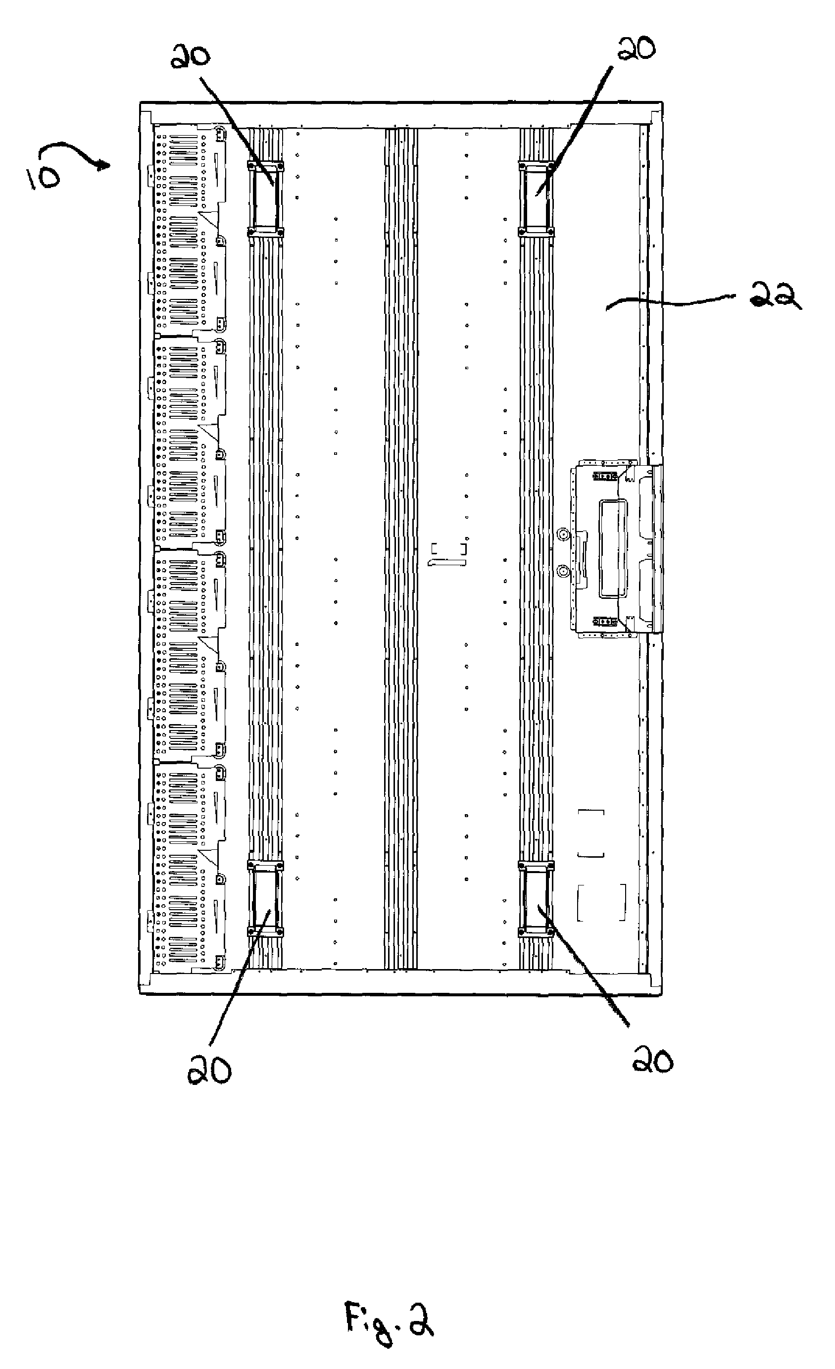
FIG. 2 is a posterior view of a display 10 that may be used in an exemplary embodiment. In a typical display, the display posterior 22 may include four mounting brackets 20. The four mounting brackets 20 are shown by way of example and not by way of limitation, exemplary embodiments may be used with various numbers of mounting brackets 20. The mounting brackets 20 serve to attach the constricted convection plate 30 (shown in FIG. 3) to the display posterior 22. The height that the mounting brackets 20 extending from the display posterior 22 define the depth of the constricted convection cooling channel 50 (shown in FIG. 5). This may also be described as the gap distance between the display posterior 22 and the constricted convection plate.
In an exemplary embodiment, the display posterior 22 may be the posterior surface of a backlight assembly. The backlight assembly may comprise a printed circuit board (PCB) with a plurality of LEDs mounted to the anterior surface. The PCB may have a low level of thermal resistance between the anterior and posterior surfaces such that heat which is generated by the LEDs may be transferred to the posterior surface of the of the backlight assembly, and subsequently removed by air within the constricted convection channel. The PCB may comprise a metal core PCB and the posterior surface of the PCB may be metallic so that air within the constricted convection channel may cool the metallic posterior surface (and subsequently the backlight assembly) more easily and efficiently.
FIG. 3 is an exemplary embodiment of the constricted convection plate 30. The constricted convection plate 30 may have angled side panels 32. The angled side panels 32 are adapted to extend from the constricted convection plate 30 and make contact with the display posterior 22 and direct air through the constricted convection channel 50 (shown in FIG. 5). The constricted convection panel 30 may also be constructed to include access apertures 34. The access apertures 34 are defined by the constricted convection plate 30 and allow access to hardware found on the display posterior 22; without the need to remove the constricted convection plate 30. The access apertures 34 may be plugged before operation to maintain directed contact between the refrigerated air and the posterior display surface 22.
The width of the constricted convection channel 50 may vary according to the thermal requirements of a particular application. In some embodiments, the constricted convection channel 50 may be one-half inch or less. In other embodiments, the constricted convection channel 50 may be between one-half inch and one inch. In still other embodiments, the constricted convection channel 50 may be between one and five inches.
FIG. 4 is an exploded view showing the relationship of a display 10 that may be used in an exemplary embodiment and an exemplary embodiment of the constricted convection plate 30. As described above, the constricted convection plate 30 may be attached to the display posterior 22 by the mounting brackets 20 (shown in FIG. 2). The size of the constricted convection plate 30 may be of sufficient size to cover the entire posterior display surface 22. In other exemplary embodiments, the constricted convection plate 30 may only cover a portion of the posterior display surface 22. Therefore, the size of the constricted convection plate 30 may be adjusted to provide sufficient cooling of the display posterior 22.
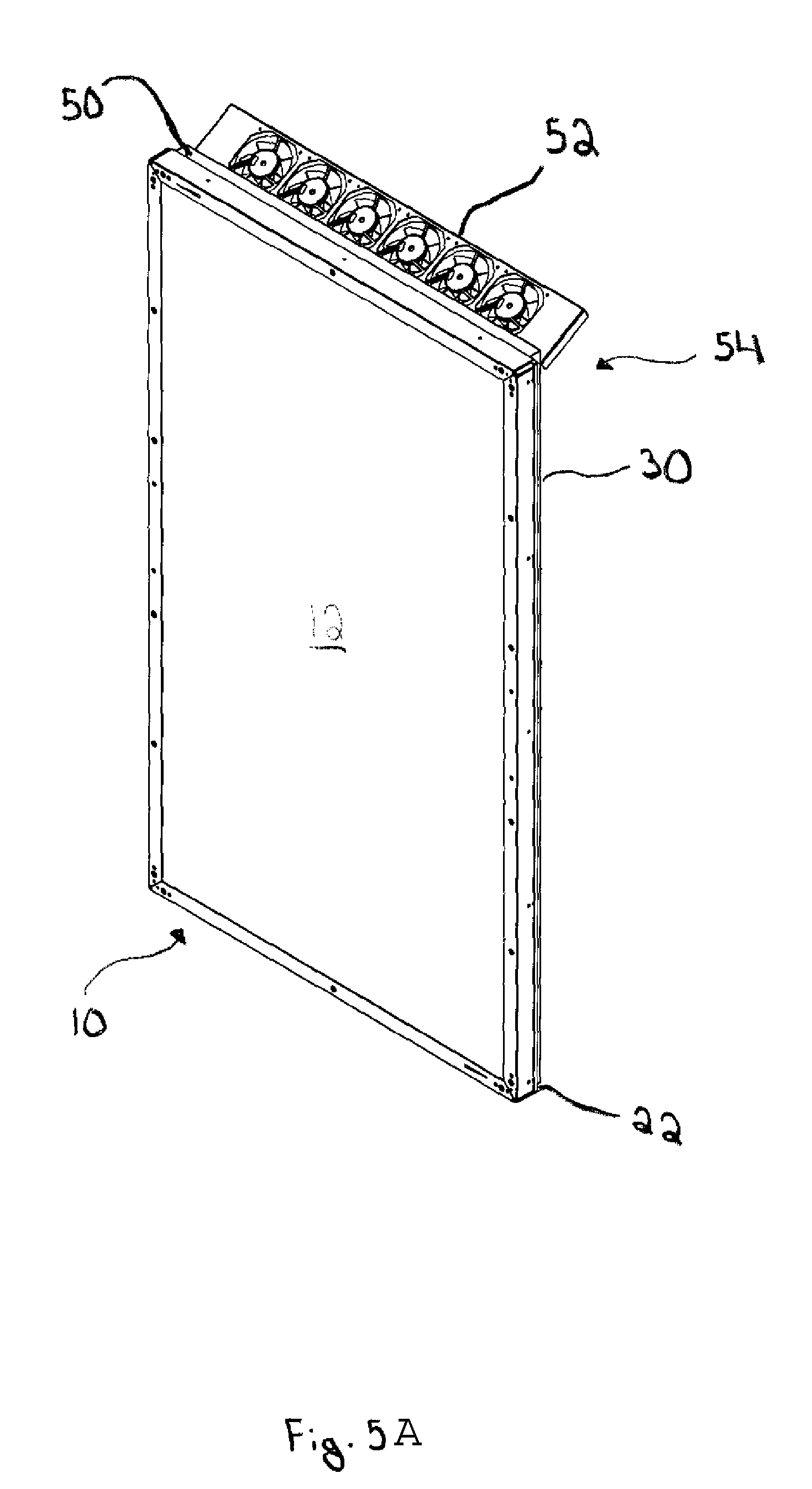
In FIG. 5A, the constricted convection plate 30 is shown mounted to the display posterior 22. The mounting brackets 20 (shown in FIG. 2) may be used to secure the constricted convection plate 30. The constricted convection plate 30 and the display posterior 22 define a constricted convection cooling channel 50 immediately behind the display posterior 22. As discussed above, in some embodiments the constricted convection cooling channel 50 may run the length and width of the display 10. In other embodiments, the constricted convection cooling channel 50 may be only of sufficient size to provide thermal stability to the display 10.
The constricted convection cooling system 54 may include a means for increasing the speed at which air travels through the constricted convection cooling channel 50. This means may include one or more fans 52 which may be positioned near an opening of the constricted convection cooling channel 50. The fans 52 may either force the air through the constricted convection channel 50 or pull the air through the constricted convection channel 50. Alternatively, a plurality of fans may be used to both push and pull air through the constricted convection cooling channel 50. The use of one or more fans 52 may provide increased velocity of the air traveling through the constricted convection cooling channel 50, thus increasing the speed with which heat is transferred from the display posterior 22.
In other exemplary embodiments, a means for cooling the air which passes through the constricted convection cooling channel 50 may be used. A means for cooling the air may include, but is not limited to, a conditioning unit, a refrigeration unit, or any other means to decrease the temperature of the air passing through the constricted convection plate 30. Alternatively, ambient air from the surroundings may be drawn in and forced within the constricted convection channel 50.
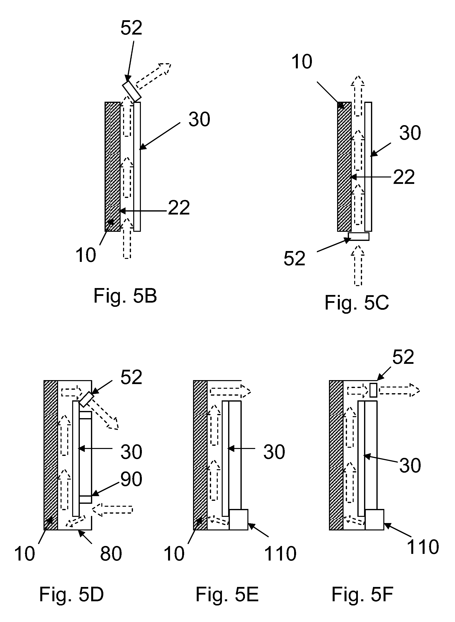
FIGS. 5B through 5F show side views of additional embodiments for the constricted convection system. In FIG. 5B, one or more fans 52 are used to draw ambient air between the posterior display surface 22 and the constricted convection plate 30. In FIG. 5C, one or more fans 52 are used to force ambient air between the posterior display surface 22 and the constricted convection plate 30. FIG. 5D is similar to FIG. 5B except that the housing 80 and the septum 90 are used to direct the flow of air. In FIG. 5E, an air conditioning unit 110 is used to both cool the air and to force the cooled air between the posterior display surface 22 and the constricted convection plate 30. Finally in FIG. 5F, an air conditioning unit 110 is used in combination with one or more fans 52.
FIG. 6 is a double display housing 60 utilizing an exemplary embodiment of the constricted convection air cooling system 54. A constricted convection plate 30 is mounted to a display posterior 22. The constricted convection plate 30 and the display posterior 22 define a constricted convection cooling channel 50 immediately behind the display posterior 22. An entrance opening 62 adapted to receive air is defined by the constricted convection plate 30. An exit opening 64 adapted to expel air from the constricted convection cooling channel 50 is defined by the constricted convection plate 30 and the display posterior 22. As above, the constricted convection plate 30 may have access apertures 34. The access apertures 34 allow access to hardware located behind the constricted convection plate 30. The access apertures 34 may be closed before use using plugs or other similar devices (not shown in the Figures).
An air source (not shown in the Figures) may be in communication with the entrance opening 62. Air is forced through the entrance opening 62 and into the constricted convection channel 50. The constricted convection channel 50 directs the air into contact with the display posterior 22 increasing the heat transfer from the display. After passing over the display posterior 22, the air exits the constricted convection channel 50 through the exit opening 64. The expelled air may then pass through a portion of the double display housing 60 into the atmosphere.
As above, a means for cooling the air (not shown in the Figures) forced into the constricted convection cooling channel 50 may be employed. The means for cooling the air may include, but is not limited to, a conditioning unit, a refrigerating unit, a thermoelectric unit, or any other means to decrease the temperature of the air before entering the constricted convection cooling channel 50.
FIG. 7 is a double display housing 60 that may use an exemplary embodiment of the constricted convection air cooling system 54. The display posterior 22 may include mounting brackets 20. The mounting brackets 20 are shown by way of example and not by way of limitation. The present invention may use various shapes and numbers of mounting brackets 20. The mounting brackets 20 may serve to attach the constricted convection plate 30 (shown in FIG. 3) to the display posterior 22. The height of the mounting brackets 20 extend from the display posterior defines the depth of the constricted convection cooling channel 50 (shown in FIG. 5). Further embodiments may not utilize mounting brackets as they are not necessary to practice the invention.
As with other exemplary embodiments, a means for forcing air within the system and increasing the speed at which the air travels through the constricted convection cooling channel 50 may be used. The means for increasing the air speed may be in association with either the entrance opening 62 or the exit opening 64. The means for increasing the air speed may include, but is not limited to, one or more fans (shown in FIG. 5).
FIG. 8 is an exploded view of another embodiment of the constricted convection cooling system 54. The display 10 may be encased in an external housing 80. The external housing 80 may have an air entrance end 82 and an exhaust end 84. The air entrance end 82 defines an entrance aperture 86. The exhaust end 84 defines an exit aperture 88. The constricted convection plate 30 and the display posterior 22 (not shown in FIG. 8) define a constricted convection cooling channel 50. The constricted convection plate 30 further defines an entrance opening 62 and an exit opening 64. The entrance opening may be adapted to receive air entering the entrance aperture 86. The exit opening may be adapted to expel air through the exit aperture 88.
Septa 90 are associated with the external housing 80. The septa 90 may be adapted to prevent air from evading the constricted convection channel 50. The septa 90 may also be adapted to provide support and an attachment port for the external housing 80.
Air or another appropriate gas may be in gaseous communication with the entrance opening 86. The air then passes through the entrance opening 86 into a middle chamber 92. The middle chamber 92 is defined by the external housing 80 and the constricted convection plate 30. Once the air enters the middle chamber it may be directed through the entrance opening 62. A septum 90 may be positioned to direct air into the entrance opening 62 and prevent the air evading the entrance opening 62. After passing through the entrance opening 62, the air may enter the constricted convection cooling channel 50. As the air passes through the constricted convection cooling channel heat is transferred from the display posterior to the air.
After absorbing heat from the display posterior, the air may exit the constricted convection channel 50 through the exit opening 64. A septum 90 may be used to prevent the exiting air from evading the exit aperture 88, and to direct the air towards the exit aperture 88. The air is then expelled through the exit aperture 88 in to the surrounding atmosphere.
To assist in the movement of air through the constricted convection channel 50, a means to force the air into the channel and increase the air speed may be used. Increasing the air speed and the volumetric flow rate of the air may allow for increased heat removal. The means to increase the air speed may include, but is not limited to, a fan 52. The fan 52 may be associated with the exit opening 64 and may draw air from the constricted convection channel 50. In other embodiments, the fan 52 may be associated with the entrance opening 62 and may force air into the constricted convection channel 50. Other embodiments may utilize a combination of both drawing the air from the channel and forcing the air into the channel. In an exemplary embodiment, a plurality of fans would be distributed across the entire exit opening 64 (or entrance opening 62, or both) in order to produce a uniform flow of air across the posterior display surface to facilitate uniform cooling.
In other exemplary embodiments, a means for cooling air in gas communication with the entrance opening 62 may be employed. The means for cooling the air may include, but is not limited to, a conditioning unit, a refrigerating unit, a thermoelectric unit, or any other device that decreases the temperature of the air. Cooling the air further increases the air's ability to transfer heat from the display posterior 22. The means for cooling air may be housed within the external housing 80, or it may be an external unit.
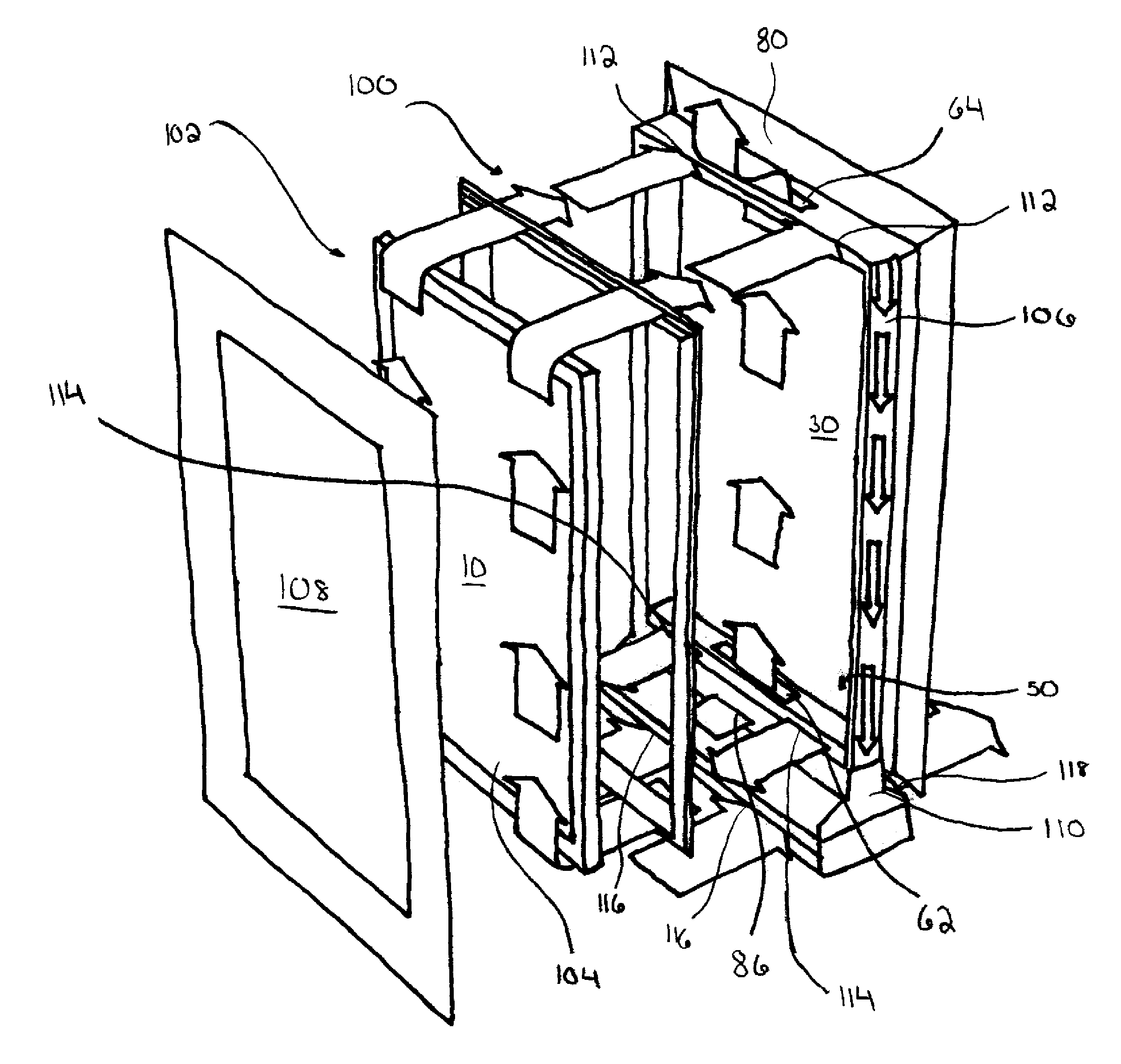
FIG. 9 is a display 10 using and exemplary embodiment of the constricted convection cooling system, where three cooling pathways are used. The first cooling pathway is comprised of the constricted convection plate 30 immediately behind the display posterior. The second cooling pathway is a closed loop and is comprised of the isolated gas cooling system 100. The third cooling pathway is comprised of the ambient air vent system used to cool the refrigeration unit 110. In some embodiments, the first and/or second pathways may include refrigerated air. In still other exemplary embodiments, the first and/or second pathways may contain heated air. The ability to provide cooled and heated air in the pathways allows use of an outdoor electronic display across a variety of climates. Other exemplary embodiments may contain any combination of cooling/heating pathways. For applications which require both heating and cooling, a thermoelectric module may be used as the refrigeration unit 110. Thermoelectric modules are commonly available which can run in both cooling and heating modes.
In the first cooling pathway, a constricted convection plate 30 may be mounted immediately behind the display posterior. A constricted convection channel 50 is defined by the gap between the constricted convection plate 30, and the display posterior.
Air may enter the entrance aperture 86, which is defined by external housing 80. The air passes through the entrance aperture 86 to the entrance opening 62, and into the constricted convection channel 50. The air may then be expelled into the atmosphere from the constricted convection channel 50 through the exit opening 64. Optionally, a means for increasing the speed of the air traveling through the constricted convection channel 50 may be included either associated with the entrance opening 62 or the exit opening 64 or both.
The second cooling pathway may be an exemplary embodiment of an isolated gas cooling system 100. The isolated gas cooling chamber 102 comprises a closed loop which includes a gas chamber 104 and return air passage 106. The gas chamber 104 includes a transparent plate 108. The term "isolated gas" refers to the fact that the gas within the isolated gas cooling chamber 102 is essentially isolated from the external air. In the embodiment shown, the isolated gas cooling system 100 comprises refrigerated air. Because the gas chamber 102 is positioned in front of the display 10, the gas should be substantially free of dust or other contaminates that might negatively affect the display image.
The isolated gas may be almost any transparent gas, including, but not limited to, normal air, nitrogen, helium, or any other transparent gas. The gas is preferably colorless so as not to affect the image quality. Furthermore, the isolated gas cooling chamber 102 need not necessarily be hermetically sealed from the external air. It is sufficient that the gas in the chamber is isolated to the extent that dust and contaminates may not substantially enter the first gas chamber.
The gas chamber 104 is in gaseous communication with the return air passage 106. A refrigeration unit 110 may be provided within the exemplary embodiments. The refrigeration unit may be any device which cools the isolated gas which travels around the isolated gas cooling chamber and sometimes through the constricted convection channel. Along with cooling the air, the refrigeration unit 110 may be utilized to propel the gas around the isolated gas cooling chamber 102 or through the constricted convection channel. The gas chamber 104 includes at least one front glass 108 mounted in front of the display 10. The front glass 108 may be set forward from the display 10 by spacers (not shown in the Figures). The spacing members define the depth of the narrow channel passing in front of the display 10. The spacing members may be independent of alternatively may be integral with some with some other component of the device (i.e., integral with the front plate). The display 10, the spacing members, and the front glass 108 define the narrow gas chamber 104. The gas chamber 104 may be gaseous communication with the return air passage 106 through entrance openings 112 and exit openings 114.
As the isolated gas in the gas chamber 104 traverses the isolated gas cooling chamber 102 it contacts the display 10 surface. Contacting the isolated gas directly to the display 10 allows convective heat transfer from the display 10 to the isolated gas. By utilizing the display 10 as the posterior surface wall of the gas chamber 104, there are fewer surfaces to impact the visible light traveling through the display 10. Furthermore, the device will be lighter and cheaper to manufacture.
Although the embodiment shown utilizes the display 10, certain modifications and/or coatings (e.g., anti-reflective coatings) may be added to the display 10, or to other components of the system in order to accommodate the coolant gas or to improve the optical performance of the device. In the embodiment shown, the display 10 may be the front glass plate of a liquid crystal display (LCD) stack. However, almost any display surface may be suitable for embodiments of the present cooling system. Although not required, it is preferable to allow the cooling gas in the gas chamber 104 to contact the display 10 directly. In this way, the convective effect of the circulating gas will be maximized. Preferably the gas, which has absorbed heat from the display 10 may then be diverted to the refrigeration unit 110 by way of the return air passage 106.
To maintain efficiency of the refrigeration unit 110, a third cooling loop may be utilized, wherein ambient air may be passed through the external housing 80. The ambient air enters the external housing through vent openings 116 and exits through vent exits 118. The ambient air passing through the vent openings 116 and exits 118 carries away heat generated by the refrigeration unit 110.
The refrigeration unit may also cool the air which travels within the constricted convection channel 50. The refrigeration unit may also contain a means to force the cooled air into the constricted convection channel 50. This means may include one or more fans and one or more septa.
An optional air filter (not shown) may be employed within the isolated gas cooling system 100 to assist in preventing contaminates and dust from entering the gas chamber 104. It is also understood that any cooling loop may include cooled air, and as stated above the cooling loop may also provide heated air.
The constricted convection cooling system may also be used in conjunction with an air curtain as described in Co-pending application Ser. No. 11/941,728, hereby incorporated by reference in its entirety.
Having shown and described the preferred embodiments, those skilled in the art will realize that many variations and modifications may be made to affect the described embodiments and still be within the scope of the claimed invention. Additionally, many of the elements indicated above may be altered or replaced by different elements which will provide the same result and fall within the spirit of the claimed invention. It is the intention, therefore, to limit the invention only as indicated by the scope of the claims.
* * * * *
D00000
D00001
D00002
D00003
D00004
D00005
D00006
D00007
D00008
D00009
D00010
XML
uspto.report is an independent third-party trademark research tool that is not affiliated, endorsed, or sponsored by the United States Patent and Trademark Office (USPTO) or any other governmental organization. The information provided by uspto.report is based on publicly available data at the time of writing and is intended for informational purposes only.
While we strive to provide accurate and up-to-date information, we do not guarantee the accuracy, completeness, reliability, or suitability of the information displayed on this site. The use of this site is at your own risk. Any reliance you place on such information is therefore strictly at your own risk.
All official trademark data, including owner information, should be verified by visiting the official USPTO website at www.uspto.gov. This site is not intended to replace professional legal advice and should not be used as a substitute for consulting with a legal professional who is knowledgeable about trademark law.