Point-to-multipoint digital radio frequency transport
Wala Dec
U.S. patent number 10,505,635 [Application Number 15/144,219] was granted by the patent office on 2019-12-10 for point-to-multipoint digital radio frequency transport. This patent grant is currently assigned to CommScope Technologies LLC. The grantee listed for this patent is CommScope Technologies LLC. Invention is credited to Philip M. Wala.


| United States Patent | 10,505,635 |
| Wala | December 10, 2019 |
Point-to-multipoint digital radio frequency transport
Abstract
One embodiment is directed to a system for use with a coverage area in which one or more wireless units wirelessly transmit using a wireless radio frequency spectrum. The system comprises a first unit, and a plurality of second units communicatively coupled to the first unit using at least one communication medium. Each of the plurality of second units generates respective digital RF samples indicative of a respective analog wireless signal received at that second unit. Each of the plurality of second units communicates the respective digital RF samples generated by that second unit to the first unit using the at least one communication medium. The first unit digitally sums corresponding digital RF samples received from the plurality of second units to produce summed digital RF samples. The system is configured so that an input used for base station processing is derived from the resulting summed digital RF samples.
| Inventors: | Wala; Philip M. (Savage, MN) | ||||||||||
|---|---|---|---|---|---|---|---|---|---|---|---|
| Applicant: |
|
||||||||||
| Assignee: | CommScope Technologies LLC
(Hickory, NC) |
||||||||||
| Family ID: | 24481899 | ||||||||||
| Appl. No.: | 15/144,219 | ||||||||||
| Filed: | May 2, 2016 |
Prior Publication Data
| Document Identifier | Publication Date | |
|---|---|---|
| US 20160248508 A1 | Aug 25, 2016 | |
Related U.S. Patent Documents
| Application Number | Filing Date | Patent Number | Issue Date | ||
|---|---|---|---|---|---|
| 14054223 | Oct 15, 2013 | 9332402 | |||
| 13662948 | Nov 5, 2013 | 8577286 | |||
| 12617215 | Dec 4, 2012 | 8326218 | |||
| 10740944 | Dec 29, 2009 | 7639982 | |||
| 09619431 | Mar 9, 2004 | 6704545 | |||
| Current U.S. Class: | 1/1 |
| Current CPC Class: | H04N 19/91 (20141101); H03M 7/4006 (20130101); H04N 19/625 (20141101); H04Q 11/0067 (20130101); H04W 88/08 (20130101); H04B 10/25754 (20130101); H04L 51/28 (20130101); H04W 4/14 (20130101); H04B 7/2606 (20130101); H04N 19/109 (20141101); H04N 19/139 (20141101); H04W 4/06 (20130101); H04W 72/005 (20130101); H04L 51/38 (20130101); H04L 65/1006 (20130101); H04B 10/25753 (20130101); H04B 3/02 (20130101); H04Q 2011/0047 (20130101); H04L 65/1016 (20130101); H04W 88/085 (20130101); Y10S 370/906 (20130101); H04L 51/04 (20130101); H04W 4/12 (20130101); Y10S 370/907 (20130101) |
| Current International Class: | H04B 7/14 (20060101); H04W 4/06 (20090101); H04L 12/58 (20060101); H04W 72/00 (20090101); H04W 4/14 (20090101); H04N 19/139 (20140101); H04N 19/109 (20140101); H04N 19/91 (20140101); H04N 19/625 (20140101); H04Q 11/00 (20060101); H04B 7/26 (20060101); H04B 10/2575 (20130101); H03M 7/40 (20060101); H04W 88/08 (20090101); H04L 29/06 (20060101); H04W 4/12 (20090101) |
| Field of Search: | ;455/14,16,20,561 |
References Cited [Referenced By]
U.S. Patent Documents
| 3931473 | January 1976 | Ferris, Jr. |
| 4101834 | July 1978 | Stutt et al. |
| 4112488 | September 1978 | Smith, III |
| 4144409 | March 1979 | Utano et al. |
| 4144411 | March 1979 | Frenkiel |
| 4183054 | January 1980 | Patisaul et al. |
| 4231116 | October 1980 | Sekiguchi et al. |
| 4244046 | January 1981 | Brouard et al. |
| 4354167 | October 1982 | Terreault et al. |
| 4402076 | August 1983 | Krajewski |
| 4451699 | May 1984 | Gruenberg |
| 4451916 | May 1984 | Casper et al. |
| 4456793 | June 1984 | Baker et al. |
| 4475010 | October 1984 | Huensch et al. |
| 4485486 | November 1984 | Webb et al. |
| 4525861 | June 1985 | Freeburg |
| 4531239 | July 1985 | Usui |
| 4556760 | December 1985 | Goldman |
| 4596051 | June 1986 | Feldman |
| 4611323 | September 1986 | Hessenmuller |
| 4613990 | September 1986 | Halpern |
| 4628501 | December 1986 | Loscoe |
| 4654843 | March 1987 | Roza et al. |
| 4667319 | May 1987 | Chum |
| 4669107 | May 1987 | Eriksson-Lennartsson |
| 4691292 | September 1987 | Rothweiler |
| 4701909 | October 1987 | Kavehrad et al. |
| 4704733 | November 1987 | Kawano |
| 4718004 | January 1988 | Dalal |
| 4726644 | February 1988 | Mathis |
| 4754451 | June 1988 | Eng et al. |
| 4755795 | July 1988 | Page |
| 4759000 | July 1988 | Reitz |
| 4759051 | July 1988 | Han |
| 4759057 | July 1988 | De Luca et al. |
| 4760573 | July 1988 | Calvignac et al. |
| 4790000 | December 1988 | Kinoshita |
| 4797947 | January 1989 | Labedz |
| 4816825 | March 1989 | Chan et al. |
| 4831662 | May 1989 | Kuhn |
| 4849963 | July 1989 | Kawano et al. |
| 4868862 | September 1989 | Ryoichi et al. |
| 4881082 | November 1989 | Graziano |
| 4916460 | April 1990 | Powell |
| 4920533 | April 1990 | Dufresne et al. |
| 4932049 | June 1990 | Lee |
| 4959829 | September 1990 | Griesing |
| 4977593 | December 1990 | Ballance |
| 4999831 | March 1991 | Grace |
| 5067147 | November 1991 | Lee |
| 5067173 | November 1991 | Gordon et al. |
| 5084869 | January 1992 | Russell |
| 5134709 | July 1992 | Bi et al. |
| 5136410 | August 1992 | Heiling et al. |
| 5138440 | August 1992 | Radice |
| 5159479 | October 1992 | Takagi |
| 5175867 | December 1992 | Wejke et al. |
| 5193109 | March 1993 | Chien-Yeh Lee |
| 5243598 | September 1993 | Lee |
| 5251053 | October 1993 | Heidemann |
| 5267261 | November 1993 | Blakeney, II et al. |
| 5272700 | December 1993 | Hansen et al. |
| 5278690 | January 1994 | Vella-Coleiro |
| 5280472 | January 1994 | Gilhousen et al. |
| 5285469 | February 1994 | Vanderpool |
| 5297193 | March 1994 | Bouix et al. |
| 5299198 | March 1994 | Kay et al. |
| 5301056 | April 1994 | O'Neill |
| 5303287 | April 1994 | Laborde |
| 5305308 | April 1994 | English et al. |
| 5309474 | May 1994 | Gilhousen et al. |
| 5313461 | May 1994 | Ahl et al. |
| 5321736 | June 1994 | Beasley |
| 5321849 | June 1994 | Lemson |
| 5339184 | August 1994 | Tang |
| 5381459 | January 1995 | Lappington |
| 5392453 | February 1995 | Gudmundson et al. |
| 5400391 | March 1995 | Emura et al. |
| 5442681 | August 1995 | Kotzin et al. |
| 5442700 | August 1995 | Snell et al. |
| 5457557 | October 1995 | Zarem et al. |
| 5461627 | October 1995 | Rypinski |
| 5499047 | March 1996 | Terry et al. |
| 5513176 | April 1996 | Dean et al. |
| 5519691 | May 1996 | Darcie et al. |
| 5528582 | June 1996 | Bodeep et al. |
| 5533011 | July 1996 | Dean et al. |
| 5546397 | August 1996 | Mahany |
| 5552920 | September 1996 | Glynn |
| 5566168 | October 1996 | Dent |
| 5579341 | November 1996 | Smith et al. |
| 5586121 | December 1996 | Moura et al. |
| 5587734 | December 1996 | Lauder et al. |
| 5592470 | January 1997 | Rudrapatna et al. |
| 5603080 | February 1997 | Kallander et al. |
| 5619202 | April 1997 | Wilson et al. |
| 5621730 | April 1997 | Kelley |
| 5621786 | April 1997 | Fischer et al. |
| 5627879 | May 1997 | Russell |
| 5630204 | May 1997 | Hylton et al. |
| 5642405 | June 1997 | Fischer et al. |
| 5644622 | July 1997 | Russell et al. |
| 5657374 | August 1997 | Russell et al. |
| 5682256 | October 1997 | Motley et al. |
| 5708961 | January 1998 | Hylton et al. |
| 5715235 | February 1998 | Sawahashi et al. |
| 5724385 | March 1998 | Levin et al. |
| 5732076 | March 1998 | Ketseoglou et al. |
| 5748683 | May 1998 | Smith et al. |
| 5752170 | May 1998 | Clifford |
| 5761619 | June 1998 | Danne et al. |
| 5765097 | June 1998 | Dail |
| 5765099 | June 1998 | Georges et al. |
| 5771449 | June 1998 | Blasing et al. |
| 5774085 | June 1998 | Yanagimoto et al. |
| 5774660 | June 1998 | Brendel et al. |
| 5774789 | June 1998 | van der Kaay et al. |
| 5781541 | July 1998 | Schneider |
| 5781859 | July 1998 | Beasley |
| 5781865 | July 1998 | Gammon |
| 5802173 | September 1998 | Hamilton-Piercy et al. |
| 5805983 | September 1998 | Naidu et al. |
| 5809395 | September 1998 | Hamilton-Piercy et al. |
| 5809422 | September 1998 | Raleigh |
| 5809431 | September 1998 | Bustamante et al. |
| 5812605 | September 1998 | Smith et al. |
| 5818883 | October 1998 | Smith et al. |
| 5822324 | October 1998 | Kostresti et al. |
| 5852651 | December 1998 | Fischer et al. |
| 5874914 | February 1999 | Krasner |
| 5878325 | March 1999 | Dail |
| 5907544 | May 1999 | Rypinski |
| 5930682 | July 1999 | Schwartz et al. |
| 5946622 | August 1999 | Bojeryd |
| 5969837 | October 1999 | Farber et al. |
| 5978650 | November 1999 | Fischer et al. |
| 5987014 | November 1999 | Magill et al. |
| 6005506 | December 1999 | Bazarjani et al. |
| 6005884 | December 1999 | Cook et al. |
| 6009130 | December 1999 | Lurey et al. |
| 6014366 | January 2000 | Ichiyoshi |
| 6034950 | March 2000 | Sauer et al. |
| 6061089 | May 2000 | Tonkin et al. |
| 6108113 | August 2000 | Fee |
| 6108550 | August 2000 | Wiorek et al. |
| 6108626 | August 2000 | Cellario et al. |
| 6112086 | August 2000 | Wala |
| 6122529 | September 2000 | Sabat, Jr. et al. |
| 6128470 | October 2000 | Naidu et al. |
| 6128471 | October 2000 | Quelch et al. |
| 6147786 | November 2000 | Pan |
| 6150993 | November 2000 | Dobrovolny |
| 6157659 | December 2000 | Bird |
| 6181687 | January 2001 | Bisdikian |
| 6188693 | February 2001 | Murakami |
| 6192216 | February 2001 | Sabat, Jr. et al. |
| 6198558 | March 2001 | Graves et al. |
| 6222660 | April 2001 | Traa |
| 6223021 | April 2001 | Silvia et al. |
| 6226274 | May 2001 | Reese et al. |
| 6253094 | June 2001 | Schmutz |
| 6259910 | July 2001 | Fairfield et al. |
| 6262981 | July 2001 | Schmutz |
| 6263135 | July 2001 | Wade |
| 6275990 | August 2001 | Dapper et al. |
| 6298246 | October 2001 | Lysejko et al. |
| 6307877 | October 2001 | Philips et al. |
| 6308085 | October 2001 | Shoki |
| 6317884 | November 2001 | Eames et al. |
| 6336042 | January 2002 | Dawson et al. |
| 6337754 | January 2002 | Imajo |
| 6349200 | February 2002 | Sabat, Jr. et al. |
| 6353600 | March 2002 | Schwartz et al. |
| 6356369 | March 2002 | Farhan |
| 6356374 | March 2002 | Farhan |
| 6362908 | March 2002 | Kimbrough et al. |
| 6373611 | April 2002 | Farhan et al. |
| 6373887 | April 2002 | Aiyagari et al. |
| 6374124 | April 2002 | Slabinski |
| 6377640 | April 2002 | Trans |
| 6442405 | August 2002 | Hiramatsu et al. |
| 6449071 | September 2002 | Farhan et al. |
| 6463301 | October 2002 | Bevan et al. |
| 6466572 | October 2002 | Ethridge |
| 6480551 | November 2002 | Ohishi et al. |
| 6480702 | November 2002 | Sabat, Jr. |
| 6486907 | November 2002 | Farber |
| 6498936 | December 2002 | Raith |
| 6504831 | January 2003 | Greenwood et al. |
| 6535720 | March 2003 | Kintis et al. |
| 6567473 | May 2003 | Tzannes |
| 6580905 | June 2003 | Naidu et al. |
| 6594496 | July 2003 | Schwartz |
| 6622013 | September 2003 | Miyoshi et al. |
| 6643498 | November 2003 | Miyajima |
| 6667973 | December 2003 | Gorshe et al. |
| 6674966 | January 2004 | Koonen |
| 6697603 | February 2004 | Lovinggood |
| 6704545 | March 2004 | Wala |
| 6729929 | May 2004 | Sayers et al. |
| 6731904 | May 2004 | Judd |
| 6738581 | May 2004 | Handelman |
| 6745003 | June 2004 | Maca et al. |
| 6751417 | June 2004 | Combs et al. |
| 6768745 | July 2004 | Gorshe et al. |
| 6771933 | August 2004 | Eng et al. |
| 6785558 | August 2004 | Stratford et al. |
| 6799020 | September 2004 | Heidmann et al. |
| 6801767 | October 2004 | Schwartz et al. |
| 6807374 | October 2004 | Imajo et al. |
| 6826163 | November 2004 | Mani et al. |
| 6826164 | November 2004 | Mani et al. |
| 6831901 | December 2004 | Millar |
| 6865390 | March 2005 | Goss et al. |
| 6907048 | June 2005 | Treadaway et al. |
| 6917614 | July 2005 | Laubach et al. |
| 6963552 | November 2005 | Sabat, Jr. et al. |
| 6967966 | November 2005 | Donohue |
| 6980831 | December 2005 | Matsuyoshi et al. |
| 7016308 | March 2006 | Gallagher |
| 7031335 | April 2006 | Donohue et al. |
| 7035671 | April 2006 | Solum |
| 7047313 | May 2006 | Broerman |
| 7075369 | July 2006 | Takenaka |
| 7103279 | September 2006 | Koh et al. |
| 7103377 | September 2006 | Bauman et al. |
| 7127175 | October 2006 | Mani et al. |
| 7171244 | January 2007 | Bauman |
| 7184728 | February 2007 | Solum |
| 7190903 | March 2007 | Combs et al. |
| 7205864 | April 2007 | Schultz, Jr. et al. |
| 7215651 | May 2007 | Millar |
| 7257328 | August 2007 | Levinson et al. |
| 7289972 | October 2007 | Rieser et al. |
| RE40564 | November 2008 | Fischer et al. |
| 7505747 | March 2009 | Solum |
| 7512419 | March 2009 | Solum |
| 7539509 | May 2009 | Bauman et al. |
| 7548695 | June 2009 | Wake |
| 7610046 | October 2009 | Wala |
| 7614074 | November 2009 | Mobley et al. |
| 7639982 | December 2009 | Wala |
| 7702985 | April 2010 | Millar |
| 7761093 | July 2010 | Sabat, Jr. et al. |
| 5627879 | September 2010 | Russell et al. |
| 5657374 | September 2010 | Russell et al. |
| 7848747 | December 2010 | Wala |
| 7848770 | December 2010 | Scheinert |
| 7917177 | March 2011 | Bauman |
| RE40564 | April 2011 | Fischer et al. |
| 7920858 | April 2011 | Sabat, Jr. et al. |
| 7962111 | June 2011 | Solum |
| 8019221 | September 2011 | Zancewicz |
| 8032916 | October 2011 | Oyadomari et al. |
| 8160570 | April 2012 | Sabat, Jr. et al. |
| 8290483 | October 2012 | Sabat, Jr. et al. |
| 8326218 | December 2012 | Wala |
| RE43964 | February 2013 | Fischer et al. |
| 8446530 | May 2013 | Bellers |
| 8559939 | October 2013 | Sabat, Jr. et al. |
| 8577286 | November 2013 | Wala |
| RE45321 | January 2015 | Fischer et al. |
| 8958789 | February 2015 | Bauman et al. |
| 9332402 | May 2016 | Wala |
| 9867052 | January 2018 | Sabat, Jr. et al. |
| 2001/0031014 | October 2001 | Subramanian et al. |
| 2001/0036163 | November 2001 | Sabat, Jr. et al. |
| 2002/0003645 | January 2002 | Kim et al. |
| 2002/0072329 | June 2002 | Bandeira et al. |
| 2002/0167954 | November 2002 | Highsmith et al. |
| 2002/0191565 | December 2002 | Mani et al. |
| 2003/0043928 | March 2003 | Ling et al. |
| 2003/0060178 | March 2003 | Ghassemzadeh et al. |
| 2003/0066087 | April 2003 | Sawyer et al. |
| 2003/0133182 | July 2003 | Ng et al. |
| 2003/0143947 | July 2003 | Lyu |
| 2003/0157943 | August 2003 | Sabat, Jr. |
| 2003/0162516 | August 2003 | Solum |
| 2004/0010609 | January 2004 | Vilander et al. |
| 2004/0037565 | February 2004 | Young et al. |
| 2004/0198453 | October 2004 | Cutrer et al. |
| 2004/0219950 | November 2004 | Pallonen et al. |
| 2005/0007993 | January 2005 | Chambers et al. |
| 2005/0131645 | June 2005 | Panopoulos |
| 2005/0147067 | July 2005 | Mani et al. |
| 2005/0201323 | September 2005 | Mani et al. |
| 2005/0243785 | November 2005 | Sabat, Jr. et al. |
| 2005/0250503 | November 2005 | Cutrer |
| 2006/0121944 | June 2006 | Buscaglia et al. |
| 2006/0193295 | August 2006 | White et al. |
| 2007/0166036 | July 2007 | Combs et al. |
| 2009/0034979 | February 2009 | Zancewicz |
| 2009/0067841 | March 2009 | Combs et al. |
| 2010/0061291 | March 2010 | Wala |
| 2011/0182583 | July 2011 | Rakib |
| 2011/0265140 | October 2011 | Rakib |
| 2014/0016583 | January 2014 | Smith |
| 2016/0056874 | February 2016 | Wala |
| 2017/0214460 | July 2017 | Wala |
| 2018/0115910 | April 2018 | Sabat, Jr. et al. |
| 2018/0278299 | September 2018 | Morrison |
| 2008900 | Jan 1998 | CA | |||
| 1127056 | Jul 1996 | CN | |||
| 1362799 | Aug 2002 | CN | |||
| 3707244 | Sep 1988 | DE | |||
| 0166885 | Jan 1986 | EP | |||
| 0368673 | May 1990 | EP | |||
| 0391597 | Oct 1990 | EP | |||
| 0468688 | Jan 1992 | EP | |||
| 0642243 | Mar 1995 | EP | |||
| 0346925 | Apr 1995 | EP | |||
| 0664621 | Jul 1995 | EP | |||
| 0664621 | Jul 1995 | EP | |||
| 0876073 | Nov 1998 | EP | |||
| 2290850 | Mar 2011 | EP | |||
| 1303929 | Oct 2011 | EP | |||
| 1570626 | Nov 2013 | EP | |||
| 3035562 | Jun 2016 | EP | |||
| 2345865 | Oct 1977 | FR | |||
| 2253770 | Sep 1992 | GB | |||
| 2289198 | Nov 1995 | GB | |||
| 2300549 | Nov 1996 | GB | |||
| 2315959 | Feb 1998 | GB | |||
| 2320653 | Jun 1998 | GB | |||
| 540424 | Mar 1956 | IT | |||
| 58164007 | Sep 1983 | JP | |||
| 3026031 | Feb 1991 | JP | |||
| 512374 | Jan 1993 | JP | |||
| H05153021 | Jun 1993 | JP | |||
| H05268128 | Oct 1993 | JP | |||
| 6318905 | Nov 1994 | JP | |||
| 8510878 | Nov 1996 | JP | |||
| 11234200 | Aug 1999 | JP | |||
| 2002354534 | Dec 2002 | JP | |||
| 100594770 | Jun 2006 | KR | |||
| 9115927 | Oct 1991 | WO | |||
| 9128690 | Dec 1994 | WO | |||
| 9533350 | Dec 1995 | WO | |||
| 9628946 | Sep 1996 | WO | |||
| 9705704 | Feb 1997 | WO | |||
| 9716000 | May 1997 | WO | |||
| 9732442 | Sep 1997 | WO | |||
| 9824256 | Jun 1998 | WO | |||
| 9837715 | Aug 1998 | WO | |||
| 9937035 | Jul 1999 | WO | |||
| 9948312 | Sep 1999 | WO | |||
| 0021221 | Apr 2000 | WO | |||
| 0174013 | Jan 2001 | WO | |||
| 0156197 | Aug 2001 | WO | |||
| 0174100 | Oct 2001 | WO | |||
| 0209319 | Jan 2002 | WO | |||
| 0209319 | Jan 2002 | WO | |||
| 0239624 | May 2002 | WO | |||
| 2004051322 | Jun 2004 | WO | |||
Other References
|
Brazilian Patent Office, "Office Action for Brazil Application No. PI0112653-9", "from Foreign Countpart to U.S. Appl. No. 09/619,431", Apr. 8, 2015, pp. 1-14, Published in: BR. cited by applicant . Chinese Patent Office, "Office Action", "from Foreign Counterpart of U.S. Appl. No. 09/619,431", Jul. 8, 2005, pp. 1-8, Published in: CN. cited by applicant . Chinese Patent Office, "Office Action", "from Foreign Counterpart of U.S. Appl. No. 09/619,431", May 11, 2007, pp. 1-5, Published in: CN. cited by applicant . Chinese Patent Office, "Office Action", "from Foreign Counterpart of U.S. Appl. No. 09/619,431", Oct. 26, 2007, pp. 1-3, Published in: CN. cited by applicant . Chinese Patent Office, "Office Action", "from Foreign Counterpart of U.S. Appl. No. 09/619,431", Mar. 7, 2007, pp. 1-8, Published in: CN. cited by applicant . Chinese Patent Office, "Notification to Grant Patent Right for Invention", "from Foreign Counterpart of U.S. Appl. No. 09/619,431", May 28, 2013, pp. 1-3, Published in: CN. cited by applicant . Chinese Patent Office, "Office Action", "from Foreign Counterpart of U.S. Appl. No. 09/619,431", Feb. 4, 2013, pp. 1-7, Published in: CN. cited by applicant . Chinese Patent Office, "Office Action", "from Foreign Counterpart of U.S. Appl. No. 09/619,431", Mar. 19, 2010, pp. 1-7, Published in: CN. cited by applicant . Chinese Patent Office, "Office Action", "from Foreign Counterpart of U.S. Appl. No. 09/619,431", Nov. 2, 2010, pp. 1-9, Published in: CN. cited by applicant . Chinese Patent Office, "Office Action", "from Foreign Counterpart of U.S. Appl. No. 09/619,431", May 21, 2012, pp. 1-18, Published in: CN. cited by applicant . Chinese Patent Office, "Office Action", "from Foreign Counterpart of U.S. Appl. No. 09/619,431", Jan. 23, 2013, pp. 1-11, Published in: CN. cited by applicant . Chinese Patent Office, "Office Action", "from Foreign Counterpart of U.S. Appl. No. 09/619,431", Apr. 6, 2012, pp. 1-12, Published in: CN. cited by applicant . European Patent Office, "Communication under Rule 71(3) EPC", "from Foreign Counterpart of U.S. Appl. No. 09/619,431", May 3, 2011, pp. 1-5, Published in: EP. cited by applicant . European Patent Office, "Office Action", "from Foreign Counterpart of U.S. Appl. No. 09/619,431", Feb. 24, 2006, pp. 1-5, Published in: EP. cited by applicant . European Patent Office, "Office Action", "from Foreign Counterpart of U.S. Appl. No. 09/619,431", Mar. 6, 2007, pp. 1-4, Published in: EP. cited by applicant . European Patent Office, "Office Action", "from Foreign Counterpart of U.S. Appl. No. 09/619,431", Nov. 16, 2010, pp. 1-4, Published in: EP. cited by applicant . European Patent Office, "Summons to Attend Oral Proceedings", "from Foreign Counterpart of U.S. Appl. No. 09/619,431", May 21, 2010, pp. 1-6, Published in: EP. cited by applicant . European Patent Office, "Extended European Search Report", "from Foreign Counterpart of U.S. Appl. No. 09/619,431", Jan. 14, 2011, pp. 1-9, Published in: EP. cited by applicant . European Patent Office, "Communication under Rule 71(3) from European Application Serial No. 10011450.3", "from Foreign Counterpart to U.S. Pat. No. 6,704,545", Jul. 14, 2015, pp. 1-39, Published in: EP. cited by applicant . European Patent Office, "European Office Action for Application Serial No. 10011450.3", "from Foreign Counterpart of U.S. Appl. No. 09/619,431", Jan. 16, 2015, pp. 1-4, Published in: EP. cited by applicant . U.S. Patent Office, "Notice of Allowance", "U.S. Appl. No. 09/619,431", Aug. 12, 2003, pp. 1-9. cited by applicant . U.S. Patent and Trademark Office, "Office Action", "U.S. Appl. No. 09/619,431", Mar. 13, 2003, pp. 1-15. cited by applicant . U.S. Patent and Trademark Office, "Final Office Action", "U.S. Appl. No. 10/740,944", Apr. 25, 2007, pp. 1-19. cited by applicant . U.S. Patent and Trademark Office, "Final Office Action", "U.S. Appl. No. 10/740,944", Jul. 18, 2007, pp. 1-21. cited by applicant . U.S. Patent and Trademark Office, "Final Office Action", "U.S. Appl. No. 10/740,944", Oct. 3, 2007, pp. 1-22. cited by applicant . U.S. Patent and Trademark Office, "Final Office Action", "U.S. Appl. No. 10/740,944", Oct. 14, 2008, pp. 1-25. cited by applicant . U.S. Patent and Trademark Office, "Notice of Allowance", "U.S. Appl. No. 10/740,944", Aug. 13, 2009, pp. 1-12. cited by applicant . U.S. Patent and Trademark Office, "Office Action", "U.S. Appl. No. 10/740,944", Aug. 24, 2006, pp. 1-19. cited by applicant . U.S. Patent and Trademark Office, "Final Office Action", "U.S. Appl. No. 10/740,944", Feb. 5, 2007, pp. 1-16. cited by applicant . U.S. Patent and Trademark Office, "Office Action", "U.S. Appl. No. 10/740,944", Apr. 3, 2008. cited by applicant . U.S. Patent and Trademark Office, "Office Action", "U.S. Appl. No. 10/740,944", Feb. 27, 2009, pp. 1-25. cited by applicant . U.S. Patent and Trademark Office, "Notice of Allowance", "U.S. Appl. No. 12/617,215", Aug. 2, 2012, pp. 1-11. cited by applicant . U.S. Patent and Trademark Office, "Office Action", "U.S. Appl. No. 12/617,215", Apr. 11, 2012, pp. 1-12. cited by applicant . U.S. Patent and Trademark Office, "Notice of Allowance and Fees Due", "from U.S. Appl. No. 13/662,948", Jul. 3, 2013, pp. 1-10, Published in: US. cited by applicant . U.S. Patent and Trademark Office, "Office Action", "from U.S. Appl. No. 13/662,948", Apr. 24, 2013, pp. 1-23, Published in: US. cited by applicant . U.S. Patent Office, "Notice of Allowance", "from U.S. Appl. No. 14/054,223", Aug. 14, 2015, pp. 1-5, Published in: US. cited by applicant . U.S. Patent Office, "Notice of Allowance", "from U.S. Appl. No. 14/054,223", Dec. 22, 2015, pp. 1-9, Published in: US. cited by applicant . U.S. Patent Office, "Supplemental Notice of Allowability and Response to Rule 312 Communication", "from U.S. Appl. No. 14/054,223", Apr. 11, 2016, pp. 1-4, Published in: US. cited by applicant . U.S. Patent Office, "Office Action", "from U.S. Appl. No. 14/054,223", Apr. 29, 2015, pp. 1-25, Published in: US. cited by applicant . International Searching Authority, "International Search Report", "from Foreign Counterpart of U.S. Appl. No. 09/619,431", Nov. 15, 2001, pp. 1-7, Published in: WO. cited by applicant . Akos et al, "Direct Bandpass Sampling of Multiple Distinct RF Signals", Jul. 1, 1999, pp. 983-988, vol. 47, Publisher: IEEE Transactions on Communications. cited by applicant . Foxcom Wireless Properietary Information, "Litenna In-Building RF Distribution System", 1998, pp. 1-8. cited by applicant . 1998 Foxcom Wireless Proprietary Information, "Application Note "RFiber--RF Fiberoptic Links for Wireless Applications"", 1998, pp. 3-11, Published in: US. cited by applicant . Grace, Martin K., "Synchronous Quantized Subcarrier Multiplexing for Transport of Video, Voice and Data", "IEEE Journal on Selected Areas in Communications", Sep. 1990, pp. 1351-1358, vol. 8, No. 7, Publisher: IEEE. cited by applicant . Harvey et al., "Cordless Communications Utilising Radio Over Fibre Techniques for the Local Loop", "IEEE ntemational Conference on Communications", Jun. 1991, pp. 1171-1175, Publisher: IEEE. cited by applicant . Nakatsugawa et al., "Software Radio Base and Personal Stations for Cellular/PCS Systems", 2000, pp. 617-621, Publisher: IEEE, date 2000. cited by applicant . European Patent Office, "Reissued Communication under Rule 71(3) from European Application Serial No. 10011450.3", "from Foreign Counterpart to U.S. Pat. No. 6,704,545", Jan. 26, 2016, pp. 137, Published in: EP. cited by applicant . Brazil Patent Office, "Office Action for Brazil Application No. PI0112653-9", "from Foreign Counterpart to U.S. Appl. No. 09/619,431", Jan. 8, 2016, pp. 1-7, Published in: BR. cited by applicant . European Patent Office, "Extended European Search Report for EP Application No. 15020262.0", "from Foreign Counterpart to U.S. Appl. No. 09/619,431", May 20, 2016, pp. 1-8, Published in: EP. cited by applicant . U.S. Patent Office, "Notice of Allowance", "from U.S. Appl. No. 14/054,223", Dec. 22, 2015, No. 1-9, Published in: US. cited by applicant . Wala, "A New Microcell Architecture Using Digital Optical Transport", "Freedom Through Wireless Technogolgy", May 18, 1993, pp. 585-588, Publisher: Proceedings of the Vehicular Technology Conference, New York, IEEE, Published in: US. cited by applicant . ADC Kentrox, "CityCell 824, Remote-Site Manual: Preliminary Version", Feb. 1, 1993, pp. 1-105, Publisher: ADC Kentrox. cited by applicant . Analog Devices, Inc., "Mixed-Signal Design Seminar", 1991, pp. 1-3, Publisher: Analog Devices, Inc. cited by applicant . Brunner et al, "On Space-Time Rake Receiver Structures for WCDMA", Oct. 1999, pp. 1546-1551, Publisher: IEEE. cited by applicant . Cheun, "Performance of Direct-Sequence Spread-Spectrum RAKE Receivers with Random Spreading Sequences", "IEEE Transactions on Communications", Sep. 1997, pp. 1130-1143, vol. 45, No. 9, Publisher: IEEE. cited by applicant . "Dali Wireless, Inc.'s Preliminary Invalidity Contentions to Commscope Technoliges LLC", "Commscope Technologies LLC v. Dali Wireless, Inc. v. Commscope Connectivity LLC", No. 3:16-cv-477, "United States District Court for the Northern District of Texas Dallas Division", Mar. 13, 2017, pp. 1-23, Published in: US. cited by applicant . "Dali Wireless, Inc.'s Preliminary Invalidity Contentions to Commscope Technoliges LLC--Exhibit A", "Commscope Technologies LLC v. Dali Wireless, Inc. v. Commscope Connectivity LLC", No. 3:16-cv-477, "United States District Court for the Northern District of Texas Dallas Division", Mar. 13, 2017, pp. 1-27, Published in: US. cited by applicant . "Dali Wireless, Inc.'s Preliminary Invalidity Contentions to Commscope Technoliges LLC--Exhibit B", "Commscope Technologies LLC v. Dali Wireless, Inc. v. Commscope Connectivity LLC", No. 3:16-cv-477, "United States District Court for the Northern District of Texas Dallas Division", Mar. 13, 2017, pp. 1-200, Published in: US. cited by applicant . "Dali Wireless, Inc.'s Preliminary Invalidity Contentions to Commscope Technoliges LLC--Exhibit C", "Commscope Technologies LLC v. Dali Wireless, Inc. v. Commscope Connectivity LLC", No. 3:16-cv-477, "United States District Court for the Northern District of Texas Dallas Division", Mar. 13, 2017, pp. 1-410, Published in: US. cited by applicant . "Dali Wireless, Inc.'s Preliminary Invalidity Contentions to Commscope Technoliges LLC--Exhibit D", "Commscope Technologies LLC v. Dali Wireless, Inc. v. Commscope Connectivity LLC", No. 3:16-cv-477, "United States District Court for the Northern District of Texas Dallas Division", Mar. 13, 2017, pp. 1-613, Published in: US. cited by applicant . "Dali Wireless, Inc.'s Preliminary Invalidity Contentions to Commscope Technoliges LLC--Exhibit E", "Commscope Technologies LLC v. Dali Wireless, Inc. v. Commscope Connectivity LLC", No. 3:16-cv-477, "United States District Court for the Northern District of Texas Dallas Division", Mar. 13, 2017, pp. 1-482, Published in: US. cited by applicant . "Dali Wireless, Inc.'s Preliminary Invalidity Contentions to Commscope Technoliges LLC--Exhibit F", "Commscope Technologies LLC v. Dali Wireless, Inc. v. Commscope Connectivity LLC", No. 3:16-cv-477, "United States District Court for the Northern District of Texas Dallas Division", Mar. 13, 2017, pp. 1-573, Published in: US. cited by applicant . Crofut, "Remote Monitoring of Wireless Base Stations", "http://urgentcomm.com/print/mag/remote-monitoring-wireless-base-stations- ", Jun. 1, 1998, pp. 1-4. cited by applicant . Cyr et al., "The Digital Age is Here--Digital Radio Frequency Transport Enhances Cellular Network Performance", "Telephony", Jul. 5, 1993, pp. 20-24. cited by applicant . Graf, "Modern Dictionary of Electronics--Seventh Edition", 1999, pp. 1-9. cited by applicant . Grundmann et al., "An Empirical Comparison of a Distributed Antenna Microcell System Versus a Single Antenna Microcell System for Indoor Spread Spectrum Communications at 1.8 GHz", "ICUPC '93", Oct. 1993, pp. 59-63, Publisher: IEEE. cited by applicant . Zhaohui et al., "A RAKE Type Receiver Structure for CDMA Mobile Communication Systems Using Antenna Arrays", Jun. 1996, pp. 528-530, Publisher: IEEE. cited by applicant . "Photographs of ADC Kentrox City Cell 824 Components; Publication Date Unknown", pp. 1-14. cited by applicant . "ADC Telecommunications, Inc.", "Widen Your Horizons", 1994, pp. 1-8, Publisher: ADC Telecommunications, Inc. cited by applicant . "CityCell 824 Host-Site User Manual", Sep. 25, 1993, pp. 1-108. cited by applicant . ADC Kentrox, "ADC Kentrox Expands RF Technology Base with Acquisition of Waseca Technology Inc.", "ADC Kentrox New Release", Jun. 9, 1993, pp. 1-2, Publisher: ADC Kentrox. cited by applicant . Horowitz, "Digital Electronics", "Chapter 8", Pages 2, 1980, Publisher: Cambridge University Press. cited by applicant . Siala et al., "Equalization for Orthogonal Frequency Division Multiplexing System", 1993, pp. 649-652, Publisher: IEEE. cited by applicant . U.S. Patent and Trademark Office, Office Action, dated Oct. 11, 2017, from U.S. Appl. No. 15/483,432, pp. 1-15, US. cited by applicant . U.S. Patent and Trademark Office, "Office Action", U.S. Appl. No. 10/395,743, dated Jan. 14, 2010, pp. 1-31, Published: US. cited by applicant . U.S. Patent and Trademark Office, "Office Action", U.S. Appl. No. 10/395,743, dated Jan. 30, 2006, pp. 1-15, Published: US. cited by applicant . U.S. Patent and Trademark Office, "Office Action", U.S. Appl. No. 10/395,743, dated Nov. 15, 2007, pp. 1-16, Published: US. cited by applicant . U.S. Patent and Trademark Office, "Office Action", U.S. Appl. No. 10/395,743, dated Mar. 28, 2005, pp. 1-11, Published: US. cited by applicant . U.S. Patent and Trademark Office, "Office Action", U.S. Appl. No. 10/395,743, dated Apr. 4, 2007, pp. 1-11, Published: US. cited by applicant . U.S. Patent and Trademark Office, "Office Action", U.S. Appl. No. 10/395,743, dated May 21, 2008, pp. 1-14, Published: US. cited by applicant . U.S. Patent and Trademark Office, "Office Action", U.S. Appl. No. 10/395,743, dated Sep. 1, 2006, pp. 1-12, Published: US. cited by applicant . "And Now a Few Words From Your Customers . . . ", Aug. 1, 1992, pp. 1-4, Publisher: ADC Kentrox. cited by applicant . ADC Kentrox, "First Field Trial Results Exceeded Expectations ADC Kentrox and Cellular One Join Force to Provide a New Level of Portable Service", Mar. 2, 1993, pp. 1-2, Publisher: ADC Kentrox. cited by applicant . ADC Kentrox, "ADC Kentrox Introduces Citycell 824, A Replacement for Conventional Cell Sites; Company's Original Goal Was to Improve Fiber Optic T1 Links Between Cells, MTSOs", "Telocator Bulletin", Feb. 1993, p. 1, Publisher: CityCell. cited by applicant . ADC Kentrox, "Wireless Systems Group Citycell 824--A Positioning White Paper", Mar. 1993, pp. 1-6, Publisher: Cita Trade Show. cited by applicant . Anaren, "Anaren Microwave Components", pp. 1-2. cited by applicant . Anon, "2 GHz Repeater Built Without I-F", "Microwaves", Jun. 1976, pp. 1-2, vol. 15, No. 6, p. 16, Publisher: Hayden Publishing Company Inc. cited by applicant . Cellular Industry, "ADC Kentrox Citycell Field Trial Yields Another First--Simultaneous Analog and Digital Calls", "City Cell", Dec. 22, 2000, p. 1. cited by applicant . Cox, "A Radio System Proposal for Widespread Low-Power Tetherless Communications", IEEE Transactions on Communications, May 1991, pp. 1-29, vol. 39, No. 2, IEEE. cited by applicant . Ericksson, "Advertisement by Ericksson", "Telephony", 1994, p. 1. cited by applicant . European Patent Office, "Communication pursuant to Article 94(3) from EP Application No. 03790242.6 dated Feb. 11, 2009", from Foreign Counterpart to PCT Application No. PCT/US03/38302, Feb. 11, 2009, pp. 1-4, Published: EP. cited by applicant . European Patent Office, "Communication under Rule 71(3) from EP Application No. 10011450.3 dated Aug. 11, 2015", from Foreign Counterpart to U.S. Appl. No. 09/619,431, Aug. 11, 2015 , pp. 1-40, Published: EP. cited by applicant . Ameritech, "Broadband Optical Transport Digital Microcell Connection Service--Interface and Performance Specifications", Dec. 1993, p. Cover--26, No. 1, Publisher: Ameritech. cited by applicant . GTE Laboratories, "Urban Microcell System Layout", "GTE Laboratories Conference", Jun. 14-18, 1992, pp. 1-13, Published in: US. cited by applicant . Gupta et al., "Land Mobile Radio Systems--A Tutorial Exposition", Jun. 1985, pp. 33-45, vol. 23, No. 6, Publisher IEEE Communications Magazine. cited by applicant . IEE, "Electronics Letters an International Publication", Nov. 19, 1987, pp. 1-4, vol. 23, No. 24, Publisher: The Institution of Electrical Engineers. cited by applicant . International Preliminary Examining Authority, "Notification of Transmittal of International Preliminary Examination Report from PCT Application No. PCT/US01/21021 dated Oct. 6, 2002", from Foreign Counterpart to U.S. Appl. No. 09/619,431, Oct. 6, 2002, pp. 1-3, Published: EP. cited by applicant . International Preliminary Examining Authority, "Notification of Transmittal of International Preliminary Report on Patentability from PCT Application No. PCT/US03/38302 dated Dec. 14, 2011", from Foreign Counterpart to U.S. Appl. No. 10/395,743, Dec. 14, 2011, pp. 1-10, Published: IPEA/US. cited by applicant . International Preliminary Examining Authority, "Written Opinion from PCT Application No. PCT/US01/21021 dated Mar. 18, 2002", from Foreign Counterpart to U.S. Appl. No. 09/619,431, Mar. 18, 2002, pp. 1-2, Published: EP. cited by applicant . International Searching Authority, "Notification of Transmittal of the International Search Report from PCT Application No. PCT/US03/38302 dated May 2, 2005", from Foreign Counterpart to U.S. Appl. No. 10/395,743, May 2, 2005, pp. 1-5, Published: ISA/US. cited by applicant . Ishio et al., "A Two-Way Wavelength-Division-Multiplexing Transmission and Its Application to a Switched TV Distribution System", "Conference Record, Fourth European Conference on Optical Communication", Sep. 12, 1978, pp. 645-665, Publisher: IIC. cited by applicant . Kobb, "Personal Wireless", Spectrum, Jun. 1993, pp. 1-8, vol. 30, No. 6, Publisher: IEEE, Published in: US. cited by applicant . Korean Intellectual Property Office, "Decision to Grant from KR Application No. 2005-7010190 dated Feb. 2, 2012", from Foreign Counterpart to PCT Application No. PCT/US03/38302, Feb. 2, 2012, pp. 1-7, Published: KR. cited by applicant . Korean Intellectual Property Office, "Notice of Final Rejection from KR Application No. 10-2005-7010190 dated Oct. 31, 2011", from Foreign Counterpart to PCT Application No. PCT/US03/38302, Oct. 31, 2011, pp. 1-4, Published: KR. cited by applicant . Korean Intellectual Property Office, "Office Action from KR Application No. 2005-7010190 dated Sep. 30, 2010,", from Foreign Counterpart to PCT Application No. PCT/US03/38302, Sep. 30, 2010, pp. 1-5, Published: KR. cited by applicant . Lee et al., "Intelligent Microcell Applications in PCS", "Vehicular Technology Conference, 1993., 43rd IEEE", May 20, 1993, pp. 721-727, Publisher: IEEE. cited by applicant . Lewis, "ADC-Kentrox Call Report With Bell Atlantic", Oct. 18, 1992, pp. 1-3. cited by applicant . Merrett et al., "A Cordless Access System Using Radio-Over-Fibre Techniques", "Gateway to the Future Technology in Motion", May 22, 1991, pp. Cover--924, Publisher: 41st IEEE Vehicular Technology Conference. cited by applicant . Microwaves & RF, "Digital Transport for Cellular", Feb. 1993, p. 1. cited by applicant . Oades, "The Linear RF Repeater", "1980 International Conference on Communications", Jun. 8-12, 1980, p. 1, Publisher: IEEE. cited by applicant . O'Byrne, "TDMA and CDMA in a Fiber-Optic Environment", "Vehicular Technology Conference, 1988, IEEE 38th", Jun. 1992, pp. 727-731, Publisher: IEEE1-5, IEEE. cited by applicant . Patent Office, P.R. China, "Office Action from CN Application No. 200380109396.3 dated Jan. 4, 2008", from Foreign Counterpart to PCT Application No. PCT/US03/38302, Jan. 4, 2008, pp. 1-7, Published: CN. cited by applicant . Payne et al., "Single Mode Optical Local Networks", "Globecom '85", Dec. 5, 1985, pp. 1200-1206, Publisher: IEEE Global Telecommunications Conference. cited by applicant . Quinn, "The Cell Enhancer", "Vehicular Technology Conference", May 22, 1986, pp. 77-83, Publisher: Bell Atlantic Mobile Systems. cited by applicant . Rosenbloom et al., "Cell Enhancer: Beyond the Outer Limits", pp. 1-2. cited by applicant . Russell, "New Microcell Technology Sets Cellular Carriers Free", "Telephony Mar. 1993", pp. 40-42, Publisher: ADC Kentrox, Published in: US. cited by applicant . Zonemaster, "Maximum Coverage for High-Capacity Locations", "Decibel Products", 1993, pp. 1-4, Publisher: Decibel Multi Media Microcell System. cited by applicant . Schneiderman, "Offshore Markets Gain in Size, Competitiveness Even the Smallest Industry Companies are Expanding Their Global Buisness", "Microwaves and RF", Mar. 1993, pp. 33-39, vol. 32, No. 3, Publisher: Penton Publishing, Inc. cited by applicant . State Intellectual Property Office, P.R. China, "Notification to Grant Patent Right for Invention from CN Application No. 200380109396.3 dated Jun. 29, 2010", from Foreign Counterpart to PCT Application No. PCT/US03/38302, Jun. 29, 2010, pp. 1-4, Published: CN. cited by applicant . State Intellectual Property Office, P.R. China, "Notification to Grant Patent Right for Invention from CN Application No. 200910005002.9 dated Aug. 19, 2013", from Foreign Counterpart to U.S. Appl. No. 09/619,431, Aug. 19, 2013, pp. 1-6, Published: CN. cited by applicant . Steele, "Towards a High-Capacity Digital Cellular Mobile Radio System", "Special Issue on Land Mobile Radio", Aug. 1985, pp. 405-415, vol. 132, Number Pt. F, No. 5, Publisher: IEEE Proceedings. cited by applicant . Tang, "Fiber Optic Antenna Remoting for Multi-Sector Cellular Cell Sites", GTE Laboratories, at least as early as Jul. 9, 1993, pp. 1-22. cited by applicant . Tang, "Fiber-Optic Antenna Remoting for MultiSector Cellular Cell Sites", Jan. 1, 1992, pp. 76-81, Publisher: GTE Laboratories. cited by applicant . Tektronix, "Synchronous Optical Network (SONET)", "http://www.iec.org/online/tutorials/sonet/topic03.html", Aug. 28, 2002, pp. 1-5, Publisher: International Engineering Consortium. cited by applicant . The Day Group, "New Signal Transport Technology Digitizes the Cellular Band", "Cellular Industry", , pp. 1-2, Publisher: City Cell. cited by applicant . Titch, "Kentrox Boosts Coverage and Capacity", "Telephony", Jan. 25, 1993, pp. 11-12. cited by applicant . U.S. Patent and Trademark Office, "Final Office Action", U.S. Appl. No. 10/395,743, dated Jul. 21, 2010, pp. 1-23, Published: US. cited by applicant . U.S. Patent and Trademark Office, "Final Office Action", U.S. Appl. No. 10/395,743, dated Nov. 17, 2008, pp. 1-15, Published: US. cited by applicant . U.S. Patent and Trademark Office, "Final Office Action", U.S. Appl. No. 10/395,743, dated Aug. 20, 2009, pp. 1-22, Published: US. cited by applicant . U.S. Patent and Trademark Office, "Notice of Allowance", U.S. Appl. No. 10/395,743, dated Jun. 4, 2014, pp. 1-5, Published: US. cited by applicant . U.S. Patent and Trademark Office, "Notice of Allowance", U.S. Appl. No. 10/395,743, dated Sep. 12, 2014, pp. 1-25, Published: US. cited by applicant . U.S. Patent and Trademark Office, "Office Action", U.S. Appl. No. 15/483,432, dated Dec. 17, 2018, pp. 1-23, Published: US. cited by applicant . Wikipedia, "Global System for Mobile Communications", Jan. 9, 2019, pp. 1-24, Wikipedia. cited by applicant . Annex WRST 14 to the Nullity Action 114950NI934 PL/lf against EP 2290850 dated Apr. 3, 2019, pp. 1-50. cited by applicant . Annex WRST 16 to the Nullity Action 114951NI934/lf against EP 1570626 dated Jan. 7, 2019, pp. 1-53. cited by applicant . Annex WRST 2 to the Nullity Action 114950NI934 PL/lf against EP 2290850 dated Apr. 3, 2019, pp. 1-4. cited by applicant . Annex WRST 2 to the Nullity Action 114951NI934/lf against EP 1570626 dated Jan. 7, 2019, pp. 1-4. cited by applicant . Annex WRST 3 to the Nullity Action 114950NI934 PL/lf against EP 2290850 dated Apr. 3, 2019, pp. 1-2. cited by applicant . Annex WRST 3 to the Nullity Action 114951NI934/lf against EP 1570626 dated Jan. 7, 2019, pp. 1-3. cited by applicant . Annex WRST 4 to the Nullity Action 114950NI934 PL/lf against EP 2290850 dated Apr. 3, 2019, pp. 1-6. cited by applicant . Commscope, "CommScope Completes Transformational Acquisition of TE Connectivity's Telecom, Enterprise and Wireless Businesses", Aug. 28, 2015, pp. 1-4. cited by applicant . Nullity Action 114950NI934 PL/lf against EP 2290850 dated Apr. 3, 2019, pp. 1-107. cited by applicant . Nullity Action 114951NI934 PL/lf against EP 1570626 dated Jan. 7, 2019, pp. 1-122. cited by applicant . TE Connectivity, "Innovative Solution to Cut Costs of Delivering Mobile Ultra-broadband Access", Feb. 20, 2014, pp. 1-4. cited by applicant . U.S. Patent and Trademark Office, "Interview Summary", U.S. Appl. No. 15/483,432, Mar. 26, 2018, pp. 1-12, Published: US. cited by applicant . Wikipedia, "Summation", Dec. 18, 2018, pp. 1-11, Wikipedia. cited by applicant . Wikipedia, "T-carrier", Oct. 21, 2018, pp. 1-6, Wikipedia. cited by applicant . Jury Verdict, "CommScope Technologies LLC v. Dali Wireless, Inc. v. Commscope Connectivity LLC", No. 3:16-cv-477, "United States District Court for the Northern District of Texas Dallas Division", Jun. 20, 2019, pp. 1-19, Published in: US. cited by applicant . Brazilian National Institute of Industrial Property, "Technical Examination Report for BR Application No. PI0112653-9", from Foreign Counterpart to U.S. Appl. No. 09/619,431, Apr. 17, 2018, pp. 1-6, Published in: BR. cited by applicant . U.S. Patent and Trademark Office, "Final Office Action", U.S. Appl. No. 15/483,432, Dated Jun. 4, 2018, pp. 1-88, Published in: US. cited by applicant . Federal Patent Court, "Statement of Reply including Annex MB1 in the Nullity Action from EP Patent No. 1,570,626 dated Jul. 31, 2019", from Foreign Counterpart to U.S. Appl. No. 10/395,743, pp. 1-57, Published: DE. cited by applicant . Federal Patent Court, "Statement of Reply including Annexes MB1 and MB2 in the Nullity Action from EP Application No. 2290850 dated Sep. 13, 2019", from Foreign Counterpart to U.S. Appl. No. 09/619,431, pp. 1-149, Published: DE. cited by applicant. |
Primary Examiner: Trinh; Sonny
Attorney, Agent or Firm: Fogg & Powers LLC
Parent Case Text
CROSS REFERENCE TO RELATED APPLICATIONS
This application is a continuation of U.S. application Ser. No. 14/054,223, filed on Oct. 15, 2013 entitled "POINT-TO-MULTIPOINT DIGITAL RADIO FREQUENCY TRANSPORT", which, in turn, is a continuation of U.S. application Ser. No. 13/662,948, filed on Oct. 29, 2012 entitled "POINT-TO-MULTIPOINT DIGITAL RADIO FREQUENCY TRANSPORT" (which issued as U.S. Pat. No. 8,577,286), which, in turn, is a continuation of Ser. No. 12/617,215, filed on Nov. 12, 2009 entitled "POINT-TO-MULTIPOINT DIGITAL RADIO FREQUENCY TRANSPORT" (which issued as U.S. Pat. No. 8,326,218), which, in turn, is a continuation of U.S. application Ser. No. 10/740,944, filed on Dec. 19, 2003 entitled "POINT-TO-MULTIPOINT DIGITAL RADIO FREQUENCY TRANSPORT" (which issued as U.S. Pat. No. 7,639,982), which, in turn, is a continuation of U.S. application Ser. No. 09/619,431, filed on Jul. 19, 2000, entitled "POINT-TO-MULTIPOINT DIGITAL RADIO FREQUENCY TRANSPORT" (which issued as U.S. Pat. No. 6,704,545). All of the preceding applications and patents are incorporated herein by reference.
Claims
What is claimed is:
1. A distributed antenna system comprising: a host unit including at least one base station interface configured to couple the host unit to at least one transmitter of a base station and at least one receiver of the base station via an external interface of the base station, the host unit further including at least one cable interface, the host unit configured to derive a transmitted digital signal from a downlink analog radio frequency signal in a form suitable for wireless transmission to wireless units, the transmitted digital signal for transmission using the at least one cable interface, the host unit configured to receive the downlink analog radio frequency signal from the at least one transmitter of the base station via the at least one base station interface and the external interface of the base station, the at least one cable interface configured to receive a received digital signal, the host unit configured to derive an uplink analog radio frequency signal in a form suitable for wireless transmission to the base station via the external interface of the base station from the received digital signal, wherein the host unit is configured to output the uplink analog radio frequency signal to the at least one receiver of the base station via the at least one base station interface and the external interface of the base station; a plurality of remote antenna units, each remote unit located at a respective site and communicatively coupled with the host unit through at least one cable, each remote unit configured to transmit an analog representation of the transmitted digital signal to a respective coverage area of the respective site, each remote antenna unit further configured to receive radio frequency signals from the respective coverage area of the respective site and to convert the radio frequency signals into a digitized received spectrum; a summing unit communicatively coupled to the host unit through at least a first cable and at least one remote antenna unit of the plurality of remote antenna units through at least a second cable, the summing unit positioned downstream of and remote from the host unit and upstream of and remote from the at least one remote antenna unit, the summing unit including a digital summer configured to sum a first digitized spectrum derived from a signal received by the summing unit from the at least one remote antenna unit with a second digitized spectrum to generate a digitally summed signal, the second digitized spectrum being from at least one site different than the site where the at least one remote antenna unit is located, wherein the digitally summed signal is transmitted toward the host unit; and wherein the received digital signal is derived from the digitally summed signal.
2. The distributed antenna system of claim 1, wherein the at least one remote antenna unit includes a first remote antenna unit; and wherein the second digitized spectrum is received by the summing unit from a second remote antenna unit of the plurality of remote antenna units.
3. The distributed antenna system of claim 2, wherein the second remote antenna unit is remote from the summing unit.
4. The distributed antenna system of claim 1, wherein the summing unit is a digital expansion unit.
5. The distributed antenna system of claim 1, wherein the host unit, summing unit, and plurality of remote antenna units are communicatively coupled over at least one communication medium.
6. The distributed antenna system of claim 5, wherein the at least one communication medium includes at least one optical communication medium; wherein the transmitted digital signal is a transmitted digital optical signal; and wherein the received digital optical signal is a received digital optical signal.
7. The distributed antenna system of claim 1, wherein the host unit comprises: a second digital summer configured to sum a first input digitized spectrum, derived from the received digital signal received by the host unit from the summing unit, with a second input digitized spectrum in order to generate an output digitally summed signal; a digital-to-analog converter configured to convert an input digital signal, derived from the output digitally summed signal, in order to generate a digital-to-analog converted analog signal; and a mixer configured to frequency shift an input analog signal, derived from the digital-to-analog converted analog signal, in order to generate a mixed analog signal, wherein the uplink analog radio frequency signal is derived from the mixed analog signal.
8. A system for digital transport of a wireless spectrum, the system comprising: a first unit located at a first site, the first unit including at least one cable interface; a second unit remotely located from the first unit at a second site and communicatively coupled to the first unit by at least a first cable communicatively coupled to the at least one cable interface; a third unit remotely located from the first unit at a third site and communicatively coupled to the second unit; wherein the third unit is configured to receive, at the third site, a first analog wireless signal comprising first wireless spectrum and any transmissions from any wireless units within a first coverage area associated with the third unit; wherein the third unit is configured to generate first digital samples indicative of at least a first portion of the first wireless spectrum of the first analog wireless signal; wherein the third unit is configured to communicate the first digital samples to the second unit; wherein the second unit is configured to digitally sum the first digital samples with second digital samples indicative of at least a second portion of a second wireless spectrum of a second analog wireless signal to produce first summed digital samples; wherein the second unit is configured to communicate the first summed digital samples to the first unit using the first cable; and wherein the first unit is configured to derive an uplink analog radio frequency signal, in a form suitable for wireless transmission to a base station via an external interface of the base station, from the first summed digital samples, wherein the first unit is configured to output the uplink analog radio frequency signal to at least one receiver of the base station via the external interface of the base station.
9. The system of claim 8, wherein the third unit is remotely located from the second unit and communicatively coupled to the second unit through at least a second cable.
10. The system of claim 9, wherein the third unit is configured to communicate the first digital samples to the second unit using the second cable.
11. The system of claim 8, wherein the first unit is a host unit; and wherein the third unit is a remote antenna unit.
12. The system of claim 11, wherein the second unit is a digital expansion unit.
13. The system of claim 8, wherein the second digital samples are received at the second unit from a fourth unit remotely located from the second unit at a fourth site.
14. The system of claim 13, wherein the fourth unit is configured to receive, at the fourth site, the second analog wireless signal comprising the second wireless spectrum and any transmissions from any wireless units within a second coverage area associated with the fourth unit.
15. The system of claim 8, wherein the third unit comprises: a respective analog-to-digital converter configured to digitize the first analog wireless signal in order to produce the first digital samples.
16. The system of claim 8, wherein the third unit is configured to generate the first digital samples by frequency shifting the first analog wireless signal and digitizing the frequency-shifted first analog wireless signal.
17. The system of claim 8, wherein the third unit is configured to generate the first digital samples by down converting the first analog wireless signal and digitizing the down-converted first analog wireless signal.
18. The system of claim 8, wherein the second portion of the second wireless spectrum overlaps in wireless spectrum with the first portion of the first wireless spectrum.
19. The system of claim 8, wherein the second portion of the second wireless spectrum covers the same frequency range as the first portion of the first wireless spectrum.
20. The system of claim 8, wherein the first unit comprises: a digital summer configured to digitally sum first input digital samples with second input digital samples in order to produce output digital samples, the first input digital samples derived from the first summed digital samples; a digital-to-analog converter configured to convert an input digital signal, derived from the output digital samples, in order to generate a digital-to-analog converted analog signal; and a mixer configured to frequency shift an input analog signal, derived from the digital-to-analog converted analog signal, in order to generate a mixed analog signal, wherein the uplink analog radio frequency signal is derived from the mixed analog signal.
21. A first unit used in digital transport of a wireless spectrum, the first unit comprising: a first cable interface configured to communicatively couple the first unit to a second upstream unit located remotely from the first unit at a second site through a first cable; a second cable interface configured to communicatively couple the first unit to a third downstream unit located remotely from the first unit at a third site, the second cable interface configured to receive first digital samples from the third downstream unit, the first digital samples indicative of at least a first portion of a first wireless spectrum of a first analog wireless signal comprising the first wireless spectrum and any transmission received at the third downstream unit positioned at the third site from any wireless units within a first coverage area associated with the third downstream unit; a digital summer configured to digitally sum the first digital samples with second digital samples indicative of at least a second portion of a second wireless spectrum of a second analog wireless signal to produce first summed digital samples; wherein the first cable interface is configured to communicate the first summed digital samples to the second upstream unit using the first cable, wherein the second upstream unit is configured to derive an uplink analog radio frequency signal from the first summed digital samples in a form suitable for wireless transmission to a base station via an external interface of the base station, wherein the second upstream unit is configured to output the uplink analog radio frequency signal to at least one receiver of the base station via the external interface of the base station.
22. The first unit of claim 21, wherein the first unit is a digital expansion unit; wherein the second upstream unit is a host unit; and wherein the third downstream unit is a remote antenna unit.
23. The first unit of claim 21, wherein the second digital samples are received at the first unit from a fourth downstream unit remotely located from the first unit at a fourth site; and wherein the fourth downstream unit is configured to receive, at the fourth site, the second analog wireless signal comprising the second wireless spectrum and any transmissions from any wireless units within a second coverage area associated with the fourth downstream unit.
24. The first unit of claim 21, wherein the second portion of the second wireless spectrum overlaps in wireless spectrum with the first portion of the first wireless spectrum.
25. The first unit of claim 21, wherein the second portion of the second wireless spectrum covers the same frequency range as the first portion of the first wireless spectrum.
Description
TECHNICAL FIELD
The present invention is related to high capacity mobile communications systems, and more particularly to a point-to-multipoint digital micro-cellular communication system.
BACKGROUND INFORMATION
With the widespread use of wireless technologies additional signal coverage is needed in urban as well as suburban areas. One obstacle to providing full coverage in these areas is steel frame buildings. Inside these tall shiny buildings (TSBs), signals transmitted from wireless base stations attenuate dramatically and thus significantly impact the ability to communicate with wireless telephones located in the buildings. In some buildings, very low power ceiling mounted transmitters are mounted in hallways and conference rooms within the building to distribute signals throughout the building. Signals are typically fed from a single point and then split in order to feed the signals to different points in the building.
In order to provide coverage a single radio frequency (RF) source needs to simultaneously feeds multiple antenna units, each providing coverage to a different part of a building for example. Simultaneous bi-directional RF distribution often involves splitting signals in the forward path (toward the antennas) and combining signals in the reverse path (from the antennas). Currently this can be performed directly at RF frequencies using passive splitters and combiners to feed a coaxial cable distribution network. In passive RF distribution systems, signal splitting in the forward path is significantly limited due to inherent insertion loss associated with the passive devices. Each split reduces the level of the signal distributed in the building thereby making reception, e.g. by cell phones, more difficult. In addition, the high insertion loss of coaxial cable at RF frequencies severely limits the maximum distance over which RF signals can be distributed. Further, the system lacks any means to compensate for variations of insertion loss in each path.
Another solution to distributing RF signals in TSBs is taking the RF signal from a booster or base station, down converting it to a lower frequency, and distributing it via Cat 5 (LAN) or coaxial cable wiring to remote antenna units. At the remote antenna units, the signal is up converted and transmitted. While down-conversion reduces insertion loss, the signals are still susceptible to noise and limited dynamic range. Also, each path in the distribution network requires individual gain adjustment to compensate for the insertion loss in that path.
In another approach, fiber optic cables are used to distribute signals to antennas inside of a building. In this approach, RF signals are received from a bi-directional amplifier or base station. The RF signals directly modulate an optical signal, which is transported throughout the building as analog modulated light signals over fiber optic cable. Unfortunately, conventional systems using analog optical modulation transmission over optical fibers require highly sophisticated linear lasers to achieve adequate performance. Also, analog optical systems are limited in the distance signals can be transmitted in the building. Typically, this limitation is made worse due to the use of multimode fiber that is conventionally available in buildings. Multimode fiber is wider than single mode fiber and supports a number of different reflection modes so that signals tend to exhibit dispersion at the terminating end of the fiber. In addition, analog installation typically includes significant balancing when setting up the system. Further, RF levels in the system need to be balanced with the optical levels. If there is optical attenuation, the RF levels need to be readjusted. In addition, if the connectors are not well cleaned or properly secured, the RF levels can change.
Digitization of the RF spectrum prior to transport solves many of these problems. The level and dynamic range of digitally transported RF remains unaffected over a wide range of path loss. This allows for much greater distances to be covered, and eliminates the path loss compensation problem. However, this has been strictly a point-to-point architecture. One drawback with digitally transported RF in a point-to-point architecture is the equipment and cost requirement. A host RF to digital interface device is needed for each remote antenna unit. In particular, for use within a building or building complex the number of RF to digital interface devices and the fiber to connect these devices is burdensome. For example, in a building having 20 floors, the requirement may include 20 host RF to digital interface devices for 20 remote antenna units, 1 per floor. In some applications more than one remote antenna unit per floor may be required. As a result, there is a need in the art for improved techniques for distributing RF signals in TSBs, which would incorporate the benefits of digital RF transport into a point-to-multipoint architecture.
SUMMARY
The above-mentioned problems with distributing RF signals within a building and other problems are addressed by the present invention and will be understood by reading and studying the following specification.
In one embodiment, a digital radio frequency transport system is provided. The transport system includes a digital host unit and at least two digital remote units coupled to the digital host unit. The digital host unit includes shared circuitry that performs bi-directional simultaneous digital radio frequency distribution between the digital host unit and the at least two digital remote units.
In another embodiment, a digital radio frequency transport system is provided. The transport system includes a digital host unit and at least one digital expansion unit coupled to the digital host unit. The transport system further includes at least two digital remote units, each coupled to one of the digital host unit and the digital expansion unit. The digital host unit includes shared circuitry that performs bi-directional simultaneous digital radio frequency distribution between the digital host unit and the at least two digital remote units.
In an alternate embodiment, a method of performing point-to-multipoint radio frequency transport is provided. The method includes receiving radio frequency signals at a digital host unit and converting the radio frequency signals to a digitized radio frequency spectrum. The method also includes optically transmitting the digitized radio frequency spectrum to a plurality of digital remote units. The method further includes receiving the digitized radio frequency spectrum at the plurality of digital remote units, converting the digitized radio frequency spectrum to analog radio frequency signals and transmitting the analog radio frequency signals via a main radio frequency antenna at each of the plurality of digital remote units.
BRIEF DESCRIPTION OF THE DRAWINGS
FIG. 1 is an illustration of one embodiment of a point-to-multipoint communication system according to the teachings of the present invention.
FIG. 2 is a block diagram of one embodiment of a communication system according to the teachings of the present invention.
FIG. 3 is a block diagram of another embodiment of a communication system according to the teachings of the present invention.
FIG. 4 is a block diagram of one embodiment of a digital host unit according to the teachings of the present invention.
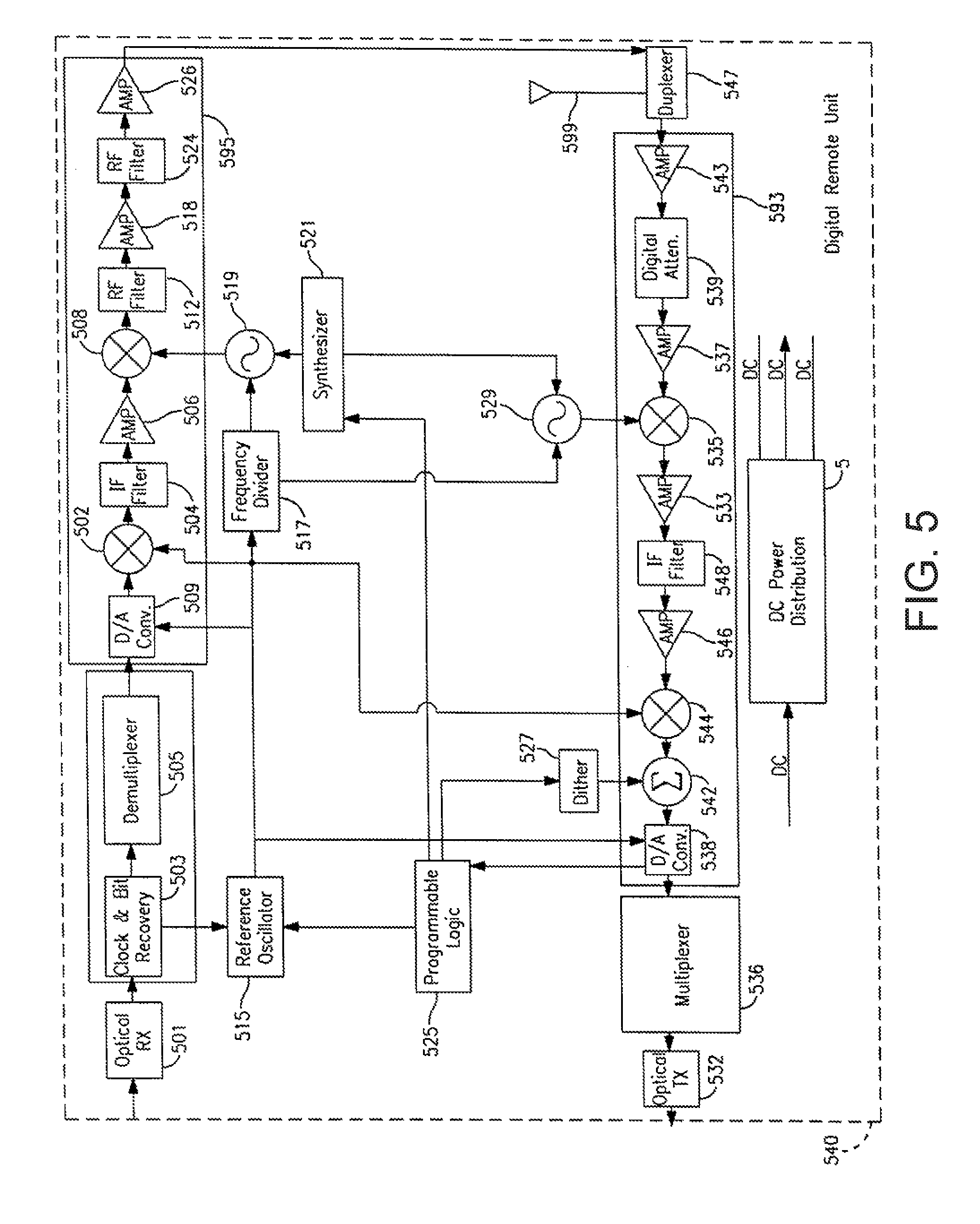
FIG. 5 is a block diagram of one embodiment of a digital remote unit according to the teachings of the present invention.
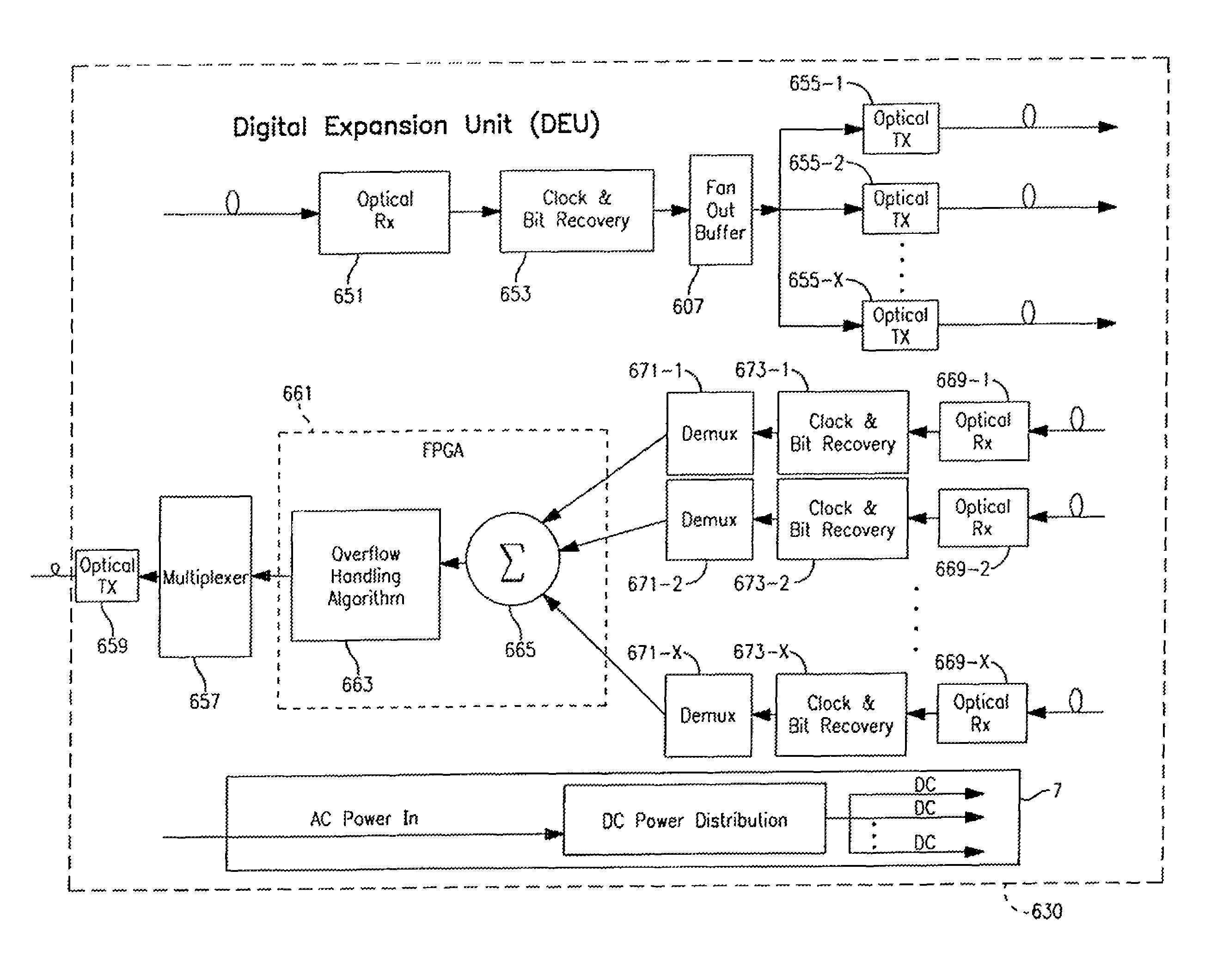
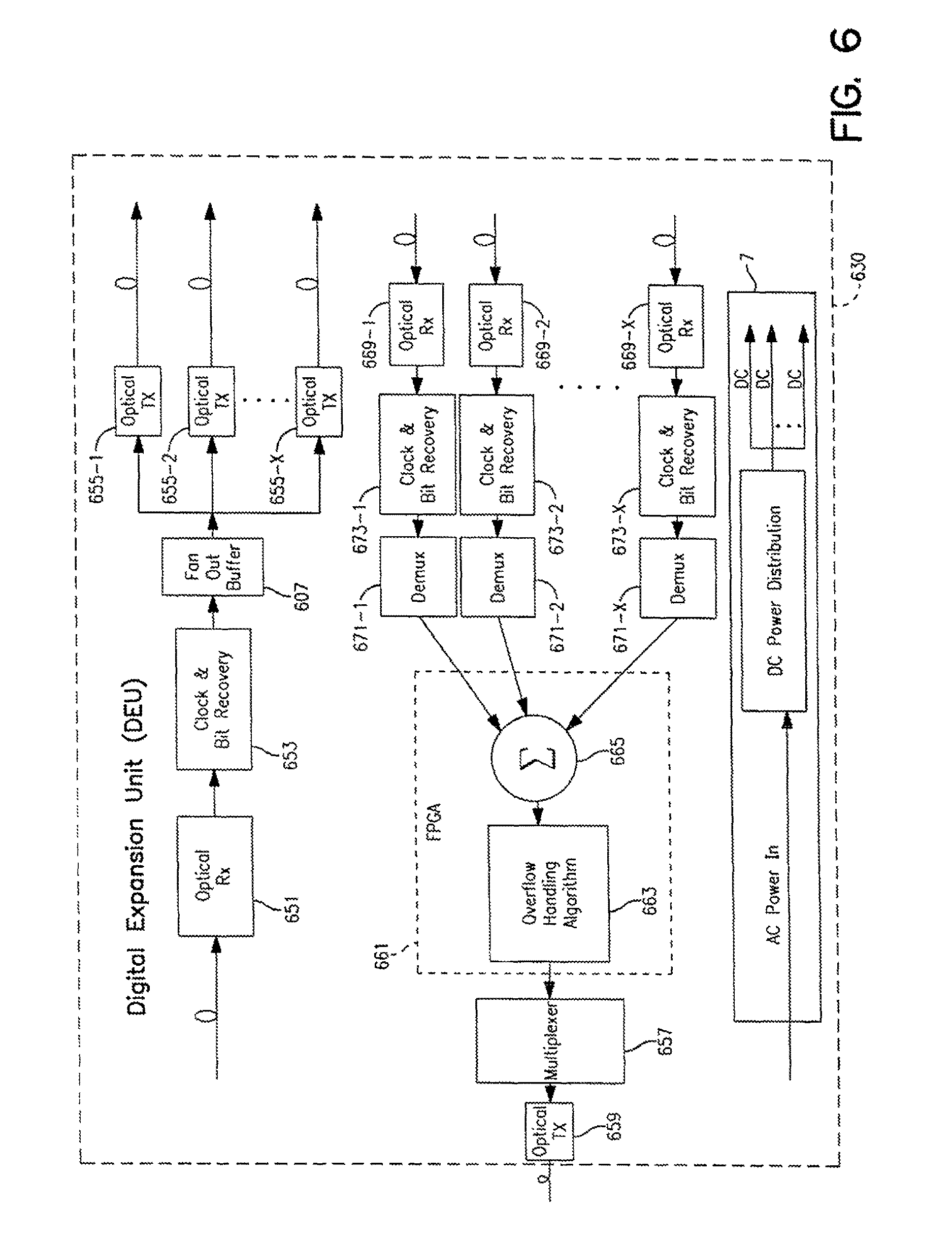
FIG. 6 is a block diagram of one embodiment of a digital expansion unit according to the teachings of the present invention.
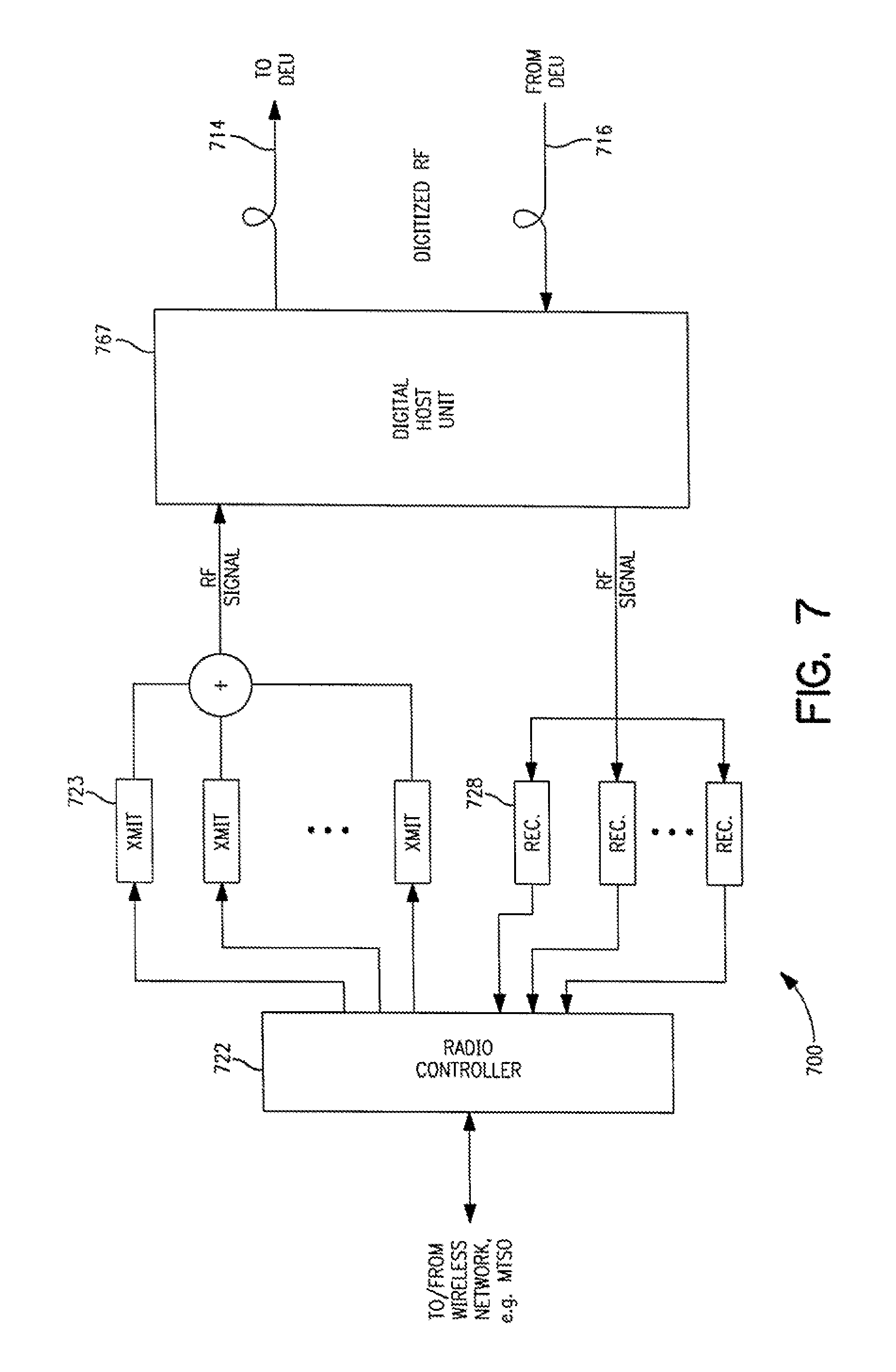
FIG. 7 is a block diagram of one embodiment of a microcell base station according to the teachings of the present invention.
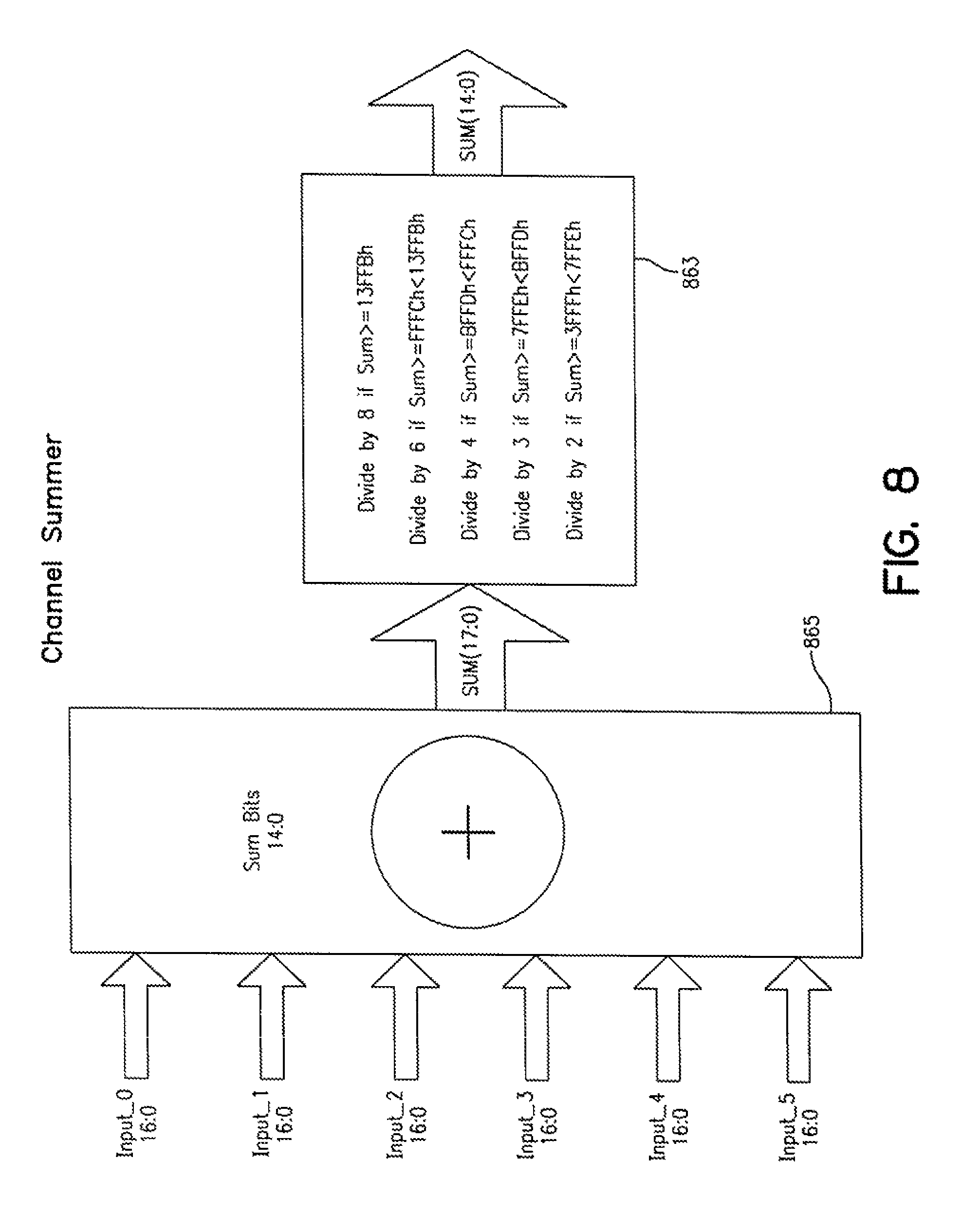
FIG. 8 is an illustration of one embodiment of an overflow algorithm for a channel summer according to the teachings of the present invention.
DETAILED DESCRIPTION
In the following detailed description of the preferred embodiments, reference is made to the accompanying drawings that form a part hereof, and in which is shown by way of illustration specific embodiments in which the invention may be practiced. It is to be understood that other embodiments may be utilized and structural changes may be made without departing from the scope of the present invention.
FIG. 1 is an illustration of one exemplary embodiment of a point-to-multipoint digital transport system shown generally at 100 and constructed according to the teachings of the present invention. The point-to-multipoint digital transport system 100 is shown distributed within a complex of tall shiny buildings (TSBs) 2. Although system 100 is shown in a complex of TSBs 2, it is understood that system 100 is not limited to this embodiment. Rather, system 100 in other embodiments is used to distribute signals in a single building, or other appropriate structure or indoor or outdoor location that exhibits high attenuation to RF signals. Advantageously, system 100 uses digital summing of digitized RF signals from multiple antennas to improve signal coverage in structures, such as TSBs.
Point-to-multipoint digital transport of RF signals is accomplished through a network of remote antenna units or digital remote units 40 and 40' and a digital host unit 20, which interfaces with a wireless network 5 which is coupled to the public switched telephone network (PSTN), or a mobile telecommunications switching office (MTSO) or other switching office/network. System 100 operates by transporting RF signals digitally over fiber optic cables. Signals received at DHU 20 are distributed to multiple DRUs 40 and 40' to provide coverage throughout a building complex. In addition, signals received at each of the DRUs 40 and 40' are summed together at the DHU 20 for interface to a wireless network.
In one embodiment, digital expansion unit DEU 30 is situated between the DHU 20 and one or more DRUs. In the forward path, DEU 30 expands the coverage area by splitting signals received from DHU 20 to a plurality of DRUs 40'. In the reverse path, DEU 30 receives signals from a plurality of DRUs 40', digitally sums the signals together and transports them to a DHU 20 or another DEU such as 30. This system allows for successive branching of signals using DEUs 30 and expanded coverage to multiple DRUs 40 and 40'. This system provides an efficient way of providing signal coverage for wireless communication without added attenuation loss and distance constraint found with analog systems. By using DEUs 30, antennas can be placed further from DHU 20 without adversely affecting signal strength since shorter fiber optic cables can be used.
Digital transport system 100 includes a wireless interface device (WID) 10 that provides an interface to a wireless network. In one embodiment, the WID 10 includes either conventional transmitters and receivers or all digital transmitter and receiver equipment, and interface circuitry to a mobile telecommunications switching office (MTSO). In one embodiment, the wireless interface device 10 is coupled to an MTSO via a T1 line and receives and transmits signals between the MTSO and the DHU 20. In another embodiment, the wireless interface device 10 is coupled to the public switched telephone network (PSTN). In one embodiment, WID 10 comprises a base station and connects directly to DHU 20 via coaxial cables. In another embodiment, WID 10 comprises a base station and wirelessly connects to DHU 20 via a bi-directional amplifier that is connected to an antenna. In one embodiment, the antenna is an outdoor antenna.
WID 10 communicates signals between wireless units and the wireless network via digital remote units DRUs 40 and 40'. WID 10 is coupled to DHU 20. The DHU 20 is coupled to at least one digital expansion unit DEU 30 and a plurality of DRUs 40. In addition, DEU 30 is coupled to a plurality of DRUs 40'. The DHU 20 receives RF signals from WID 10 and converts the RF signals to digital RF signals. DHU 20 further optically transmits the digital RF signals to multiple DRUs 40 either directly or via one or more DEUs 30.
Each DRU 40 and 40' is connected through a fiber optic cable (or optionally another high bandwidth carrier) to transport digital RF signals to one of DHU 20 or DEU 30. In one embodiment, the fiber optic cable comprises multimode fiber pairs coupled between the DRUs 40 and the DHU 20, between the DRUs 40 and 40' and the DEUs 30 and between the DEUs 30 and the DHU 20. In one embodiment, the DEU 30 is coupled to the DHU 20 via single mode fiber and the DEU 30 is coupled to the DRUs 40' via multimode fiber pairs. Although, transport system 100 has been described with fiber optic cable other carriers may be used, e.g., coaxial cable.
In another embodiment, the DHU 20 is coupled to the DRUs 40 by a direct current power cable in order to provide power to each DRU 40. In one embodiment, the direct current power cable delivers 48 VDC to each DRU 40 connected to the DHU 20. In another embodiment, the DEU 30 is coupled to DRUs 40' by a direct current power cable to provide power to each DRU 40'. In one embodiment, the direct current power cable delivers 48 VDC to each DRU 40' connected to the DEU 30. In an alternate embodiment, DRUs 40 and 40' are connected directly to a power supply. In one embodiment, the power supply provides DC power to the DRUs 40 and 40'. In an alternate embodiment, the power supply provides AC power to the DRUs 40 and 40'. In one embodiment, DRUs 40 and 40' each include an AC/DC power converter.
Both DHU 20 and DEU 30 split signals in the forward path and sum signals in the reverse path. In order to accurately sum the digital signals together at DHU 20 or DEU 30 the data needs to come in to the DHU 20 or DEU 30 at exactly the same rate. As a result all of the DRUs 40 and 40' need to be synchronized so that their digital sample rates are all locked together. Synchronizing the signals in time is accomplished by locking everything to the bit rate over the fiber. In one embodiment, the DHU 20 sends out a digital bit stream and the optical receiver at the DEU 30 or DRU 40 detects that bit stream and locks its clock to that bit stream. In one embodiment, this is being accomplished with a multiplexer chip set and local oscillators, as will be described below. Splitting and combining the signals in a digital state avoids the combining and splitting losses experienced with an analog system. In addition, transporting the digital signals over multimode fiber results in a low cost transport system that is not subject to much degradation.
The down-conversion and up-conversion of RF signals are implemented by mixing the signal with a local oscillator (LO) at both the DRUs and the DHU. In order for the original frequency of the RF signal to be restored, the signal must be up-converted with an LO that has exactly the same frequency as the LO that was used for down conversion. Any difference in LO frequencies will translate to an equivalent end-to-end frequency offset. In the embodiments described, the down conversion and up conversion LOs are at locations remote from one another. Therefore, in one preferred embodiment, frequency coherence between the local and remote LO's is established as follows: at the DHU end, there is a 142 MHz reference oscillator which establishes the bit rate of 1.42 GHz over the fiber. This reference oscillator also generates a 17.75 MHz reference clock which serves as a reference to which LO's at the DHU are locked.
At each of the DRUs, there is another 17.75 MHz clock, which is recovered from the optical bit stream with the help of the clock and bit recovery circuits. Because this clock is recovered from the bit stream generated at the host, it is frequency coherent with the reference oscillator at the host. A reference 17.75 MHz clock is then generated to serve as a reference for the remote local oscillators. Because the remote recovered bit clock is frequency coherent with the host master clock, the host and remote reference clocks, and any LO's locked to them, are also frequency coherent, thus ensuring that DHU and DRU LO's are locked in frequency. It is understood that in other embodiments the bit rate over the fiber may vary and the frequency of the clocks will also vary.
FIG. 2 is a block diagram of one embodiment of a communication system, shown generally at 200 and constructed according to the teachings of the present invention. In this embodiment, a digital host unit (DHU) 220 is coupled to a bi-directional amplifier (BDA) 211. The BDA 211 receives communication signals from a wireless interface device (WID) and transports the communication signals as RF signals to the DHU 220 and receives RF signals from DHU 220 and transmits the RF signals to the WID. The DHU 220 receives RF signals from the BDA 211 and digitizes the RF signals and optically transmits the digital RF signals to multiple DRUs via transmission lines 214-1 to 214-N. DHU 220 also receives digitized RF signals over transmission lines 216-1 to 216-N from a plurality of DRUs either directly or indirectly via DEUs, reconstructs the corresponding analog RF signals, and applies them to BDA 211. In one embodiment, DHU 220 receives signals directly from a plurality N of DRUs. The signals are digitally summed and then converted to analog signals and transmitted to BDA 211. In another embodiment, DHU 220 receives signals from one or more DEUs and one or more DRUs directly. Again, the signals are all digitally summed and then converted to analog signals and transmitted to BDA 211. The signals received via transmission lines 216-1 to 216-N may be received directly from a DRU or signals that are received by a DEU and summed together and then transported via 216-1 to 216-N to DHU 220 for additional summing and conversion for transport to BDA 211. DEUs provide a way to expand the coverage area and digitally sum signals received from DRUs or other DEUs for transmission in the reverse path to other DEUs or DHU 220. In one embodiment, transmission lines 214-1 to 214-N and 216-1 to 216-N comprise multimode fiber pairs. In an alternate embodiment, each fiber pair is replaced by a single fiber, carrying bi-directional optical signals through the use of wavelength division multiplexing (WDM). In an alternate embodiment, transmission lines 214-1 to 214-N and 216-1 to 216-N comprise single mode fibers. In one embodiment, N is equal to six. In an alternate embodiment, the number of transmission lines in the forward path direction 214-1 to 214-N is not equal to the number of transmission lines in the reverse path direction 216-1 to 216-N.
FIG. 3 is a block diagram of an alternate embodiment of a communication system shown generally at 300 and constructed according to the teachings of the present invention. Communication system 300 includes a base station 310 coupled to a DHU 320. Base station 310 includes conventional transmitters and receivers 323 and 328, respectively, and conventional radio controller or interface circuitry 322 to an MTSO or telephone switched network. DHU 320 is coupled to base station 310. DHU 320 is also coupled to transmission lines 314-1 to 314-M, which transmit in the forward path direction and transmission lines 316-1 to 316-M, which transmit in the reverse path direction.
DHU 320 essentially converts the RF spectrum to digital in the forward path and from digital to analog in the reverse path. In the forward path, DHU 320 receives the combined RF signal from transmitters 323, digitizes the combined signal and transmits it in digital format over fibers 314-1 to 314-M, which are connected directly to a plurality of DRUs or indirectly to one or more DRUs via one or more DEUs.
In one embodiment, DHU 320 receives signals directly from a plurality M of DRUs. The signals are digitally summed and then converted to analog signals and transmitted to base station 310. In another embodiment, DHU 320 receives signals from one or more DEUs and one or more DRUs directly. Again, the signals are all digitally summed and then converted to analog signals and transmitted to base station 310. The signals received via transmission lines 316-1 to 316-M may be received directly from a DRU or signals that are received by a DEU and summed together and then transported via 316-1 to 316-M to DHU 320 for additional summing and conversion for transport to base station 210. DEUs provide a way to expand the coverage area by splitting signals in the forward path and digitally summing signals received from DRUs or other DEUs in the reverse path for transmission upstream to other DEUs or a DHU. In the reverse path, DHU 320 also receives digitized RF signals over fibers 316-1 to 316-M from a plurality of DRUs, either directly or indirectly via DEUs, reconstructs the corresponding analog RF signal, and applies it to receivers 328.
In one embodiment, transmission lines 314-1 to 314-M and 316-1 to 316-M comprise multimode fiber pairs. In an alternate embodiment, each fiber pair is replaced by a single fiber, carrying bi-directional optical signals through the use of wavelength division multiplexing (WDM). In an alternate embodiment, transmission lines 314-1 to 314-M and 316-1 to 316-M comprise single mode fibers. In one embodiment, M is equal to six. In an alternate embodiment, the number of transmission lines in the forward path direction 314-1 to 314-M is not equal to the number of transmission lines in the reverse path direction 316-1 to 316-M.
Referring now to FIG. 4, there is shown one embodiment of a DHU 420 constructed according to the teachings of the present invention. DHU 420 includes an RF to digital converter 491 receiving the combined RF signals from a wireless interface device such as a base station, BDA or the like. RF to digital converter 491 provides a digitized traffic stream that is transmitted to multiplexer 466. Multiplexer 466 converts the parallel output of the A/D converter into a framed serial bit stream. At the output of the multiplexer is a 1 to P fan out buffer 407, which splits the digital signal P ways. There are P optical transmitters 431-1 to 431-P one feeding each of the P optical transmission lines 414-1 to 414-P. The digitized signals are applied to fibers 414-1 to 414-P for transmission to corresponding DRUs either directly or via DEUs. In one embodiment, P is equal to 6.
In one embodiment, DHU 420 includes an amplifier 450 that receives the combined RF signal from a wireless interface device such as a base station or BDA. The combined RF signal is amplified and then mixed by mixer 452 with a signal received from local oscillator 468. Local oscillator 468 is coupled to reference oscillator 415. In one embodiment the local oscillator is coupled to a frequency divider circuit 470, which is in turn coupled to reference oscillator 415. The local oscillator is locked to the reference oscillator 415 as a master clock so that the down conversion of the RF signals is the same as the up conversion. The result is end to end, from DHU to DRU, or DHU to one or more DEUs to DRU, no frequency shift in the signals received and transmitted. The local oscillator 463 is also coupled to a synthesizer circuit 476.
The output signal of mixer 452 is provided to amplifier 454 amplified and then filtered via intermediate frequency (IF) filter 456. The resultant signal is the combined RF signal converted down to an IF signal. The IF signal is mixed with another signal originating from the reference oscillator 415 via mixer 460. The output of mixer 460 is summed together at 462 with a signal produced by field programmable gate array (FPGA) 467. The output is then converted from an analog signal to a digital signal via analog/digital (A/D) converter 464 once converted the digital RF signal is applied to multiplexer 466. In one embodiment, the A/D converter 464 is a 14-bit converter handling a 14-bit signal. In other embodiments, the A/D converter 464 may be of any size to accommodate an appropriate signal. In one embodiment, the input signal from FPGA 467 is a dither signal from dither circuit 462 that adds limited out of band noise to improve the dynamic range of the RF signal.
In one embodiment, DHU 420 includes an alternating current to digital current power distribution circuit 6 that provides direct current power to each of the DRUs coupled to DHU 420.
DHU 420 further includes a plurality of digital optical receivers 418-1 to 418-P in the reverse path. Receivers 418-1 to 418-P each output an electronic digital signal, which is applied to clock and bit recovery circuits 445-1 to 445-P, respectively, for clock and bit recovery of the electronic signals. The signals are then applied to demultiplexers 441-1 to 441-P, respectively, which extract the digitized signals generated at the DRUs, as will be explained in detail below. Demultiplexers 441-1 to 441-P further extract alarm (monitoring) and voice information framed with the digitized signals. The digitized signals output at each demultiplexer 441-1 to 441-P are then applied to FPGA 467 where the signals are summed together and then applied to digital to RF converter 495. Converter 495 operates on the sum of the digitized signals extracted by demultiplexers 441-1 to 441-P, reconstructing baseband replicas of the RF signals received at all the digital remote units. The baseband replicas are then up-converted to their original radio frequency by mixing with a local oscillator 482 and filtering to remove image frequencies. Local oscillator 482 is coupled to synthesizer 476 and reference oscillator as discussed with respect to local oscillator 468 above.
In one embodiment, digital to RF converter 495 includes digital to analog (D/A) converter 484 coupled to an output of FPGA 467 the digitized RF signals are converted to analog RF signals and then mixed with a signal from reference oscillator 415 by mixer 492. The signal is then filtered by IF filter 490 and amplified by amplifier 488. The resultant signal is then mixed with a signal from local oscillator 482 and then applied to RF filter 484, amplifier 480 and RF filter 478 for transmission by a wireless interface device such as a BDA or base station.
In one embodiment, FPGA 467 includes an alarm/control circuit 474, which extracts overhead bits from DRUs to monitor error and alarm information. In one embodiment, the FPGA 467 includes a summer 498, which mathematically sums together the digital RF signals received from fibers 416-1 to 416-P. In another embodiment FPGA includes an overflow algorithm circuit 486 coupled to the output of summer 486. The algorithm circuit 496 allows the summed digital RF signals to saturate and keep the summed signal within a defined number of bits. In one embodiment, the algorithm circuit includes a limiter. In one embodiment, the RF signals are 14-bit signals and when summed and limited by summer 498 and overflow algorithm 496 result in a 14-bit output signal.
For example, in one embodiment each of the digital RF signals received from fibers 416-1 to 416-P, where P is equal to 6, comprise 14 bit inputs. All of those 6 different 14 bit inputs then go into summer 498. In order to allow for overflow, at least 17 bits of resolution is needed in the summer 498 to handle a worst-case scenario when all 6 of the 14 bit inputs are at full scale at the same time. In this embodiment, a 17-bit wide summer 498 is employed to handle that dynamic range. Coming out of summer 498 is needed a 14-bit signal going in the reverse path. In one embodiment, an algorithm circuit 496 for managing the overflow is implemented. In one embodiment, the summer and 498 and overflow algorithm 496 are included in FPGA 467. In one embodiment, overflow algorithm 496 acts like a limiter and allows the sum to saturate and keeps the summed signal within 14 bits. In an alternate embodiment, overflow algorithm circuit 496 controls the gain and scales the signal dynamically to handle overflow conditions.
FIG. 8 illustrates one embodiment of an algorithm 863 for a channel summer 865 in order to limit the sum of input signals 0 to 5 to 14 bits. In this embodiment, input signals 0 to 5 comprise 6 signals that are summed together by summer 865. The sum of input signals 0 to 5 is reduced to a signal having 14 bits or less by the algorithm 863. It is understood that the algorithm 865 is by example and is not meant to restrict the type of algorithm used to limit the sum of signals 0 to 5 to 14 bits or less.
For example, when the sum of the 6 input signals 0 to 5 is greater than or equal to 13FFBh then the sum is divided by 6 for a signal that is 14 bits or less. When the sum of the 6 input signals 0 to 5 is greater than 13FFBh but less than or equal to FFFCh then the sum is divided by 5 for a signal that is 14 bits or less. When the sum of the 6 input signals 0 to 5 is greater than FFFCh but less than BFFDh then the sum is divided by 4 for a signal that is 14 bits or less. When the sum of the 6 input signals 0 to 5 is greater BFFDh but less than 7FFEh then the sum is divided by 3 for a signal that is 14 bits or less. Finally, when the sum of the 6 input signals 0 to 5 is greater than 7FFEh but less than or equal to 3FFFh then the sum is divided by 2 for a signal that is 14 bits or less.
FIG. 5 is a block diagram of one embodiment of a digital remote unit (DRU) 540 constructed according to the teachings of the present invention. A digital optical receiver 501 receives the optical digital data stream transmitted from a DHU directly or via a DEU. Receiver 501 converts the optical data stream to a corresponding series of electrical pulses. The electrical pulses are applied to clock and bit recovery circuit 503. The series of electrical pulses are then applied to demultiplexer 505. Demultiplexer 505 extracts the digitized traffic signals and converts the signals from serial to parallel. The output parallel signal is then applied to digital to RF converter 595 for conversion to RF and transmission to duplexer 547. RF converter 595 is connected to the main antenna 599 through a duplexer 547. Accordingly, radio frequency signals originating from a wireless interface device are transmitted from main antenna 547.
In one embodiment, digital to RF converter 595 includes a digital-to-analog (D/A) converter 509, which reconstructs the analog RF signal and applies it to IF 504 and amplifier 506. The analog signal is mixed with an output signal of reference oscillator 515 by mixer 502. The output of amplifier 506 is mixed with a signal from local oscillator 519 that locks the RF signal with the return digital signal via reference oscillator 515 that is coupled to local oscillator 519. In one embodiment, the reference oscillator is coupled to frequency divider 517 that in turn is coupled to local oscillators 519 and 529. The local oscillators 519 and 529 are also coupled to synthesizer 521 that is coupled to programmable logic device 525.
RF signals received at main antenna 599 are passed through duplexer 547 to RF to digital converter 593. The RF signals are converted to digital signals and then applied to multiplexer 536 converted from parallel-to-serial and optically transmitted via optical transmitter 532 to a DEU or DHU.
In one embodiment, RF to digital converter 593 includes a first amplifier 543 that receives RF signals from duplexer 547, amplifies the signals and transmits them to digital attenuator 539. In one embodiment, amplifier 543 is a low noise amplifier. Digital attenuator 539 receives the amplified signals and digitally attenuates the signal to control the levels in case of an overload situation. RF to digital converter 593 further includes a second amplifier 537, which receives the attenuated signals, amplifies the signals and applies the amplified signals to mixer 535. Mixer 535 mixes the amplified signals with a signal received from local oscillator 529. The resultant signals are applied to a third amplifier 533 an IF filter 548 and a fourth amplifier 546 in series to down convert to an IF signal. The IF signal is then mixed with a signal from reference oscillator 515 and the mixed signal is summed with a signal from dither circuit 527. The resultant signal is applied to analog-to-digital converter 538 and converted to a digital signal. The output digital signal is then applied to a multiplexer 536. In one embodiment, the multiplexer 536 multiplexes the signal together with a couple of extra bits to do framing and control information. In one embodiment, multiplexer 536, clock and bit recovery circuit and demultiplexer 505 comprise a multiplexer chip set.
Programmable logic circuit 525 programs synthesizer 521 for the reference oscillator and for the up and down conversion of local oscillators 519 and 529. The programmable logic circuit 525 looks for error conditions, for out of lock conditions on the oscillators and reports error modes and looks for overflow condition in the A/D converter 538. If an overflow condition occurs the programmable logic circuit 525 indicates that you are saturating and adds some extra attenuation at digital attenuator 539 in order to reduce the RF signal levels coming in from RF antenna 599 and protect the system from overload.
In one embodiment, DRU 540 includes an internal direct current power distribution system 5. In one embodiment, the distribution system receives 48 VDC and internally distributes 3 outputs of +3.8V, +5.5V and +8V.
FIG. 6 is a block diagram of one embodiment of a digital expansion unit (DEU) 630 constructed according to the teachings of the present invention. DEU 630 is designed to receive optical signals and transmit optical signals. An optical receiver 651 receives digitized RF signals and transmits them to clock and bit recovery circuit 653 that performs clock and bit recovery to lock the local clock and clean up the signal. The signals are then split into X RF digital signals by 1 to X fan out buffer 607. The signals are then transmitted via optical transmitters 655-1 to 655-X to X receiving units such as DEUs or DRUs. The X receiving units may be any combination of DEUs or DRUs. In one embodiment, X is equal to six.
DEU 630 also includes optical receivers 669-1 to 669-X, which receive digitized RF signals directly from DRUs or indirectly via DEUs. In operation the signals are received, applied to clock and bit recovery circuits 673-1 to 673-X respectively to lock the local clock and clean up the signals and then applied to demultiplexers 671-1 to 671-X. Demultiplexers 671-1 to 671-X each extract the digitized traffic and apply the samples to field programmable gate array 661. The signals are summed together digitally and transmitted to multiplexer 657, which mulitplexes the signal together with a couple of extra bits to do framing and control information. In addition, the multiplexer 657 converts the signals parallel to serial. The signals are then applied to optical transmitter 659 for further transmission. In one embodiment, the signals are directly transmitted to a DHU or indirectly via one or more additional DEUs.
In one embodiment, the FPGA 661 includes summer 665, which mathematically sums together the digital RF signals received from demultiplexers 671-1 to 671-X. In another embodiment, FPGA 661 includes an overflow algorithm circuit 663 coupled to the output of summer 665. The algorithm circuit 663 allows the summed digital RF signals to saturate and keep the summed signal within a defined number of bits. In one embodiment, the algorithm circuit includes a limiter. In one embodiment, the RF signals are 14-bit signals and when summed and limited by summer 665 and overflow algorithm 663 result in a 14-bit output signal.
In one embodiment, DEU 630 includes an alternating current to digital current power distribution circuit 7 that provides direct current power to each of the DRUs coupled to DEU 630.
In an alternate embodiment, the digital host unit (DHU) and wireless interface device (WID) are located some distance from the building being served. The DHU in the building is replaced by a DEU, and the link between that DEU and the remotely located DHU is via single mode fiber. FIG. 7 is a block diagram of this embodiment. A microcell base station shown generally at 700 includes conventional transmitters and receivers 723 and 728, respectively, and conventional radio controller or interface circuitry 722. In the forward path, a DHU 767 receives the combined RF signal from transmitters 723, digitizes the combined signal and transmits it in digital format over single mode fiber to a DEU. In the reverse path, DHU 767 receives digitized RF signal from a DEU, reconstructs the corresponding analog RF signal, and applies it to receivers 728.
In another alternate embodiment, the wireless interface device (WID) is a software defined base station, and the interface between the DHU and WID takes place digitally, eliminating the need for the RF to digital conversion circuitry in the DHU.
CONCLUSION
A digital radio frequency transport system has been described. The transport system includes a digital host unit and at least two digital remote units coupled to the digital host unit. The digital host unit includes shared circuitry that performs bi-directional simultaneous digital radio frequency distribution between the digital host unit and the at least two digital remote units.
In addition, a digital radio frequency transport system has been described. The transport system includes a digital host unit and at least one digital expansion unit coupled to the digital host unit. The transport system further includes at least two digital remote units, each coupled to one of the digital host unit and the digital expansion unit. The digital host unit includes shared circuitry that performs bi-directional simultaneous digital radio frequency distribution between the digital host unit and that at least two digital remote units.
Further, a method of performing point-to-multipoint radio frequency transport has been described. The method includes receiving analog radio frequency signals at a digital host unit and converting the analog radio frequency signals to digitized radio frequency signals. The method also includes splitting the digitized radio frequency signals into a plurality of a digital radio frequency signals and optically transmitting the digital radio frequency signals to a plurality of digital remote units. The method further includes receiving the digital radio frequency signals at a plurality of digital remote units, converting the digital radio frequency signals to analog radio frequency signals and transmitting the signals via a main radio frequency antenna at each of the plurality of digital remote units.
Although specific embodiments have been illustrated and described herein, it will be appreciated by those of ordinary skill in the art that any arrangement which is calculated to achieve the same purpose may be substituted for the specific embodiments shown. For example, a digital remote unit is not limited to the receipt and summing and splitting and transmitting of digitized radio frequency signals. In other embodiments, the digital host unit is capable of receiving and summing analog radio frequency signals in addition to or instead of digitized radio frequency signals. As well, the digital host unit is capable of splitting and transmitting analog radio frequency signals in addition to or instead of digitized radio frequency signals. This application is intended to cover any adaptations or variations of the present invention. Therefore, it is intended that this invention be limited only by the claims and the equivalents thereof.
* * * * *
References
D00000
D00001
D00002
D00003
D00004
D00005
D00006
D00007
D00008
XML
uspto.report is an independent third-party trademark research tool that is not affiliated, endorsed, or sponsored by the United States Patent and Trademark Office (USPTO) or any other governmental organization. The information provided by uspto.report is based on publicly available data at the time of writing and is intended for informational purposes only.
While we strive to provide accurate and up-to-date information, we do not guarantee the accuracy, completeness, reliability, or suitability of the information displayed on this site. The use of this site is at your own risk. Any reliance you place on such information is therefore strictly at your own risk.
All official trademark data, including owner information, should be verified by visiting the official USPTO website at www.uspto.gov. This site is not intended to replace professional legal advice and should not be used as a substitute for consulting with a legal professional who is knowledgeable about trademark law.