Slide covers for head to head sliders and methods of assembly and use thereof
Omote , et al. De
U.S. patent number 10,492,572 [Application Number 16/119,069] was granted by the patent office on 2019-12-03 for slide covers for head to head sliders and methods of assembly and use thereof. This patent grant is currently assigned to YKK Corporation of America. The grantee listed for this patent is YKK Corporation of America. Invention is credited to Suguru Ogura, Sayuri Omote, Mingsi Wang.


View All Diagrams
| United States Patent | 10,492,572 |
| Omote , et al. | December 3, 2019 |
| **Please see images for: ( Certificate of Correction ) ** |
Slide covers for head to head sliders and methods of assembly and use thereof
Abstract
Various implementations include a slide fastener with head to head sliders that prevents the sliders from moving apart from each other unintentionally and prevents liquid from flowing through the slide fastener. The slide fastener includes first and second sliders that are slidably coupled to a pair of interlocking stringers. The slide fastener also includes slider covers that are each coupled to a respective slider. The slider covers engage each other when the sliders are pulled together. In some implementations, the engagement of the slider covers prevents unintentional separation and/or prevents liquid from flowing out of or into a cavity defined by an inner side of the slider covers that extends around facing front faces of the sliders on one side of the interlocking stringers.
| Inventors: | Omote; Sayuri (Toyoma, JP), Ogura; Suguru (Taipei, TW), Wang; Mingsi (Macon, GA) | ||||||||||
|---|---|---|---|---|---|---|---|---|---|---|---|
| Applicant: |
|
||||||||||
| Assignee: | YKK Corporation of America
(Marietta, GA) |
||||||||||
| Family ID: | 68695883 | ||||||||||
| Appl. No.: | 16/119,069 | ||||||||||
| Filed: | August 31, 2018 |
| Current U.S. Class: | 1/1 |
| Current CPC Class: | A44B 19/32 (20130101); A44B 19/265 (20130101); A44B 19/26 (20130101) |
| Current International Class: | A44B 19/26 (20060101); A44B 19/32 (20060101) |
References Cited [Referenced By]
U.S. Patent Documents
| 4395891 | August 1983 | Remington |
| 4976120 | December 1990 | Terada |
| 6062051 | May 2000 | Nam |
| 6510593 | January 2003 | Kim |
| 7073233 | July 2006 | Leva |
| D526931 | August 2006 | Koenig et al. |
| 7506417 | March 2009 | Yoneoka |
| 7533451 | May 2009 | Akashi |
| 9902529 | February 2018 | Reinders |
| 2005/0109072 | May 2005 | Ling |
| 201976897 | Sep 2011 | CN | |||
| 204169190 | Feb 2015 | CN | |||
| 1300094 | Apr 2003 | EP | |||
| 2011004500 | Jan 2011 | WO | |||
Other References
|
Slider with plastic water blocker, https//www.ykkfastening.com/products/search/detail, Accessed Nov. 27, 2018. cited by applicant. |
Primary Examiner: Batson; Victor D
Assistant Examiner: Do; Rowland
Attorney, Agent or Firm: Meunier Carlin & Curfman LLC
Claims
The invention claimed is:
1. A slide fastener comprising: a first slider and a second slider that are slidably coupled to a pair of interlocking stringers, each slider having an interior wing, an exterior wing, a connecting portion extending between at least a portion of facing and spaced apart surfaces of the interior wing and the exterior wing, and a crown that extends from an outer surface of the exterior wing, wherein each of the interior wing and the exterior wing comprises a front face; a plug slider cover comprising a main body having an inner side and an outer side, an engagement face extending between the inner side and the outer side, one or more plugs that extend from the engagement face of the plug slider cover, and one or more protrusions that extend from the inner side of the main body toward a plane that includes surfaces of the interlocking stringers that face the protrusions, wherein the inner side of the plug slider cover abuts the outer surface of the exterior wing of the first slider; and a socket slider cover comprising a main body having an inner side and an outer side, an engagement face extending between the inner side and the outer side of the main body of the socket slider cover, the engagement face of the main body of the socket slider cover defining at least one socket, and one or more protrusions that extend from the inner side of the main body of the socket slider cover toward the plane that includes surfaces of the interlocking stringers that face the protrusions, wherein the inner side of the socket slider cover abuts the outer surface of the exterior wing of the second slider, wherein the one or more plugs of the plug slider cover engage the at least one socket of the socket slider cover when the first and second sliders are urged toward each other, and the one or more plugs of the plug slider cover disengage the at least one socket of the socket slider cover when the first and second sliders are urged away from each other.
2. The slide fastener of claim 1, wherein the inner and outer sides of the plug slider cover define an opening that extends through the main body of the plug slider cover, and the crown of the first slider extends through the opening and compresses a portion of the plug slider cover disposed between the crown and the outer surface of the exterior wing of the first slider, and the inner and outer sides of the main body of the socket slider cover defining an opening that extends through the main body of the socket slider cover, and the crown of the second slider extends through the opening that extends through the main body of the socket slider cover and compresses a portion of the socket slider cover disposed between the crown and the outer surface of the exterior wing of the second slider.
3. The slide fastener of claim 1, wherein the distal ends of the one or more protrusions of the plug slider cover and the socket slider cover contact the adjacent surfaces of the interlocking stringers.
4. The slide fastener of claim 1, wherein engagement faces of the plug slider cover and the socket slider cover are sealed together when the one or more plugs are engaged with the at least one socket.
5. The slide fastener of claim 4, wherein: the engagement face of the plug slider cover comprises a lip that extends from and along at least a portion of the engagement face, the lip being spaced apart from the outer side and the inner side of the main body of the plug slider cover; and the engagement face of the socket slider cover defines a channel that is in communication with the at least one socket, the channel receiving the lip of the engagement face of the plug slider cover when the one or more plugs are engaged with the at least one socket.
6. The slide fastener of claim 4, wherein inner sides of the covers and the portions of the stringers that are between the front faces of the sliders define a cavity when the engagement faces of the plug slider covers and the socket slider cover abut each other, the inner sides of the covers preventing liquid from flowing between the cavity and outer sides of the covers.
7. The slide fastener of claim 1, wherein the one or more plugs comprises a first lateral arm and a second lateral arm, each arm comprising a neck portion and a head portion, wherein the neck portion extends between the head portion and the engagement face, the head portion is spaced apart from the engagement face, the arms are biased in lateral directions, and the neck portion has a width that is less than a width of the head portion.
8. The slide fastener of claim 1, wherein the one or more protrusions of the plug slider cover comprise a first lateral protrusion and a second lateral protrusion, the first and second lateral protrusions each comprise a contact face, and the contact faces of the first and second lateral protrusions abut at least a portion of the front face of the exterior wing of the first slider.
9. The slide fastener of claim 8 wherein the contact face is arcuate shaped.
10. The slide fastener of claim 8, wherein the contact face is planar.
11. The slide fastener of claim 8, wherein a contour of the contact face corresponds to a contour of the respective portion of the front face that the contact face abuts.
12. The slide fastener of claim 8, wherein each slider comprises a first lateral exterior retaining flange that extends from the facing surface of the exterior wing adjacent a first lateral side of the exterior wing, a second lateral exterior retaining flange that extends from the facing surface of the exterior wing adjacent a second lateral side of the exterior wing, a first lateral interior retaining flange that extends from the facing surface of the interior wing adjacent a first lateral side of the interior wing, and a second lateral interior retaining flange that extends from the facing surface of the interior wing adjacent a second lateral side of the interior wing, wherein each retaining flange has distal end, the distal ends of the first lateral exterior retaining flange and the first lateral interior retaining flange are aligned between the facing surfaces and are spaced apart from each other, the distal ends of the second lateral exterior retaining flange and the second lateral interior retaining flange are aligned between the facing surfaces and are spaced apart from each other, and the distal ends of the first and second lateral exterior retaining flanges and distal ends of the first and second lateral protrusions are coplanar.
13. The slide fastener of claim 8, wherein the contact faces of the first and second lateral protrusions are biased medially toward the portions of the front faces of the exterior wing of the first slider that the first and second lateral protrusions abut.
14. The slide fastener of claim 13, wherein at least a portion of each contact face lies within a plane that extends at an angle that is greater than 0.degree. and less than 90.degree. relative to a plane that is orthogonal to the inner side of the main body and extends through the respective protrusion.
15. The slide fastener of claim 1, wherein the main body of the plug slider cover and/or the socket slider cover comprises a rear portion that is opposite and spaced apart from the engagement face of the respective cover, and the rear portion is compressed between the outer surface of the exterior wing of the respective slider and the crown of the respective.
16. The slide fastener of claim 15, wherein the rear portion of the main body of the respective cover is compressed between the outer surface of the exterior wing of the respective slider and the crown of the respective slider after a distal end of the crown of the respective slider is pushed toward the outer surface of the exterior wing of the respective slider.
17. The slide fastener of claim 16, wherein the opening defined by the inner and outer sides of the main body of the respective cover is further defined by the rear portion of the respective cover.
18. The slide fastener of claim 1, wherein the plug slider cover and the socket slider cover comprise a polymer material.
19. The slide fastener of claim 1, wherein the engagement face of the plug slider cover is arcuate shaped.
20. The slide fastener of claim 1, wherein the engagement face of the plug slider cover has one or more planar shaped portions.
21. A slide fastener comprising: a first slider and a second slider for slidably coupling on a pair of interlocking stringers, each slider having an interior wing, an exterior wing, a connecting portion extending between at least a portion of facing and spaced apart surfaces of the interior wing and the exterior wing, and a crown that extends from an outer surface of the exterior wing, wherein each of the interior wing and the exterior wing comprises a front face; a plug slider cover comprising a main body having an inner side and an outer side defining an opening that extends through the main body of the plug slider cover, an engagement face extending between the inner side and the outer side, one or more plugs that extend from the engagement face of the plug slider cover, and the crown of the first slider extends through the opening and compresses a portion of the plug slider cover disposed between the crown and the outer surface of the exterior wing of the first slider; and a socket slider cover comprising a main body having an inner and an outer side defining an opening, an engagement face extending between the inner side and the outer side of the main body of the socket slider cover, the engagement face of the main body of the socket slider cover defining at least one socket, and the crown of the second slider extends through the opening that extends through the main body of the socket slider cover and compresses a portion of the socket slider cover disposed between the crown and the outer surface of the exterior wing of the second slider, wherein: the one or more plugs of the plug slider cover engage the at least one socket of the socket slider cover when the first and second slider are urged toward each other, and the one or more plugs of the plug slider cover disengage the at least one socket of the socket slider cover when the first and second slider are urged away from each other.
Description
BACKGROUND
Typical head to head sliders are not able to prevent liquid from passing between the sliders when they are urged together. For example, head to head sliders may be used on coolers to attach a lid to a body of the cooler, on backpacks and tents to access openings, and on clothing (e.g., outerwear). In addition, head to head sliders may move away from each other due to vibration of the object to which the sliders are attached, gravity, or other forces acting on the sliders.
Thus, there is a need in the art to provide a slide fastener with head to head sliders that prevents the flow of a liquid (e.g., water) through the slide fastener. There is also a need in the art to provide a slide fastener with head to head sliders that prevents the head to head sliders from moving apart unintentionally.
BRIEF SUMMARY
Various implementations include a slide fastener that comprises a first slider and a second slider, a plug slider cover, and a socket slider cover. The first slider and the second slider are slidably coupled to a pair of interlocking stringers. Each slider has an interior wing, an exterior wing, a connecting portion extending between at least a portion of facing and spaced apart surfaces of the interior wing and the exterior wing, and a crown that extends from an outer surface of the exterior wing. Each of the interior wing and the exterior wing comprise a front face. The plug slider cover comprises a main body that has an inner side and an outer side and an engagement face that extends between the inner side and the outer side. The plug slider cover also includes one or more plugs that extend from the engagement face of the plug slider cover and one or more protrusions that extend from the inner side of the main body toward a plane that includes surfaces of the interlocking stringers that face the protrusions. The inner side of the plug slider cover abuts the outer surface of the exterior wing of the first slider. The socket slider cover comprises a main body that has an inner side and an outer side and an engagement face that extends between the inner side and the outer side of the main body of the socket slider cover. The socket slider cover also includes one or more protrusions that extend from the inner side of the main body of the socket slider cover toward the plane that includes surfaces of the interlocking stringers that face the protrusions. The engagement face of the main body of the socket slider cover defines at least one socket. And, the inner side of the socket slider cover abuts the outer surface of the exterior wing of the second slider. The one or more plugs of the plug slider cover engage the at least one socket of the socket slider cover when the first and second slider are urged toward each other, and the one or more plugs of the plug slider cover disengage the at least one socket of the socket slider cover when the first and second slider are urged away from each other.
In some implementations, the inner and outer sides of the plug slider cover define an opening that extends through the main body of the plug slider cover, and the crown of the first slider extends through the opening and compresses a portion of the plug slider cover disposed between the crown and the outer surface of the exterior wing of the first slider. The inner and outer sides of the main body of the socket slider cover define an opening that extends through the main body of the socket slider cover, and the crown of the second slider extends through the opening that extends through the main body of the socket slider cover and compresses a portion of the socket slider cover disposed between the crown and the outer surface of the exterior wing of the second slider.
In some implementations, the distal ends of the one or more protrusions of the plug slider cover and the socket slider cover contact the adjacent surfaces of the interlocking stringers.
In some implementations, engagement faces of the plug slider cover and the socket slider cover are sealed together when the one or more plugs are engaged with the at least one socket. For example, in some implementations, the engagement face of the plug slider cover comprises a lip that extends from and along at least a portion of the engagement face. The lip is spaced apart from the outer side and the inner side of the main body of the plug slider cover. The engagement face of the socket slider cover defines a channel that is in communication with the at least one socket. The channel receives the lip of the engagement face of the plug slider cover when the one or more plugs are engaged with the at least one socket. And, in some implementations, inner sides of the covers and the portions of the stringers that are between the front faces of the sliders define a cavity when the engagement faces of the plug slider covers and the socket slider cover abut each other. The inner sides of the covers prevent liquid from flowing between the cavity and outer sides of the covers.
In some implementations, the one or more plugs comprises a first lateral arm and a second lateral arm. Each arm comprises a neck portion and a head portion. The neck portion extends between the head portion and the engagement face, the head portion is spaced apart from the engagement face, the arms are biased in lateral directions, and the neck portion has a width that is less than a width of the head portion.
In some implementations, the one or more protrusions of the plug slider cover comprise a first lateral protrusion and a second lateral protrusion. The first and second lateral protrusions each comprise a contact face, and the contact faces of the first and second lateral protrusions abut at least a portion of the front face of the exterior wing of the first slider. For example, in some implementations, the contact face is arcuate shaped. In other implementations, the contact face is planar. In some implementations, a contour of the contact face corresponds to a contour of the respective portion of the front face that the contact face abuts. And, in some implementations, each slider comprises a first lateral exterior retaining flange that extends from the facing surface of the exterior wing adjacent a first lateral side of the exterior wing, a second lateral exterior retaining flange that extends from the facing surface of the exterior wing adjacent a second lateral side of the exterior wing, a first lateral interior retaining flange that extends from the facing surface of the interior wing adjacent a first lateral side of the interior wing, and a second lateral interior retaining flange that extends from the facing surface of the interior wing adjacent a second lateral side of the interior wing. Each retaining flange has a distal end, and the distal ends of the first lateral exterior retaining flange and the first lateral interior retaining flange are aligned between the facing surfaces and are spaced apart from each other. The distal ends of the second lateral exterior retaining flange and the second lateral interior retaining flange are aligned between the facing surfaces and are spaced apart from each other, and the distal ends of the first and second lateral exterior retaining flanges and distal ends of the first and second lateral protrusions are coplanar. In some implementations, the contact faces of the first and second lateral protrusions are biased medially toward the portions of the front faces of the exterior wing of the first slider that the first and second lateral protrusions abut. For example, in some implementations, at least a portion of each contact face lies within a plane that extends at an angle that is greater than 0.degree. and less than 90.degree. relative to a plane that is orthogonal to the inner side of the main body and extends through the respective protrusion.
In some implementations, the main body of the plug slider cover and/or the socket slider cover comprises a rear portion that is opposite and spaced apart from the engagement face of the respective cover, and the rear portion is compressed between the outer surface of the exterior wing of the respective slider and the crown of the respective. For example, in some implementations, the rear portion of the main body of the respective cover is compressed between the outer surface of the exterior wing of the respective slider and the crown of the respective slider after a distal end of the crown of the respective slider is pushed toward the outer surface of the exterior wing of the respective slider. In a further implementation, the opening defined by the inner and outer sides of the main body of the respective cover is further defined by the rear portion of the respective cover.
In some implementations, the plug slider cover and the socket slider cover comprise a polymer material.
In some implementations, the engagement face of the plug slider cover is arcuate shaped. And, in some implementations, the engagement face of the plug slider cover has one or more planar shaped portions.
In various other implementations, a slide fastener comprises a first slider and a second slider for slidably coupling on a pair of interlocking stringers, a plug slider cover, and a socket slider cover. Each slider has an interior wing, an exterior wing, a connecting portion extending between at least a portion of facing and spaced apart surfaces of the interior wing and the exterior wing, and a crown that extends from an outer surface of the exterior wing. Each of the interior wing and the exterior wing comprise a front face. The plug slider cover comprises a main body that has an inner side and an outer side, an engagement face that extends between the inner side and the outer side, and one or more plugs that extend from the engagement face of the plug slider cover. The crown of the first slider extends through the opening and compresses a portion of the plug slider cover disposed between the crown and the outer surface of the exterior wing of the first slider. The socket slider cover comprises a main body that has an inner side and an outer side and an engagement face that extends between the inner side and the outer side of the main body of the socket slider cover. The engagement face of the main body of the socket slider cover defines at least one socket, and the crown of the second slider extends through the opening that extends through the main body of the socket slider cover and compresses a portion of the socket slider cover disposed between the crown and the outer surface of the exterior wing of the second slider. The one or more plugs of the plug slider cover engage the at least one socket of the socket slider cover when the first and second slider are urged toward each other, and the one or more plugs of the plug slider cover disengage the at least one socket of the socket slider cover when the first and second slider are urged away from each other.
BRIEF DESCRIPTION OF THE DRAWINGS
Example features and implementation are disclosed in the accompanying drawings. However, the present disclosure is not limited to the arrangements and instrumentalities shown. Furthermore, various features may not be drawn to scale.
FIG. 1 illustrates an exterior perspective view of a portion of a slide fastener according to one implementation.
FIG. 2 illustrates a front end view of the first slider shown in FIG. 1.
FIG. 3 illustrates a right side view of the first slider shown in FIG. 2.
FIG. 4. illustrates a front end view of the second slider shown in FIG. 1.
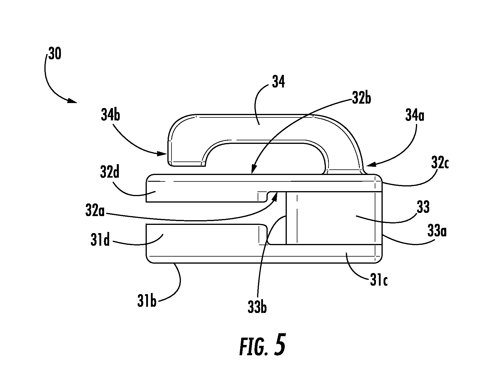
FIG. 5 illustrates a right side view of the second slider shown in FIG. 4.
FIG. 6 illustrates a right side view of the slide fastener shown in FIG. 1. A portion of the interlocking stringer 40a that is not disposed within the sliders 20, 30 and the coupling elements have been removed from the view.
FIG. 7 illustrates a rear end view of the slide fastener shown in FIG. 1 as viewed through the X-X plane shown in FIG. 1.
FIG. 8A illustrates an exterior perspective view of the plug slider cover shown in FIG. 1.
FIG. 8B illustrates an interior plan view of the plug slider cover shown in FIG. 8A.
FIG. 8C illustrates an interior perspective view of the engagement of the contact face of the protrusions of the plug slider cover of FIG. 8A with the front face of the exterior wing of the first slider shown in FIG. 1.
FIG. 8D illustrates a front end view of the plug slider cover shown in FIG. 8A.
FIG. 8E illustrates a right side view of the plug slider cover shown in FIG. 8A.
FIG. 8F illustrates a plug slider cover according to another implementation that has protrusions that are not biased toward the slider.
FIG. 8G illustrates an exterior perspective view of a plug slider cover according to another implementation.
FIG. 9A illustrates an exterior perspective view of the socket slider cover shown in FIG. 1.
FIG. 9B illustrates an interior plan view of the socket slider cover shown in FIG. 9A.
FIG. 9C illustrates an interior perspective view of the socket slider cover shown in FIG. 9A.
FIG. 9D illustrates a front end view of the socket slider cover shown in FIG. 9A.
FIG. 9E illustrates a right side view of the socket slider cover shown in FIG. 10.
FIG. 9F illustrates an exterior plan view of the socket slider cover shown in FIG. 9A.
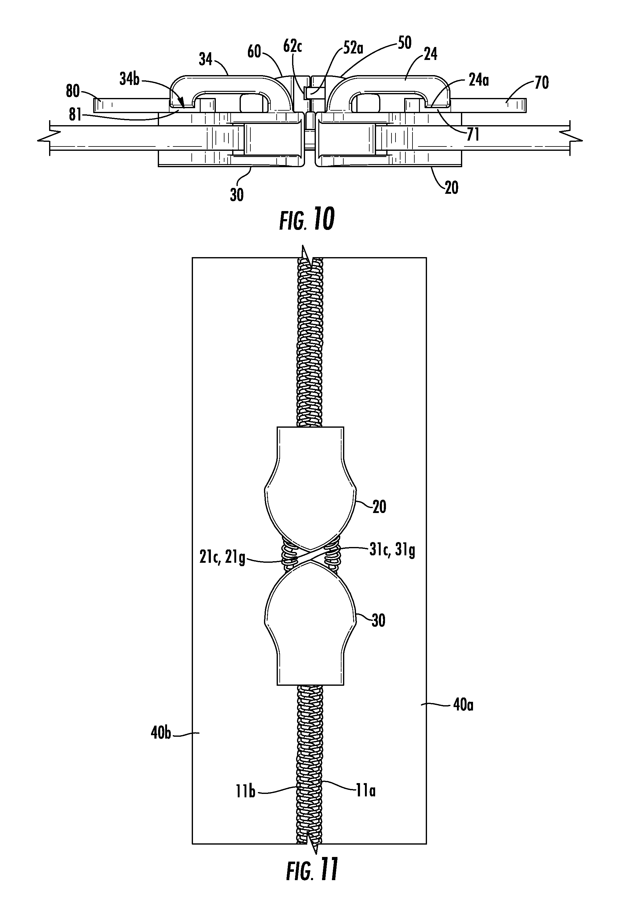
FIG. 10 illustrates a cross sectional view of the slide fastener as taken through the Y-Y plane shown in FIG. 1. The coupling elements have been removed from this view.
FIG. 11 illustrates an interior plan view of the slide fastener shown in FIG. 1.
FIG. 12A illustrates a slide fastener having discontinuous teeth according to one implementation, and FIG. 12B illustrates a cross sectional view of the slide fastener in FIG. 12A through the D-D line.
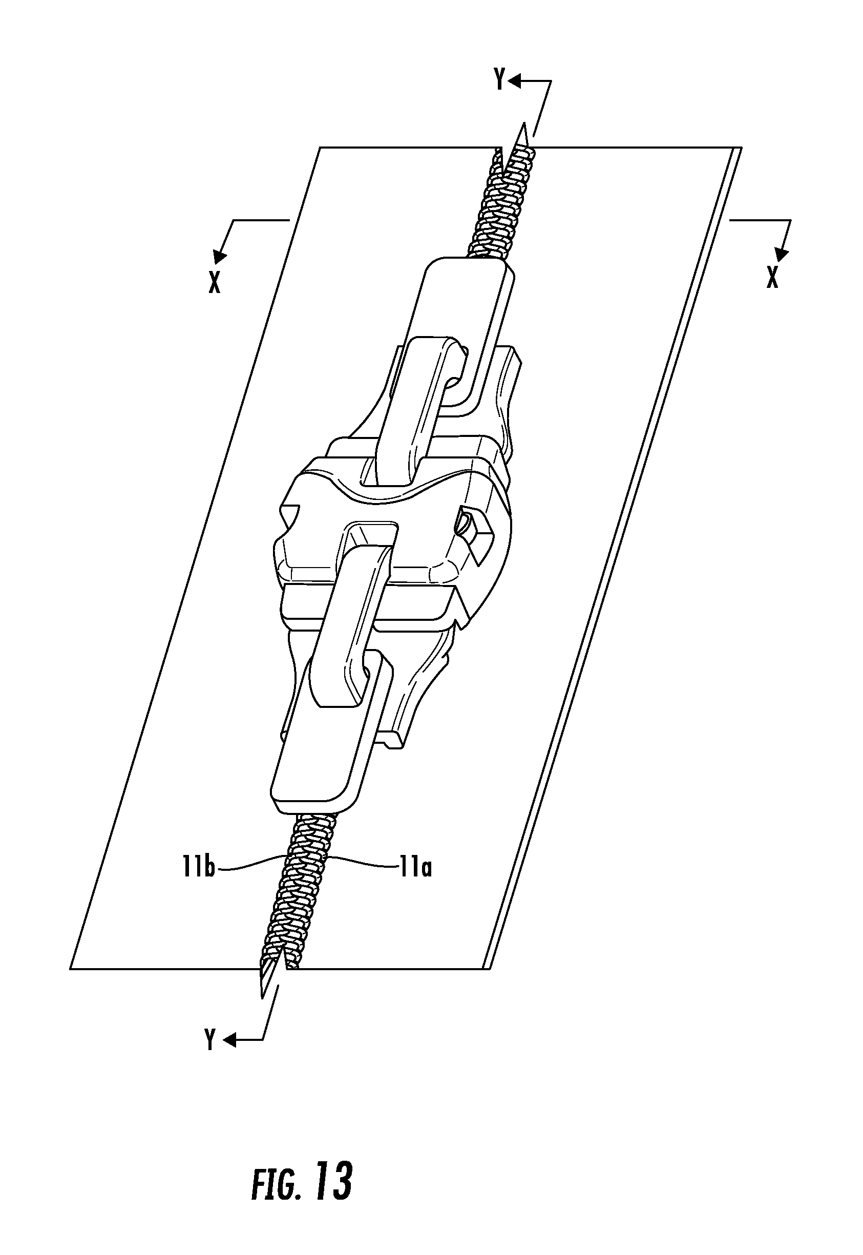
FIG. 13 illustrates a slide fastener having continuous coupling elements coupled to the exterior surfaces of the tapes, according to another implementation.
DETAILED DESCRIPTION
Various implementations include a slide fastener with head to head sliders that prevents the sliders from moving apart from each other unintentionally and prevents liquid from flowing through the slide fastener. The slide fastener includes first and second sliders that are slidably coupled to a pair of interlocking stringers. The slide fastener also includes slider covers that are each coupled to a respective slider. The slider covers engage each other when the sliders are pulled together. In some implementations, the engagement of the slider covers prevents unintentional separation and/or liquid from flowing out of or into a cavity defined by an inner side of the slider covers that extends around facing front faces of the sliders on one side of the interlocking stringers. It should be understood from this disclosure that the features of securing the sliders adjacent each other and preventing the flow of liquids through the slide fastener can be provided together or separately, according to various implementations.
FIGS. 1-8E and 9A-11 illustrate a slide fastener 10 according to one implementation that prevents unintentional separation of a first slider 20 and prevents the flow of liquid through the slide fastener 10.
Slide Fastener
As shown in FIG. 1, the slide fastener 10 includes a first interlocking stringer 40a, a second interlocking stringer 40b, the first slider 20, a second slider 30, a plug slider cover 50, a socket slider cover 60, a first pull tab 70, and a second pull tab 80. The first slider 20 and the second slider 30 are coupled to the first 40a and second interlocking stringers 40b, the plug slider cover 50 and the first pull tab 70 are coupled to the first slider 20, and the socket slider cover 60 and the second pull tab 80 are coupled to the second slider 30.
The first interlocking stringer 40a includes a first tape 44a and a plurality of coupling elements 11a, or teeth. The first tape 44a has an interior surface 41a, an exterior surface 42a, and a facing edge 43a that extends between the interior 41a and exterior surfaces 42a. The teeth 11a are coupled to the interior surface 41a adjacent the facing edge 43a. The second interlocking stringer 40b includes a second tape 44b and a plurality of coupling elements 11b. The second tape 44b has an interior surface 41b, an exterior surface 42b, and a facing edge 43b that extends between the interior 41b and exterior surfaces 42b. The teeth 11b are coupled to the interior surface 41b adjacent the facing edge 43b. The facing edges 43a, 43b face each other, as shown in FIG. 7. The teeth 11a, 11b coupled to the interior surfaces 41a, 41b are not shown in FIG. 1.
In other implementations, such as shown in FIG. 13, the coupling elements 11a, 11b are coupled to the exterior surfaces of the tapes. The interior surface 41a and the exterior surface 42a are spaced apart and face opposite directions, and the interior surface 41b and the exterior surface 42b are spaced apart and face opposite directions. The interior surfaces 41a, 41b face the same direction when the sliders 20, 30 are coupled together, and the exterior surfaces 42a, 42b face the same direction when the sliders 20, 30 are coupled together.
Although the slide fastener 10 may be generally installed in an application such that the interior surfaces 41a, 41b face an interior space defined by an object on which the slider fastener 10 is installed, other applications may not include a defined interior space, or the exterior surfaces 42a, 42b may be installed to face a defined interior space. Thus, the terms "interior" and "exterior" should not be construed to limit the use of the slide fastener or object to which the slide fastener is coupled.
Furthermore, in some implementations, the slide fastener may include a second plug slider cover coupled to the interior surface of one of the sliders and a second socket slider cover coupled to the interior surface of the other slider.
In addition, one or both of the surfaces 41a, 41b, 42a, 42b of the stringers 40a, 40b may be coated with a material that prevents a liquid from flowing through or absorbing into the stringers 40a, 40b. For example, the coating material may include polyurethane, and the material may be coated using lamination, transfer coating, bonding, or other suitable methods.
As shown in FIGS. 1, 7, and 11, teeth 11a, 11b of the slide fastener 10 are coupled to the interior surfaces 41a, 41b of the tapes 44a, 44b adjacent the facing edges 43a, 43b, respectively, for engaging between each other when the sliders 20, 30 are moved toward each other. Teeth 11a, 11b shown in FIGS. 1, 7, and 11 are coiled, continuous teeth that are formed from a resin material. However, in other implementations, the teeth may be continuous or discontinuous and formed of a resin or metal material. FIGS. 12A-12B illustrate an implementation showing an example of discontinuous teeth 11a', 11b'. Teeth formed of a resin material may be suitable to prevent the flow of liquid through the slide fastener. In addition, discontinuous teeth, such as teeth 11a', 11b', may be coupled to both the interior and exterior surfaces of tapes along the facing edges of the tapes or to one of the interior or exterior surfaces of the tapes.
As shown in FIGS. 2 and 3, the first slider 20 includes an interior wing 21, an exterior wing 22, a connecting portion 23, and a crown 24. The interior wing 21 includes a facing surface 21a that faces the interior surfaces 41a, 41b of the stringers 40a, 40b, respectively, an outer surface 21b that faces away from the stringers 40a, 40b and is opposite and spaced apart from facing surface 21a, a front face 21c that extends between the facing surface 21a and the outer surface 21b at an end of the first slider 20 that faces the second slider 30, a first lateral interior retaining flange 21d, and a second lateral interior retaining flange 21e. Each lateral interior retaining flange 21d, 21e has a distal end 21f. The lateral interior retaining flanges 21d, 21e extend from the facing surface 21a toward the interior surfaces 41a, 41b of the stringers 40a, 40b, respectively.
The exterior wing 22 includes a facing surface 22a that faces the exterior surfaces 42a, 42b of the stringers 40a, 40b, respectively, an outer surface 22b that faces away from the stringers 40a, 40b and is opposite and spaced apart from the facing surface 22a, a front face 22c that extends between the facing surface 22a and the outer surface 22b at the end of the first slider 20 that faces the second slider 30, a first lateral exterior retaining flange 22d, and a second lateral exterior retaining flange 22e. Each lateral exterior retaining flange 22d, 22e has a distal end 22f. The lateral exterior retaining flanges 22d, 22e extend from the facing surface 22a toward the exterior surfaces 42a, 42b of the stringers 40a, 40b, respectively.
The first lateral interior retaining flange 21d and the first lateral exterior retaining flange 22d extend toward each other and the interior surface 41a and the exterior surface 42a, respectively, of the first interlocking stringer 40a and together guide teeth on the first interlocking stringer 40a toward teeth on the second interlocking stringer 40b. The second lateral interior retaining flange 21e and the second lateral exterior retaining flange 22e extend toward each other and the interior surface 41b and the exterior surface 42b, respectively, of the second interlocking stringer 40b and together guide teeth on the second interlocking stringer 40b toward teeth on the first interlocking stringer 40a.
The connecting portion 23 extends between the facing surfaces 21a, 22a of the interior wing 21 and the exterior wing 22, respectively. The connecting portion 23 has a front edge 23a that extends between medial portions 21g, 22g of the front faces 21c, 22c of the wings 21, 22, respectively, and a rear edge 23b that is spaced apart and opposite from the front edge 23a. The rear edge 23b of the connecting portion 23 extends between medial portions of the facing surfaces 21a, 22a. The rear edge 23b of the connecting portion 23 separates teeth disposed on the facing edges 43a, 43b of the stringers 40a, 40b, respectively, when the rear edge 23b is pulled toward teeth that are coupled together.
The crown 24 is coupled to the outer surface 22b of the exterior wing 22. The crown 24 has a proximal end 24a that is coupled to the outer surface 22b and a distal end 24b that is adjacent to the outer surface 22b. The crown 24 and the outer surface 22b of the exterior wing 22 define an opening therebetween.
As shown in FIGS. 4 and 5, the second slider 30 includes an interior wing 31, an exterior wing 32, a connecting portion 33, and a crown 34. The interior wing 31 includes a facing surface 31a that faces the interior surfaces 41a, 41b of the stringers 40a, 40b, an outer surface 31b that faces away from the stringers 40a, 40b and is opposite and spaced apart from facing surface 31a, a front face 31c that extends between the facing surface 31a and the outer surface 31b at an end of the second slider 30 that faces the first slider 20, a first lateral interior retaining flange 31d, and a second lateral interior retaining flange 31e. Each lateral interior retaining flange 31d, 31e has a distal end 31f. The lateral interior retaining flanges 31d, 31e extend from the facing surface 31a toward the interior surfaces 41a, 41b of the stringers 40a, 40b, respectively.
The exterior wing 32 includes a facing surface 32a that faces the exterior surfaces 42a, 42b of the stringers 40a, 40b, an outer surface 32b that faces away from the stringers 40a, 40b and is opposite and spaced apart from the facing surface 32a, a front face 32c that extends between the facing surface 32a and the outer surface 32b at the end of the second slider 30 that faces the first slider 20, a first lateral exterior retaining flange 32d, and a second lateral exterior retaining flange 32e. Each lateral exterior retaining flange 32d, 32e has a distal end 32f. The lateral exterior retaining flanges 32d, 32e extend from the facing surface 32a toward the exterior surfaces 42a, 42b of the stringers 40a, 40b, respectively.
The first lateral interior retaining flange 31d and the first lateral exterior retaining flange 32d extend toward each other and the interior surface 41a and the exterior surface 42a, respectively, of the first interlocking stringer 40a and together guide teeth on the first interlocking stringer 40a toward teeth on the second interlocking stringer 40b. The second lateral interior retaining flange 31e and the second lateral exterior retaining flange 32e extend toward each other and the interior surface 41b and the exterior surface 42b, respectively, of the second interlocking stringer 40b and together guide teeth on the second interlocking stringer 40b toward teeth on the first interlocking stringer 40a.
The connecting portion 33 extends between the facing surfaces 31a, 32a of the interior wing 31 and the exterior wing 32, respectively. The connecting portion 33 has a front edge 33a that extends between medial portions 31g, 32g of the front faces 31c, 32c of the wings 31, 32, respectively, and a rear edge 33b that is spaced apart and opposite from the front edge 33a. The rear edge 33b of the connecting portion 33 extends between medial portions of the facing surfaces 31a, 32a. The rear edge 33b of the connecting portion 33 separates teeth disposed on the facing edges 43a, 43b of the stringers 40a, 40b, respectively, when the rear edge 33b is pulled toward teeth that are coupled together.
The crown 34 is coupled to the outer surface 32b of the exterior wing 32. The crown 34 has a proximal end 34a that is coupled to the outer surface 32b and a distal end 34b that is adjacent to the outer surface 32b. The crown 34 and the outer surface 32b of the exterior wing 32 define an opening therebetween.
Plug Slider Cover
As shown in FIGS. 8A, 8B, and 8C, the plug slider cover 50 includes a main body 51 having an inner side 51a, an outer side 51b, an engagement face 52 extending between the inner side 51a and the outer side 51b, a first plug 54a and a second plug 54b that extend from the engagement face 52, and a first lateral protrusion 53a and a second lateral protrusion 53b that each extend from the inner side 51a of the main body 51 toward a plane that includes the exterior surfaces 42a, 42b of the interlocking stringers 40a, 40b, respectively. The inner side 51a of the main body 51 of the plug slider cover 50 abuts the outer surface 22b of the exterior wing 22 of the first slider 20.
Each of the first and second plugs 54a, 54b includes a lateral arm 58a, 58b, respectively. Each lateral arm 58a, 58b includes a neck portion 59a, 59b and a head portion 49a, 49b, respectively. The neck portion 59a, 59a extends between the head portion 49a, 49b and the engagement face 52, respectively. The lateral arms 58a, 58b are disposed adjacent each lateral side of the engagement face 52. The neck portions 59a, 59b are biased in lateral directions and can be moved medially during engagement and disengagement with the respective lateral socket 64a, 64b, which are described below. The head portions 49a, 49b have a width W.sub.H that is greater than a width W.sub.N of the neck portions 59a, 59b, respectively. In addition, each head portion 49a, 49b has a respective lateral side 47a, 47b that is spaced apart from a plane that includes a lateral side of each respective lateral arm 58a, 58b. The lateral sides 47a, 47b of the respective head portions 49a, 49b are arcuate shaped as viewed from the outer side 51b or the inner side 51a of the main body 51. However, in other implementations, the lateral sides of the respective head portions are not arcuate shaped.
The engagement face 52 also includes a lip 52a that extends from and along at least a portion of the engagement face 52. The lip 52a is spaced apart from the outer side 51b and the inner side 51a of the main body 51 of the plug slider cover 50. For example, the lip 52a may extend from a medial portion of the engagement face 52 between the lateral arms 58a, 58b. In the implementation shown, the lip 52a extends across the engagement face 52 and intersects with the proximal ends of the neck portions 59a, 59b of the respective lateral arms 58a, 58b. But, in other implementations, the lip 52a may not intersect the proximal ends 59a, 59b of the respective neck portions 59a, 59b.
In the implementation shown, the engagement face 52 has an arcuate shape as viewed from the outer side 51b or the inner side 51a of the main body 51, but in other implementations, the shape and contour of the engagement face 52 may change depending on the shape and contour of an engagement face 62 of the socket slider cover 60, which are described below. For example, in some implementations, the engagement face 52 may have one more planar shaped portions, or the engagement face 52 may have at least one arcuate shaped portion and at least one planar shaped portions.
As shown in FIGS. 8B-8E, each of the first and second lateral protrusions 53a and 53b includes a contact face 55a, 55b, distal ends 56a, 56b, proximal ends 57a, 57b, and engagement faces, 45a, 45b, respectively. The proximal ends 57a, 57b are coupled to the inner side 51a of the main body 51, and the distal ends 56a, 56b are spaced apart from the proximal ends 57a, 57b, respectively. The contact face 55a and the engagement face 45a lie in different planes and extend between the proximal end 57a and the distal end 56a, and the contact face 55b and the engagement face 45b lie in different planes and extend between the proximal end 57b and the distal end 56b. In this implementation, the distal ends 56a, 56b lie within a plane that is coplanar with distal ends 22f of the first 22d and second lateral exterior retaining flanges 22e. However, in other implementations, the distal ends 56a, 56b may lie in a plane that is spaced apart from a plane that includes the distal ends 22f of the first 22d and second lateral exterior retaining flanges 22e.
The distal ends 56a, 56b may contact the exterior surfaces 42a, 42b of the interlocking stringers 40a, 40b, respectively, if exterior surfaces 42a, 42b are coplanar. Since the stringers 40a, 40b may be made from a flexible material, such as a fabric, the extent to which the distal ends 56a, 56b contact the exterior surfaces 42a, 42b may vary depending on forces incident on the stringers 40a, 40b.
The contact faces 55a, 55b of the lateral protrusions 53a, 53b, respectively, abut at least a portion of the front face 22c of the exterior wing 22 of the first slider 20. The abutment of the contact faces 55a, 55b with the front face 22c and the abutment of contact faces 65a, 65b with the front face 32c prevents wobbling and twisting of the plug slider cover 50 and the socket slider cover 60 during engagement and disengagement of the covers 50, 60, respectively. For example, the wobbling or twisting may occur about an axis that extends through the inner side 51a and the outer side 51b of the main body 51. In this implementation, the protrusions 53a, 53b are biased in a medial direction toward the portions of the front face 22c that they abut. FIG. 8C illustrates the plug slider cover 50 coupled to the first slider 20 and the contact face 55a biased against the front face 22a of the first slider 20. And, FIG. 8D illustrates the tapered contact faces 55a, 55b of the protrusions 53a, 53b. At least a portion of each contact face 55a, 55b lies within a plane that extends at an angle .theta. that is greater than 0.degree. and less than 90.degree. relative to a plane that is orthogonal to the inner side 51a of the main body 51 and extends through the respective protrusion 53a, 53b. However, in other implementations, such as shown in FIG. 8F, the contact faces 55a', 55b' are not tapered and biased against the front face 22a of the first slider 20. The contact faces 55a, 55b have an arcuate shape as viewed from the inner side 51a of the main body 51. The arcuate shape of each contact face 55a, 55b has a radius of curvature that corresponds to a radius of curvature of the respective portions of the front face 22c that the contact faces 55a, 55b engage. However, in other implementations, the contact faces 55a, 55b may be planar shaped or they may have a contour that corresponds to a contour of the respective portions of the front faces 22c that they abut.
The engagement faces 45a, 45b of the protrusions 53a, 53b, respectively, face a direction toward the second slider 30.
As shown in FIGS. 8A and 8E, the main body 51 of the plug slider cover 50 further includes a front portion 51e and a rear portion 51d that is opposite and spaced apart from the engagement face 52. The front portion 51e is disposed between the rear portion 51d and the engagement face 52. The rear portion 51d has a thickness T.sub.R that is less than a thickness T.sub.M of the front portion 51e, wherein thickness is measured in a direction of the axis that extends through the inner side 51a and the outer side 51b of the main body 51. In addition, the inner side 51a and the outer side 51b of the main body 51 define an opening 51c that extends through the main body 51. In the implementation shown, a portion of the opening 51c is defined through the rear portion 51d and a portion of the opening 51c is defined through the front portion 51e. In addition, as shown, the perimeter of the opening 51c is closed. However, in other implementations, such as is shown in FIG. 8G, an opening 51c'' may not have a closed perimeter. In FIG. 8G, the rear portion 51d defines a slot 51f'' (or break) along a length thereof that is in communication with the opening 51c'' such that the perimeter of the opening 51c'' is not closed. In addition, in other implementations, the opening 51c may be defined through the front portion 51e alone, through rear portion 51d alone, or the main body 51 may not include a rear portion 51d that has a reduced thickness as compared to the front portion 51e.
The implementations shown in FIGS. 1-12B include first and second plugs, but other implementations may include one or more plugs. For example, in some implementations, one plug extends from a medial portion of the engagement face of the plug slider cover. In some implementations, the plug may include two or more arms each having a neck and a head portion, and in other implementations, the plug may include one arm having a neck and a head portion. And, in other implementations, three or more plugs may be provided. For example, the plug slider cover may include two lateral plugs and a medial plug.
Furthermore, in other implementations, the inner side of the plug slider cover is disposed adjacent and spaced apart from the outer surface of the exterior wing of the first slider, and a frictional interface between one or more protrusions that are biased toward the front face of the exterior wing and the one or more portions of the front face that are engaged by the one or more protrusions prevent unintended movement of the plug slider cover away from the outer surface of the exterior wing.
Two lateral protrusions are described above in the above described implementation. However, other implementations may include one or more protrusions that extend from the inner side 51a of the main body 51. For example, in one implementation, one protrusion extends from a medial portion of the inner side of the main body of the plug slider cover and has a contact surface that abuts each side of the medial portion 22g of the front face 22c of the exterior wing 22 of the slider 20. In another implementation, three or more protrusions extend from the inner side 51a of the main body 50.
Socket Slider Cover
As shown in FIGS. 9A-9F, the socket slider cover 60 includes a main body 61 having an inner side 61a and an outer side 61b, the engagement face 62 that extends between the inner side 61a and the outer side 61b of the main body 61 of the socket slider cover 60, and first and second lateral protrusions 63a, 63b that extend from the inner side 61a of the main body 61 of the socket slider cover 60 toward a plane that includes the exterior surfaces 42a, 42b of the interlocking stringers 40a, 40b. The inner side 61a of the main body 51 of the socket slider cover 60 abuts the outer surface 32b of the exterior wing 32 of the second slider 30.
The main body 61 further includes lateral walls 61e, 61f and a medial wall 61g that extend between the inner side 61a and the outer side 61b of the main body 61. The medial wall 61g is disposed between and spaced apart from the lateral walls 61e, 61f. In addition, the medial wall 61g is spaced apart from and rearwardly relative to the engagement face 62.
As shown in FIGS. 9A, 9C, 9D, and 9F, the engagement face 62 of the main body 61 of the socket slider cover 60 defines a first lateral socket 64a and a second lateral socket 64b. The first lateral socket 64a is further defined by the lateral wall 61e, inner side 61a, outer side 61b, and one lateral facing edge of the medial wall 61g, and the second lateral socket 64b is further defined by the lateral wall 61f, the inner side 61a, the outer side 61b, and the other lateral facing edge of the medial wall 61g. Each of the lateral walls 61e, 61f further defines openings 61h, 61i, respectively, through a portion thereof. However, in other implementations, the lateral walls 61e, 61f may define recesses extending from a medial facing side of each lateral wall 61e, 61f but that do not extend through the lateral wall 61e, 61f completely.
In the implementation shown, the engagement face 62 has an arcuate shape as viewed from the outer side 61b or the inner side 61a of the main body 61, but in other implementations, the shape and contour of the engagement face 62 may change depending on the shape and contour of the engagement face 52 of the plug slider cover 50. For example, in some implementations, the engagement face 62 may have a planar shape, or the engagement face 62 may have at least one arcuate shaped portion and one or more planar shaped portions.
The engagement face 62 of the socket slider cover 60 also defines a channel 62c that is in communication with the first lateral socket 64a and the second lateral socket 64b. The channel 62c receives the lip 52a of the engagement face 52 of the plug slider cover 50 when the plugs 54a, 54b are engaged with the respective sockets 64a, 64b.
Each of the first and second lateral protrusions 63a, 63b include the contact face 65a, 65b, distal ends 66a, 66b, proximal ends 67a, 67b, and engagement faces 46a, 46b, respectively. The proximal ends 67a, 67b are coupled to the inner side 61a of the main body 61, and the distal ends 66a, 66b are spaced apart from the proximal ends 67a, 67b. The contact face 65a and the engagement face 46a lie in different planes and extend between the proximal end 67a and the distal end 66a, and the contact face 65b and the engagement face 46b lie in different planes and extend between the proximal end 67b and the distal end 66b. The distal ends 66a, 66b may contact the exterior surfaces 42a, 42b of the interlocking stringers 40a, 40b, respectively, if the exterior surfaces 42a, 42b are coplanar. Since the stringers 40a, 40b may be made from a flexible material, such as a fabric, the extent to which the distal ends 66a, 66b contact the exterior surfaces 42a, 42b may vary depending on forces incident on the stringers 40a, 40b.
The contact faces 65a, 65b of the lateral protrusions 63a, 63b, respectively, abut at least a portion of the front face 32c of the exterior wing 32 of the of the second slider 30. The contact faces 65a, 65b have an arcuate shape as viewed from the inner side 61a of the main body 61. The arcuate shape of each contact face 65a, 65b has a radius of curvature that corresponds to a radius of curvature of the respective portions of the front face 32c that the contact face 65a, 65b abut. However, in other implementations, the contact faces 65a, 65b may be planar shaped or they may have a contour that corresponds to a contour of the respective portions of the front faces 32c that they abut.
In the implementation of the socket slider cover 60 shown in FIGS. 9A-9F, the protrusions 63a, 63b are not tapered or biased toward the slider 30. However, in other implementations, the protrusions may be tapered and biased toward the slider 30, as is described above in relation to the plug slider cover 50.
The engagement faces 46a, 46b of the protrusions 63a, 63b, respectively, face a direction toward the first slider 20.
The main body 61 further includes a front portion 61j and a rear portion 61d that is opposite and spaced apart from the engagement face 62. The front portion 61j is disposed between the rear portion 61d and the engagement face 62. The rear portion 61d has a thickness T.sub.RS that is less than a thickness T.sub.MS of the front portion 61j. In addition, the inner side 61a and the outer side 61b of the main body 61 define an opening 61c that extends through the main body 61. In the implementation shown, a portion of the opening 61c is defined through the rear portion 61d and a portion of the opening 61c is defined through the front portion 61j. In addition, as shown, the perimeter of the opening 61c is not closed. In this implementation, the rear portion 61d defines a slot 61k (or break) along a length thereof that is in communication with the opening 61c such that the perimeter of the opening 61c is not closed. However, in other implementations, the opening 61c may have a closed perimeter, as is shown with respect to opening 51c. In addition, in other implementations, the opening 61c may be defined through the front portion 61j alone, through rear portion 61d alone, or the main body 61 may not include a rear portion 61d that has a reduced thickness as compared to the front portion 61j.
The above described implementation includes first and second sockets, but other implementations may include one or more sockets. For example, in some implementations, the lateral walls, the inner side, and the outer side of the main body of the socket slider cover may define one socket that receives one or more plugs. In one implementation, the medial wall 61g may be omitted from the main body of the socket slider cover. In other implementations, the socket slider cover may define three or more sockets that each receive one or more plugs.
In addition, in the above described implementation, the lateral walls of the main body define openings through a portion thereof. However, in further or other implementations, the lateral walls may define recesses on medial facing surfaces of the lateral walls that each receive a portion of one or more head portions of one or more plugs. And, in other implementations, the medial wall, inner side, and/or outer side of the main body of the socket slider cover may define openings and/or recesses to receive a portion of one or more head portions of one or more plugs. The openings and/or recesses on the medial wall may be provided in combination with or instead of the openings and/or recesses on the lateral walls, inner side, and/or outer side.
In other implementations, the inner side of the socket slider cover is disposed adjacent and spaced apart from the outer surface of the exterior wing of the second slider, but a frictional interface between one or more protrusions that are biased toward the front face of the exterior wing and the one or more portions of the front face that are engaged by the one or more protrusions prevent unintended movement of the socket slider cover away from the outer surface of the exterior wing.
Two lateral protrusions are described above in the above described implementation of the socket slider cover. However, other implementations may include one or more protrusions. For example, in one implementation, one protrusion extends from a medial portion of the inner side of the main body of the socket slider cover and has a contact surface that abuts each side of the medial portion 32g of the front face 32c of the exterior wing 32 of the slider 30. In another implementation, three or more protrusions extend from the inner side of the main body.
Methods of Assembly and Use
In some implementations, the plug slider cover 50 and the socket slider cover 60 comprise one or more polymer resin-based materials. For example, in some implementation, at least the engagement faces 52, 62, the lip 52a and channel 62c, the protrusions 53a, 53b, 63a, 63b, and the rear portions 51d, 61d of the slider covers 50, 60 are formed from a compressible material. For example, the compressible material may include thermoplastic polyurethane, silicon, an elastomeric polymer, or rubber. The compressible material may include a resiliently deformable material. In one implementation, the remaining portions of the slider covers 50, 60 are formed of a stiffer resin material, such as polyacetal or nylon, to provide more strength. However, in other implementations, the covers 50, 60 may be made out of one material.
To assemble the slide fastener 10, the first slider 20 and the second slider 30 are disposed astride facing edges 43a, 43b of the first 40a and the second interlocking stringer 40b. The teeth on the stringer 40a are disposed between the first lateral interior 21d and first lateral exterior retaining flanges 22d of the first slider 20, and the teeth on the stringer 40b are disposed between the second lateral interior 21e and second lateral exterior retaining flanges 22e of the first slider 20. In addition, the teeth on the stringer 40a are disposed between the first lateral interior 31d and first lateral exterior retaining flanges 32d of the second slider 30, and the teeth on the stringer 40b are disposed between the second lateral interior 31e and the second lateral exterior retaining flanges 32e of the second slider 30. The connecting portions 23, 33 are disposed between the facing edges 43a, 43b of the respective stringers 40a, 40b. The front faces 21c, 22c of the first slider 10 face the front faces 31c, 32c of the second slider 20.
Before or after the slider 20 is disposed astride the facing edges 43a, 43b of the first 40a and the second interlocking stringers 40b, the distal end 24b of the crown 24 is extended through the opening 51c of the plug slider cover 50, and the inner side 51a of the main body 51 of the plug slider cover 50 is urged against the outer surface 22b of the exterior wing 22 of the first slider 20. After the crown 24 of the first slider 20 is extended through the opening 51c, the distal end 24b of the crown 24 is extended through an opening 71 defined in the pull tab 70. The distal end 24b of the crown 24 is then urged toward the outer surface 22b of the exterior wing 22 of the first slider 20 to compress the rear portion 51d of the plug slider cover 50 between the crown 24 and the outer surface 22b of the exterior wing 22 and to secure the pull tab 70 to the crown 24.
Similarly, before or after the slider 30 is disposed astride the facing edges 43a, 43b of the first 40a and the second interlocking stringers 40b, the distal end 34b of the crown 34 is extended through the opening 61c of the socket slider cover 60, and the inner side 61a of the main body 61 of the socket slider cover 60 is urged against the outer surface 32b of the exterior wing 32 of the second slider 30. After the crown 34 of the second slider 30 is extended through the opening 61c, the distal end 34b of the crown 34 is extended through an opening 81 defined in a pull tab 80. The distal end 34b of the crown 34 is then urged toward the outer surface 32b of the exterior wing 32 of the second slider 30 to compress the rear portion 61d of the plug slider cover 60 between the crown 34 and the outer surface 32b of the exterior wing 32 and to secure the pull tab 80 to the crown 34.
The contact faces 55a, 55b of respective first 53a and second lateral protrusions 53b of the plug slider cover 50 abut at least a portion of the front face 22c of the exterior wing 22 of the first slider 20, and the engagement faces 45a, 45b of the respective lateral protrusions 53a, 53b face the second slider 30.
Similarly, the contact faces 65a, 65b of the respective first 63a and second lateral protrusions 63b of the socket slider cover 60 abut at least a portion of the front face 32c of the exterior wing 32 of the second slider 30, and the engagement faces 46a, 46b of the respective lateral protrusions 63a, 63b face the first slider 20.
To engage the slider covers 50, 60, the first slider 20 and the second slider 30 are urged toward each other along the stringers 40a, 40b, and to disengage the slider covers 50, 60, the sliders 20, 30 are urged away from each other along the stringers 40a, 40b. For example, the sliders 20, 30 may both be moved toward each other, or just one of the sliders 20, 30 may be moved toward the other slider 20, 30. To move the sliders 20, 30 according to one implementation, the respective pull tabs 70, 80 may be pulled or pushed in the direction of intended movement or the sliders 20, 30 may be pulled or pushed directly in the direction of intended movement. In other implementations, one or more of pull tabs 70, 80 are not included, and the sliders 20, 30 may be pulled or pushed directly in the direction of intended movement.
As the slider covers 50, 60 are urged toward each other, the first and second plugs 54a, 54b of the plug slider cover 50 engage the first lateral socket 64a and the second lateral socket 64b, respectively, of the socket slider cover 60. In particular, the lateral sides 47a, 47b of the respective head portions 49a, 49b abut the lateral walls 61e, 61f of the main body 61 of the socket slider cover 60, and as the head portions 49a, 49b move through the first lateral socket 64a and the second lateral socket 64b, respectively, the lateral walls 61e, 61f urge the head portions 49a, 49b medially. When the head portion 49a, 49b and the openings 61h, 61i, respectively, align, the first 58a and second lateral arms 58b are allowed to move back laterally away from each other, which causes the head portions 49a, 49b to engage the openings 61h, 61i, respectively. This full engagement of the covers 50, 60 prevents unintentional movement of the sliders 20, 30 away from each other. In addition, movement of the covers 50, 60 toward each other urges the lip 52a into the channel 62c and urges engagement faces 45a, 45b to abut engagement faces 46a, 46b, respectively. The engagement of the lip 52a into channel 62c and the abutment of the engagement faces 45a, 45b, 46a, 46b allows an inner side of the covers 50 to define a cavity with the portions of the stringers 40a, 40b that are between the front faces 22c, 32c of the sliders 20, 30, respectively, and liquid is prevented from flowing between inner sides of the covers 50, 60 and outer sides of the covers 50, 60. In other implementations, the engagement faces 52, 62 may include surfaces features other than a lip and channel that engage each other, or the engagement faces 52, 62 may abut against each other to seal an interface therebetween. Furthermore, in other implementations, there may be a small gap between at least a portion of the engagement faces 52, 62 due to manufacturing conditions.
The lateral arms 58a, 58b of the plugs 54a, 54b, respectively, of the plug slider cover 50 disengage the lateral sockets 64a, 64b of the socket slider cover 60 when the first slider 20 and the second slider 30 are urged away from each other. The lateral sides 47a, 47b of the head portions 49a, 49b are arcuate shaped as viewed from the outer side 51b of the main body 51. The arcuate shape allows the lateral sides 47a, 47b to slip out of the openings 61h, 61i, respectively, and abut the lateral walls 61e, 61f, respectively, and the lateral walls 61e, 61f urge the lateral arms 58a, 58b medially until the lateral arms 58a, 58b are removed from the lateral sockets 64a, 64b, respectively. The shape of the head portions 49a, 49b and the transition between the head portions 49a, 49b and the neck portions 59a, 59b, respectively, and the stiffness of the material used for the neck portion 59a, 59b may be selected based on a force and/or acceleration expected to be incident on the plug slider cover 50 based on the intended application of the slide fastener 10. For example, in some applications, if the expected force is 2 Newtons, then the shape of the head portions 49a, 49b, the shape of the transition between the head portions 49a, 49b and the neck portions 59a, 59b, respectively, and/or stiffness of the material for the neck portion 59a, 59b is selected to allow the head portions 49a, 49b to slip from the openings 61h, 61i in response to 2 N of force being applied to the first slider 20 relative to the second slider 30. The force expected to move the sliders 20, 30 may depend on various factors, such as the contact surface area between the sliders and the interlocking stringers and/or interlocking teeth provides, any coatings on the interlocking stringers that increase the friction between the sliders and the stringers, and the manner in which the teeth engage and disengage.
In other implementations, the slide fastener may not include pull tabs or the pull tabs may be integrally formed with the sliders.
In addition, slider covers may be used with sliders or other slide fastener components having other configurations than those described above. For example, one of the slider covers described above may be coupled to fixed components of the slide fastener according to other implementations. For example, the plug slider cover may be coupled to a slider, and the socket slider cover may be coupled to a fixed component (e.g., an end component) on the slide fastener, or vice versa.
In the following description, specific details are set forth describing some implementations consistent with the present disclosure. Numerous specific details are set forth to provide a thorough understanding of the implementations. It will be apparent, however, to one skilled in the art that some implementations may be practiced without some or all of these specific details. The specific implementations disclosed herein are meant to be illustrative but not limiting. One skilled in the art may realize other elements that, although not specifically described here, are within the scope and the spirit of this disclosure. In addition, to avoid unnecessary repetition, one or more features shown and described in association with one implementations may be incorporated into other implementations unless specifically described otherwise or if the one or more features would make an implementation non-functional.
In some instances well known methods, procedures, and components have not been described in detail so as not to unnecessarily obscure aspects of the implementations.
* * * * *
D00000
D00001
D00002
D00003
D00004
D00005
D00006
D00007
D00008
D00009
D00010
D00011
D00012

D00013

D00014
D00015

D00016
XML
uspto.report is an independent third-party trademark research tool that is not affiliated, endorsed, or sponsored by the United States Patent and Trademark Office (USPTO) or any other governmental organization. The information provided by uspto.report is based on publicly available data at the time of writing and is intended for informational purposes only.
While we strive to provide accurate and up-to-date information, we do not guarantee the accuracy, completeness, reliability, or suitability of the information displayed on this site. The use of this site is at your own risk. Any reliance you place on such information is therefore strictly at your own risk.
All official trademark data, including owner information, should be verified by visiting the official USPTO website at www.uspto.gov. This site is not intended to replace professional legal advice and should not be used as a substitute for consulting with a legal professional who is knowledgeable about trademark law.