Field serviceable and replaceable display
Dunn , et al. Nov
U.S. patent number 10,485,113 [Application Number 15/647,219] was granted by the patent office on 2019-11-19 for field serviceable and replaceable display. This patent grant is currently assigned to MANUFACTURING RESOURCES INTERNATIONAL, INC.. The grantee listed for this patent is Manufacturing Resources International, Inc.. Invention is credited to Marcos Diaz, William Dunn, Kevin O'Connor.


View All Diagrams
| United States Patent | 10,485,113 |
| Dunn , et al. | November 19, 2019 |
| **Please see images for: ( Certificate of Correction ) ** |
Field serviceable and replaceable display
Abstract
A field serviceable assembly includes a frame with a first and second gasket located along the front and rear perimeters thereof and a first and second electronic display assembly hingedly mounted thereto in a back to back arrangement. A gap is located between a transparent layer and an electronic display in each electronic display assembly. A cavity is defined by the space between the first and second electronic display assemblies and has a plate for receiving a plurality of electronic components. The cavity and the gaps form a substantially sealed closed loop when the first and second electronic display assemblies are placed in the closed position.
| Inventors: | Dunn; William (Alpharetta, GA), O'Connor; Kevin (Alpharetta, GA), Diaz; Marcos (Alpharetta, GA) | ||||||||||
|---|---|---|---|---|---|---|---|---|---|---|---|
| Applicant: |
|
||||||||||
| Assignee: | MANUFACTURING RESOURCES
INTERNATIONAL, INC. (Alpharetta, GA) |
||||||||||
| Family ID: | 63916599 | ||||||||||
| Appl. No.: | 15/647,219 | ||||||||||
| Filed: | July 11, 2017 |
Prior Publication Data
| Document Identifier | Publication Date | |
|---|---|---|
| US 20180314103 A1 | Nov 1, 2018 | |
Related U.S. Patent Documents
| Application Number | Filing Date | Patent Number | Issue Date | ||
|---|---|---|---|---|---|
| 62502337 | May 5, 2017 | ||||
| 62491106 | Apr 27, 2017 | ||||
| Current U.S. Class: | 1/1 |
| Current CPC Class: | G02F 1/133308 (20130101); H05K 7/20145 (20130101); H05K 5/03 (20130101); G02F 1/133382 (20130101); H05K 7/20736 (20130101); G09F 13/0413 (20130101); H05K 5/0247 (20130101); G02F 1/13338 (20130101); G02F 1/133385 (20130101); H05K 5/0226 (20130101); G09F 9/30 (20130101); G09F 21/04 (20130101); H05K 7/20954 (20130101); H05K 7/1488 (20130101); H05K 7/20972 (20130101); H05K 5/0017 (20130101); G09F 9/35 (20130101); G02F 2001/133342 (20130101); G09F 2013/0445 (20130101); G09F 2013/044 (20130101) |
| Current International Class: | H05K 7/20 (20060101); H05K 5/00 (20060101); G02F 1/1333 (20060101); G09F 9/30 (20060101); G09F 13/04 (20060101); G09F 21/04 (20060101); G09F 9/35 (20060101); H05K 5/03 (20060101); H05K 7/14 (20060101); H05K 5/02 (20060101) |
References Cited [Referenced By]
U.S. Patent Documents
| 1812919 | July 1931 | Alder |
| 3510973 | May 1970 | Mazzocco, Sr. |
| 4093355 | June 1978 | Kaplit et al. |
| 4593978 | June 1986 | Mourey et al. |
| 4634225 | January 1987 | Haim et al. |
| 4748765 | June 1988 | Martin |
| 4763993 | August 1988 | Vogeley et al. |
| 4921041 | May 1990 | Akachi |
| 4952783 | August 1990 | Aufderheide et al. |
| 4952925 | August 1990 | Haastert |
| 5029982 | July 1991 | Nash |
| 5088806 | February 1992 | McCartney et al. |
| 5132666 | July 1992 | Fahs |
| 5247374 | September 1993 | Terada |
| 5282114 | January 1994 | Stone |
| 5293930 | March 1994 | Pitasi |
| 5432526 | July 1995 | Hyatt |
| 5493802 | February 1996 | Simson |
| 5535816 | July 1996 | Ishida |
| 5559614 | September 1996 | Urbish et al. |
| 5621614 | April 1997 | O'Neill |
| 5657641 | August 1997 | Cunningham et al. |
| 5717424 | February 1998 | Simson et al. |
| 5748269 | May 1998 | Harris et al. |
| 5755050 | May 1998 | Aiken |
| 5765743 | June 1998 | Sakiura et al. |
| 5767489 | June 1998 | Ferrier |
| 5808418 | September 1998 | Pitman et al. |
| 5818010 | October 1998 | McCann |
| 5818694 | October 1998 | Daikoku et al. |
| 5835179 | November 1998 | Yamanaka |
| 5864465 | January 1999 | Liu |
| 5869818 | February 1999 | Kim |
| 5869919 | February 1999 | Sato et al. |
| 5903433 | May 1999 | Gudmundsson |
| 5991153 | November 1999 | Heady |
| 6003015 | December 1999 | Kang et al. |
| 6007205 | December 1999 | Fujimori |
| 6089751 | July 2000 | Conover et al. |
| 6104451 | August 2000 | Matsuoka et al. |
| 6157432 | December 2000 | Helbing |
| 6181070 | January 2001 | Dunn et al. |
| 6191839 | February 2001 | Briley et al. |
| 6198222 | March 2001 | Chang |
| 6211934 | April 2001 | Habing et al. |
| 6215655 | April 2001 | Heady et al. |
| 6351381 | February 2002 | Bilski et al. |
| 6359390 | March 2002 | Nagai |
| 6392727 | May 2002 | Larson et al. |
| 6417900 | July 2002 | Shin et al. |
| 6428198 | August 2002 | Saccomanno et al. |
| 6473150 | October 2002 | Takushima et al. |
| 6476883 | November 2002 | Salimes et al. |
| 6493440 | December 2002 | Gromatsky et al. |
| 6504713 | January 2003 | Pandolfi et al. |
| 6535266 | March 2003 | Nemeth et al. |
| 6628355 | September 2003 | Takahara |
| 6701143 | March 2004 | Dukach et al. |
| 6714410 | March 2004 | Wellhofer |
| 6727468 | April 2004 | Nemeth |
| 6748685 | June 2004 | Peel |
| 6812851 | November 2004 | Dukach et al. |
| 6825828 | November 2004 | Burke et al. |
| 6839104 | January 2005 | Taniguchi et al. |
| 6850209 | February 2005 | Mankins et al. |
| 6885412 | April 2005 | Ohnishi et al. |
| 6886942 | May 2005 | Okada et al. |
| 6891135 | May 2005 | Pala et al. |
| 6909486 | June 2005 | Wang et al. |
| 6943768 | September 2005 | Cavanaugh et al. |
| 6949772 | September 2005 | Shimizu et al. |
| 6961108 | November 2005 | Wang et al. |
| 7015470 | March 2006 | Faytlin et al. |
| 7052152 | May 2006 | Harbers et al. |
| 7059757 | June 2006 | Shimizu |
| 7083285 | August 2006 | Hsu et al. |
| 7157838 | January 2007 | Thielemans et al. |
| 7161803 | January 2007 | Heady |
| 7190587 | March 2007 | Kim et al. |
| 7209349 | April 2007 | Chien et al. |
| 7212403 | May 2007 | Rockenfeller |
| 7269023 | September 2007 | Nagano |
| 7284874 | October 2007 | Jeong et al. |
| 7324080 | January 2008 | Hu et al. |
| 7396145 | July 2008 | Wang et al. |
| 7452121 | November 2008 | Cho et al. |
| 7457113 | November 2008 | Kumhyr et al. |
| 7480140 | January 2009 | Hara et al. |
| 7535543 | May 2009 | Dewa et al. |
| 7602469 | October 2009 | Shin |
| D608775 | January 2010 | Leung |
| 7667964 | February 2010 | Kang et al. |
| 7752858 | July 2010 | Johnson et al. |
| 7753567 | July 2010 | Kang et al. |
| 7762707 | July 2010 | Kim et al. |
| 7800706 | September 2010 | Kim et al. |
| 7813124 | October 2010 | Karppanen |
| 7903416 | March 2011 | Chou |
| D635614 | April 2011 | Yan |
| 7995342 | August 2011 | Nakamichi et al. |
| 8004648 | August 2011 | Dunn |
| 8035968 | October 2011 | Kwon et al. |
| 8081465 | December 2011 | Nishiura |
| 8102173 | January 2012 | Merrow |
| 8142027 | March 2012 | Sakai |
| D657421 | April 2012 | Yan |
| D657422 | April 2012 | Yan |
| 8208115 | June 2012 | Dunn |
| 8223311 | July 2012 | Kim et al. |
| 8241573 | August 2012 | Banerjee et al. |
| 8248784 | August 2012 | Nakamichi et al. |
| 8254121 | August 2012 | Lee et al. |
| 8269916 | September 2012 | Ohkawa |
| 8270163 | September 2012 | Nakamichi et al. |
| 8274622 | September 2012 | Dunn |
| 8274789 | September 2012 | Nakamichi et al. |
| D669938 | October 2012 | Lard et al. |
| 8300203 | October 2012 | Nakamichi et al. |
| 8310824 | November 2012 | Dunn |
| 8320119 | November 2012 | Isoshima et al. |
| 8351014 | January 2013 | Dunn |
| 8358397 | January 2013 | Dunn |
| 8369083 | February 2013 | Dunn et al. |
| 8373841 | February 2013 | Dunn |
| 8379182 | February 2013 | Dunn |
| 8400608 | March 2013 | Takahashi et al. |
| 8472174 | June 2013 | Idems et al. |
| 8472191 | June 2013 | Yamamoto et al. |
| 8482695 | July 2013 | Dunn |
| 8497972 | July 2013 | Dunn et al. |
| 8649170 | February 2014 | Dunn et al. |
| 8649176 | February 2014 | Okada et al. |
| 8654302 | February 2014 | Dunn et al. |
| 8678603 | March 2014 | Zhang |
| 8693185 | April 2014 | Dunn et al. |
| 8700226 | April 2014 | Schuch et al. |
| 8711321 | April 2014 | Dunn |
| D704265 | May 2014 | Yan |
| 8749749 | June 2014 | Hubbard |
| 8755021 | June 2014 | Hubbard |
| 8760613 | June 2014 | Dunn |
| 8767165 | July 2014 | Dunn |
| 8773633 | July 2014 | Dunn et al. |
| 8804091 | August 2014 | Dunn et al. |
| 8823916 | September 2014 | Hubbard et al. |
| 8854572 | October 2014 | Dunn |
| 8854595 | October 2014 | Dunn |
| 8879042 | November 2014 | Dunn |
| 8976313 | March 2015 | Kim et al. |
| 8988647 | March 2015 | Hubbard |
| 9030641 | May 2015 | Dunn |
| 9089079 | July 2015 | Dunn |
| 9119325 | August 2015 | Dunn et al. |
| 9119330 | August 2015 | Hubbard et al. |
| 9125565 | September 2015 | Hauck |
| 9173322 | October 2015 | Dunn |
| 9173325 | October 2015 | Dunn |
| 9282676 | March 2016 | Diaz |
| 9285108 | March 2016 | Dunn et al. |
| 9313917 | April 2016 | Dunn et al. |
| 9370127 | June 2016 | Dunn |
| 9448569 | September 2016 | Schuch et al. |
| 9451060 | September 2016 | Bowers et al. |
| 9451733 | September 2016 | Dunn et al. |
| 9456525 | September 2016 | Yoon et al. |
| 9470924 | October 2016 | Dunn et al. |
| 9500896 | November 2016 | Dunn et al. |
| 9516485 | December 2016 | Bowers et al. |
| 9549490 | January 2017 | Hubbard |
| 9594271 | March 2017 | Dunn et al. |
| 9613548 | April 2017 | DeMars |
| 9622392 | April 2017 | Bowers et al. |
| 9629287 | April 2017 | Dunn |
| 9648790 | May 2017 | Dunn et al. |
| 9703320 | July 2017 | Bowers et al. |
| 9723765 | August 2017 | DeMars |
| 9823690 | November 2017 | Bowers et al. |
| 10194564 | January 2019 | Dunn |
| 2001/0001459 | May 2001 | Savant et al. |
| 2001/0019454 | September 2001 | Tadic-Galeb et al. |
| 2002/0009978 | January 2002 | Dukach et al. |
| 2002/0033919 | March 2002 | Sanelle et al. |
| 2002/0050793 | May 2002 | Cull et al. |
| 2002/0065046 | May 2002 | Mankins et al. |
| 2002/0084891 | July 2002 | Mankins et al. |
| 2002/0101553 | August 2002 | Enomoto et al. |
| 2002/0112026 | August 2002 | Fridman et al. |
| 2002/0126248 | September 2002 | Yoshia |
| 2002/0148600 | October 2002 | Bosch et al. |
| 2002/0149714 | October 2002 | Anderson et al. |
| 2002/0154255 | October 2002 | Gromatzky et al. |
| 2002/0164944 | November 2002 | Haglid |
| 2002/0164962 | November 2002 | Mankins et al. |
| 2002/0167637 | November 2002 | Burke et al. |
| 2003/0007109 | January 2003 | Park |
| 2003/0020884 | January 2003 | Okada et al. |
| 2003/0104210 | June 2003 | Azumi et al. |
| 2003/0128511 | July 2003 | Nagashima et al. |
| 2003/0214785 | November 2003 | Perazzo |
| 2004/0012722 | January 2004 | Alvarez |
| 2004/0035032 | February 2004 | Milliken |
| 2004/0035558 | February 2004 | Todd et al. |
| 2004/0036622 | February 2004 | Dukach et al. |
| 2004/0036834 | February 2004 | Ohnishi et al. |
| 2004/0042174 | March 2004 | Tomioka et al. |
| 2004/0103570 | June 2004 | Ruttenberg |
| 2004/0105159 | June 2004 | Saccomanno et al. |
| 2004/0165139 | August 2004 | Anderson et al. |
| 2004/0223299 | November 2004 | Ghosh |
| 2005/0012039 | January 2005 | Faytlin et al. |
| 2005/0012722 | January 2005 | Chon |
| 2005/0062373 | March 2005 | Kim et al. |
| 2005/0073632 | April 2005 | Dunn et al. |
| 2005/0073639 | April 2005 | Pan |
| 2005/0134525 | June 2005 | Tanghe et al. |
| 2005/0134526 | June 2005 | Willem et al. |
| 2005/0213950 | September 2005 | Yoshimura |
| 2005/0229630 | October 2005 | Richter et al. |
| 2005/0237714 | October 2005 | Ebermann |
| 2005/0276053 | December 2005 | Nortrup et al. |
| 2005/0286131 | December 2005 | Saxena et al. |
| 2006/0012958 | January 2006 | Tomioka et al. |
| 2006/0018093 | January 2006 | Lai et al. |
| 2006/0034051 | February 2006 | Wang et al. |
| 2006/0056994 | March 2006 | Van Lear et al. |
| 2006/0082271 | April 2006 | Lee et al. |
| 2006/0092348 | May 2006 | Park |
| 2006/0125998 | June 2006 | Dewa et al. |
| 2006/0132699 | June 2006 | Cho et al. |
| 2006/0177587 | August 2006 | Ishizuka et al. |
| 2006/0199514 | September 2006 | Kimura |
| 2006/0209266 | September 2006 | Utsunomiya |
| 2006/0260790 | November 2006 | Theno et al. |
| 2006/0262079 | November 2006 | Seong et al. |
| 2006/0266499 | November 2006 | Choi et al. |
| 2006/0283579 | December 2006 | Ghosh et al. |
| 2007/0019419 | January 2007 | Hafuka et al. |
| 2007/0030879 | February 2007 | Hatta |
| 2007/0047239 | March 2007 | Kang et al. |
| 2007/0065091 | March 2007 | Hinata et al. |
| 2007/0076431 | April 2007 | Atarashi et al. |
| 2007/0103863 | May 2007 | Kim |
| 2007/0103866 | May 2007 | Park |
| 2007/0115686 | May 2007 | Tyberghien |
| 2007/0139929 | June 2007 | Yoo et al. |
| 2007/0140671 | June 2007 | Yoshimura |
| 2007/0151274 | July 2007 | Roche et al. |
| 2007/0151664 | July 2007 | Shin |
| 2007/0171353 | July 2007 | Hong |
| 2007/0206158 | September 2007 | Kinoshita et al. |
| 2007/0211205 | September 2007 | Shibata |
| 2007/0212211 | September 2007 | Chiyoda et al. |
| 2007/0217221 | September 2007 | Lee et al. |
| 2007/0237636 | October 2007 | Hsu |
| 2007/0267174 | November 2007 | Kim |
| 2008/0055534 | March 2008 | Kawano |
| 2008/0076342 | March 2008 | Bryant et al. |
| 2008/0099193 | May 2008 | Aksamit et al. |
| 2008/0148609 | June 2008 | Ogoreve |
| 2008/0209934 | September 2008 | Richards |
| 2008/0218446 | September 2008 | Yamanaka |
| 2008/0236005 | October 2008 | Isayev et al. |
| 2008/0267790 | October 2008 | Gaudet et al. |
| 2008/0283234 | November 2008 | Sagi et al. |
| 2008/0285290 | November 2008 | Ohashi et al. |
| 2009/0009047 | January 2009 | Yanagawa et al. |
| 2009/0009729 | January 2009 | Sakai |
| 2009/0086430 | April 2009 | Kang et al. |
| 2009/0120629 | May 2009 | Ashe |
| 2009/0122218 | May 2009 | Oh et al. |
| 2009/0126906 | May 2009 | Dunn |
| 2009/0126907 | May 2009 | Dunn |
| 2009/0126914 | May 2009 | Dunn |
| 2009/0135365 | May 2009 | Dunn |
| 2009/0147170 | June 2009 | Oh et al. |
| 2009/0154096 | June 2009 | Iyengar et al. |
| 2009/0174626 | July 2009 | Isoshima et al. |
| 2009/0244472 | October 2009 | Dunn |
| 2009/0279240 | November 2009 | Karppanen |
| 2009/0302727 | December 2009 | Vincent et al. |
| 2009/0306820 | December 2009 | Simmons et al. |
| 2010/0060861 | March 2010 | Medin |
| 2010/0079949 | April 2010 | Nakamichi et al. |
| 2010/0162747 | July 2010 | Hamel et al. |
| 2010/0171889 | July 2010 | Pantel et al. |
| 2010/0182562 | July 2010 | Yoshida et al. |
| 2010/0220249 | September 2010 | Nakamichi et al. |
| 2010/0226091 | September 2010 | Dunn |
| 2010/0232107 | September 2010 | Dunn |
| 2010/0238394 | September 2010 | Dunn |
| 2010/0321887 | December 2010 | Kwon |
| 2011/0001898 | January 2011 | Mikubo et al. |
| 2011/0013114 | January 2011 | Dunn et al. |
| 2011/0019363 | January 2011 | Vahlsing et al. |
| 2011/0051071 | March 2011 | Nakamichi et al. |
| 2011/0058326 | March 2011 | Idems et al. |
| 2011/0075361 | March 2011 | Nakamichi et al. |
| 2011/0083460 | April 2011 | Thomas et al. |
| 2011/0083824 | April 2011 | Rogers |
| 2011/0085301 | April 2011 | Dunn |
| 2011/0114384 | May 2011 | Sakamoto et al. |
| 2011/0116000 | May 2011 | Dunn et al. |
| 2011/0116231 | May 2011 | Dunn |
| 2011/0122162 | May 2011 | Sato et al. |
| 2011/0141724 | June 2011 | Erion |
| 2011/0261523 | October 2011 | Dunn et al. |
| 2012/0006523 | January 2012 | Masahiro et al. |
| 2012/0012295 | January 2012 | Kakiuchi et al. |
| 2012/0012300 | January 2012 | Dunn et al. |
| 2012/0014063 | January 2012 | Weiss |
| 2012/0020114 | January 2012 | Miyamoto et al. |
| 2012/0038849 | February 2012 | Dunn et al. |
| 2012/0044217 | February 2012 | Okada et al. |
| 2012/0105790 | May 2012 | Hubbard |
| 2012/0106081 | May 2012 | Hubbard et al. |
| 2012/0188481 | July 2012 | Kang et al. |
| 2012/0206687 | August 2012 | Dunn et al. |
| 2012/0249402 | October 2012 | Kang |
| 2012/0255704 | October 2012 | Nakamichi |
| 2012/0274876 | November 2012 | Cappaert et al. |
| 2012/0284547 | November 2012 | Culbert et al. |
| 2012/0327600 | December 2012 | Dunn |
| 2013/0170140 | July 2013 | Dunn |
| 2013/0173358 | July 2013 | Pinkus |
| 2013/0176517 | July 2013 | Kim et al. |
| 2013/0201685 | August 2013 | Messmore et al. |
| 2013/0258659 | October 2013 | Erion |
| 2013/0279154 | October 2013 | Dunn |
| 2013/0294039 | November 2013 | Chao |
| 2014/0085564 | March 2014 | Hendren et al. |
| 2014/0111758 | April 2014 | Dunn et al. |
| 2014/0113540 | April 2014 | Dunn et al. |
| 2014/0313698 | October 2014 | Dunn et al. |
| 2014/0314395 | October 2014 | Dunn et al. |
| 2014/0361138 | December 2014 | Ramirez et al. |
| 2015/0009627 | January 2015 | Dunn |
| 2015/0192371 | July 2015 | Hancock |
| 2015/0253611 | September 2015 | Yang |
| 2015/0264826 | September 2015 | Dunn et al. |
| 2015/0319882 | November 2015 | Dunn et al. |
| 2015/0366101 | December 2015 | Dunn et al. |
| 2016/0041423 | February 2016 | Dunn |
| 2016/0044829 | February 2016 | Dunn |
| 2016/0192536 | June 2016 | Diaz |
| 2016/0195254 | July 2016 | Dunn et al. |
| 2016/0198588 | July 2016 | DeMars |
| 2016/0238876 | August 2016 | Dunn et al. |
| 2016/0242329 | August 2016 | DeMars |
| 2016/0242330 | August 2016 | Dunn |
| 2016/0249493 | August 2016 | Dunn et al. |
| 2016/0302331 | October 2016 | Dunn |
| 2017/0023823 | January 2017 | Dunn et al. |
| 2017/0068042 | March 2017 | Dunn et al. |
| 2017/0074453 | March 2017 | Bowers et al. |
| 2017/0083043 | March 2017 | Bowers |
| 2017/0083062 | March 2017 | Bowers et al. |
| 2017/0111486 | April 2017 | Bowers et al. |
| 2017/0111520 | April 2017 | Bowers et al. |
| 2017/0111521 | April 2017 | Bowers et al. |
| 2017/0127579 | May 2017 | Hubbard |
| 2017/0140344 | May 2017 | Bowers et al. |
| 2017/0147992 | May 2017 | Bowers et al. |
| 2017/0163519 | June 2017 | Bowers et al. |
| 2017/0175411 | June 2017 | Bowers et al. |
| 2017/0188490 | June 2017 | Dunn et al. |
| 2017/0245400 | August 2017 | Dunn et al. |
| 2017/0257978 | September 2017 | Diaz |
| 2018/0314103 | November 2018 | Dunn |
| 2018/0315356 | November 2018 | Dunn |
| 2018/0317330 | November 2018 | Dunn |
| 2018/0317350 | November 2018 | Dunn |
| 2019/0037738 | January 2019 | Dunn et al. |
| 2019/0089176 | March 2019 | Dunn et al. |
| 2011248190 | May 2011 | AU | |||
| 2017216500 | Jan 2019 | AU | |||
| 2702363 | May 2005 | CN | |||
| 1408476 | Apr 2004 | EP | |||
| 1647766 | Apr 2006 | EP | |||
| 1762892 | Mar 2007 | EP | |||
| 1951020 | Jul 2008 | EP | |||
| 2225603 | Sep 2010 | EP | |||
| 2370987 | Oct 2011 | EP | |||
| 2603831 | Jun 2013 | EP | |||
| 2801888 | Nov 2014 | EP | |||
| 2909829 | Aug 2015 | EP | |||
| 3020260 | May 2016 | EP | |||
| 3117693 | Jan 2017 | EP | |||
| 2402205 | Dec 2004 | GB | |||
| 402062015 | Mar 1990 | JP | |||
| 402307080 | Dec 1990 | JP | |||
| 3153212 | Jul 1991 | JP | |||
| 6082745 | Mar 1994 | JP | |||
| 8115788 | May 1996 | JP | |||
| 8194437 | Jul 1996 | JP | |||
| H08-305301 | Nov 1996 | JP | |||
| 8339034 | Dec 1996 | JP | |||
| H09246766 | Sep 1997 | JP | |||
| 11160727 | Jun 1999 | JP | |||
| H11296094 | Oct 1999 | JP | |||
| 2000010501 | Jan 2000 | JP | |||
| 2001209126 | Aug 2001 | JP | |||
| 2002158475 | May 2002 | JP | |||
| 2004053749 | Feb 2004 | JP | |||
| 2005017556 | Jan 2005 | JP | |||
| 2000131682 | May 2005 | JP | |||
| 2005134849 | May 2005 | JP | |||
| 2005265922 | Sep 2005 | JP | |||
| 2006513577 | Apr 2006 | JP | |||
| 2007322718 | May 2006 | JP | |||
| 2006148047 | Jun 2006 | JP | |||
| 2006163217 | Jun 2006 | JP | |||
| 2007003638 | Jan 2007 | JP | |||
| 2007-293105 | Nov 2007 | JP | |||
| 09307257 | Nov 2007 | JP | |||
| 2008010361 | Jan 2008 | JP | |||
| 2008292743 | Dec 2008 | JP | |||
| 2010024624 | Feb 2010 | JP | |||
| 2010102227 | May 2010 | JP | |||
| 2011503663 | Jan 2011 | JP | |||
| 2011075819 | Apr 2011 | JP | |||
| 2012133254 | Jul 2012 | JP | |||
| 2013537721 | Oct 2013 | JP | |||
| 2014225595 | Dec 2014 | JP | |||
| 20000000118 | Jan 2000 | KR | |||
| 200401354 | Nov 2004 | KR | |||
| 20050033986 | Apr 2005 | KR | |||
| 200366674 | Nov 2005 | KR | |||
| 20060016469 | Feb 2006 | KR | |||
| 100666961 | Jan 2007 | KR | |||
| 1020070070675 | Apr 2007 | KR | |||
| 1020070048294 | Aug 2007 | KR | |||
| 101764381 | Jul 2017 | KR | |||
| 2513043 | Apr 2014 | RU | |||
| WO2005079129 | Aug 2005 | WO | |||
| WO2008050660 | May 2008 | WO | |||
| WO2009065125 | May 2009 | WO | |||
| WO2009065125 | May 2009 | WO | |||
| WO2009135308 | Nov 2009 | WO | |||
| WO2010007821 | Feb 2010 | WO | |||
| WO2010080624 | Jul 2010 | WO | |||
| WO2011069084 | Jun 2011 | WO | |||
| WO2011072217 | Jun 2011 | WO | |||
| WO2011140179 | Nov 2011 | WO | |||
| WO2011150078 | Dec 2011 | WO | |||
| WO2012021573 | Feb 2012 | WO | |||
| WO2012024426 | Feb 2012 | WO | |||
| 2013182733 | Dec 2013 | WO | |||
| WO2014149773 | Sep 2014 | WO | |||
| WO2014150036 | Sep 2014 | WO | |||
| WO2015168375 | Nov 2015 | WO | |||
| WO2016102982 | Jun 2016 | WO | |||
| 2016127613 | Aug 2016 | WO | |||
| WO2016133852 | Aug 2016 | WO | |||
| WO2017152166 | Sep 2017 | WO | |||
Other References
|
Itsenclosures, Product Catalog, 2009, 48 pages. cited by applicant . Itsenclosures, Standard Product Data Sheet, 2011, 18 pages. cited by applicant . Sunbritetv, All Weather Outdoor LCD Television Model 4610HD, 2008, 1 page. cited by applicant . Sunbritetv, Introduces Two New All-Weather Outdoor Televisions InfoComm 2008, 7 pages. cited by applicant . Itsenclosures, Viewstation, 2017, 16 pages. cited by applicant . Novitsky, Driving LEDs versus CCFLs for LCD backlighting, Nov. 12, 2007, 6 pages. cited by applicant . Federman, Cooling Flat Panel Displays, 2011, 4 pages. cited by applicant . Zeeff, T.M., EMC analysis of an 18'' LCD monitor, 2000, 1 page. cited by applicant . Wankhede, Evaluation of Cooling Solutions for Outdoor Electronics, Sep. 17-19, 2007, 6 pages. cited by applicant . Bureau of Ships Navy Department, Guide Manual of Cooling methods for Electronic Equipment, Mar. 31, 1955, 212 pages. cited by applicant . Scott, Cooling of Electronic Equipment, Apr. 4, 1947, 119 pages. cited by applicant . Sergent, Thermal Management Handbook for Electronic Assemblies, Aug. 14, 1998, 190 pages. cited by applicant . Steinberg, Cooling Techniques for Electronic Equipment First Edition, 1980, 255 pages. cited by applicant . Steinberg, Cooling Techniques for Electronic Equipment Second Edition, 1991, 299 pages. cited by applicant . Yeh, Thermal Management of Microelectronic Equipment, Oct. 15, 2002, 148 pages. cited by applicant . CIVIC Smartscapes, FlexVue Ferro 55P/55L, Mar. 16, 2017, 4 pages. cited by applicant . Adnation,Turn Key Advertising Technology Solutions, May 23, 2017, 4 pages. cited by applicant . Vertigo Digital Displays, All Products Catalogue, 2017,14 pages. cited by applicant . Vertigo Digital Displays, FlexVu Totem Shelter, 2017, 2 pages. cited by applicant . Vertigo Digital Displays, Innovation on Display FlexVu Totem Brochure, 2014, 6 pages. cited by applicant . Miller, Adnation, photos, May 9, 2017, 28 pages. cited by applicant. |
Primary Examiner: Wilson; Adrian S
Attorney, Agent or Firm: Standley Law Group LLP Standley; Jeffrey S. Smith; Adam J.
Parent Case Text
CROSS-REFERENCE TO RELATED APPLICATION
This application claims the benefit of U.S. Provisional Patent Application Ser. No. 62/491,106 filed Apr. 27, 2017 and U.S. Provisional Patent Application Ser. No. 62/502,337 filed May 5, 2017. The disclosures of which are hereby incorporated by reference in their entirety.
Claims
What is claimed is:
1. A field serviceable assembly for displaying images comprising: a frame having a front perimeter and a rear perimeter; a first and second gasket located along the front perimeter and the rear perimeter, respectively, of said frame; a first and second electronic display assembly mounted to the frame in a back to back arrangement, each of said first and second electronic display assemblies comprising: a transparent layer; an electronic display; a hinging device configured to permit the electronic display assembly to rotate between an opened and a closed position; and a gap defined by the space between the transparent layer and the electronic display, wherein the gap is configured to receive circulating gas; and a corrugated layer; a common cavity located in the space between the first and second electronic display assemblies and the frame, wherein said cavity is configured to receive circulating gas from both the first and second electronic display assemblies; a plate positioned within the cavity between and substantially parallel to the rear surfaces of the electronic display assemblies, wherein said plate is configured to receive a plurality of electronic components; a closed loop for circulating gas comprising said common cavity and said gap of said first and second electronic display assembly, wherein the closed loop is substantially sealed when the first and second electronic display assemblies are placed in the closed position; and an ambient air pathway passing through the corrugated layer of each of the first and second electronic display assemblies.
2. The field serviceable assembly of claim 1 further comprising: a number of pass through devices configured to permit cabling to pass into the cavity.
3. The field serviceable assembly of claim 2 wherein: said cabling comprises power lines and communication lines.
4. The field serviceable assembly of claim 1 wherein: said plate comprises a server rack.
5. The field serviceable assembly of claim 1 further comprising: a first and second aid device configured to assist in moving the first and second display assemblies, respectively, between the open and the closed positions.
6. The field serviceable assembly of claim 1 wherein: said aid devices comprise gas springs.
7. The field serviceable assembly of claim 1 wherein: the hinging device comprises: a pin; a first hinge plate mounted to the frame; a second hinge plate mounted to the respective display assembly; and apertures in the first hinge plate and second hinge plate sized and located to permit the pin to pass therethrough.
8. The field serviceable assembly of claim 7 wherein: the first and second electronic display assemblies may be removed from the frame by removing the respective pins.
9. The field serviceable assembly of claim 1 wherein: said corrugated layer of said first and second electronic display assemblies is located behind the rear surface of the backlight of the respective electronic display.
10. A field serviceable assembly for displaying images comprising: a frame having inner and outer surfaces; an access panel mounted to the frame in a hinged fashion; an electronic display assembly mounted to the frame in a hinged fashion such that the electronic display assembly may be moved between an opened position and a closed position, wherein the electronic display assembly comprises: a transparent layer; an electronic display positioned behind and substantially parallel to said transparent layer; a backlight positioned behind and substantially parallel said electronic display; a first gap defined by the space between the transparent layer and the electronic display; and a second gap positioned along the rear surface of the backlight; a cavity located between the rear surface of the electronic display assembly and the inner surfaces of the frame; a plate positioned within the cavity, wherein said plate is configured to receive a plurality of electronic components; a circulating gas pathway comprising said first gap and said cavity, wherein said circulating gas pathway is substantially sealed when the electronic display assembly is located in the closed position; and an ambient gas pathway comprising the second gap; wherein the access panel and the electronic display assembly are positioned in a back to back arrangement.
11. The field serviceable assembly of claim 10 wherein: the electronic display assembly is mounted to an upper portion of the frame in a hinged fashion such that the electronic display assembly is configured to swing upward and outward.
12. The field serviceable assembly of claim 10 further comprising: a touch input layer located in the electronic display assembly.
13. The field serviceable assembly of claim 10 wherein: said access panel is configured to receive a poster.
14. The field serviceable assembly of claim 13 further comprising: an illumination element configured to edge light said poster.
15. The field serviceable assembly comprising: a frame having a front perimeter and a rear perimeter; a first and second gasket extending along the front perimeter and the rear perimeter of said frame, respectively; a first and second electronic display assembly, each mounted to an upper portion of the frame in a hinged fashion, wherein said first and second electronic display assemblies are oriented in a back to back arrangement, and wherein the first and second electronic display assemblies each comprise: a transparent layer; an electronic display; a plate located behind the electronic display; a gap defined by the space between the rear surface of the transparent layer and the front surface of the electronic display; and a channel defined b the s ace between the rear surface of the electronic display and the plate; a shared cavity located in the space between the rear surfaces of the first and second electronic display assemblies and the frame, wherein the shared cavity is in gaseous communication with the gap of the first and second electronic display assemblies; a plate positioned within the cavity and configured to receive a plurality of electronic components; a closed loop pathway comprising said shared cavity and said gap of said first and second electronic display assemblies; a first open loop pathway comprising the channel of said first electronic display assembly; a second open loop pathway comprising the channel of said second electronic display assembly; and a first and second aid device configured to assist in movement of the first and second electronic display assemblies between an opened and a closed position.
16. The field serviceable assembly of claim 15 wherein: said electronic display is a liquid crystal display.
17. The field serviceable assembly of claim 15 wherein: the first and second aid devices are configured to temporarily secure the first and second electronic assemblies in the opened position or the closed position.
18. The field serviceable assembly of claim 15 further comprising: mounting devices for mounting the assembly to the roof of a vehicle.
Description
TECHNICAL FIELD
Exemplary embodiments of the present invention relate generally to assemblies for electronic displays.
BACKGROUND AND SUMMARY OF THE INVENTION
Electronic displays have grown in popularity not only for indoor use, but also for outdoor use. One exemplary application, without limitation, is the digital out of home advertising market where the electronic displays are increasingly replacing the use of static posters. The use of electronic displays is advantageous because they allow images to be changed quickly as well as permit the use of videos and interactive displays, among other benefits. Such displays have been placed in many locations, including but not limited, on billboards, the tops of vehicles, bus shelters, kiosks, sidewalks, stadiums, buildings, and the like.
Such outdoor, and some indoor, displays are often encased in a housing to protect them from environmental conditions and to hold various electronic components that are used to operate the displays. Despite efforts to protect the display from environmental conditions and other potential hazards, failures of the displays themselves and their related electronic components do occur. When such failures occur, it is often necessary to repair, replace, or otherwise service the displays themselves or their various electronic components. Even when such failures have not occurred, it may be desirable to access the displays or the various electronic components thereof to perform routine or preventative maintenance, or simply for inspection purposes. It may also be desirable to provide a sealed, powered, connected, and/or cooled cavity for electronic equipment. Current assemblies for electronic displays make it difficult or impossible to repair, replace, maintain, inspect, or otherwise service the display and the related electronic components. Therefore, what is needed is a field serviceable and replaceable assembly for an electronic display.
The present invention is a field serviceable and replaceable assembly for an electronic display. A single display assembly or a back-to-back pair of display assemblies may be hingedly mounted to a frame. A closed loop of circulating gas and an open loop of ambient air may flow through the assembly. The frame may be surrounded, at least in part, by a housing. In exemplary embodiments utilizing back-to-back display assemblies, the frame and the display assemblies may enclose an electronics cavity. Each display assembly may be hingedly connected to an upper portion of the frame and may be configured to swing outwardly to allow access to electronic components located in an electronics cavity. The cavity may be sealed, cooled, powered, and/or connected for electronic equipment. Some electronic components may be mounted to a plate located between the two display assemblies. In other embodiments, the plate (along with the electronic components) may be mounted to one of the display assemblies or may form a part of the respective display assembly.
In exemplary embodiments utilizing a single display assembly, the display assembly may be similarly mounted. However, an access panel may enclose the rear of the assembly such that the electronics cavity may also be accessed from the rear. The access panel may additionally be configured to receive a poster.
Regardless, a pair of aid devices may be utilized with each display assembly or access panel to assist in moving the display assembly between the open and the closed position as well as secure the display assembly in the open or closed position. In exemplary embodiments, a number of the electronic components may be shared for both display assemblies so as to reduce the total number of electronic components required. The aid devices may also assist in securing the display assembly in the open or the closed position. The display assemblies and/or the access panel may be opened to repair, maintain, replace, inspect, or otherwise service the electronic components and the display assemblies. When necessary, the display assembly itself may be removed from the frame and replaced.
BRIEF DESCRIPTION OF THE DRAWINGS
In addition to the features mentioned above, other aspects of the present invention will be readily apparent from the following descriptions of the drawings and exemplary embodiments, wherein like reference numerals across the several views refer to identical or equivalent features, and wherein:
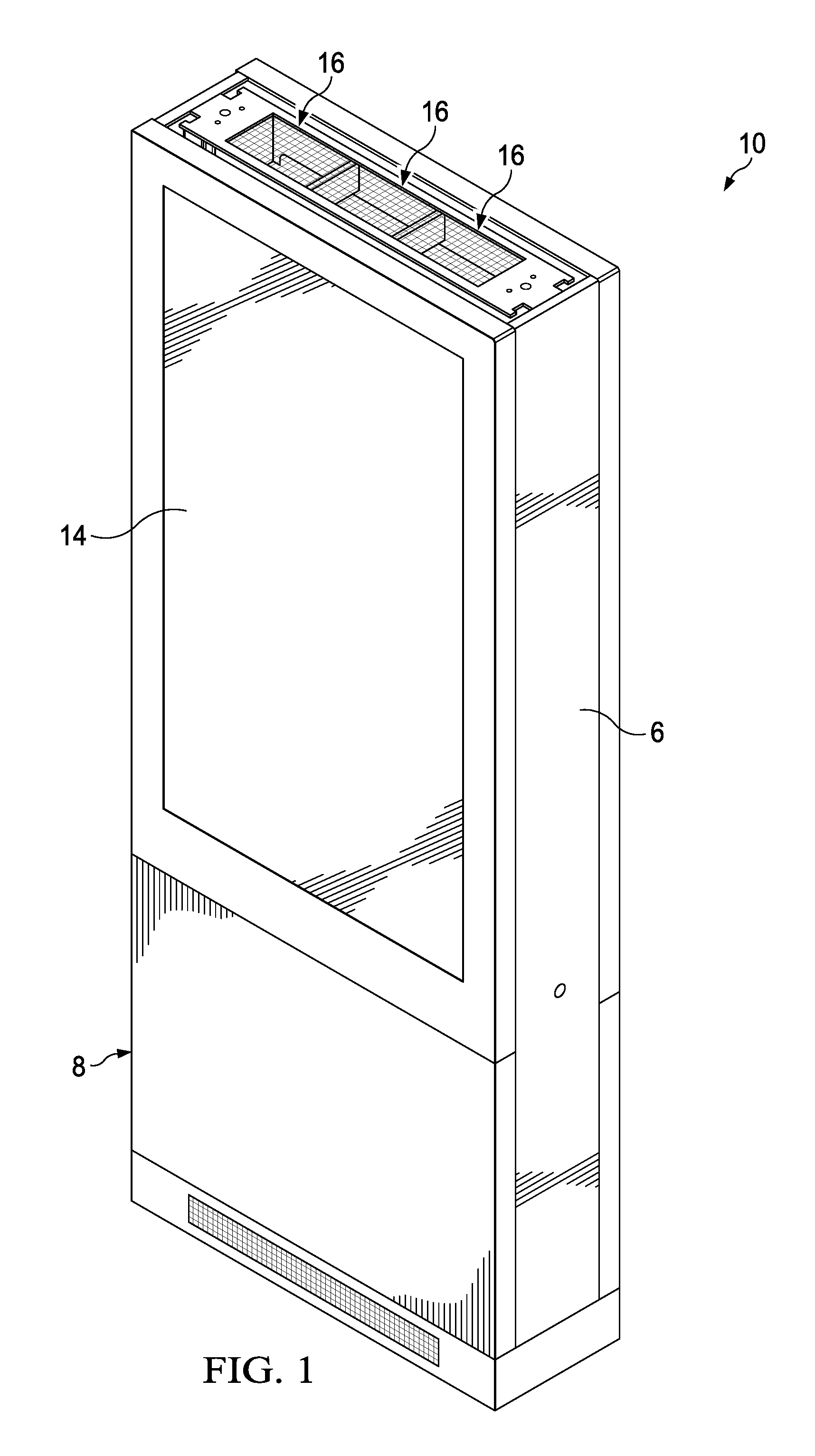
FIG. 1 is a front perspective view of an exemplary assembly in accordance with the present invention;
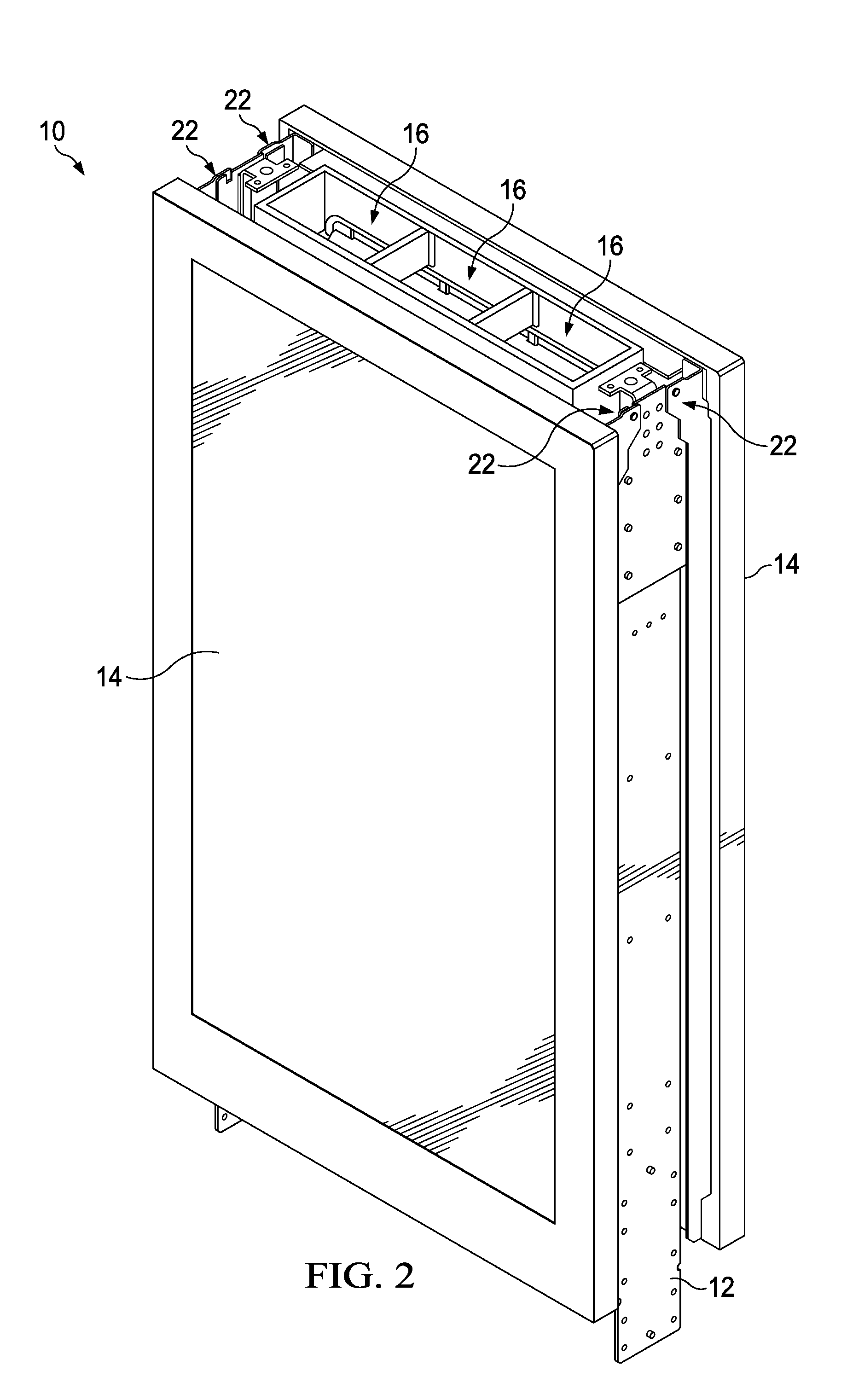
FIG. 2 is a front perspective of the assembly of FIG. 1 illustrated with the stand removed to illustrate additional components of the assembly;
FIG. 3 is a front perspective of the assembly of FIG. 2 illustrated with one of the assemblies in the open position;
FIG. 4 is a front perspective view of the assembly of FIG. 2 illustrated with one of the assemblies removed;
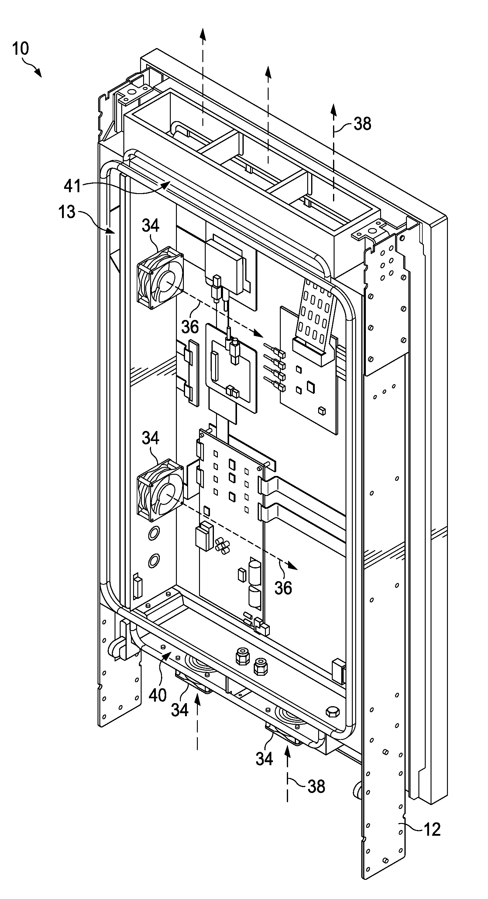
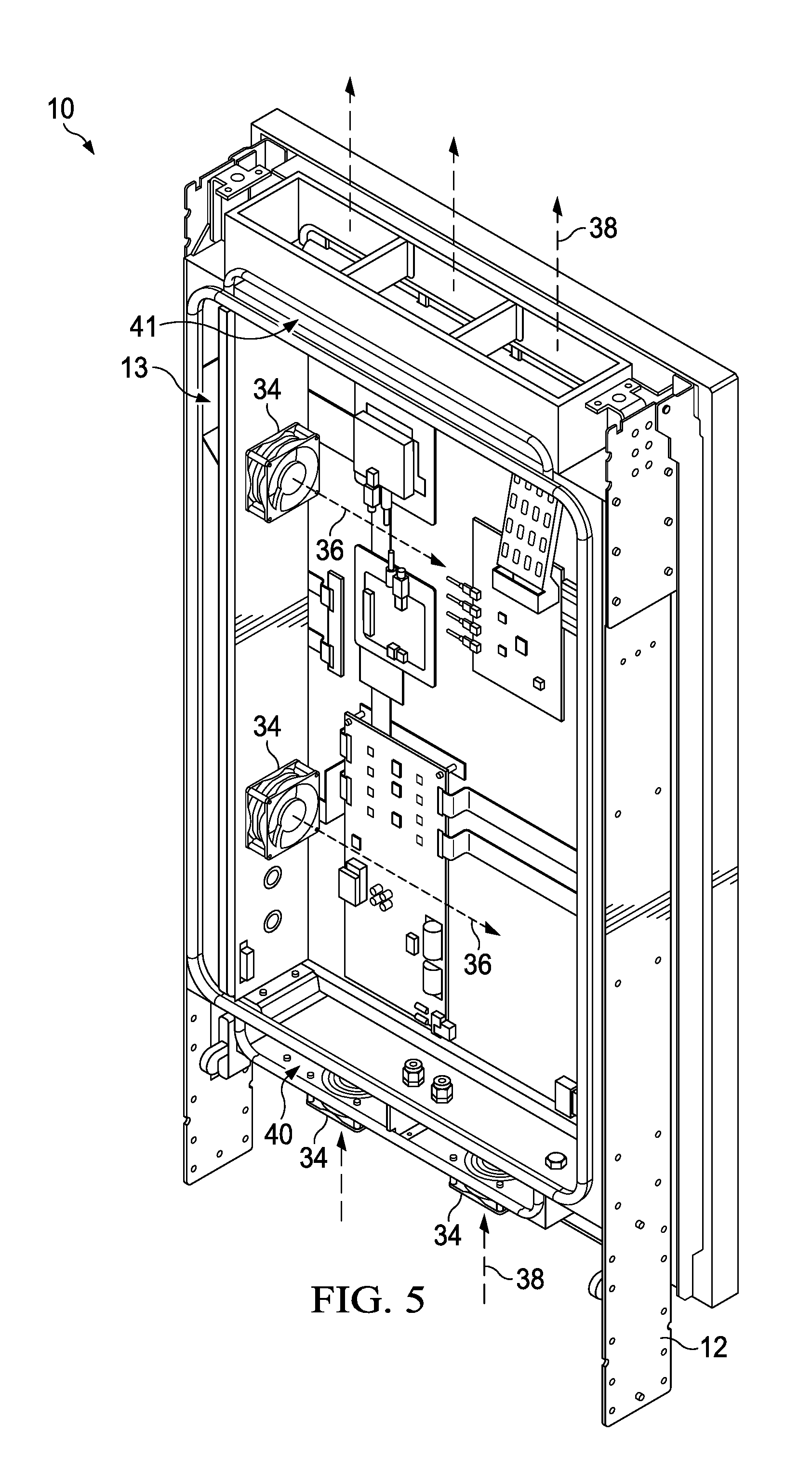
FIG. 5 is a front perspective view of the assembly of FIG. 4, illustrated with exemplary flow paths for circulating gas and ambient air;
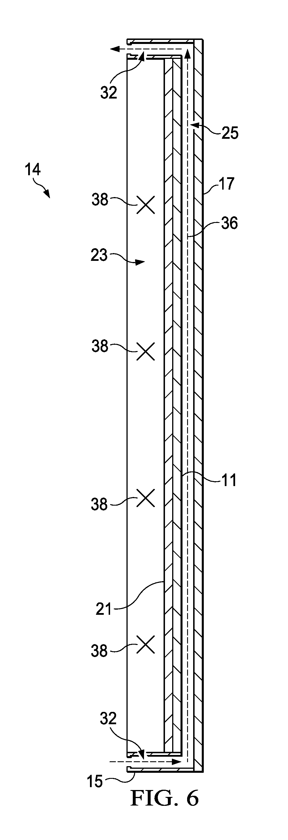
FIG. 6 is a top sectional view of an exemplary display assembly illustrated in isolation from other components to illustrate exemplary flow paths for circulating gas and ambient air;
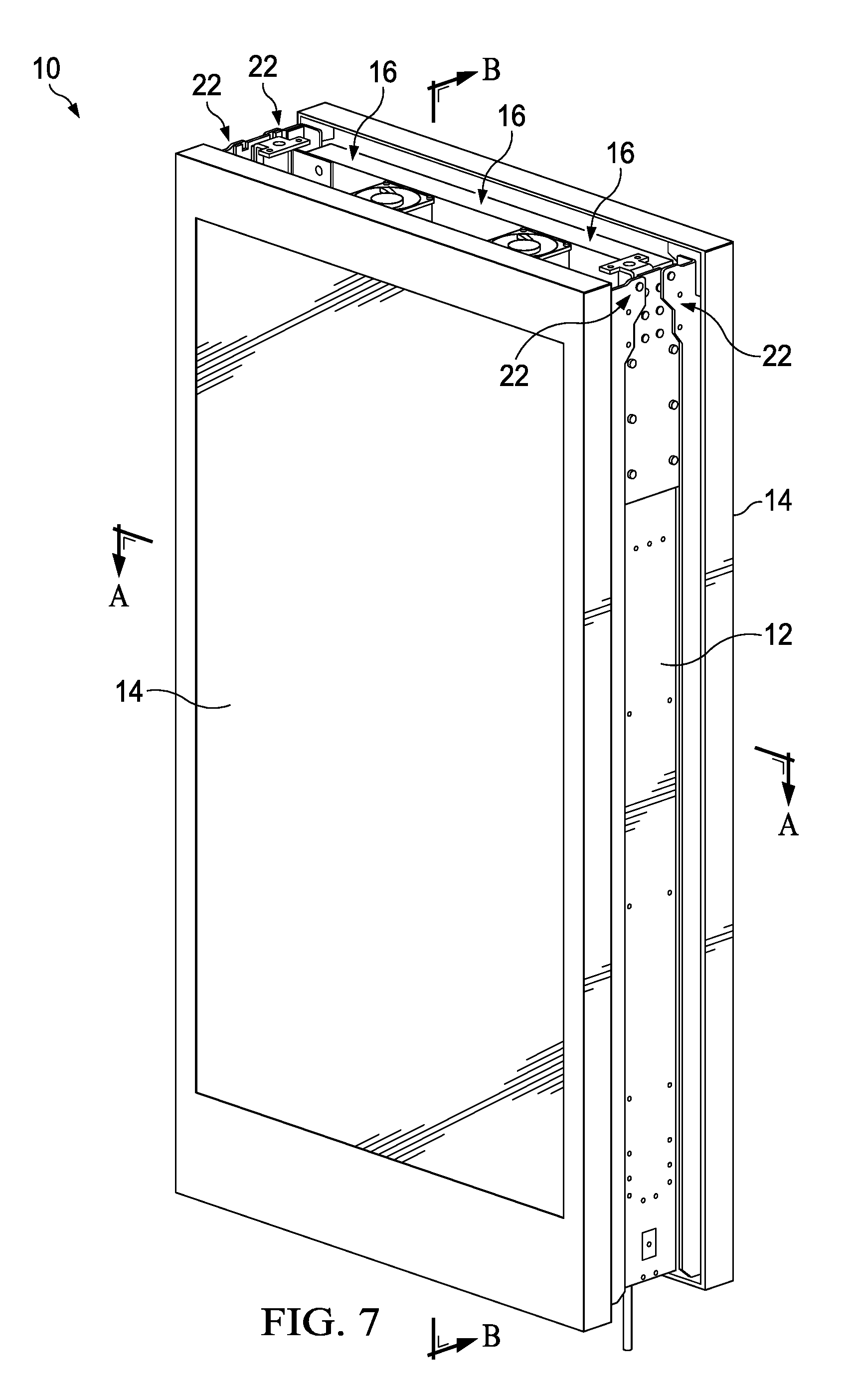
FIG. 7 is a front perspective view of another exemplary embodiment of the assembly also indicating section lines A-A and B-B;
FIG. 8 is a front perspective view of the assembly of FIG. 7 illustrated with both display assemblies in the open position;
FIG. 9 is an exploded front perspective view of the assembly of FIG. 8;
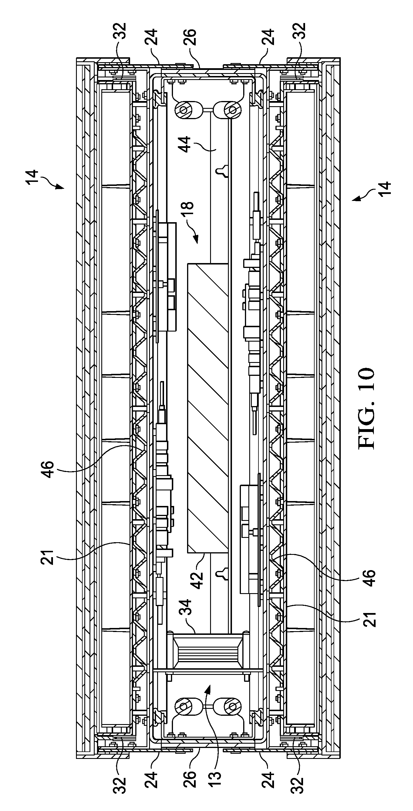
FIG. 10 is a top sectional view taken along section line A-A of FIG. 7;
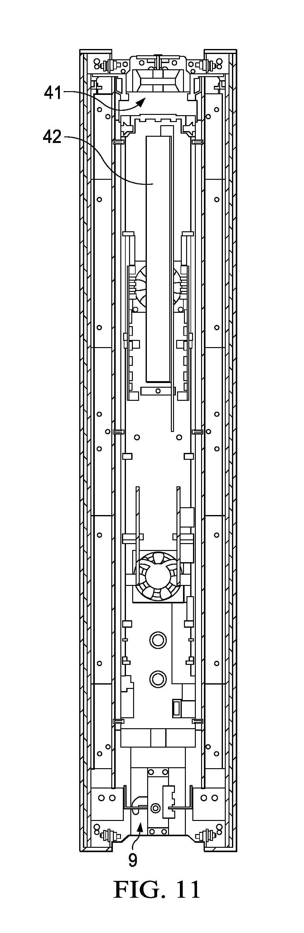
FIG. 11 is a side sectional view taken along section line B-B of FIG. 7;
FIG. 12A is a rear perspective view of another exemplary assembly;
FIG. 12B is a rear perspective view of another exemplary assembly;
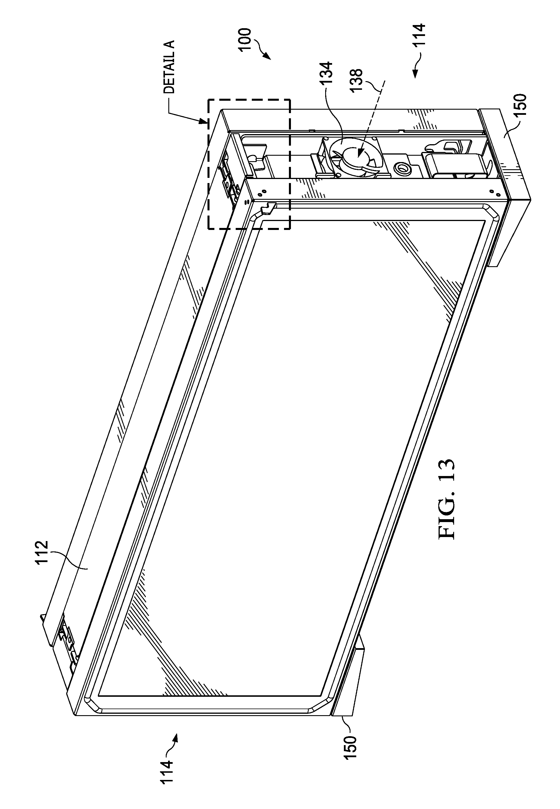
FIG. 13 is a front perspective view of another exemplary assembly also indicating Detail A;
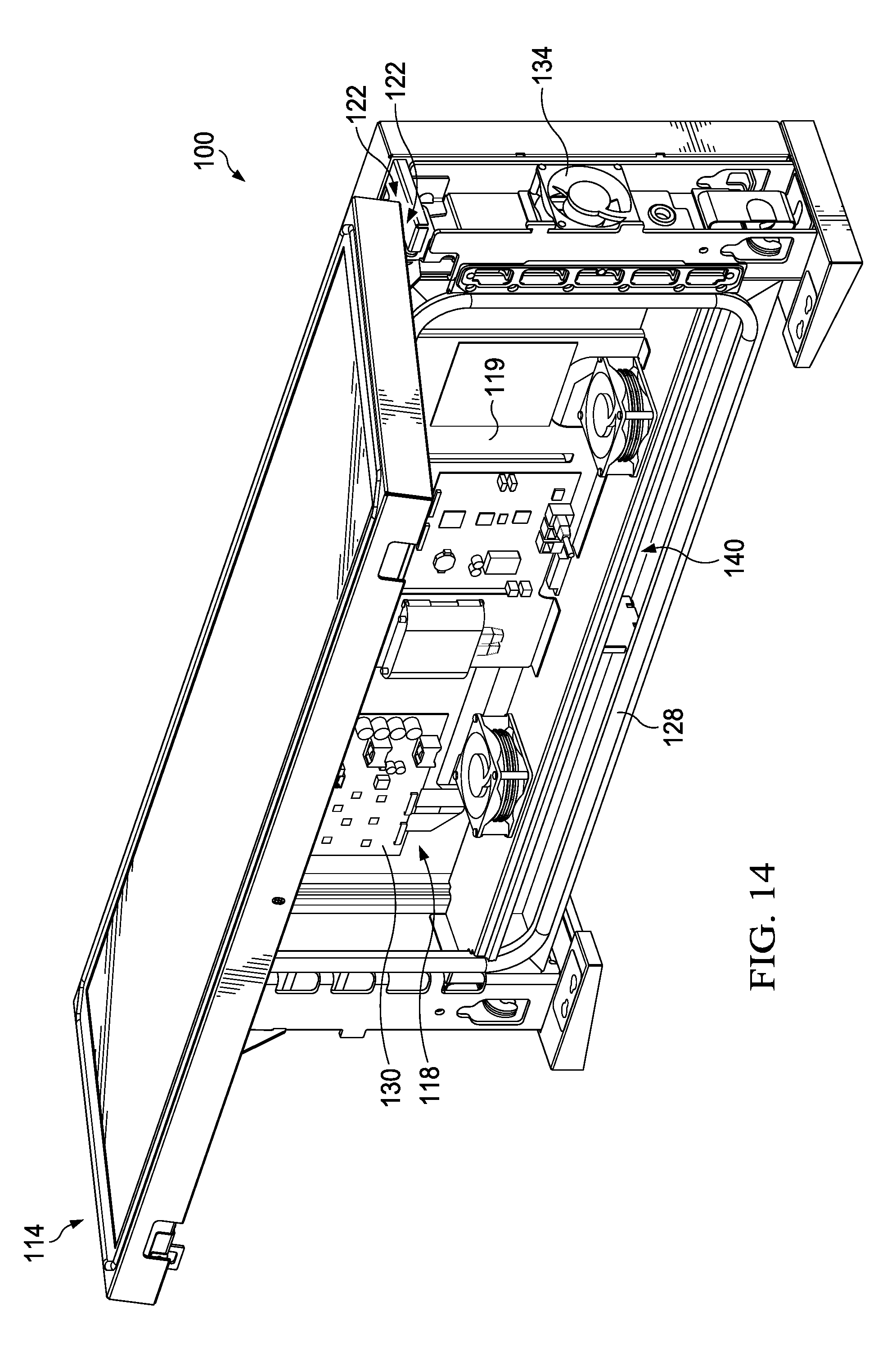
FIG. 14 is a front perspective view of the assembly of FIG. 13 illustrated with one of the display assemblies in the open position;
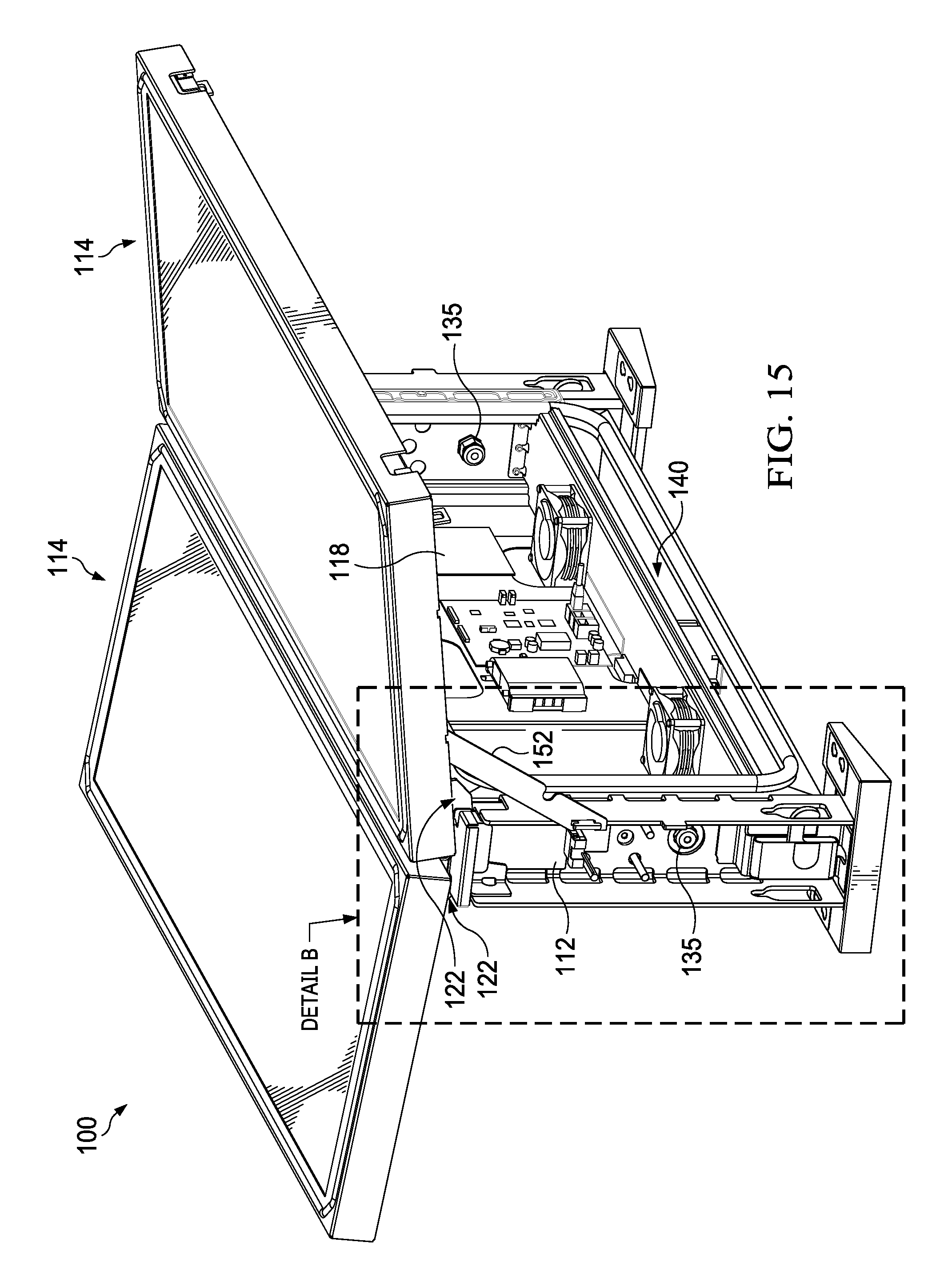
FIG. 15 is a rear perspective view of the assembly of FIG. 13 illustrated with both of the display assemblies in the open position also indicating Detail B;
FIG. 16 is a front perspective view of the assembly of FIG. 14 illustrated with one of the display assemblies removed;
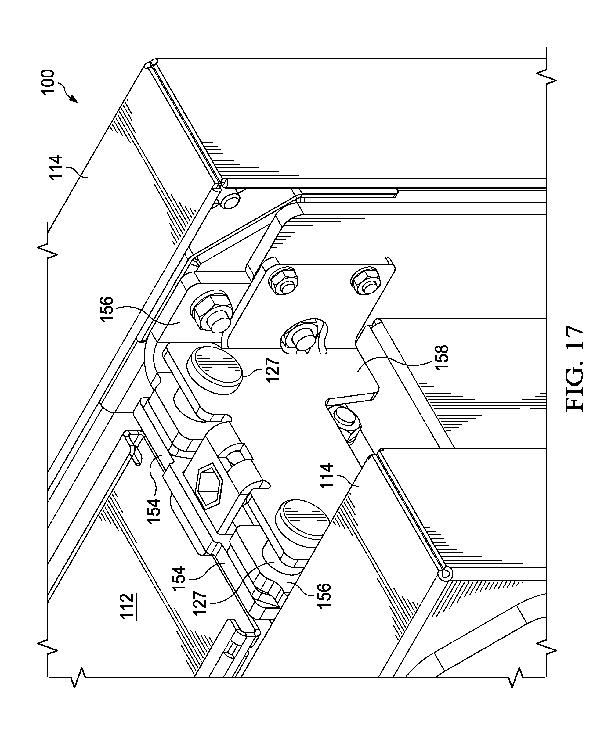
FIG. 17 is a detailed top perspective view of Detail A of FIG. 13;
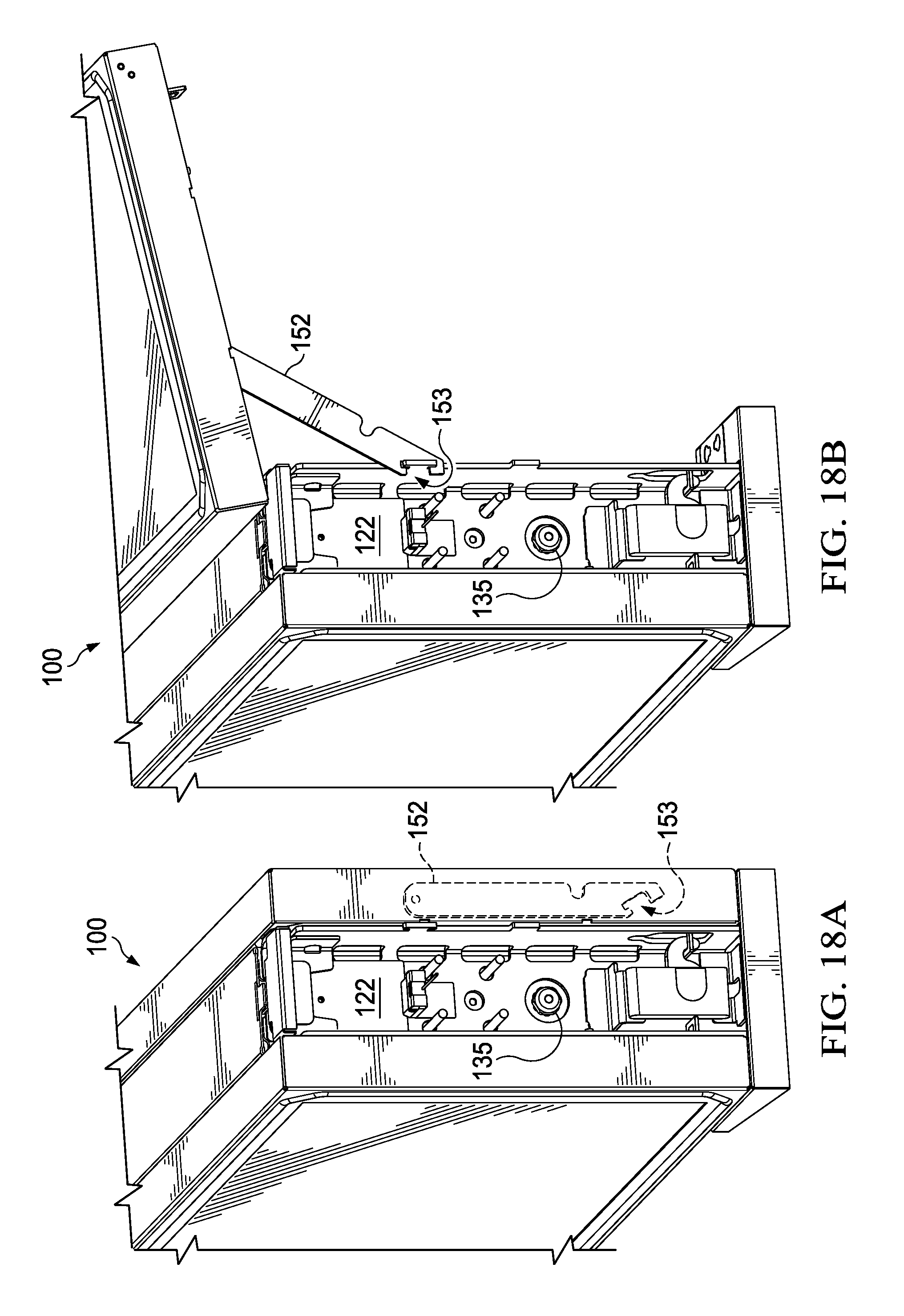
FIG. 18A is a detailed perspective view of Detail B of FIG. 15 with the display assembly in the closed position and illustrating an otherwise hidden strut; and
FIG. 18B is a detailed top perspective view of the assembly of FIG. 18A illustrated with the display assembly in the open position.
DETAILED DESCRIPTION OF EXEMPLARY EMBODIMENT(S)
Various embodiments of the present invention will now be described in detail with reference to the accompanying drawings. In the following description, specific details such as detailed configuration and components are merely provided to assist the overall understanding of these embodiments of the present invention. Therefore, it should be apparent to those skilled in the art that various changes and modifications of the embodiments described herein can be made without departing from the scope and spirit of the present invention. In addition, descriptions of well-known functions and constructions are omitted for clarity and conciseness.
FIG. 1 is a front perspective view of an exemplary assembly 10 in accordance with the present invention. The assembly 10 may comprise one or more display assemblies 14 placed within a housing 6. The housing 6 may comprise a stand 8 for mounting the assembly 10 to the ground. However, in other exemplary embodiments, the assembly 10 may be mounted to another object such as, but not limited to, a bus shelter, a post, a wall, a building, or the like. Regardless, an intake 16 may be located on the top of the housing 6. As will be described in greater detail herein, an exhaust 9 may be located on the bottom of the housing 6. However, it is contemplated that the intake 16 may be located on the bottom of the housing 6 with the exhaust 9 being located on the top of the housing 6.
FIG. 2 is a front perspective of the assembly 10 of FIG. 1 illustrated with the stand 6 removed to illustrate additional components of the assembly 10. The display assemblies 14 may be mounted to a frame 12. The frame 12 may be substantially rectangular in shape and may have interior and exterior surfaces or panels. In exemplary embodiments, the assembly 10 may comprise a single display assembly 14 mounted to the frame 12. In such embodiments, an access panel 48 may be mounted to the opposite side of the frame 12. As will be explained in greater detail herein, in exemplary embodiments the access panel 48 may be configured to receive a static poster. In other exemplary embodiments, the assembly 10 may comprise a first and a second display assembly 14 placed back-to-back on either side of the frame 12. Regardless, the frame 12 may be configured to be connected to the stand 8, another object, or directly to the ground.
As will be explained in greater detail herein, the assembly 10 may further comprise an electronics cavity 18 for storing electronic components 30 for operating the assembly 10. In the exemplary embodiments comprising the single display assembly 14, the electronics cavity 18 may located in the space between the display assembly 14, the frame 12, and the access panel 48. In other exemplary embodiments comprising the first and second display assemblies 14 placed back-to-back, the electronics cavity 18 may be located in the space between the display assemblies 14 and the frame 12. The first and second display assemblies 14 may share a common electronics cavity 18.
Regardless, the intake 16 may likewise extend through the frame 12. Similarly, the exhaust 9 may extend through the frame 12.
FIGS. 1 and 2 illustrate the display assemblies 14 in a closed position such that the display assemblies 14 are in contact with the frame 12 or are located substantially parallel to the ground. As will be explained in greater detail herein, the display assemblies 14 may be hingedly mounted to the frame 12 by way of a hinging device 22. A pair of hinging devices 22 may be located on either side of the frame 12. In the exemplary embodiments comprising the first and second display assemblies 14 located back-to-back, the same hinging devices 22 may be used to hingedly mount the first and the second display assemblies 14 to the frame 12, though such is not required. In exemplary embodiments, the hinging devices 22 may be located on an upper portion of the frame 12, though any location of the hinging devices 22 is contemplated.
FIG. 3 is a front perspective view of the assembly 10 of FIG. 2 illustrated with one of the display assemblies 14 in an open position. The display assembly 14 may rotate via the hinging device 22 into the opened position such that the bottom of the display assembly 14 is swung outwardly away from the frame 12. This may allow access to the electronics cavity 18 such that personnel may inspect, maintain, repair, replace, or otherwise service the electronic components 30 located therein.
The assembly 10 may further comprise a pair of aid devices 20, preferably having a first end and a second end, though such is not required. In exemplary embodiments, the aid devices 20 may be gas springs, though any type of aid device is contemplated. Such aid devices 20 may include, but are not limited to, any device which utilizes a mechanical advantage in order to assist is moving the display assemblies 14 between an open position or closed positions as well as, or alternatively, to temporarily secure the display assemblies 14 in the open position or closed position. Other exemplary aid devices 20 include, but are not limited to, struts, springs, block and tackle, counterweights, levers, gears, tethers, belts, chains, motors, screws, some combination thereof, or the like.
The first end of the aid devices 20 may be mounted to either side of the display assembly 14 and the second end of the aid devices 20 may be mounted to either side of the interior of the frame 12. In exemplary embodiments, the first end of the aid devices 20 is mounted lower relative to second end of the aid devices 20, though the opposite is contemplated. The aid devices 20 may be configured to assist with movement of the display assemblies 14 between the open and the closed positions as well as temporarily securing the display assemblies 14 in the opened or the closed positions.
In exemplary embodiments, the display assemblies 14 may be lockable to the frame 12 or the housing 6 such that the display assemblies 14 cannot normally be moved from the closed position unless unlocked. This may assist in restricting access to the electronics cavity 18 to authorized personnel.
For clarity, in exemplary embodiments where back-to-back display assemblies 14 are used, each of the first and the second display assembly 14 may comprise a first and second aid device 20 such that each of the display assemblies 14 may be moved between, or selectively secure in, the opened and the closed position. In exemplary embodiments where a single display assembly 14 is used, the display assembly 14 may comprise the first and second aid devices 20 such that the display assembly 14 may be moved between, or be selectively secured in, the opened and the closed position. In such embodiments, the access panel 48 may form the rear surface of the assembly 10 and may be swung outwardly and/or upwardly to allow access to the electronics cavity 18 as described in greater detail herein, though any direction of rotation or movement is contemplated.
FIG. 4 is a front perspective view of the assembly 10 of FIG. 2 illustrated with one of the display assemblies 14 removed so as to illustrate the electronics cavity 18. A gasket 28 may extend around the perimeter of either side of the frame 12. In exemplary embodiments where the first and second display assemblies 14 are placed back to back, the gaskets 28 may provide a substantially air tight seal when the display assemblies 14 are placed in the closed position. In exemplary embodiments where a single display assembly 14 is used, the gaskets 28 may provide a substantially air tight seal when the display assembly 14 and the access panel 48 are placed in the closed position. Regardless, this may allow the electronics cavity 18 to be sealed substantially air tight, though such is not required.
A plate 19 may be located in the electronics cavity 18 and the electronic components 30 may be mounted thereto. In exemplary embodiments, the plate 19 may be mounted to the frame 12 such that the plate 19 extends substantially parallel to the front surface of the electronic display assemblies 14 when the electronic display assemblies 14 are located in the closed position. Stated another way, the plate 19 may extend substantially perpendicular to the ground.
The electronic components 30 may comprise any number of components used to operate the assembly 10 and its various components. Such electronic components 30 may include, but are not limited to, power sources, power distribution components, video players, video receiver boards, processors, electronic storage devices, communications equipment, wireless transmitter/receivers, network connectivity devices, printed circuit boards, and the like. In exemplary embodiments, a number of the electronic components 30 may be utilized to operate both display assemblies 14 (in the embodiments where two display assemblies 14 are used). For example, but not to serve as a limitation, at least the video players, video receiver boards, communications equipment, wireless transmitter/receivers, and network connectivity devices may be shared. This may reduce the number of electronic components 30 required. In exemplary embodiments, the plate 19 may be a server rack, though such is not required.
The hinging device 22 may comprise a frame hinge plate 26 and a display hinge plate 24. The frame hinge plate 26 may be located on the exterior panels on either side of an upper portion of the frame 12 such that the frame hinge plate 26 extends substantially perpendicular relative to the plate 19. The frame hinge plate 26 may comprise one or more notches or apertures for mounting the display hinge plate 24 thereto. The display hinge plate 24 may be located on either side of an upper portion of the display assembly 14 such that the display hinge plate 26 extends substantially perpendicular relative to the plate 19. The display hinge plate 24 may comprise one or more notches or apertures corresponding to the notches or apertures located in the frame hinge plate 26. Any number of fasteners 27 may extend through the corresponding notches or apertures in the display hinge plate 24 and the frame hinge plate 26 such that the frame hinge plate 26 may be hingedly secured to the display hinge plate 24. The fasteners 27 may include a threaded fastener, pin, or the like. This is merely exemplary, any type of hinge device 22 is contemplated.
The design of the hinge device 22 may provide for easy removal of one or both of the display assemblies 14 when performing inspections, maintenance, repairs, replacements, or otherwise servicing the assembly 10. The fasteners 27 may simply be removed from either side of the display assembly 14 and the entire display assembly 14 may be removed. A replacement display assembly 14 may then be installed. The display assembly 14 being inspected, maintained, repaired, replaced, or otherwise serviced may then be returned to a service center for servicing. This may minimize downtime of the assembly 10.
FIG. 5 illustrates exemplary flow paths through the assembly 10 of FIG. 4. FIG. 6 illustrates a top sectional view of an exemplary display assembly 14 to further illustrate said exemplary flow paths. Each display assembly 14 may comprise a cover panel 17 that faces an intended viewer. An electronic display 11 may be located behind, spaced apart from, and substantially parallel to the cover panel 17. Cover panel 17 may be comprised of any substantially transparent or translucent material and may be comprised of multiple layers. The electronic display 11 may be any type of electronic display 11, including but not limited to, a liquid crystal display (LCD), light emitting diode (LED) display, organic LED (OLED) display, plasma display, or the like. The space between the rear surface of the cover panel 17 and the front surface of the electronic display 11 may define a first channel 25. A display assembly housing 15 may surround the electronic display 11 such that the combination of the cover panel 17 and the display assembly housing 15 substantially encloses the electronic display 11. One or more of the display assemblies 14 may further configured to receive touch input. For example, without limitation, the electronic display 11 may be a capacitive or resistive touch screen, though any type of touch screen is contemplated.
A backlight 21 may be located behind and substantially parallel to the electronic display 11. The backlight 21 may be spaced apart from the electronic display 11, though such is not required. A second channel 23 may be located within the display assembly 14 and may be configured to receive ambient air 38. The second channel 23 may permit ambient air 38 to flow vertically through the display assembly 14. In exemplary embodiments, the second channel 23 is defined, at least in part, by the space between the rear surface of the backlight 21 and the rear surface of the display assembly housing 15, though any location is contemplated.
A first and a second side channel 32 may extend along either side of the display assembly 14. The side channels 32 may be configured to receive circulating gas 36. In exemplary embodiments, the side channels 32 are defined, at least in part, by the space between the second channel 23 and the side of the display assembly housing 15, though any location is contemplated.
One or both sides of the frame 12 may comprise a side gap 13 located between interior and exterior side panels. As such, the assembly 10 may comprise a first and a second side gap 13, where each is located on either side of the frame 12. In other exemplary embodiments, the assembly 10 may comprise only a first side gap 13. Apertures may be located along the interior panels of the side(s) of the frame 12 having the side gap(s) 13 such that circulating gas 36 may be passed from the electronics cavity 12 into and out of the side gap(s) 13. In exemplary embodiments, the circulating gas 36 may flow from the first side gap 13 though the first side channel 32, though the first channel 25, through the second side channel 32, through the second side gap 13, though the electronics cavity 18, and be returned to the first side gap 13, thereby forming a closed loop. In exemplary embodiments where the assembly 10 comprises only the first side gap 13, the circulating gas 36 may pass directly from the electronics cavity 18 into or out of the first or the second side channel 32. Additionally, in exemplary embodiments where two display assemblies 14 are placed back-to-back, the circulating gas 36 may be split and travel through first channel 25 located in each respective display assembly 14. Side gaps 13 are not required.
One or more fans 34 may be mounted to said apertures in the interior panels of the side of the frame 12 to force the circulating gas 36 though the closed loop, though it is contemplated that any number of fans 34 may be placed at any number of locations along the path of the circulating gas 36.
The bottom and top of the frame 12 may similarly comprise interior and exterior panels with an upper gap 41 and a lower gap 40 located therebetween, though such is not required. Apertures may be located along the exterior panels of the bottom and top of the frame 12 such that ambient air 38 may be ingested from outside of the assembly 10 and exhausted from inside of the assembly 10. These apertures may form the exhaust 9 and the intake 16. In exemplary embodiments, ambient air 38 may be ingested from the bottom of the assembly 10 into the lower gap 40. The ambient air 38 may then travel vertically upwards through the second channel 23 in the display assembly 14 and into the upper gap 41. The ambient air 38 may then be exhausted through the intake 16, thus forming an open loop. In the exemplary embodiments where the first and the second display assemblies 14 are placed back-to-back, the ambient air 38 may be split and travel through each of the channels 23 located in each of the respective display assemblies 14.
One or more fans 34 may be mounted to said apertures in the exterior panels of the bottom of the frame 12 to force the ambient air 38 though the open loop, though it is contemplated that any number of fans 34 may be located in any number of locations along the path of the ambient air 38.
The ambient air 38 flowing through the second channel 23 may be in thermal communication with the backlight 21 so as to absorb heat generated therefrom, though such is not required. The ambient air 38 flowing through the second channel 23 may be in thermal communication with circulating gas 36 flowing through the closed loop such that the relatively cool ambient air 38 may remove heat from the relatively warm circulating gas 36. The ambient air 38 flowing through the open loop may be in thermal communication with the circulating gas 32 flowing through the closed loop so as to absorb heat therefrom while not allowing the ambient air 38 and the circulating gas 32 to substantially mix.
FIG. 7 is a front perspective view similar to FIG. 1 of another exemplary embodiment of the assembly 10 also indicating section lines A-A and B-B.
FIG. 8 is a front perspective view of the assembly 10 of FIG. 7 illustrated with both display assemblies 14 in the open position. The plate 19 may be mounted to one of the display assemblies 14. In other exemplary embodiments, the plate 19 may form a part of the display assembly 14. Many or all of the electronic components 30 may still be shared by the display assemblies 14.
FIG. 9 is a front perspective exploded view of the assembly of FIG. 8. A second plate 42 may be mounted to the frame 12, though such is not required. The second plate 42 may be located an upper portion of the electronics cavity 18, though any location is contemplated. The second plate 42 may be mounted to extend parallel to the front surface of the electronic display assemblies 14 when the electronic display assemblies 14 are in the closed position. The second plate 42 may be configured to receive additional electronic components 44, which may be mounted thereto. In exemplary embodiments, the additional electronic components 44 may comprise customer-specific or customer-installed electronic components or components to operate the assembly 10. However, any type of electronic components 44 are contemplated, such as but not limited to, computers, processors, routers, servers, machine to machine communications equipment, wireless connectivity devices, Bluetooth connectivity devices, near field communication devices, cameras, electronic storage devices, memory, and the like. In exemplary embodiments, the second plate 42 may be a server rack, such as but not limited to, a 1U server rack.
By placing the display assemblies 14 in the opened position, the elections cavity 18, the plate 19, the second plate 42, the related electronic components 30 and additional electronic components 44 may be maintained, repaired, replaced, or otherwise serviced. Additionally, the display assemblies 14 themselves may by maintained, repaired, replaced, or otherwise serviced by removing the display assemblies from the hinging device 22 as previously discussed.
Various pass through devices 35 may be located in the walls defining the cavity 18 such that power lines, communication lines, and the like may be passed into the cavity 18 from outside. The pass through devices 35 may be configured to provide a substantially air and water tight seal. Any number and location of said pass through devices 35 are contemplated. This may help to reduce the number of pass through points in the assembly 10 and simplify the cabling. The cavity 18 may provide a substantially sealed, cooled, connected, and/or powered electronics cavity 18 for mounting electronic components, such as but not limited to, the additional electronic components 44 and the electronic components 30.
FIG. 9 illustrates an exemplary assembly 10 where the fans 24 for the ambient air 38 may be located on the top of the frame 12 in the apertures of the upper gap 41.
FIG. 10 is a top sectional view taken along section line A-A of FIG. 7 and illustrating the display assemblies 14 in the closed position. The second channel 23 may comprise a corrugation layer 46 located between the backlight 21 and the electronics cavity 18. The ambient air 38 may pass through the corrugation layer 46. As illustrated in FIG. 10, the assembly 10 may only comprise the first side gap 13. It is contemplated that the first side gap 13 may be located on either side of the assembly 10 or may not be required at all.
FIG. 11 is a side sectional view taken along section line B-B of FIG. 7. As illustrated in FIG. 11, the lower gap 40 is optional. Instead, ambient air 38 may enter via the exhaust 9 and be ingested directly into the display assemblies 14 where it may travel through the second channel 23 to the upper gap 41 and exit via the intake 16.
FIG. 12A and FIG. 12B is a rear perspective view of another exemplary assembly 10. FIGS. 12A-12B illustrates an exemplary assembly 10 having a single display assembly 14 and further comprising the access panel 48 located on the rear of the frame 12. The access panel 48 may be a door, though any type of access panel 48 is contemplated. The access panel 48 may be comprised of sheet metal, though any material is contemplated. In other exemplary embodiments, the access panel 48 may be configured to hold a static poster. For example, without limitation, the access panel 48 may comprise a transparent cover located above the door to define a poster cavity configured hold the poster such that it may be located therebetween. In yet another example, without limitation, edge lighting may be placed at various locations around said poster to illuminate the poster.
In exemplary embodiments the access panel 48 may swing open horizontally (as shown in FIG. 12A) or vertically (as shown in FIG. 12B). In exemplary embodiments where the access panel 48 swings open vertically, aid devices 20 may likewise be used to assist in moving the access panel 48 between the open and closed positions as well as securing the access panel 48 in the open and closed positions. The access panel 48 may be lockable to the frame 12 or the housing 6 such that the access panel 48 cannot normally be moved from the closed position unless unlocked. This may assist in restricting access to the electronics cavity 18 to authorized personnel.
In exemplary embodiments, the plate 19 may be mounted to the access panel 48. In still other exemplary embodiments, the access panel 48 may be the plate 19.
Although the flow of the ambient air 38 and the circulating gas 36 may be shown and described herein with respect to particular directions and orientations, it is contemplated that the ambient air 38 and the circulating gas 36 may flow in other directions. For example, without limitation, ambient air 38 and circulating gas 36 shown as flowing clockwise may flow counter-clockwise, when shown flowing vertically from top to bottom may flow from bottom to top, when shown flowing horizontally from right to left may flow from left to right, when shown flowing vertically may flow horizontally, when shown flowing horizontally may flow vertically, and the like.
It is contemplated that the assembly 10, or various components thereof, may be adapted for and/or used with any size display assemblies 14 in any application. For example, but not to serve as a limitation, the assembly 10, or various components thereof, may be adapted for and/or used with a vehicle topper unit such as is illustrated and described in U.S. patent application Ser. No. 15/450,365 filed Mar. 6, 2017, the disclosures of which are hereby incorporated by reference in their entirety.
FIG. 13 is a front perspective view of another exemplary assembly 100 also indicating Detail A. FIG. 13 through FIG. 18B illustrate and describe an adaptation of the assembly 10 for use with a vehicle topper unit as previously mentioned. Similar features have been similarly numbered but increased by 100 (e.g., assembly 10 and assembly 100). The assembly 100 may comprise a frame 112 which may be rectangular in shape, though any shape is contemplated. The frame 112 may be covered by cladding that forms a housing. The cladding may provide an aesthetically pleasing appearance and may improve aerodynamics. The frame 112 may be adapted to be mounted to the roof of a vehicle, though such is not required. A first and second display assembly 114 may be attached to the frame 112, though any number of display assemblies 114 are contemplated. In exemplary embodiments, the first and second display assemblies 114 are placed back-to-back on either side of the frame 112. The assembly 100 may further comprise a pair of mounting devices 150. In exemplary embodiments, the mounting devices 150 may be located on the underside of the frame 112 and may be feet configured to permit the assembly 100 to be mounted to the roof of a vehicle, though any type of mounting device 150 is contemplated.
A fan 134 may be located on an aperture in the frame 112 to permit the ingestion of ambient air 138. Once ingested, the ambient air 138 may travel horizontally through channels in the display assemblies 114 and exit through apertures on the other end of the frame 112. This may form an open loop. It is contemplated that the fan 134 may be located at any location along the path of the ambient air 138.
FIG. 14 is a front perspective view of the assembly 100 of FIG. 13 illustrated with one of the display assemblies 114 in the open position. The display assemblies 114 may be hingedly mounted to the frame 112 by way of a hinging device 122. The hinging device 122 may permit the display assemblies 114 to be moved between a closed position, wherein the respective display assembly 114 rests against the frame 112 and/or where the front surface of the respective display assembly 114 is substantially perpendicular to the ground, and an open position wherein the respective display assembly 114 is rotated outwardly from the frame 112 and/or where the front surface of the respective display assembly 114 is substantially parallel to the ground. A gasket 128 may extend around the perimeter of the surfaces of the frame 112 which contact the display assemblies 114. The gaskets 128 may provide a substantially air tight seal in the electronics cavity 118 when the display assemblies 114 are located in the closed position.
An electronics cavity 118 may be located between the rear surfaces of the display assemblies 114. The electronics cavity 118 may comprise a plate 119 that is configured to receive a number of electronic components 130 or additional electronic components 144 which may be mounted thereto. In exemplary embodiments, the plate 119 may be mounted to the frame 112. In other exemplary embodiments, the plate 119 may be mounted to, or form a part of, one of the display assemblies 114. Various pass through devices 135 may be located in the walls defining the cavity 118 such that power lines, communication lines, and the like may be passed into the cavity 118 from outside. The pass through devices 135 may be configured to provide a substantially air and water tight seal. This may help to reduce the number of pass through points in the assembly 100 and simplify the cabling. In exemplary embodiments, the electronics cavity 118 may provide a cooled, powered, connected, and/or sealed area for electronic components, such as but not limited to, the electronic components 130 and the additional electronic components 144.
When either or both the of display assemblies 114 are placed in the open position, the electronics cavity 118 may be exposed. This may allow access to the electronics cavity 118, the plate 119, and the electronic components 130 such that personnel may inspect, maintain, repair, replace, or otherwise service the electronic components 130 located therein. In exemplary embodiments, the display assemblies 114 may be selectively locked to the frame 112 such that the respective display assembly 114 cannot normally be moved from the closed position unless unlocked. This may assist in restricting access to the electronics cavity 118 to authorized personnel.
The frame 112 may comprise interior and exterior surfaces. In exemplary embodiments, a lower gap 140 may be located in the space between the interior and exterior surfaces of the frame 112 along a lower portion thereof. Stated another way, the lower gap 140 may be located between the bottom of the electronics cavity 118 and the bottom of the frame 112.
FIG. 15 is a rear perspective view of the assembly 100 of FIG. 13 illustrated with both of the display assemblies 114 in the open position and also indicating Detail B. A first and second strut 152 may extend between the frame 112 and each of the respective display assemblies 114. In other exemplary embodiments, a pair of struts 152 may be used for each respective display assembly 114. The strut 152 may be configured to temporarily secure the respective display assembly 114 in the opened position, although it is contemplated that the strut 152 may be configured to also temporarily secure the respective display assembly 114 in the closed position. Alternatively, any of the aid devices 20 may be utilized in conjunction with or in substitution of the struts 152.
In exemplary embodiments, the struts 152 may be mounted to each of the respective display assemblies 114 in a rotatable fashion. The strut 152 may be mounted in a rotatable fashion by way of a pin or a fastener, though any device or mounting configuration is contemplated. Regardless, the struts 152 may be configured to be temporarily secured to each of the respective display assemblies 114 such that the respective display assembly 114 is propped or otherwise held in the open position. While the struts 152 are discussed as being mounted to each of the respective display assemblies 114 and temporarily secured to the frame 112, it is contemplated that the struts 152 may instead be mounted to frame 112 and temporarily secured to each of the respective display assemblies 114.
FIG. 16 is a front perspective view of the assembly 100 of FIG. 14 illustrated with one of the display assemblies 114 removed. Circulating gas 136 may travel vertically through the electronics cavity 118 where it is separated and passes through each respective display assembly 114. In exemplary embodiments, the circulating gas 136 flows through a channel between a cover glass an electronic display in each of the respective display assemblies 114. The circulating gas 136 may then travel through the lower gap 140 and be returned to the electronics cavity 118 via apertures in the interior surfaces of the frame 112, thereby forming a closed loop. In exemplary embodiments, these apertures in the frame 112 may have fans 134 mounted thereto to move the circulating gas 136 through the closed loop, though it is contemplated that the fans 134 may be located anywhere along the path of the circulating gas 136.
U.S. patent application Ser. No. 15/450,365 filed Mar. 6, 2017, the disclosures of which are hereby incorporated by reference in their entirety, describes an exemplary thermal management system for the assembly 100 including, but not limited to, open and closed loop pathways for ambient air and circulating gas.
FIG. 17 is a detailed top perspective view of Detail A of FIG. 13. The hinging device 122 may comprise a first and second display hinge plate 156, a first frame hinge plate 154, and a second frame hinge plate 158. Each of the first and second display leaves 156 may be substantially "L" shaped and may be configured to extend between a rear surface of the respective display assemblies 114 and the first frame hinge plate 154. The first frame hinge plate 154 may be mounted to either end of the frame 112. Optionally, a second frame hinge plate 158 may be located on the other side of the first and second display leaves 156 such that the first and second display leaves 156 are sandwiched between the first frame hinge plate 154 and the second frame hinge plate 158. A first fastener 127 may extend through the first frame hinge plate 154, the first display hinge plate 156, and the second frame hinge plate 158. Likewise, a second fastener 127 may extend through the first frame hinge plate 154, the second display hinge plate 156, and the second frame hinge plate 158. The fastener 127 may be a pin or another device allowing for rotational movement of the first and second display leaves 156. In exemplary embodiments, the second frame hinge plate 158 may be selectively secured to the respective display assembly 114 such that the respective display assembly 114 may be temporarily secured in the closed position.
The design of the hinge device 122 may provide for easy removal of one or both of the display assemblies 114 when performing inspections, maintenance, repairs, replacements, or otherwise servicing the assembly 100. The fasteners 127 may simply be removed from either side of the respectively display assembly 114 and the entire display assembly 114 may be removed. A replacement display assembly 114 may then be installed. The display assembly 114 being inspected, maintained, repaired, replaced, or otherwise serviced may then be returned to a service center for servicing. This may minimize downtime of the assembly 100.
FIG. 18A is a detailed perspective view of Detail B of FIG. 15 also illustrating the otherwise hidden strut 152. FIG. 18B is a top perspective view of the assembly 100 of FIG. 18A illustrated with the display assembly 114 in the open position. As can be seen, the strut 152 may be moved between a supporting and a stored position. The strut 152 may rotated into the stored position such that the strut 152 is aligned with the display assembly 114 when the display assembly 114 in the closed position. In this way, the strut 152 may be stored within the respective display assembly 114 when the strut 152 is not being used to keep the display assembly 114 in the open position. The strut 152 may be rotated into the supporting position where the strut 152 is secured at an angle to the frame 112 such that the display assembly 114 is propped or otherwise held in the open position. In exemplary embodiments, the strut 152 may comprise a notch 153 configured to be temporarily secured to a corresponding bracket or groove located on the frame 112 so as to prop or hold the respective display assembly 114 in the open position.
Any embodiment of the present invention may include any of the optional or preferred features of the other embodiments of the present invention. The exemplary embodiments herein disclosed are not intended to be exhaustive or to unnecessarily limit the scope of the invention. The exemplary embodiments were chosen and described in order to explain the principles of the present invention so that others skilled in the art may practice the invention. Having shown and described exemplary embodiments of the present invention, those skilled in the art will realize that many variations and modifications may be made to the described invention. Many of those variations and modifications will provide the same result and fall within the spirit of the claimed invention. It is the intention, therefore, to limit the invention only as indicated by the scope of the claims.
* * * * *
D00000
D00001
D00002
D00003
D00004
D00005
D00006
D00007
D00008
D00009
D00010
D00011
D00012

D00013
D00014
D00015
D00016

D00017
D00018
XML
uspto.report is an independent third-party trademark research tool that is not affiliated, endorsed, or sponsored by the United States Patent and Trademark Office (USPTO) or any other governmental organization. The information provided by uspto.report is based on publicly available data at the time of writing and is intended for informational purposes only.
While we strive to provide accurate and up-to-date information, we do not guarantee the accuracy, completeness, reliability, or suitability of the information displayed on this site. The use of this site is at your own risk. Any reliance you place on such information is therefore strictly at your own risk.
All official trademark data, including owner information, should be verified by visiting the official USPTO website at www.uspto.gov. This site is not intended to replace professional legal advice and should not be used as a substitute for consulting with a legal professional who is knowledgeable about trademark law.