Air channel thermocomfort foam pad
Line , et al. Nov
U.S. patent number 10,479,243 [Application Number 15/832,577] was granted by the patent office on 2019-11-19 for air channel thermocomfort foam pad. This patent grant is currently assigned to Ford Global Technologies, LLC. The grantee listed for this patent is Ford Global Technologies, LLC. Invention is credited to Alan George Dry, Spencer Robert Hoernke, Johnathan Andrew Line.
| United States Patent | 10,479,243 |
| Line , et al. | November 19, 2019 |
Air channel thermocomfort foam pad
Abstract
A seat cushion assembly includes a first foam pad defining at least one air cooling column disposed therethrough. A topper pad is disposed over the first foam pad and the at least one air cooling column. A second foam pad is disposed below the first foam pad. The second foam pad and the first foam pad define a flow channel in fluid communication with the at least one air cooling column. An air mover moves air from an air intake of the flow channel to an air exhaust of the flow channel.
| Inventors: | Line; Johnathan Andrew (Northville, MI), Dry; Alan George (Grosse Pointe Woods, MI), Hoernke; Spencer Robert (Dundas, CA) | ||||||||||
|---|---|---|---|---|---|---|---|---|---|---|---|
| Applicant: |
|
||||||||||
| Assignee: | Ford Global Technologies, LLC
(Dearborn, MI) |
||||||||||
| Family ID: | 66137964 | ||||||||||
| Appl. No.: | 15/832,577 | ||||||||||
| Filed: | December 5, 2017 |
Prior Publication Data
| Document Identifier | Publication Date | |
|---|---|---|
| US 20190168647 A1 | Jun 6, 2019 | |
| Current U.S. Class: | 1/1 |
| Current CPC Class: | B60N 2/5642 (20130101); B60N 2/7017 (20130101); B60N 2/7094 (20130101); B60N 2/5657 (20130101) |
| Current International Class: | B60N 2/56 (20060101); B60N 2/70 (20060101) |
References Cited [Referenced By]
U.S. Patent Documents
| 5902014 | May 1999 | Dinkel et al. |
| 6079781 | June 2000 | Tilley |
| 6145925 | November 2000 | Eksin et al. |
| 6189966 | February 2001 | Faust et al. |
| 6196627 | March 2001 | Faust et al. |
| 6224150 | May 2001 | Eksin et al. |
| 6619737 | September 2003 | Kunkel et al. |
| 6682140 | January 2004 | Minuth et al. |
| 6736452 | May 2004 | Aoki et al. |
| 6808230 | October 2004 | Buss et al. |
| 6848742 | February 2005 | Aoki et al. |
| 6869140 | March 2005 | White et al. |
| 6988770 | January 2006 | Witchie |
| 7100978 | September 2006 | Ekern et al. |
| 7213876 | May 2007 | Stowe |
| 7229129 | June 2007 | White et al. |
| 7261371 | August 2007 | Thunissen et al. |
| 7425034 | September 2008 | Bajic et al. |
| 7467823 | December 2008 | Hartwich |
| 7478869 | January 2009 | Lazanja et al. |
| 7506924 | March 2009 | Bargheer et al. |
| 7506938 | March 2009 | Brennan et al. |
| 7510239 | March 2009 | Stowe |
| 7578552 | August 2009 | Bajic et al. |
| 7695062 | April 2010 | Stowe |
| 7735932 | June 2010 | Lazanja et al. |
| 7775602 | August 2010 | Lazanja et al. |
| 7794012 | September 2010 | Szablewski |
| 7802843 | September 2010 | Andersson et al. |
| 7862113 | January 2011 | Knoll |
| 7931330 | April 2011 | Itou et al. |
| 7963595 | June 2011 | Ito et al. |
| 7966835 | June 2011 | Petrovski |
| 7971931 | July 2011 | Lazanja et al. |
| 8038222 | October 2011 | Lein et al. |
| D655393 | March 2012 | Whitaker |
| 8162391 | April 2012 | Lazanja et al. |
| 8360517 | January 2013 | Lazanja et al. |
| 8516842 | August 2013 | Petrovski |
| 8678500 | March 2014 | Lem et al. |
| 8696067 | April 2014 | Galbreath et al. |
| 9096157 | August 2015 | Line et al. |
| 9272647 | March 2016 | Gawade et al. |
| 9320361 | April 2016 | Gaines et al. |
| 2002/0096915 | July 2002 | Haupt et al. |
| 2004/0195870 | October 2004 | Bohlender et al. |
| 2004/0265184 | December 2004 | Matsuda |
| 2005/0200166 | September 2005 | Noh |
| 2007/0120401 | May 2007 | Minuth et al. |
| 2007/0200398 | August 2007 | Wolas et al. |
| 2009/0033130 | February 2009 | Marquette et al. |
| 2009/0066122 | March 2009 | Minuth et al. |
| 2009/0090172 | April 2009 | Angelescu |
| 2009/0134677 | May 2009 | Maly |
| 2009/0152909 | June 2009 | Andersson |
| 2009/0322124 | December 2009 | Barkow et al. |
| 2010/0038937 | February 2010 | Andersson et al. |
| 2010/0327636 | December 2010 | Stoll et al. |
| 2011/0109127 | May 2011 | Park et al. |
| 2011/0109128 | May 2011 | Axakov et al. |
| 2011/0133525 | June 2011 | Oota |
| 2011/0186560 | August 2011 | Kennedy et al. |
| 2011/0248532 | October 2011 | Kim et al. |
| 2011/0260509 | October 2011 | Siu |
| 2012/0080911 | April 2012 | Brykalski et al. |
| 2012/0129440 | May 2012 | Kitaguchi et al. |
| 2012/0261974 | October 2012 | Yoshizawa et al. |
| 2012/0267937 | October 2012 | Sahashi |
| 2014/0152057 | June 2014 | Truant et al. |
| 2015/0118426 | April 2015 | Roberts |
| 2017/0210258 | July 2017 | Cheon |
| 2018/0022252 | January 2018 | Arata |
| 2019/0061573 | February 2019 | Dry |
| 19857386 | Jun 2000 | DE | |||
| 102006061226 | Jun 2008 | DE | |||
| 102010012212 | May 2012 | DE | |||
| 102012006074 | Nov 2012 | DE | |||
| 1050429 | Nov 2000 | EP | |||
| 1123834 | Aug 2001 | EP | |||
| 1266794 | Dec 2002 | EP | |||
| 2423040 | Feb 2012 | EP | |||
| 2011251573 | Dec 2011 | JP | |||
| 20080066428 | Jul 2008 | KR | |||
| 20110051692 | May 2011 | KR | |||
| 101180702 | Sep 2012 | KR | |||
| 2006131189 | Dec 2006 | WO | |||
| 2007028015 | Mar 2007 | WO | |||
Other References
|
Seat Comfort Systems, Installation Manual, Kit P/N: SCSOOOOOC3, http://www.techwebasto.com/accessories_main/seat_accessories/g_scs_vent_i- nstall.pdf, accessed Apr. 27, 2017, 7 pgs. cited by applicant . Mercedes-Benz, "Interior comfort--spoilt for choice", http://www.zungfu.com/pc_E_saloon.comfort.1.shtml, Feb. 28, 2013, 3 pgs. cited by applicant. |
Primary Examiner: Allred; David E
Attorney, Agent or Firm: Chea; Vichit Price Heneveld LLP
Claims
What is claimed is:
1. A seat cushion assembly comprising: a first foam pad defining, at least in part, at least two vertically elongate air cooling columns disposed therethrough; a topper pad disposed over the first foam pad and the at least two air cooling columns; a second foam pad disposed below the first foam pad, the second foam pad and the first foam pad defining a flow channel in fluid communication with the at least two air cooling columns; and an air mover moving air from an air intake of the flow channel to an air exhaust of the flow channel; wherein at least one of the first foam pad and the second foam pad comprises an L-shaped section and the other of the first foam pad and the second foam pad comprises a protruding portion section that together with the L-shaped section defines at least a portion of the flow channel that interconnects the at least two air cooling columns.
2. The seat cushion assembly of claim 1, wherein at least one of the air cooling columns directs air turbulently upward toward the topper pad.
3. The seat cushion assembly of claim 1, wherein air flowing through the flow channel flows in a substantially laminar flow pattern.
4. The seat cushion assembly of claim 1, wherein the air cooling columns draw heat from the topper pad.
5. The seat cushion assembly of claim 1, wherein the topper pad is substantially porous.
6. The seat cushion assembly of claim 1, further comprising: a recessed periphery disposed about the air cooling columns, proximate the topper pad.
7. The seat cushion assembly of claim 1, further comprising: attachment features disposed below the second foam pad that are configured to secure the second foam pad to an underlying seating suspension assembly.
8. The seat cushion assembly of claim 1, wherein the air mover comprises a blower that forces air from the air intake of the flow channel to the air exhaust of the flow channel.
9. The seat cushion assembly of claim 1, wherein the flow channel is configured to expel heat from the air cooling columns and expel the heat out of the air exhaust.
10. A seat cushion assembly comprising: a first foam pad defining, at least in part, vertically elongate air cooling columns disposed therethrough; a topper pad disposed over the first foam pad; a second foam pad disposed below the first foam pad, wherein the first and second foam pads define a flow channel in fluid communication with and linking the air cooling columns; and an air mover moving air through the flow channel; wherein at least one of the first foam pad and the second foam pad comprises an L-shaped section and the other of the first foam pad and the second foam pad comprises a protruding portion section that together with the L-shaped section defines at least a portion of the flow channel that interconnects the air cooling columns.
11. The seat cushion assembly of claim 10, further comprising: a recessed periphery disposed about at least one of the air cooling columns, proximate the topper pad.
12. The seat cushion assembly of claim 10, wherein at least one of the air cooling columns draws heat from the topper pad.
13. The seat cushion assembly of claim 10, wherein the topper pad includes an open matrix through which air can flow.
14. The seat cushion assembly of claim 10, further comprising: attachment features disposed below the second foam pad that are configured to secure the second foam pad to an underlying seating suspension assembly.
15. The seat cushion assembly of claim 10, wherein the air mover comprises a blower that forces air from an air intake of the flow channel to an air exhaust of the flow channel.
16. The seat cushion assembly of claim 10, wherein the flow channel is are configured to expel heat from at least one air cooling columns and expel the heat out of the air exhaust.
Description
FIELD OF THE DISCLOSURE
The present disclosure generally relates to a foam pad, and more particularly to a molded air channel thermocomfort foam pad.
BACKGROUND OF THE DISCLOSURE
Properly ventilated seating assemblies are becoming more important as the need for prolonged travel increases. Maintaining the posterior of an occupant at a comfortable temperature creates a more pleasant and comfortable ride.
SUMMARY OF THE DISCLOSURE
According to one aspect of the present disclosure, a seat cushion assembly includes a first foam pad defining at least one air cooling column disposed therethrough. A topper pad is disposed over the first foam pad and the at least one air cooling column. A second foam pad is disposed below the first foam pad. The second foam pad and the first foam pad define a flow channel in fluid communication with the at least one air cooling column. An air mover moves air from an air intake of the flow channel to an air exhaust of the flow channel.
According to another aspect of the present disclosure, a seat cushion assembly includes a first foam pad defining air cooling columns disposed therethrough. A topper pad is disposed over the first foam pad. A second foam pad is disposed below the first foam pad. The first and second foam pads define a flow channel in fluid communication with and linking the air cooling columns. An air mover moves air through the flow channel.
According to yet another aspect of the present disclosure, a method of making a cushion assembly. A first foam pad is formed. A plurality of cooling air columns are formed through the first foam pad. The cooling air columns are terminated at a topper pad. A second foam pad is operably coupled with the first foam pad to define a flow channel between the first foam pad and the second foam pad. The flow channel is in fluid communication with the cooling air columns. An air mover is operably coupled to the flow channel to move air within the cooling air columns.
Embodiments of the first aspect, the second aspect, and the third aspect of the present disclosure, as set forth in the preceding paragraphs, can include any one or a combination of the following features: at least one air cooling column directs air turbulently upward toward the topper pad; air flowing through the flow channel flows in a substantially laminar flow pattern; the at least one air cooling column draws heat from the topper pad; the topper pad is substantially porous; a recessed periphery is disposed about the at least one air cooling column, proximate the topper pad; attachment features are disposed below the second foam pad that are configured to secure the second foam pad to an underlying seating suspension assembly; the air mover includes a blower that forces air from the air intake of the flow channel to the air exhaust of the flow channel; and the flow channel is configured to expel heat from the at least one air cooling column and expel the heat out of the air exhaust.
These and other aspects, objects, and features of the present disclosure will be understood and appreciated by those skilled in the art upon studying the following specification, claims, and appended drawings.
BRIEF DESCRIPTION OF THE DRAWINGS
In the drawings:
FIG. 1 is a front perspective view of a seat cushion assembly of the present disclosure;
FIG. 2 is a front elevational view of a first foam pad of the seat cushion assembly of FIG. 1 taken at area II;
FIG. 3 is a front elevational cross-sectional view of the first foam pad of the seat cushion assembly of FIG. 2 with air cooling columns;
FIG. 4 is a front elevational view of a second foam pad of the seat cushion assembly of FIG. 1 taken at area V;
FIG. 5 is a front elevational cross-sectional view of the second foam pad of the seat cushion assembly of FIG. 4 with upwardly extending columns;
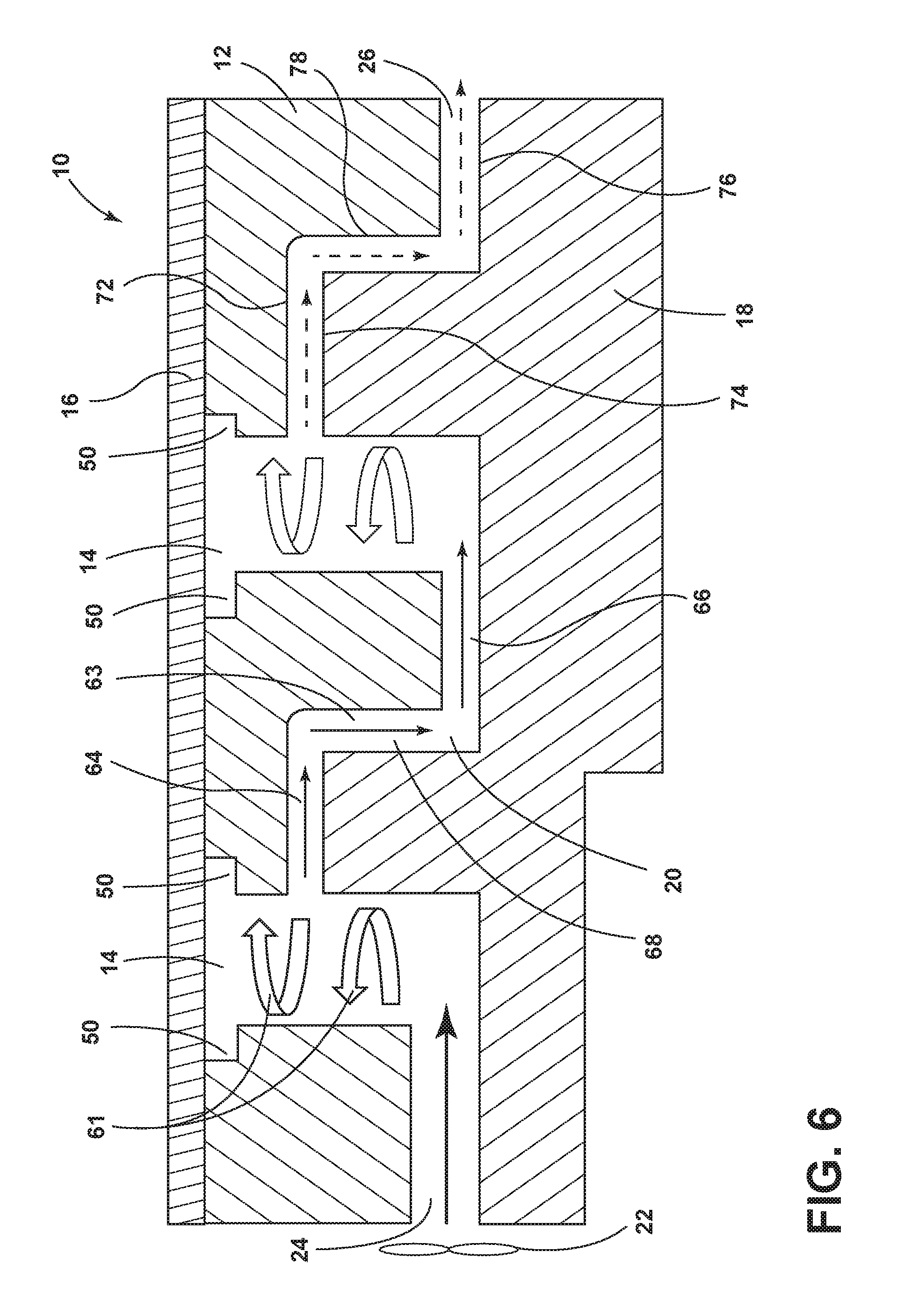
FIG. 6 is a front elevational cross-sectional view of a seat cushion assembly of the present disclosure;
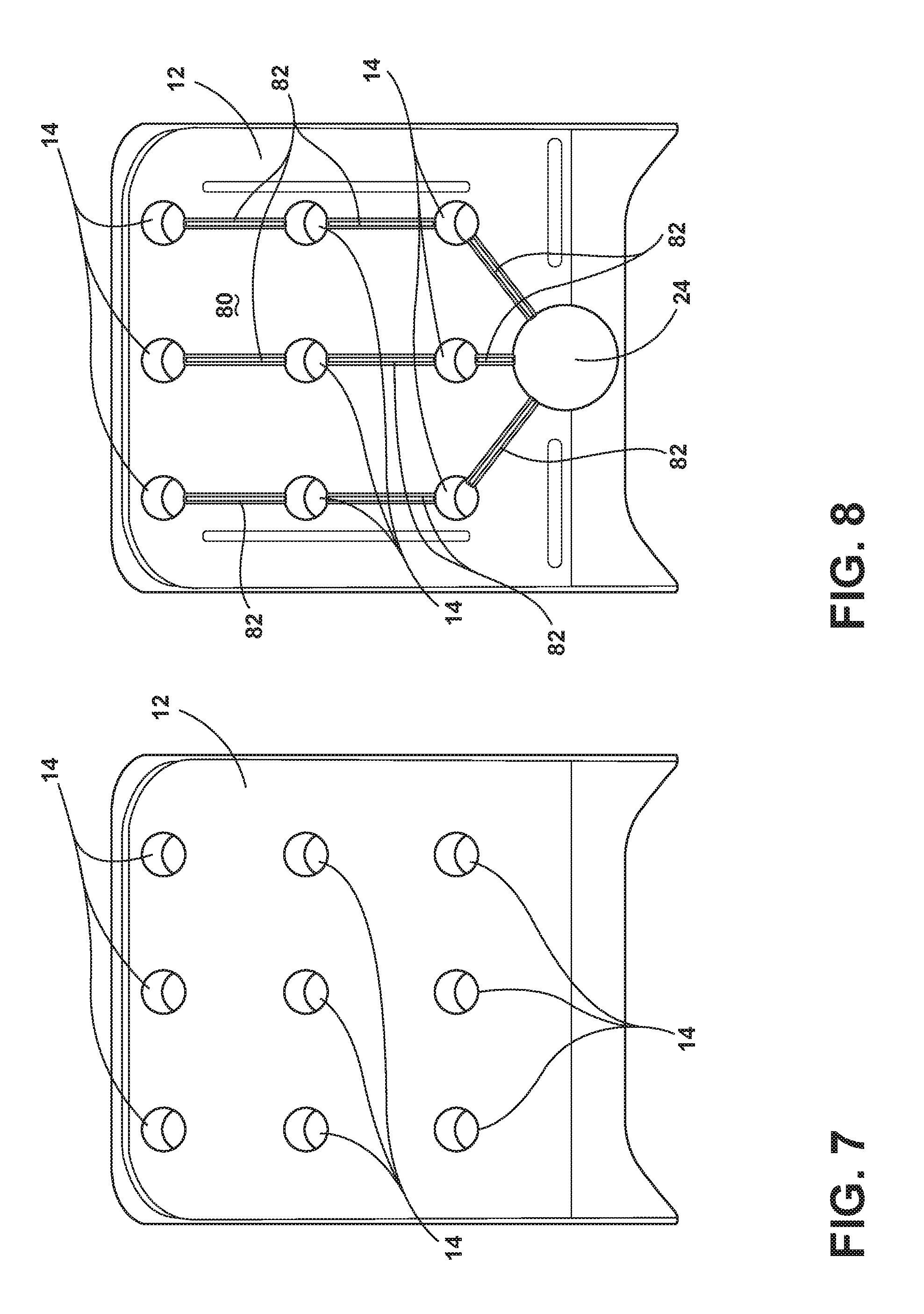
FIG. 7 is a front elevational view of an upper foam pad of the seat cushion assembly of FIG. 6 with a plurality of air cooling columns;
FIG. 8 is a rear elevational view of the upper foam pad of the seat cushion assembly of FIG. 7;
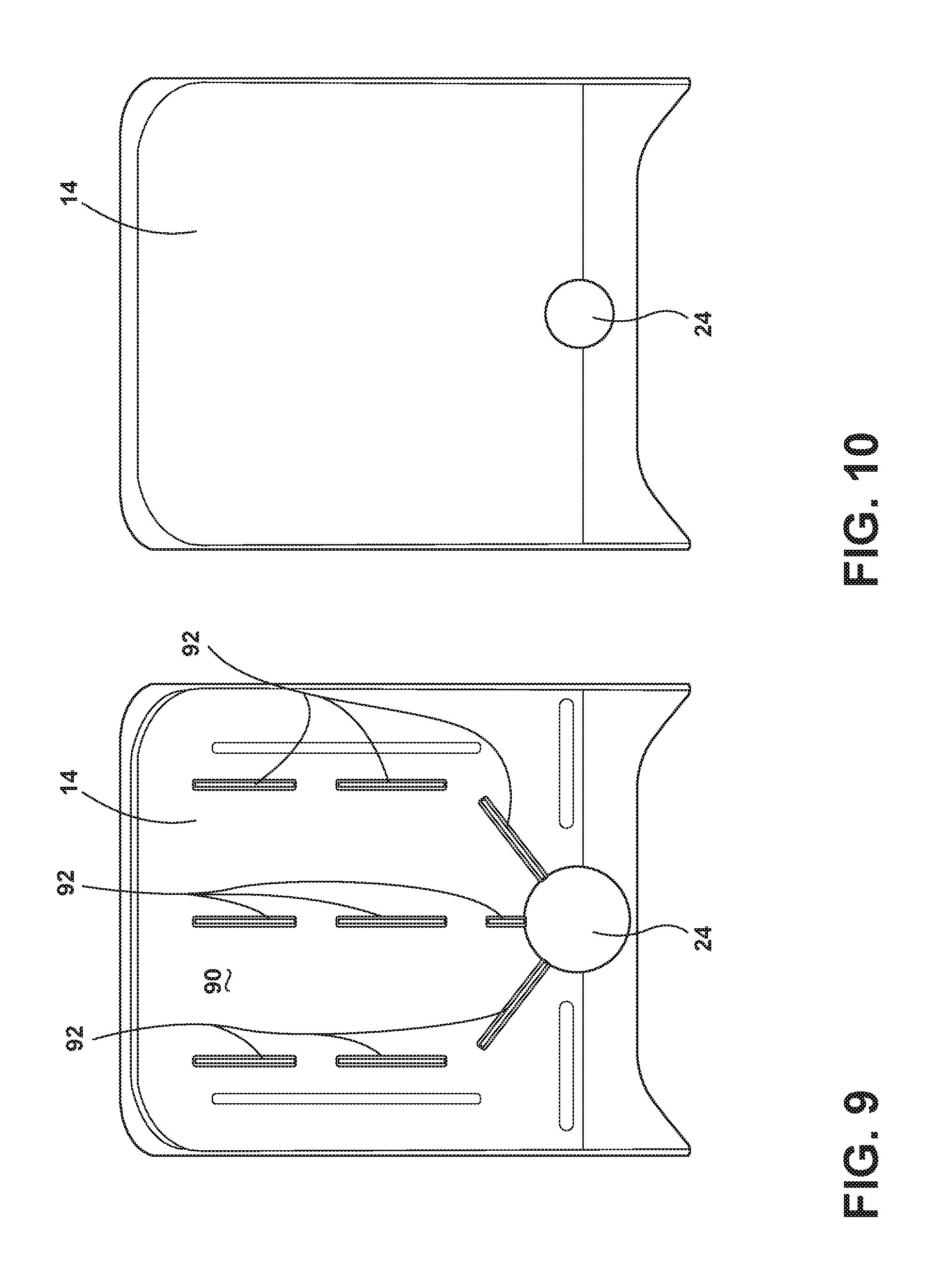
FIG. 9 is a front elevational view of a second foam pad of a seat cushion assembly of the present disclosure; and
FIG. 10 is a rear elevational view of the second foam pad of the seat cushion assembly of FIG. 9.
DETAILED DESCRIPTION OF THE EMBODIMENTS
For purposes of description herein, the terms "upper," "lower," "right," "left," "rear," "front," "vertical," "horizontal," and derivatives thereof shall relate to the disclosure as oriented in FIG. 1. However, it is to be understood that the disclosure may assume various alternative orientations, except where expressly specified to the contrary. It is also to be understood that the specific devices and processes illustrated in the attached drawings, and described in the following specification are simply exemplary embodiments of the inventive concepts defined in the appended claims. Hence, specific dimensions and other physical characteristics relating to the embodiments disclosed herein are not to be considered as limiting, unless the claims expressly state otherwise.
In this document, relational terms, such as first and second, top and bottom, and the like, are used solely to distinguish one entity or action from another entity or action, without necessarily requiring or implying any actual such relationship or order between such entities or actions. The terms "comprises," "comprising," or any other variation thereof, are intended to cover a non-exclusive inclusion, such that a process, method, article, or apparatus that comprises a list of elements does not include only those elements but may include other elements not expressly listed or inherent to such process, method, article, or apparatus. An element proceeded by "comprises . . . a" does not, without more constraints, preclude the existence of additional identical elements in the process, method, article, or apparatus that comprises the element.
Traditional expanded polypropylene (EPP) pads used for cushion assemblies are difficult to cool within seating assemblies. Adding cooling holes for ventilation in an EPP pad can result in failures of these cushion assemblies. These failures typically result from point loading or abuse loading that results high tensile stresses that occur at the bottom of an EPP pad or the cushion assembly. As a result, an improved construction that can better manage point loading or abuse loading would prove beneficial.
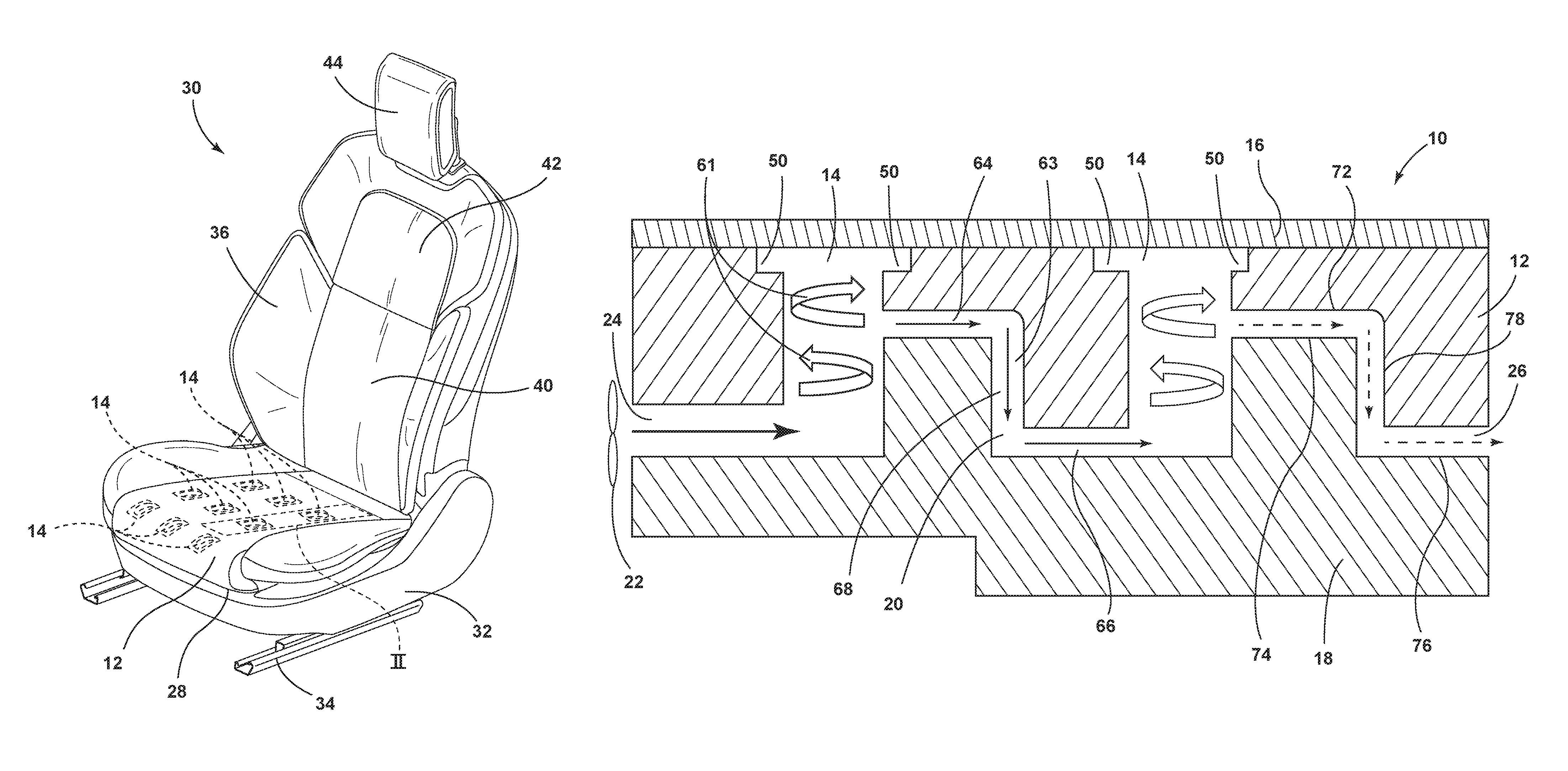
Referring to the embodiment generally illustrated in FIGS. 1-10, reference numeral 10 generally designates a seat cushion assembly that includes a first foam pad 12 defining at least one air cooling column 14 disposed therethrough. A topper pad 16 is disposed over the first foam pad 12 and the at least one air cooling column 14. A second foam pad 18 is disposed below the first foam pad 12. The second foam pad 18 and the first foam pad 12 define a flow channel 20 in fluid communication with the at least one air cooling column 14. An air mover 22 moves air from an air intake 24 of the flow channel 20 to an air exhaust 26 of the flow channel 20.
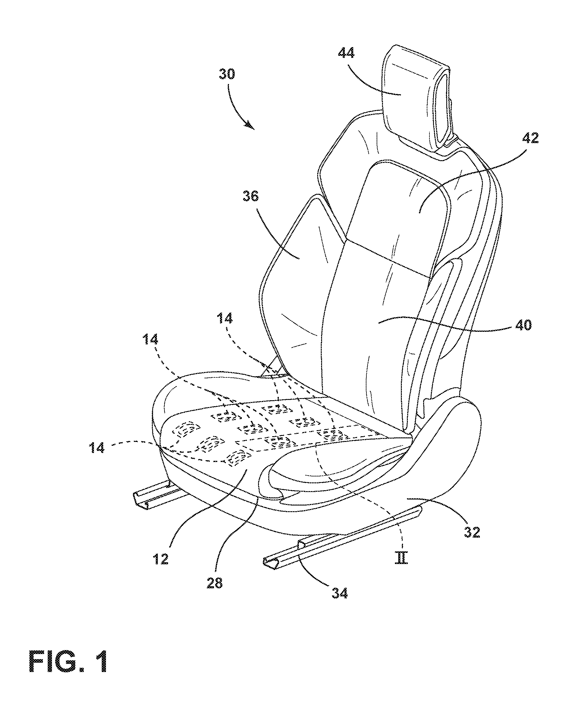
With reference now to FIGS. 1 and 2, the seat cushion assembly 10 is disposed in a seat 28 of a seating assembly 30 and may be used in any vehicle, such as a car, a truck, a van, etc. It is also contemplated that the concept set forth in this disclosure may be utilized in a front or forward position of the vehicle as well as a rear or rearward position of the vehicle. The seat cushion assembly 10, as illustrated, includes a seat base 32 that is positioned on rail slides 34 to allow fore and aft movement of the seat cushion assembly 10 relative to the vehicle. The seat 28 is operably coupled with the seat base 32 and is movable relative thereto, as set forth in further detail below. In addition, a seatback 36 of the seating assembly 30 includes a lower lumbar region 40 and an upper thoracic region 42 as well as a head restraint 44. Each of the components of the seatback 36 may be configured for adjustability to properly support the weight of different sized occupants inside the vehicle.
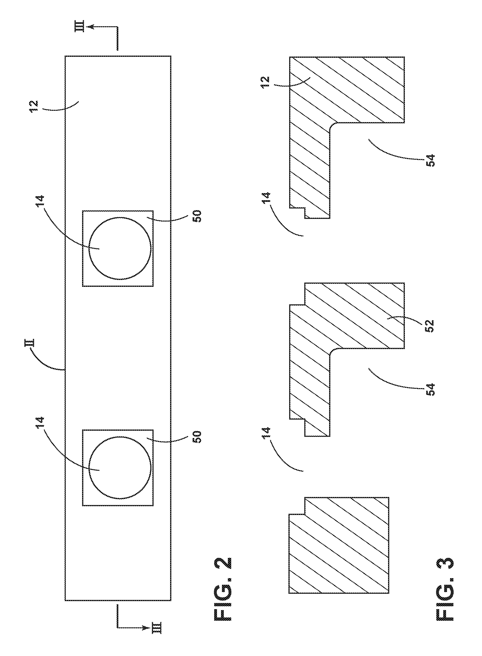
With reference now to FIGS. 2 and 3, one aspect of the seat cushion assembly 10 is illustrated taken at area II of FIG. 1. Specifically, the first or upper foam pad 12 is illustrated. The upper foam pad 12 is configured to provide support to the buttocks of an occupant, and is also configured to provide cooling to the buttocks of the occupant. Two air cooling columns 14 are illustrated in area II. However, it will be understood that any number of air cooling columns may be present through the upper foam pad 12. As shown in FIG. 3, the air cooling columns 14 are open at a top portion thereof and include a recessed periphery 50 that aids in cooling an occupant. A bottom portion 52 of the first foam pad 12 includes enlarged recesses 54 that, together with the second foam pad 18, define the flow channels 20. It will be understood that the first foam pad 12 may take on a variety of shapes and constructions, and that the illustrated construction is exemplary.
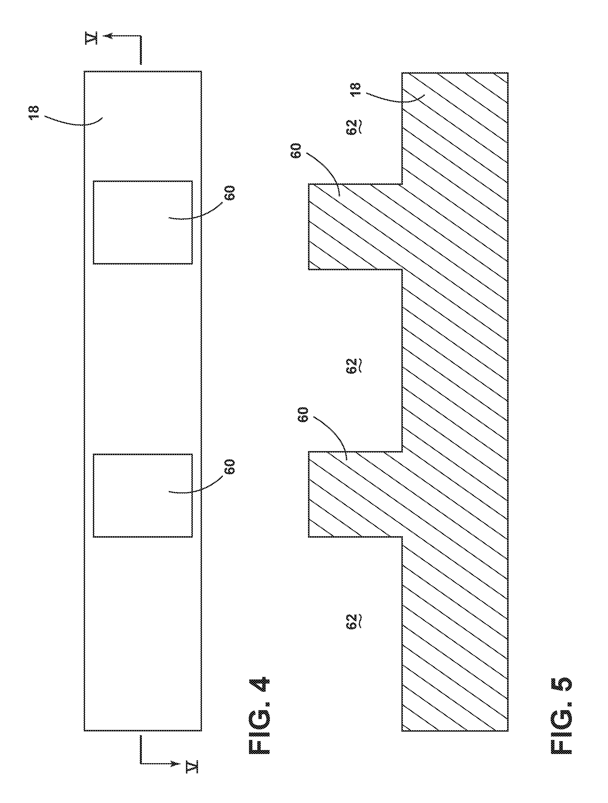
With reference now to FIGS. 4 and 5, the second or lower foam pad 18 is illustrated. The second foam pad 18 includes upwardly extending columns 60 configured to protrude into the recesses 54 of the first foam pad 12. The second foam pad 18 includes a top portion thereof that defines cavities 62. The cavities 62 and the columns 60 of the first and second foam pads 12, 18 together define the flow channel 20. As with the first foam pad 12, the second foam pad 18 may take on a variety of shapes and constructions and is not limited to the construction as set forth in FIGS. 4 and 5.
With reference now to FIG. 6, the seat cushion assembly 10 that is made up by the topper pad 16, the first foam pad 12, and the second foam pad 18 is illustrated. The topper pad 16 is generally porous in construction so that fluid or air can pass through the topper pad 16. It will be understood that air may be drawn into or blown out of the topper pad 16. The air mover 22 pushes air through the air intake 24 of the flow channel 20. The air mover 22 may be a blower that forces air from the air intake 24 of the flow channel 20 to the air exhaust 26 of the flow channel 20. In the illustrated embodiment, the air intake 24 is oriented in a horizontal direction relative to the seat cushion assembly 10. However, it will be understood that the air intake 24 may also be oriented in a vertical direction relative to the seat cushion assembly 10. The air mover 22 pushes air into the air intake 24 of the flow channel 20 until the air reaches the first vertical air cooling column 14. The air may then move in a turbulent fashion, generally in the direction of arrows 61, cooling the topper pad 16, and consequently, cooling the occupant. Air is also forced into a first internal transfer portion 63 of the flow channel 20. The first internal transfer portion 63 includes a first lateral portion 64 that connects with a second lateral portion 66 by way of a vertical portion 68. The flow of fluid, which may be air, is generally laminar as the fluid passes through the first internal transfer portion 63. However, the flow of fluid is generally turbulent within the first and second air cooling columns 14. It will be understood that this construction is exemplary and that other constructions may also be utilized. Air, which is still somewhat cool, but which has received some heat gain from the first air cooling column 14, is then driven into the second air cooling column 14, to cool the topper pad 16, and consequently, the occupant, at a location proximate the second air cooling column 14. Air is also forced along the back portion of the air cooling column 14 and into a second internal transfer portion 72 that includes a first lateral portion 74 that connects with a second lateral portion 76 by way of a vertical portion 78. The warmed air ultimately exits the seat cushion assembly 10 through the air exhaust 26.
With reference now to FIGS. 7 and 8, one example of the upper foam pad 12 is illustrated. The upper foam pad 12, as shown in FIG. 8, illustrates a plurality of air cooling columns 14. In addition, a bottom side 80 of the upper foam pad 12 includes the plurality of air cooling columns 14, which are in fluid connection via grooves 82 that form a portion of the flow channels 20. Each of the grooves 82 is in communication with an air mover hole, which defines the air intake 24. It will be understood that the air mover 22 may draw air from the topper pad 16 of the seat cushion assembly 10, or may push air toward the topper pad 16 of the seat cushion assembly 10.
With reference now to FIGS. 9 and 10, the second foam pad 18 is illustrated. The second foam pad 18 is similar in construction to the first foam pad 12, but lacks air cooling columns 14 that are in communication with the topper pad 16. However, a top side 90 of the second foam pad 18 does include a plurality of grooves 92 that, together with the grooves 82 of the top foam pad 12, define the flow channels 20. As with the grooves 82 of the first foam pad 12, the grooves 92 of the bottom foam pad 18 are ultimately in communication with the air mover hole at a rear portion of the seat cushion assembly 10. Attachment features are disposed below the second foam pad 18 and are configured to secure the second foam pad 18 to an underlying seating suspension assembly.
It will be understood by one having ordinary skill in the art that construction of the described disclosure and other components is not limited to any specific material. Other exemplary embodiments of the disclosure disclosed herein may be formed from a wide variety of materials, unless described otherwise herein.
For purposes of this disclosure, the term "coupled" (in all of its forms, couple, coupling, coupled, etc.) generally means the joining of two components (electrical or mechanical) directly or indirectly to one another. Such joining may be stationary in nature or moveable in nature. Such joining may be achieved with the two components (electrical or mechanical) and any additional intermediate members being integrally formed as a single unitary body with one another or with the two components. Such joining may be permanent in nature or may be removable or releasable in nature unless otherwise stated.
It is also important to note that the construction and arrangement of the elements of the disclosure as shown in the exemplary embodiments is illustrative only. Although only a few embodiments of the present innovations have been described in detail in this disclosure, those skilled in the art who review this disclosure will readily appreciate that many modifications are possible (e.g., variations in sizes, dimensions, structures, shapes and proportions of the various elements, values of parameters, mounting arrangements, use of materials, colors, orientations, etc.) without materially departing from the novel teachings and advantages of the subject matter recited. For example, elements shown as integrally formed may be constructed of multiple parts or elements shown as multiple parts may be integrally formed, the operation of the interfaces may be reversed or otherwise varied, the length or width of the structures and/or members or connector or other elements of the system may be varied, the nature or number of adjustment positions provided between the elements may be varied. It should be noted that the elements and/or assemblies of the system may be constructed from any of a wide variety of materials that provide sufficient strength or durability, in any of a wide variety of colors, textures, and combinations. Accordingly, all such modifications are intended to be included within the scope of the present innovations. Other substitutions, modifications, changes, and omissions may be made in the design, operating conditions, and arrangement of the desired and other exemplary embodiments without departing from the spirit of the present innovations.
It will be understood that any described processes or steps within described processes may be combined with other disclosed processes or steps to form structures within the scope of the present disclosure. The exemplary structures and processes disclosed herein are for illustrative purposes and are not to be construed as limiting.
It is also to be understood that variations and modifications can be made on the aforementioned structures and methods without departing from the concepts of the present disclosure, and further it is to be understood that such concepts are intended to be covered by the following claims unless these claims by their language expressly state otherwise.
* * * * *
References
D00000
D00001
D00002
D00003
D00004
D00005
D00006
XML
uspto.report is an independent third-party trademark research tool that is not affiliated, endorsed, or sponsored by the United States Patent and Trademark Office (USPTO) or any other governmental organization. The information provided by uspto.report is based on publicly available data at the time of writing and is intended for informational purposes only.
While we strive to provide accurate and up-to-date information, we do not guarantee the accuracy, completeness, reliability, or suitability of the information displayed on this site. The use of this site is at your own risk. Any reliance you place on such information is therefore strictly at your own risk.
All official trademark data, including owner information, should be verified by visiting the official USPTO website at www.uspto.gov. This site is not intended to replace professional legal advice and should not be used as a substitute for consulting with a legal professional who is knowledgeable about trademark law.