Golf club heads and methods to manufacture golf club heads
Parsons , et al. Nov
U.S. patent number 10,478,684 [Application Number 16/039,496] was granted by the patent office on 2019-11-19 for golf club heads and methods to manufacture golf club heads. This patent grant is currently assigned to Parsons Xtreme Golf, LLC. The grantee listed for this patent is Parsons Xtreme Golf, LLC. Invention is credited to Michael R. Nicolette, Robert R. Parsons, Bradley D. Schweigert.


View All Diagrams
| United States Patent | 10,478,684 |
| Parsons , et al. | November 19, 2019 |
Golf club heads and methods to manufacture golf club heads
Abstract
Embodiments of golf club heads and methods to manufacture golf club heads are generally described herein. In one example, a golf club head may include a body portion having a toe portion, a heel portion, a top portion, a sole portion, a front portion, a back portion, a hosel portion, a first interior cavity, and a hosel transition portion between the first interior cavity and the hosel portion. The golf club head may include a second interior cavity extending into the hosel transition portion and connected to the first interior cavity. The body portion may include a port connected to the first interior cavity. The first interior cavity may be filled with a polymer material from the port. The golf club head may include a mass portion located at or below a horizontal midplane of the body portion. Other examples and embodiments may be described and claimed.
| Inventors: | Parsons; Robert R. (Scottsdale, AZ), Nicolette; Michael R. (Scottsdale, AZ), Schweigert; Bradley D. (Anthem, AZ) | ||||||||||
|---|---|---|---|---|---|---|---|---|---|---|---|
| Applicant: |
|
||||||||||
| Assignee: | Parsons Xtreme Golf, LLC
(Scottsdale, AZ) |
||||||||||
| Family ID: | 64013528 | ||||||||||
| Appl. No.: | 16/039,496 | ||||||||||
| Filed: | July 19, 2018 |
Prior Publication Data
| Document Identifier | Publication Date | |
|---|---|---|
| US 20180318673 A1 | Nov 8, 2018 | |
Related U.S. Patent Documents
| Application Number | Filing Date | Patent Number | Issue Date | ||
|---|---|---|---|---|---|
| 15841022 | Dec 13, 2017 | ||||
| 15701131 | Sep 11, 2017 | ||||
| 15685986 | Aug 24, 2017 | ||||
| 15628251 | Jun 20, 2017 | ||||
| 15209364 | Jul 13, 2016 | ||||
| PCT/US2015/016666 | Feb 19, 2015 | ||||
| 16039496 | Jul 19, 2018 | ||||
| 15209364 | Jul 13, 2016 | ||||
| 14618501 | Feb 10, 2015 | 9427634 | |||
| 14589277 | Jan 5, 2015 | 9421437 | |||
| 14513073 | Oct 13, 2014 | 8961336 | |||
| 14498603 | Sep 26, 2014 | 9199143 | |||
| 16039496 | Jul 19, 2018 | ||||
| 15478542 | Apr 4, 2017 | ||||
| 14709195 | May 11, 2015 | 9649542 | |||
| 16039496 | Jul 19, 2018 | ||||
| 15683564 | Aug 22, 2017 | ||||
| 15598949 | May 18, 2017 | ||||
| 14711596 | May 13, 2015 | 9675853 | |||
| 16039496 | Jul 19, 2018 | ||||
| 15947383 | Apr 6, 2018 | ||||
| 15842632 | Dec 14, 2017 | 10029159 | |||
| 15263018 | Sep 12, 2016 | 9878220 | |||
| 15043090 | Feb 12, 2016 | 9468821 | |||
| 16039496 | Jul 19, 2018 | ||||
| 15842583 | Dec 14, 2017 | ||||
| 15631610 | Jun 23, 2017 | ||||
| 15360707 | Nov 23, 2016 | 10029158 | |||
| 15043106 | Feb 12, 2016 | 9533201 | |||
| 16039496 | Jul 19, 2018 | ||||
| 15703639 | Sep 13, 2017 | ||||
| 15484794 | Apr 11, 2017 | 9814952 | |||
| 16039496 | Jul 19, 2018 | ||||
| 15842591 | Dec 14, 2017 | ||||
| PCT/US2016/042075 | Jul 13, 2016 | ||||
| 15188718 | Jun 21, 2016 | 9610481 | |||
| 16039496 | Jul 19, 2018 | ||||
| 15462281 | Mar 17, 2017 | ||||
| 16039496 | Jul 19, 2018 | ||||
| 29616949 | Sep 11, 2017 | ||||
| 15802819 | Nov 3, 2017 | ||||
| 15793648 | Oct 25, 2017 | ||||
| 15791020 | Oct 23, 2017 | ||||
| 15785001 | Oct 16, 2017 | ||||
| 16039496 | Jul 19, 2018 | ||||
| 29622326 | Oct 16, 2017 | ||||
| 61942515 | Feb 20, 2014 | ||||
| 61945560 | Feb 27, 2014 | ||||
| 61948839 | Mar 6, 2014 | ||||
| 61952470 | Mar 13, 2014 | ||||
| 61992555 | May 13, 2014 | ||||
| 62010836 | Jun 11, 2014 | ||||
| 62011859 | Jun 13, 2014 | ||||
| 62032770 | Aug 4, 2014 | ||||
| 62041538 | Aug 25, 2014 | ||||
| 62021415 | Jul 7, 2014 | ||||
| 62058858 | Oct 2, 2014 | ||||
| 62137494 | Mar 24, 2015 | ||||
| 62118403 | Feb 19, 2015 | ||||
| 62159856 | May 11, 2015 | ||||
| 62209780 | Aug 25, 2015 | ||||
| 62277636 | Jan 12, 2016 | ||||
| 62275443 | Jan 6, 2016 | ||||
| 62276358 | Jan 8, 2016 | ||||
| 62321652 | Apr 12, 2016 | ||||
| 62343739 | May 31, 2016 | ||||
| 62433661 | Dec 13, 2016 | ||||
| 62502442 | May 5, 2017 | ||||
| 62508794 | May 19, 2017 | ||||
| 62512033 | May 28, 2017 | ||||
| 62570493 | Oct 10, 2017 | ||||
| 62536345 | Jul 24, 2017 | ||||
| 62642531 | Mar 13, 2018 | ||||
| Current U.S. Class: | 1/1 |
| Current CPC Class: | A63B 53/0466 (20130101); A63B 60/54 (20151001); A63B 53/0487 (20130101); A63B 53/047 (20130101); A63B 60/02 (20151001); A63B 53/0475 (20130101); A63B 53/0408 (20200801); A63B 53/0445 (20200801); A63B 60/002 (20200801); A63B 2209/00 (20130101); A63B 2053/0491 (20130101); A63B 2053/0479 (20130101) |
| Current International Class: | A63B 53/04 (20150101); A63B 60/00 (20150101); A63B 60/54 (20150101); A63B 60/02 (20150101) |
| Field of Search: | ;473/324-350,287-292 |
References Cited [Referenced By]
U.S. Patent Documents
| 1133129 | March 1915 | Govan |
| 1529009 | March 1925 | Carpenter |
| 3020048 | February 1962 | Carroll |
| D215101 | September 1969 | Sabat |
| D239550 | April 1976 | Timbrook |
| D294617 | March 1988 | Perkins |
| 4754977 | July 1988 | Sahm |
| 4824116 | April 1989 | Nagamoto et al. |
| 4988104 | January 1991 | Shiotani et al. |
| 5158296 | October 1992 | Lee |
| 5176384 | January 1993 | Sata et al. |
| 5184823 | February 1993 | Desboilles |
| 5213328 | May 1993 | Long et al. |
| D336672 | June 1993 | Gorman |
| 5351958 | October 1994 | Helmstetter |
| 5419560 | May 1995 | Bamber |
| 5425535 | June 1995 | Gee |
| D361358 | August 1995 | Simmons |
| 5447311 | September 1995 | Viollaz et al. |
| 5451056 | September 1995 | Manning |
| 5540437 | July 1996 | Bamber |
| 5637045 | June 1997 | Igarashi |
| 5647808 | July 1997 | Hosokawa |
| 5669830 | September 1997 | Bamber |
| 5738596 | April 1998 | Meyer |
| 5766091 | June 1998 | Humphrey et al. |
| 5766092 | June 1998 | Mimeur |
| 5769735 | June 1998 | Hosokawa |
| 5772527 | June 1998 | Liu |
| 5797807 | August 1998 | Moore |
| 5827132 | October 1998 | Bamber |
| D408485 | April 1999 | Takahashi et al. |
| 5899821 | May 1999 | Hsu et al. |
| 5935016 | August 1999 | Antonious |
| D421080 | February 2000 | Chen |
| 6042486 | March 2000 | Gallagher |
| D426276 | June 2000 | Besnard et al. |
| 6077171 | June 2000 | Yoneyama |
| 6162133 | December 2000 | Peterson |
| 6165081 | December 2000 | Chou |
| D442659 | May 2001 | Kubica et al. |
| 6231458 | May 2001 | Cameron et al. |
| 6238302 | May 2001 | Helmstetter et al. |
| D445862 | July 2001 | Ford |
| 6254494 | July 2001 | Hasebe et al. |
| 6290609 | September 2001 | Takeda |
| D469833 | February 2003 | Roberts et al. |
| D475107 | May 2003 | Madore |
| 6638182 | October 2003 | Kosmatka |
| 6695714 | February 2004 | Bliss et al. |
| 6702693 | March 2004 | Bamber |
| 6780123 | August 2004 | Hasebe |
| 6811496 | November 2004 | Wahl et al. |
| 6830519 | December 2004 | Reed et al. |
| D502975 | March 2005 | Schweigert et al. |
| D503204 | March 2005 | Nicolette et al. |
| D508545 | August 2005 | Roberts et al. |
| 6923733 | August 2005 | Chen |
| D514183 | January 2006 | Schweigert et al. |
| D523501 | June 2006 | Nicolette et al. |
| 7115048 | October 2006 | Kusumoto |
| 7121956 | October 2006 | Lo |
| 7128663 | October 2006 | Bamber |
| 7153222 | December 2006 | Gilbert et al. |
| D534595 | January 2007 | Hasebe |
| 7156751 | January 2007 | Wahl et al. |
| 7182698 | February 2007 | Tseng |
| 7207900 | April 2007 | Nicolette et al. |
| D543601 | May 2007 | Kawami |
| 7281991 | October 2007 | Gilbert |
| D555219 | November 2007 | Lin |
| 7303485 | December 2007 | Tseng |
| 7303486 | December 2007 | Imamoto |
| 7326127 | February 2008 | Hou et al. |
| 7351164 | April 2008 | Schweigert et al. |
| 7396299 | July 2008 | Nicolette et al. |
| 7455600 | November 2008 | Imamoto et al. |
| 7588502 | September 2009 | Nishino |
| 7611424 | November 2009 | Nagai et al. |
| 7658686 | February 2010 | Soracco |
| 7662051 | February 2010 | Chen |
| D618293 | June 2010 | Foster et al. |
| 7744484 | June 2010 | Chao |
| 7744487 | June 2010 | Tavares et al. |
| 7794333 | September 2010 | Wallans et al. |
| 7798917 | September 2010 | Nguyen et al. |
| 7803068 | September 2010 | Clausen et al. |
| 7815521 | October 2010 | Ban et al. |
| 7846040 | December 2010 | Ban |
| 7938738 | May 2011 | Roach |
| 8062150 | November 2011 | Gilbert et al. |
| 8088025 | January 2012 | Wahl et al. |
| 8092319 | January 2012 | Cackett et al. |
| 8105180 | January 2012 | Cackett et al. |
| 8221262 | July 2012 | Cackett et al. |
| 8241141 | August 2012 | Takechi |
| 8246487 | August 2012 | Cackett et al. |
| 8328662 | December 2012 | Nakamura et al. |
| 8376878 | February 2013 | Bennett et al. |
| 8393976 | March 2013 | Soracco et al. |
| D681142 | April 2013 | Fossum et al. |
| 8414422 | April 2013 | Peralta et al. |
| 8449406 | May 2013 | Frame et al. |
| 8506420 | August 2013 | Hocknell et al. |
| 8545343 | October 2013 | Boyd et al. |
| 8574094 | November 2013 | Nicolette et al. |
| 8657700 | February 2014 | Nicolette et al. |
| 8663026 | March 2014 | Blowers et al. |
| 8690710 | April 2014 | Nicolette et al. |
| 8753230 | June 2014 | Stokke et al. |
| 8827832 | September 2014 | Breier et al. |
| 8827833 | September 2014 | Amano et al. |
| 8845455 | September 2014 | Ban et al. |
| 8900072 | December 2014 | Willett et al. |
| D722352 | February 2015 | Nicolette et al. |
| D723120 | February 2015 | Nicolette et al. |
| 8961336 | February 2015 | Parsons et al. |
| D726265 | April 2015 | Nicolette |
| 9044653 | June 2015 | Wahl et al. |
| 9199143 | December 2015 | Parsons et al. |
| D748214 | January 2016 | Nicolette et al. |
| D748749 | February 2016 | Nicolette et al. |
| D756471 | May 2016 | Nicolette et al. |
| 9345938 | May 2016 | Parsons et al. |
| 9346203 | May 2016 | Parsons et al. |
| 9364727 | June 2016 | Parsons et al. |
| 9421437 | August 2016 | Parsons et al. |
| 9427634 | August 2016 | Parsons et al. |
| 9468821 | October 2016 | Parsons et al. |
| 9517393 | December 2016 | Cardani et al. |
| 9533201 | January 2017 | Parsons et al. |
| 9610481 | September 2017 | Parsons et al. |
| 9844710 | December 2017 | Parsons et al. |
| 9878220 | January 2018 | Parsons et al. |
| 10029159 | July 2018 | Parsons et al. |
| 10086238 | October 2018 | Roach |
| 2002/0107087 | August 2002 | Fagot |
| 2003/0032499 | February 2003 | Wahl |
| 2003/0092499 | May 2003 | Gilbert |
| 2003/0139222 | July 2003 | Vadersen |
| 2003/0139226 | July 2003 | Cheng et al. |
| 2003/0176231 | September 2003 | Hasebe |
| 2004/0082401 | April 2004 | Takeda |
| 2004/0204263 | October 2004 | Fagot et al. |
| 2004/0266550 | December 2004 | Gilbert et al. |
| 2005/0009632 | January 2005 | Schweigert et al. |
| 2005/0014573 | January 2005 | Lee |
| 2005/0043117 | February 2005 | Gilbert et al. |
| 2005/0119066 | June 2005 | Stites et al. |
| 2005/0143188 | June 2005 | Tseng |
| 2005/0164802 | July 2005 | Wood |
| 2005/0239569 | October 2005 | Best et al. |
| 2005/0277485 | December 2005 | Hou et al. |
| 2006/0111200 | May 2006 | Poynor |
| 2007/0032308 | February 2007 | Fagot et al. |
| 2007/0225084 | September 2007 | Schweigert et al. |
| 2007/0249431 | October 2007 | Lin |
| 2008/0022502 | January 2008 | Tseng |
| 2008/0058113 | March 2008 | Nicolette et al. |
| 2008/0188322 | August 2008 | Anderson et al. |
| 2008/0300065 | December 2008 | Schweigert |
| 2008/0318705 | December 2008 | Clausen et al. |
| 2008/0318706 | December 2008 | Larson |
| 2008/0318708 | December 2008 | Clausen |
| 2009/0029790 | January 2009 | Nicolette et al. |
| 2009/0042665 | February 2009 | Morales et al. |
| 2009/0163295 | June 2009 | Tseng |
| 2010/0130306 | May 2010 | Schweigert |
| 2010/0178999 | July 2010 | Nicolette et al. |
| 2010/0298065 | November 2010 | Soracco |
| 2010/0323812 | December 2010 | Boyd et al. |
| 2011/0111883 | May 2011 | Cackett |
| 2011/0165963 | July 2011 | Cackett et al. |
| 2011/0269567 | November 2011 | Ban et al. |
| 2011/0294596 | December 2011 | Ban |
| 2012/0322575 | December 2012 | Tavares |
| 2013/0137532 | May 2013 | Deshmukh et al. |
| 2013/0225319 | August 2013 | Kato |
| 2013/0281226 | October 2013 | Ban |
| 2013/0288823 | October 2013 | Hebreo |
| 2013/0303303 | November 2013 | Ban |
| 2013/0310192 | November 2013 | Wahl et al. |
| 2013/0316842 | November 2013 | Demkowski |
| 2014/0080621 | March 2014 | Nicolette et al. |
| 2014/0128175 | May 2014 | Jertson et al. |
| 2014/0274441 | May 2014 | Greer |
| 2014/0274442 | September 2014 | Honea et al. |
| 2014/0274451 | September 2014 | Knight et al. |
| 2015/0231454 | August 2015 | Parsons et al. |
| 2015/0231806 | August 2015 | Parsons et al. |
| 2016/0144247 | May 2016 | Chen |
| 297 15 997 | Mar 1998 | DE | |||
| 2 249 031 | Apr 1992 | GB | |||
| H10-127832 | May 1998 | JP | |||
| H10-277187 | Oct 1998 | JP | |||
| 2001-346924 | Dec 2001 | JP | |||
| 2002143356 | May 2002 | JP | |||
| 2004-313777 | Nov 2004 | JP | |||
| 92/15374 | Sep 1992 | WO | |||
Other References
|
International Search Report and Written Opinion received in connection with corresponding application No. PCT/US2015/016666, dated May 14, 2015 (8 pages). cited by applicant . U.S. Appl. No. 29/512,313, Nicolette, "Golf Club Head," filed Dec. 18, 2014. cited by applicant . Kozuchowski, Zak, "Callaway Mack Daddy 2 PM Grind Wedges" (http://www.golfwrz.com/276203/callaway-mack-daddy-2-pm-grind-wedges/), www.golfwrx.com, GolfWRX Holdings, LLC, published Jan. 21, 2015. cited by applicant . Wall, Jonathan, "Details: Phil's Prototype Mack Daddy PM-Grind Wedge," (http://www.pgatour.com/equipmentreport/2015/01/21/callaway-wedge.html), www.pgatour.com, PGA Tour, Inc., published Jan. 21, 2015. cited by applicant . Taylor Made Golf Company, Inc., https://taylormadegolf.com/on/demandware.static/-/Sites-TMaG-Library/defa- ult/v1459859109590/docs/productspecs/TM_S2013_Catalog18.pdf., published Jan. 2013. cited by applicant . RocketBladez Press Release, "GolfBalled", http://golfballed.com/index.php?option=com_content&view=article&id=724:ta- ylormade- . . . Oct. 13, 2017, published Jan. 3, 2013. cited by applicant . International Preliminary Report on Patentability received in connection with corresponding application No. PCT/US2016/017854, dated Jul. 11, 2017 (9 pages). cited by applicant . International Search Report and Written Opinion Issued in Connection with Corresponding International Application No. PCT/US2018/043323, dated Oct. 23, 2018, 9 pages. cited by applicant. |
Primary Examiner: Passaniti; Sebastiano
Parent Case Text
CROSS REFERENCE
This application is a continuation-in-part of application Ser. No. 15/841,022, filed Dec. 13, 2017, which is a continuation of application Ser. No. 15/701,131, filed Sep. 11, 2017, which is a continuation-in-part of application Ser. No. 15/685,986, filed Aug. 24, 2017, which is a continuation of application Ser. No. 15/628,251, filed Jun. 20, 2017, which is a continuation of application Ser. No. 15/209,364, filed on Jul. 13, 2016, is a continuation of International Application No. PCT/US15/16666, filed Feb. 19, 2015, which claims the benefit of U.S. Provisional Application No. 61/942,515, filed Feb. 20, 2014, U.S. Provisional Application No. 61/945,560, filed Feb. 27, 2014, U.S. Provisional Application No. 61/948,839, filed Mar. 6, 2014, U.S. Provisional Application No. 61/952,470, filed Mar. 13, 2014, U.S. Provisional Application No. 61/992,555, filed May 13, 2014, U.S. Provisional Application No. 62/010,836, filed Jun. 11, 2014, U.S. Provisional Application No. 62/011,859, filed Jun. 13, 2014, and U.S. Provisional Application No. 62/032,770, filed Aug. 4, 2014.
This application is a continuation-in-part of application Ser. No. 15/209,364, filed on Jul. 13, 2016, which is a continuation of application Ser. No. 14/618,501, filed Feb. 10, 2015, now U.S. Pat. No. 9,427,634, which is a continuation of application Ser. No. 14/589,277, filed Jan. 5, 2015, now U.S. Pat. No. 9,421,437, which is a continuation of application Ser. No. 14/513,073, filed Oct. 13, 2014, now U.S. Pat. No. 8,961,336, which is a continuation of application Ser. No. 14/498,603, filed Sep. 26, 2014, now U.S. Pat. No. 9,199,143, which claims the benefits of U.S. Provisional Application No. 62/041,538, filed Aug. 25, 2014.
This application is a continuation-in-part of application Ser. No. 15/478,542, filed Apr. 4, 2017, which is a continuation of application Ser. No. 14/709,195, filed May 11, 2015, now U.S. Pat. No. 9,649,542, which claims the benefit of U.S. Provisional Application No. 62/021,415, filed Jul. 7, 2014, U.S. Provisional Application No. 62/058,858, filed Oct. 2, 2014, and U.S. Provisional Application No. 62/137,494, filed Mar. 24, 2015.
This application is a continuation-in-part of application Ser. No. 15/683,564, filed Aug. 22, 2017, which is a continuation of application Ser. No. 15/598,949, filed May 18, 2017, which is a continuation of application Ser. No. 14/711,596, filed May 13, 2015, now U.S. Pat. No. 9,675,853, which claims the benefit of U.S. Provisional Application No. 62/118,403, filed Feb. 19, 2015, and U.S. Provisional Application No. 62/159,856, filed May 11, 2015.
This application is a continuation-in-part of application Ser. No. 15/947,383, filed Apr. 6, 2018, which is a continuation of application Ser. No. 15/842,632, filed Dec. 14, 2017, which is a continuation of application Ser. No. 15/263,018, filed Sep. 12, 2016, now U.S. Pat. No. 9,878,220, which is a continuation of application Ser. No. 15/043,090, filed Feb. 12, 2016, now U.S. Pat. No. 9,468,821, which claims the benefit of U.S. Provisional Application No. 62/209,780, filed Aug. 25, 2015, and U.S. Provisional Application No. 62/277,636, filed Jan. 12, 2016.
This application is a continuation-in-part of application Ser. No. 15/842,583, filed Dec. 14, 2017, which is a continuation of application Ser. No. 15/631,610, filed Jun. 23, 2017, which is a continuation of application Ser. No. 15/360,707, filed Nov. 23, 2016, which is a continuation of application Ser. No. 15/043,106, filed Feb. 12, 2016, now U.S. Pat. No. 9,533,201, which claims the benefit of U.S. Provisional Application No. 62/275,443, filed Jan. 6, 2016, and U.S. Provisional Application No. 62/276,358, filed Jan. 8, 2016.
This application is a continuation-in-part of application Ser. No. 15/703,639, filed Sep. 13, 2017, which is a continuation-in-part of application Ser. No. 15/484,794, filed Apr. 11, 2017, now U.S. Pat. No. 9,814,952, which claims the benefit of U.S. Provisional Application No. 62/321,652, filed Apr. 12, 2016.
This application is a continuation-in-part of application Ser. No. 15/842,591, filed Dec. 14, 2017, which is a continuation of International Application No. PCT/US16/42075, filed Jul. 13, 2016, which claims the benefit of application Ser. No. 15/188,718, filed Jun. 21, 2016, now U.S. Pat. No. 9,610,481, and U.S. Provisional Application No. 62/343,739, filed May 31, 2016.
This application is a continuation-in-part of application Ser. No. 15/462,281, filed Mar. 17, 2017, which claims the benefit of U.S. Provisional Application No. 62/433,661, filed Dec. 13, 2016.
This application is a continuation-in-part of application Ser. No. 29/616,949, filed Sep. 11, 2017.
This application is a continuation-in-part of application Ser. No. 15/802,819, filed Nov. 3, 2017, which is a continuation of application Ser. No. 15/793,648, filed Oct. 25, 2017, which is a continuation-in-part of application Ser. No. 15/791,020, filed Oct. 23, 2017, which is a continuation of application Ser. No. 15/785,001, filed Oct. 16, 2017, which claims the benefit of U.S. Provisional Application No. 62/502,442, filed May 5, 2017, U.S. Provisional Application No. 62/508,794, filed May 19, 2017, U.S. Provisional Application No. 62/512,033, filed May 28, 2017, and U.S. Provisional Application No. 62/570,493, filed Oct. 10, 2017.
This application claims the benefit of U.S. Provisional Application No. 62/536,345, filed Jul. 24, 2017, and U.S. Provisional Application No. 62/642,531, filed Mar. 13, 2018.
This application is a continuation-in-part of application Ser. No. 29/622,326, filed Oct. 16, 2017.
The disclosures of the referenced applications are incorporated herein by reference.
Claims
What is claimed is:
1. A golf club head comprising: a hollow body portion having a toe portion with a toe portion edge, a heel portion with a heel portion edge and a hosel portion, a top portion with a top portion edge, a sole portion with a sole portion edge, a front portion, and a back portion with a back wall portion; a face portion coupled to the body portion enclosing the front portion to create a first interior cavity; a hosel transition portion between the first interior cavity and the hosel portion; a second interior cavity extending into the hosel transition portion and connected to the first interior cavity, the second interior cavity extending from a location at or proximate to the top edge portion of the top portion to a location at or proximate to the sole edge portion of the sole portion, and the second interior cavity extending from the face portion toward the hosel portion; a channel on the back wall portion, the channel including at least one groove extending from the toe portion edge toward the heel portion edge, the channel defining an indented portion of the back wall portion; a first set of ports including at least one port above the channel, a distance between the at least one port of the first set of ports and the toe portion edge being substantially less than a distance between the at least one port of the first set of ports and the hosel portion; and a second set of ports including at least one port below the channel, a distance between the at least one port of the second set of ports and the toe portion edge being substantially less than a distance between the at least one port of the second set of ports and the hosel portion, wherein at least one port of the first set of ports or the second set of ports is connected to the first interior cavity to provide a connected port, wherein the first interior cavity and the second interior cavity are at least partially filled with a polymer material from the connected port, wherein a width of the at least one groove decreases from the toe portion edge toward the heel portion edge, and wherein a distance between the at least one groove and a horizontal midplane of the body portion increases from the toe portion edge toward the heel portion edge.
2. A golf club head as defined in claim 1, wherein a height of the second interior cavity extending between the top portion edge and the sole portion edge is substantially greater than a depth of the second interior cavity extending between the face portion and the hosel portion.
3. A golf club head as defined in claim 1, wherein a height of the second interior cavity extending between the top portion edge and the sole portion edge is substantially greater than a width of the second interior cavity extending between the face portion and the back wall portion.
4. A golf club head as defined in claim 1, wherein the at least one groove is between the second set of ports and the horizontal midplane.
5. A golf club head as defined in claim 1, wherein the second interior cavity comprises a bottom portion facing the toe portion and including a first curved portion extending from a location at or proximate to the top portion edge toward the sole portion edge and the hosel portion, a second curved portion extending from a location at or proximate to the sole portion edge toward the top portion edge and the hosel portion, and a third portion extending between the first curved portion and the second curved portion, the third portion having a different curvature than the first curved portion and the second curved portion.
6. A golf club head as defined in claim 1 further comprising a first set of mass portions including at least one mass portion and a second set of mass portions including at least one mass portion, wherein the at least one mass portion of the second set of mass portions has a greater height than the at least one mass portion of the first set of mass portions, wherein the at least one port of the first set of ports is configured to receive the at least one mass portion of the first set of mass portions, wherein the at least one port of the second set of ports is configured to receive the at least one mass portion of the second set of mass portions, and wherein the first set of mass portions and the second set of mass portions are made from a material having a greater density than a material of the body portion.
7. A golf club head as defined in claim 1 further comprising a first set of mass portions above the channel and a second set of mass portions below the at least one groove, wherein the second set of mass portion includes a substantially greater number of mass portions than the first set of mass portions.
8. A golf club head comprising: a hollow body portion having a toe portion with a toe portion edge, a heel portion with a heel portion edge and a hosel portion, a top portion with a top portion edge, a sole portion with a sole portion edge, a front portion, and a back portion with a back wall portion; a face portion coupled to the body portion enclosing the front portion to create a first interior cavity; a hosel transition portion between the first interior cavity and the hosel portion; a second interior cavity extending into the hosel transition portion and connected to the first interior cavity, the second interior cavity having a height extending between the top portion edge and the sole portion edge and a depth extending between the face portion and the hosel portion; a channel on the back wall portion, the channel including at least one groove extending from the toe portion edge toward the heel portion edge, the channel defining an indented portion of the back wall portion; a first set of ports including at least one port above the channel, a distance between the at least one port of the first set of ports and the toe portion edge being substantially less than a distance between the at least one port of the first set of ports and the hosel portion; and a second set of ports including at least one port below the channel, a distance between the at least one port of the second set of ports and the toe portion edge being substantially less than a distance between the at least one port of the second set of ports and the hosel portion, wherein at least one of the at least one port of the first set of ports or the at least one port of the second set of ports is connected to the first interior cavity to provide a connected port, wherein the first interior cavity and the second interior cavity are at least partially filled with a polymer material from the connected port, wherein a width of the at least one groove decreases from the toe portion edge toward the heel portion edge, wherein the at least one groove is below a horizontal midplane of the body portion and above the second set of ports, and wherein the height of the second interior cavity is substantially greater than the depth of the second interior cavity.
9. A golf club head as defined in claim 8, wherein the height of the second interior cavity is substantially greater than a width of the second interior cavity extending between the face portion and the back wall portion.
10. A golf club head as defined in claim 8, wherein a distance between the at least one groove and the horizontal midplane increases from the toe portion edge toward the heel portion edge.
11. A golf club head as defined in claim 8, wherein a distance between the at least one port of the second set of ports and the at least one groove is less than a distance between the at least one port of the first set of ports and the at least one groove.
12. A golf club head as defined in claim 8, wherein a width of the channel is greater than or equal to 30% and less than or equal to 50% of a distance between the top portion edge and the sole portion edge.
13. A golf club head as defined in claim 8 further comprising a first set of mass portions including at least one mass portion and a second set of mass portions including at least one mass portion, wherein the at least one mass portion of the second set of mass portions has a greater height than the at least one mass portion of the first set of mass portions, wherein the at least one port of the first set of ports is configured to receive the at least one mass portion of the first set of mass portions, wherein the at least one port of the second set of ports is configured to receive the at least one mass portion of the second set of mass portions, and wherein the first set of mass portions and the second set of mass portions are made from a material having a greater density than a material of the body portion.
14. A golf club head as defined in claim 8 further comprising a first set of mass portions above the channel and a second set of mass portions below the at least one groove, wherein the second set of mass portion includes a substantially greater number of mass portions than the first set of mass portions.
15. A golf club head comprising: a hollow body portion comprising a material associated with a first density, the body portion having a toe portion with a toe portion edge, a heel portion with a heel portion edge and a hosel portion, a top portion with a top portion edge, a sole portion with a sole portion edge, a front portion, and a back portion with a back wall portion; a face portion coupled to the body portion enclosing the front portion to create a first interior cavity; a hosel transition portion between the first interior cavity and the hosel portion; a second interior cavity extending into the hosel transition portion and connected to the first interior cavity, the second interior cavity extending from a location at or proximate to the top edge portion of the top portion to a location at or proximate to the sole edge portion of the sole portion, and the second interior cavity extending from the face portion toward the hosel portion; a channel on the back wall portion, the channel including at least one groove extending from the toe portion edge toward the heel portion edge, the channel defining an indented portion of the back wall portion; a first port above the channel; and a second port below the channel, wherein the first port or the second port is connected to the first interior cavity to provide a connected port, wherein the first interior cavity and the second interior cavity are at least partially filled with a polymer material from the connected port, wherein the at least one groove is below a horizontal midplane of the body portion, wherein a portion of the channel is above the horizontal midplane, wherein a distance between the at least one groove and the horizontal midplane increases from the toe portion edge toward the heel portion edge, wherein a width of the channel is greater than or equal to 30% and less than or equal to 50% of a distance between the top portion edge and the sole portion edge, and wherein a distance between the second port and the groove is less than a distance between the first port and the groove.
16. A golf club head as defined in claim 15, wherein the height of the second interior cavity is substantially greater than a width of the second interior cavity extending between the face portion and the back wall portion.
17. A golf club head as defined in claim 15, wherein a distance between the second port and the at least one groove is less than a distance between the first port and the at least one groove.
18. A golf club head as defined in claim 15 further comprising a first mass portion and a second mass portion, wherein the second mass portion has a greater height than the first mass portion, wherein the first port is configured to receive the first mass portion, wherein the second port is configured to receive the second mass portion, and wherein the first mass portion and the second mass portion are made from a material having a greater density than a material of the body portion.
19. A golf club head as defined in claim 15 further comprising a first mass portion above the channel and a second mass portion below the at least one groove, wherein the second mass portion has a greater mass than the first mass portion.
20. A golf club head as defined in claim 15, wherein the second interior cavity comprises a bottom portion facing the toe portion and including a first curved portion extending from a location at or proximate to the top portion edge toward the sole portion edge and the hosel portion, a second curved portion extending from a location at or proximate to the sole portion edge toward the top portion edge and the hosel portion, and a third portion extending between the first curved portion and the second curved portion, the third portion having a different curvature than the first curved portion and the second curved portion.
Description
COPYRIGHT AUTHORIZATION
The present disclosure may be subject to copyright protection. The copyright owner has no objection to the facsimile reproduction by anyone of the present disclosure and its related documents, as they appear in the Patent and Trademark Office patent files or records, but otherwise reserves all applicable copyrights.
FIELD
The present disclosure generally relates to golf equipment, and more particularly, to golf club heads and methods to manufacturing golf club heads.
BACKGROUND
Various materials (e.g., steel-based materials, titanium-based materials, tungsten-based materials, etc.) may be used to manufacture golf club heads. By using multiple materials to manufacture golf club heads, the position of the center of gravity (CG) and/or the moment of inertia (MOI) of the golf club heads may be optimized to produce certain trajectory and spin rate of a golf ball.
BRIEF DESCRIPTION OF THE DRAWINGS
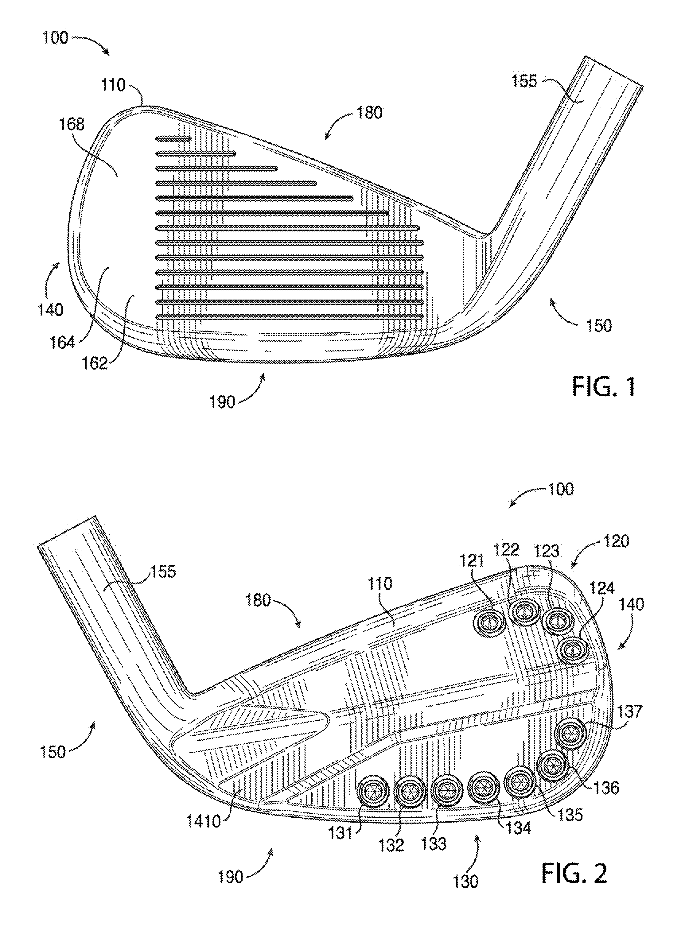
FIG. 1 depicts a front view of a golf club head according to an embodiment of the apparatus, methods, and articles of manufacture described herein.
FIG. 2 depicts a rear view of the example golf club head of FIG. 1.
FIG. 3 depicts a top view of the example golf club head of FIG. 1.
FIG. 4 depicts a bottom view of the example golf club head of FIG. 1.
FIG. 5 depicts a left view of the example golf club head of FIG. 1.
FIG. 6 depicts a right view of the example golf club head of FIG. 1.
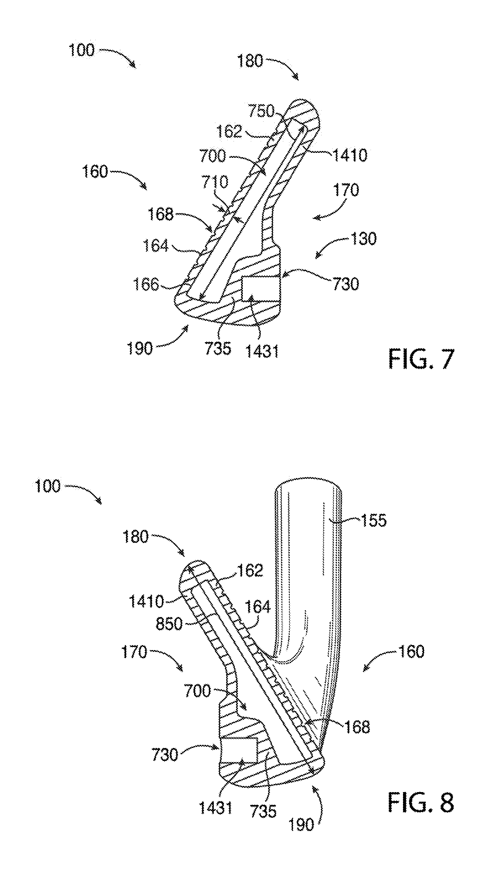
FIG. 7 depicts a cross-sectional view of the example golf club head of FIG. 1 along line 7-7.
FIG. 8 depicts a cross-sectional view of the example golf club head of FIG. 1 along line 8-8.
FIG. 9 depicts a cross-sectional view of the example golf club head of FIG. 1 along line 9-9.
FIG. 10 depicts another rear view of the example golf club head of FIG. 1.
FIG. 11 depicts a top view of a mass portion associated with the example golf club head of FIG. 1.
FIG. 12 depicts a side view of a mass portion associated with the example golf club head of FIG. 1.
FIG. 13 depicts a side view of another mass portion associated with the example golf club head of FIG. 1.
FIG. 14 depicts a rear view of a body portion of the example golf club head of FIG. 1.
FIG. 15 depicts a cross-sectional view of a face portion of the example golf club head of FIG. 1.
FIG. 16 depicts a cross-sectional view of another face portion of the example golf club head of FIG. 1.
FIG. 17 depicts one manner in which the example golf club head described herein may be manufactured.
FIG. 18 depicts another cross-sectional view of the example golf club head of FIG. 4 along line 18-18.
FIG. 19 depicts a schematic cross-sectional view of the example golf club head of FIG. 1.
FIG. 20 depicts another manner in which an example golf club head described herein may be manufactured.
FIG. 21 depicts yet another manner in which an example golf club head described herein may be manufactured.
FIG. 22 depicts a rear view of a golf club head according to an embodiment of the apparatus, methods, and articles of manufacture described herein.
FIG. 23 depicts another rear view of the example golf club head of FIG. 22.
FIG. 24 depicts a front perspective view of a golf club head according to an embodiment of the apparatus, methods, and articles of manufacture described herein.
FIG. 25 depicts a rear perspective view of the example golf club head of FIG. 24.
FIG. 26 depicts heel-side perspective view of the example golf club head of FIG. 24.
FIG. 27 depicts a toe-side perspective view of the example golf club head of FIG. 24 shown without a face portion.
FIG. 28 depicts a front and toe-side perspective view of the example golf club head of FIG. 27.
FIG. 29 depicts a front perspective view of the example golf club head of FIG. 27.
For simplicity and clarity of illustration, the drawing figures illustrate the general manner of construction, and descriptions and details of well-known features and techniques may be omitted to avoid unnecessarily obscuring the present disclosure. Additionally, elements in the drawing figures may not be depicted to scale. For example, the dimensions of some of the elements in the figures may be exaggerated relative to other elements to help improve understanding of embodiments of the present disclosure.
DESCRIPTION
In general, golf club heads and methods to manufacture golf club heads are described herein. The apparatus, methods, and articles of manufacture described herein are not limited in this regard.
In the example of FIGS. 1-14, a golf club head 100 may include a body portion 110 (FIG. 14) having a toe portion 140, a heel portion 150, a front portion 160 with a face portion 162 (e.g., a strike face) having a front surface 164 and a back surface 166, a back portion 170, a top portion 180, and a sole portion 190. The toe portion 140, the heel portion 150, the front portion 160, the back portion 170, the top portion 180, and/or the sole portion 190 may partially overlap each other. For example, a portion of the toe portion 140 may overlap portion(s) of the front portion 160, the back portion 170, the top portion 180, and/or the sole portion 190. In a similar manner, a portion of the heel portion 150 may overlap portion(s) of the front portion 160, the back portion 170, the top portion 180, and/or the sole portion 190. In another example, a portion of the back portion 170 may overlap portion(s) of the toe portion 140, the heel portion 150, the top portion 180, and/or the sole portion 190. The apparatus, methods, and articles of manufacture described herein are not limited in this regard.
The golf club head 100 may be an iron-type golf club head (e.g., a 1-iron, a 2-iron, a 3-iron, a 4-iron, a 5-iron, a 6-iron, a 7-iron, an 8-iron, a 9-iron, etc.) or a wedge-type golf club head (e.g., a pitching wedge, a lob wedge, a sand wedge, an n-degree wedge such as 44 degrees (.degree.), 48.degree., 52.degree., 56.degree., 60.degree., etc.). Although FIGS. 1-10 may depict a particular type of club head, the apparatus, methods, and articles of manufacture described herein may be applicable to other types of club heads (e.g., a driver-type club head, a fairway wood-type club head, a hybrid-type club head, a putter-type club head, etc.). The apparatus, methods, and articles of manufacture described herein are not limited in this regard.
The toe portion 140 may include a portion of the body portion 110 opposite of the heel portion 150. The heel portion 150 may include a hosel portion 155 configured to receive a shaft (not shown) with a grip (not shown) on one end and the golf club head 100 on the opposite end of the shaft to form a golf club. The front surface 164 of the face portion 162 may include one or more score lines, slots, or grooves 168 extending to and/or between the toe portion 140 and the heel portion 150. While the figures may depict a particular number of grooves, the apparatus, methods, and articles of manufacture described herein may include more or less grooves. The face portion 162 may be used to impact a golf ball (not shown). The face portion 162 may be an integral portion of the body portion 110. Alternatively, the face portion 162 may be a separate piece or an insert coupled to the body portion 110 via various manufacturing methods and/or processes (e.g., a bonding process such as adhesive, a welding process such as laser welding, a brazing process, a soldering process, a fusing process, a mechanical locking or connecting method, any combination thereof, or other suitable types of manufacturing methods and/or processes). The face portion 162 may be associated with a loft plane that defines the loft angle of the golf club head 100. The loft angle may vary based on the type of golf club (e.g., a long iron, a middle iron, a short iron, a wedge, etc.). In one example, the loft angle may be between five degrees and seventy-five degrees. In another example, the loft angle may be between twenty degrees and sixty degrees. The apparatus, methods, and articles of manufacture described herein are not limited in this regard.
The back portion 170 may include a portion of the body portion 110 opposite of the front portion 160. In one example, the back portion 170 may be a portion of the body portion 110 behind the back surface 166 of the face portion 162. As shown in FIG. 6, for example, the back portion 170 may be a portion of the body portion 110 behind a plane 171 defined by the back surface 166 of the face portion 162. In another example, the plane 171 may be parallel to the loft plane of the face portion 162. As mentioned above, for example, the face portion 162 may be a separate piece or an insert coupled to the body portion 110. Accordingly, the back portion 170 may include remaining portion(s) of the body portion 110 other than the face portion 162. The apparatus, methods, and articles of manufacture described herein are not limited in this regard.
Further, the body portion 110 may include one or more ports, which may be exterior ports and/or interior ports (e.g., located inside the body portion 110). The interior walls of the body portion 110 may include one or more ports. In one example, the back portion 170 may include one or more ports (e.g., inside an interior cavity, generally shown as 700 in FIG. 7). In another example, the body portion 110 may include one or more ports along a periphery of the body portion 110. As illustrated in FIG. 14, for example, the body portion 110 may include one or more ports on the back portion 170, generally shown as a first set of ports 1420 (e.g., shown as ports 1421, 1422, 1423, and 1424) and a second set of ports 1430 (e.g., shown as ports 1431, 1432, 1433, 1434, 1435, 1436, and 1437). In another example, one or more ports may be on a back wall portion 1410 of the back portion 170. One or more ports may be associated with a port diameter, which may be defined as the largest distance to and/or between opposing ends or boundaries of a port. For example, a port diameter for a rectangular port (e.g., a slot, slit, or elongated rectangular opening) may refer to a diagonal length of a rectangle. In another example, a port diameter of an elliptical port may refer to the major axis of an ellipse. As shown in FIG. 14, for example, each port may have a circular shape with a port diameter equivalent to a diameter of a circle. In one example, the port diameter of the first set of ports 1420 and/or the second set of ports 1430 may be about 0.25 inch (6.35 millimeters). Any two adjacent ports of the first set of ports 1420 may be separated by less than or equal to the port diameter. In a similar manner, any two adjacent ports of the second set of ports 1430 may be separated by less than or equal to the port diameter. Some adjacent ports may be separated by greater than the port diameter. The apparatus, methods, and articles of manufacture described herein are not limited in this regard.
The body portion 110 may include one or more mass portions, which may be integral mass portion(s) or separate mass portion(s) that may be coupled to the body portion 110. In the illustrated example as shown in FIG. 2, the body portion 110 may include a first set of mass portions 120 (e.g., shown as mass portions 121, 122, 123, and 124) and a second set of mass portions 130 (e.g., shown as mass portions 131, 132, 133, 134, 135, 136, and 137). While the above example, may describe a particular number or portions of mass portions, a set of mass portions may include a single mass portion or a plurality of mass portions. For example, the first set of mass portions 120 may be a single mass portion. In a similar manner, the second set of mass portions 130 may be a single mass portion. Further, the first set of mass portions or the second set of mass portions 130 may be a portion of the physical structure of the body portion 110. The apparatus, methods, and articles of manufacture described herein are not limited in this regard.
The body portion 110 may be made of a first material whereas the first set of mass portions 120 and/or the second set of mass portions 130 may be made of a second material. The first and second materials may be similar or different materials. For example, the body portion 110 may be partially or entirely made of a steel-based material (e.g., 17-4 PH stainless steel, Nitronic.RTM. 50 stainless steel, maraging steel or other types of stainless steel), a titanium-based material, an aluminum-based material (e.g., a high-strength aluminum alloy or a composite aluminum alloy coated with a high-strength alloy), any combination thereof, non-metallic materials, composite materials, and/or other suitable types of materials. In one example, one or more mass portions of the first set of mass portions 120 and/or the second set of mass portions 130 may be partially or entirely made of a high-density material such as a tungsten-based material or other suitable types of materials. In another example, one more mass portions of the first set of mass portions 120 and/or the second set of mass portions 130 may be partially or entirely made of other suitable metal material such as a stainless steel-based material, a titanium-based material, an aluminum-based material, any combination thereof, and/or other suitable types of materials. Further, one or more mass portions of the first set of mass portions 120 and/or the second set of mass portions 130 may be made of different types of materials (e.g., metal core and polymer sleeve surrounding the metal core). The body portion 110, the first set of mass portions 120, and/or the second set of mass portions 130 may be partially or entirely made of similar or different non-metal materials (e.g., composite, plastic, polymer, etc.). The apparatus, methods, and articles of manufacture are not limited in this regard.
One or more ports may be configured to receive a mass portion having a similar shape as the port. For example, a rectangular port may receive a rectangular mass portion. In another example, an elliptical port may receive an elliptical mass portion. As shown in FIGS. 10 and 14, for example, the first and second sets of ports 1420 and 1430, respectively, may be cylindrical ports configured to receive one or more cylindrical mass portions. In particular, one or more mass portions of the first set 120 (e.g., generally shown as mass portions 121, 122, 123, and 124) may be disposed in a port located at or proximate to the toe portion 140 and/or the top portion 180. For example, the mass portion 121 may be partially or entirely disposed in the port 1421. One or more mass portions of the second set 130 (e.g., generally shown as mass portions 131, 132, 133, 134, 135, 136, and 137) may be disposed in a port located at or proximate to the toe portion 140 and/or the sole portion 190. For example, the mass portion 135 may be partially or entirely disposed in the port 1435. The first set of mass portions 120 and/or the second set of mass portions 130 may be coupled to the body portion 110 with various manufacturing methods and/or processes (e.g., a bonding process, a welding process, a brazing process, a mechanical locking method, any combination thereof, or other suitable manufacturing methods and/or processes).
Alternatively, the golf club head 100 may not include (i) the first set of mass portions 120, (ii) the second set of mass portions 130, or (iii) both the first and second sets of mass portions 120 and 130, respectively. In particular, the body portion 110 may not include ports at or proximate to the top portion 180 and/or the sole portion 190. For example, the mass of the first set of mass portions 120 (e.g., 3 grams) and/or the mass of the second set of mass portions 130 (e.g., 16.8 grams) may be integral part(s) of the body portion 110 instead of separate mass portion(s). In one example, the body portion 110 may include interior and/or exterior integral mass portions at or proximate to the toe portion 140 and/or at or proximate to the heel portion 150. In another example, a portion of the body portion 110 may include interior and/or exterior integral mass portions extending to and/or between the toe portion 140 and the heel portion 150. The first and/or second set of mass portions 120 and 130, respectively, may affect the mass, the center of gravity (CG), the moment of inertia (MOI), or other physical properties of the golf club head 100. The apparatus, methods, and articles of manufacture described herein are not limited in this regard.
One or more mass portions of the first set of mass portions 120 and/or the second set of mass portions 130 may have similar or different physical properties (e.g., color, marking, shape, size, density, mass, volume, external surface texture, materials of construction, etc.). Accordingly, the first set of mass portions 120 and/or the second set of mass portions 130 may contribute to the ornamental design of the golf club head 100. In the illustrated example as shown in FIG. 11, one or more mass portions of the first set of mass portions 120 and/or the second set of mass portions 130 may have a cylindrical shape (e.g., a circular cross section). Alternatively, one or more mass portions of the first set 120 may have a first shape (e.g., a cylindrical shape) whereas one or more mass portions of the second set 130 may have a second shape (e.g., a cubical shape). In another example, the first set of mass portions 120 may include two or more mass portions with different shapes (e.g., the mass portion 121 may be a first shape whereas the mass portion 122 may be a second shape different from the first shape). Likewise, the second set of mass portions 130 may also include two or more mass portions with different shapes (e.g., the mass portion 131 may be a first shape whereas the mass portion 132 may be a second shape different from the first shape). In another example, one or more mass portions of the first set of mass portions 120 and/or the second set of mass portions 130 may have a different color(s), marking(s), shape(s), density or densities, mass(es), volume(s), material(s) of construction, external surface texture(s), and/or any other physical property as compared to one or more mass portions of the first set of mass portions 120 and/or the second set of mass portions 130. The apparatus, methods, and articles of manufacture described herein are not limited in this regard.
Although the above examples may describe mass portions having a particular shape, the apparatus, methods, and articles of manufacture described herein may include mass portions of other suitable shapes (e.g., a portion of or a whole sphere, cube, cone, cylinder, pyramid, cuboidal, prism, frustum, rectangular, elliptical, or other suitable geometric shape). While the above examples and figures may depict multiple mass portions as a set of mass portions, two or more mass portions of the first set of mass portions 120 and/or the second set of mass portions 130 may be a single piece of mass portion. In one example, the first set of mass portions 120 may be a single piece of mass portion instead of a series of four separate mass portions. In another example, the second set of mass portions 130 may be a single piece of mass portion instead of a series of seven separate mass portions. The apparatus, methods, and articles of manufacture described herein are not limited in this regard.
Referring to FIGS. 12 and 13, for example, the first set of mass portions 120 and/or the second set of mass portions 130 may include threads, generally shown as 1210 and 1310, respectively, to engage with correspondingly configured threads in the ports to secure in the ports of the back portion 170 (e.g., generally shown as 1420 and 1430 in FIG. 14). Accordingly, one or more mass portions as described herein may be shaped similar to and function as a screw or threaded fastener for engaging threads in a port. For example, one or more mass portions of the first set of mass portions 120 and/or the second set of mass portions 130 may be a screw. One or more mass portions of the first set of mass portions 120 and/or the second set of mass portions 130 may not be readily removable from the body portion 110 with or without a tool. Alternatively, one or more mass portions of the first set of mass portions 120 and/or the second set of mass portions 130 may be readily removable (e.g., with a tool) so that a relatively heavier or lighter mass portion may replace one or more mass portions of the first and second sets of mass portions 120 and 130, respectively. In another example, one or more mass portions of the first set of mass portions 120 and/or the second set of mass portions 130 may be secured in the ports of the back portion 170 with epoxy or adhesive so that the one or more mass portions of the first set of mass portions 120 and/or the second set of mass portions 130 may not be readily removable. In yet another example, one or more mass portions of the first set of mass portions 120 and/or the second set of mass portions 130 may be secured in the ports of the back portion 170 with both epoxy and threads so that the one more mass portions of the first set of mass portions 120 and/or the second set of mass portions 130 may not be readily removable. In yet another example, one or more mass portions described herein may be press fit in a port. In yet another example, one or more mass portions described herein may be formed inside a port by injection molding. For example, a liquid metallic material (i.e., molten metal) or a plastic material (e.g. rubber, foam, or any polymer material) may be injected into a port. After the liquid material is cooled and/or cured inside the port, the resulting solid material (e.g., a metal material, a plastic material, or a combination thereof), may be a mass portion. The apparatus, methods, and articles of manufacture described herein are not limited in this regard.
As mentioned above, one or more mass portions of the first set of mass portions 120 and/or the second set of mass portions 130 may be similar in some physical properties but different in other physical properties. For example, a mass portion may be made from an aluminum-based material or an aluminum alloy whereas another mass portion may be made from a tungsten-based material or a tungsten alloy. In another example, a mass portion may be made from a polymer material whereas another mass portion may be made from a steel-based material. In yet another example, as illustrated in FIGS. 11-13, one or more mass portions of the first set of mass portions 120 and/or the second set of mass portions 130 may have a diameter 1110 of about 0.25 inch (6.35 millimeters) but one or more mass portions of the first set of mass portions 120 and/or the second set of mass portions 130 may be different in height. In particular, one or more mass portions of the first set of mass portions 120 may be associated with a first height 1220 (FIG. 12), and one or more mass portions of the second set of mass portions 130 may be associated with a second height 1320 (FIG. 13). The first height 1220 may be relatively shorter than the second height 1320. In one example, the first height 1220 may be about 0.125 inch (3.175 millimeters) whereas the second height 1320 may be about 0.3 inch (7.62 millimeters). In another example, the first height 1220 may be about 0.16 inch (4.064 millimeters) whereas the second height 1320 may be about 0.4 inch (10.16 millimeters). Alternatively, the first height 1220 may be equal to or greater than the second height 1320. Although the above examples may describe particular dimensions, one or more mass portions described herein may have different dimensions. The apparatus, methods, and articles of manufacture described herein are not limited in this regard.
Referring to FIG. 10, for example, the golf club head 100 may be associated with a ground plane 1010, a horizontal midplane 1020, and a top plane 1030. In particular, the ground plane 1010 may be a tangential plane to the sole portion 190 of the golf club head 100 when the golf club head 100 is at an address position (e.g., the golf club head 100 is aligned to strike a golf ball). A top plane 1030 may be a tangential plane to the top portion of the 180 of the golf club head 100 when the golf club head 100 is at the address position. The ground and top planes 1010 and 1030, respectively, may be substantially parallel to each other. The horizontal midplane 1020 may be vertically halfway between the ground and top planes 1010 and 1030, respectively.
The body portion 110 may include any number of ports (e.g., no ports, one port, two ports, etc.) above the horizontal midplane 1020 and/or below the horizontal midplane 1020. In one example, the body portion 110 may include a greater number of ports below the horizontal midplane 1020 than above the horizontal midplane 1020. In the illustrated example as shown in FIG. 14, the body portion 110 may include four ports (e.g., generally shown as ports 1421, 1422, 1423, and 1424) above the horizontal midplane 1020 and seven ports (e.g., generally shown as ports 1431, 1432, 1433, 1434, 1435, 1436, and 1437) below the horizontal midplane 1020. In another example (not shown), the body portion 110 may include two ports above the horizontal midplane 1020 and five ports below the horizontal midplane 1020. In yet another example (not shown), the body portion 110 may not have any ports above the horizontal midplane 1020 but have one or more ports below the horizontal midplane 1020. Accordingly, the body portion 110 may have more ports below the horizontal midplane 1020 than above the horizontal midplane 1020. Further, the body portion 110 may include a port at or proximate to the horizontal midplane 1020 with a portion of the port above the horizontal midplane 1020 and a portion of the port below the horizontal midplane 1020. Accordingly, the port may be (i) above the horizontal midplane 1020, (ii) below the horizontal midplane 1020, or (iii) both above and below the horizontal midplane 1020. The apparatus, methods, and articles of manufacture described herein are not limited in this regard.
To provide optimal perimeter weighting for the golf club head 100, the first set of mass portions 120 (e.g., generally shown as mass portions 121, 122, 123, and 124) may be configured to counter-balance the mass of the hosel 155. For example, as shown in FIG. 10, the first set of mass portions 120 (e.g., generally shown as mass portions 121, 122, 123 and 124) may be located at or near the periphery of the body portion 110 and extend to and/or between the top portion 180 and the toe portion 140. In other words, the first set of mass portions 120 may be located on the golf club head 100 at a generally opposite location relative to the hosel 155. In another example, at least a portion of the first set of mass portions 120 may extend at or near the periphery of the body portion 110 and extend along a portion of the top portion 180. In yet another example, at least a portion of the first set of mass portions 120 may extend at or near the periphery of the body portion 110 and extend along a portion of the toe portion 140. Further, the first set of mass portions 120 may be above the horizontal midplane 1020 of the golf club head 100. For example, the first set of mass portions 120 may be at or near the horizontal midplane 1020. In another example, a portion of the first set of mass portions 120 may be at or above the horizontal midplane 1020 and another portion of the first set of mass portions 120 may be at or below the horizontal midplane 1020. Accordingly, a set of mass portions, which may be a single mass portion, may have portions above the horizontal midplane 1020 and below the horizontal midplane 1020. The apparatus, methods, and articles of manufacture described herein are not limited in this regard.
At least a portion of the first set of mass portions 120 may be at or near the toe portion 140 to increase the MOI of the golf club head 100 about a vertical axis of the golf club head 100 that extends through the CG of the golf club head 100. Accordingly, the first set of mass portions 120 may be at or near the periphery of the body portion 110 and extend through the top portion 180 and/or the toe portion 140 to counter-balance the mass of the hosel 155 and/or increase the MOI of the golf club head 100. The locations of the first set of mass portions 120 (i.e., the locations of the first set of ports 1420) and the physical properties and materials of construction of the first set of mass portions 120 may be determined to optimally affect the mass, mass distribution, CG, MOI, structural integrity and/or or other static and/or dynamic characteristics of the golf club head 100. The apparatus, methods, and articles of manufacture described herein are not limited in this regard.
The second set of mass portions 130 (e.g., generally shown as mass portions 131, 132, 133, 134, 135, 136, and 137) may be configured to place the CG of the golf club head 100 at an optimal location and optimize the MOI of the golf club head 100. Referring to FIG. 10, all or a substantial portion of the second set of mass portions 130 may be generally at or near the sole portion 190. For example, the second set of mass portions 130 (e.g., generally shown as mass portions 131, 132, 133, 134, 135, 136, and 137) may be at or near the periphery of the body portion 110 and extend from the sole portion 190 to the toe portion 140. As shown in the example of FIG. 10, the mass portions 131, 132, 133, and 134 may be located at or near the periphery of the body portion 110 and extend along the sole portion 190 to lower the CG of the golf club head 100. The mass portions 135, 136 and 137 may be located at or near the periphery of the body portion 110 and extend to and/or between the sole portion 190 and the toe portion 140 to lower the CG and increase the MOI of the golf club head 100. For example, the MOI of the golf club head 100 about a vertical axis extending through the CG may increase. To lower the CG of the golf club head 100, all or a portion of the second set of mass portions 130 may be located closer to the sole portion 190 than to the horizontal midplane 1020. For example, the mass portions 131, 132, 133, 134, 135, and 136 may be closer to the sole portion 190 than to the horizontal midplane 1020. The locations of the second set of mass portions 130 (i.e., the locations of the second set of ports 1430) and the physical properties and materials of construction of the second set of mass portions 130 may be determined to optimally affect the mass, mass distribution, CG, MOI, structural integrity and/or or other static and/or dynamic characteristics of the golf club head 100. The apparatus, methods, and articles of manufacture described herein are not limited in this regard.
Turning to FIGS. 7-9, for example, one or more mass portions of the first set of mass portions 120 and/or the second set of mass portions 130 may be located away from the back surface 166 of the face portion 162 (e.g., not directly coupled to each other). That is, one or more mass portions of the first set of mass portions 120 and/or the second set of mass portions 130 and the back surface 166 may be partially or entirely separated by an interior cavity 700 of the body portion 110. As shown in FIG. 14, for example, one or more ports of the first and second sets of ports 1420 and 1430 may include an opening (e.g., generally shown as 720 and 730) and a port wall (e.g., generally shown as 725 and 735). The port walls 725 and 735 may be integral portions of the back wall portion 1410 (e.g., a section of the back wall portion 1410) or the body portion 110 depending on the location of each port. The opening 720 may be configured to receive a mass portion such as mass portion 121. The opening 730 may be configured to receive a mass portion such as mass portion 135. The opening 720 may be located at one end of the port 1421, and the port wall 725 may be located or proximate to at an opposite end of the port 1421. In a similar manner, the opening 730 may be located at one end of the port 1435, and the port wall 735 may be located at or proximate to an opposite end of the port 1435. The port walls 725 and 735 may be separated from the face portion 162 (e.g., separated by the interior cavity 700). The port wall 725 may have a distance 726 from the back surface 166 of the face portion 162 as shown in FIG. 9. The port wall 735 may have a distance 736 from the back surface 166 of the face portion 162. The distances 726 and 736 may be determined to optimize the location of the CG of the golf club head 100 when the first and second sets of ports 1420 and 1430, respectively, receive mass portions as described herein. According to one example, the distance 736 may be greater than the distance 726 so that the CG of the golf club head 100 may be moved toward the back portion 170. As a result, a width 740 of a portion of the interior cavity 700 below the horizontal midplane 1020 may be greater than a width 742 of the interior cavity 700 above the horizontal midplane 1020. The apparatus, methods, and articles of manufacture described herein are not limited in this regard.
As described herein, the CG of the golf club head 100 may be relatively farther back away from the face portion 162 and relatively lower towards a ground plane (e.g., one shown as 1010 in FIG. 10) with all or a substantial portion of the second set of mass portions 130 being at or closer to the sole portion 190 than to the horizontal midplane 1020 and the first and second sets of mass portions 120 and 130, respectively being away from the back surface 166 than if the second set of mass portions 130 were directly coupled to the back surface 166. The body portion 110 may include any number of mass portions (e.g., no mass portions, one mass portion, two mass portions, etc.) and/or any configuration of mass portions (e.g., mass portion(s) integral with the body portion 110) above the horizontal midplane 1020 and/or below the horizontal midplane 1020. The locations of the first and second sets of ports 1420 and 1430 and/or the locations (e.g., internal mass portion(s), external mass portion(s), mass portion(s) integral with the body portion 110, etc.), physical properties and materials of construction of the first set of mass portions 120 and/or the second set of mass portions 130 may be determined to optimally affect the mass, mass distribution, CG, MOI characteristics, structural integrity and/or or other static and/or dynamic characteristics of the golf club head 100. Different from other golf club head designs, the interior cavity 700 of the body portion 110 and the location of the first set of mass portions 120 and/or the second set of mass portion 130 along the periphery of the golf club head 100 may result in a golf ball traveling away from the face portion 162 at a relatively higher ball launch angle and a relatively lower spin rate. As a result, the golf ball may travel farther (i.e., greater total distance, which includes carry and roll distances). The apparatus, methods, and articles of manufacture described herein are not limited in this regard.
While the figures may depict ports with a particular cross-section shape, the apparatus, methods, and articles of manufacture described herein may include ports with other suitable cross-section shapes. In one example, the ports of the first and/or second sets of ports 1420 and 1430 may have U-like cross-section shape. In another example, the ports of the first and/or second set of ports 1420 and 1430 may have V-like cross-section shape. One or more of the ports associated with the first set of mass portions 120 may have a different cross-section shape than one or more ports associated with the second set of mass portions 130. For example, the port 1421 may have a U-like cross-section shape whereas the port 1435 may have a V-like cross-section shape. Further, two or more ports associated with the first set of mass portions 120 may have different cross-section shapes. In a similar manner, two or more ports associated with the second set of mass portions 130 may have different cross-section shapes. The apparatus, methods, and articles of manufacture described herein are not limited in this regard.
The first and second sets of mass portions 120 and 130, respectively, may be similar in mass (e.g., all of the mass portions of the first and second sets 120 and 130, respectively, weigh about the same). Alternatively, the first and second sets of mass portions 120 and 130, respectively, may be different in mass individually or as an entire set. In particular, one or more mass portions of the first set of mass portions 120 (e.g., generally shown as 121, 122, 123, and 124) may have relatively less mass than one or more portions of the second set of mass portions 130 (e.g., generally shown as 131, 132, 133, 134, 135, 136, and 137). For example, the second set of mass portions 130 may account for more than 50% of the total mass from mass portions of the golf club head 100. As a result, the golf club head 100 may be configured to have at least 50% of the total mass from mass portions disposed below the horizontal midplane 1020. Two or more mass portions in the same set may be different in mass. In one example, the mass portion 121 of the first set 120 may have a relatively lower mass than the mass portion 122 of the first set 120. In another example, the mass portion 131 of the second set 130 may have a relatively lower mass than the mass portion 135 of the second set 130. Accordingly, more mass may be distributed away from the CG of the golf club head 100 to increase the MOI about the vertical axis through the CG. The apparatus, methods, and articles of manufacture described herein are not limited in this regard.
In one example, the golf club head 100 may have a mass in the range of about 220 grams to about 330 grams based on the type of golf club (e.g., a 4-iron versus a lob wedge). The body portion 110 may have a mass in the range of about 200 grams to about 310 grams with the first set of mass portions 120 and/or the second set of mass portions 130 having a mass of about 20 grams (e.g., a total mass from mass portions). One or more mass portions of the first set of mass portions 120 and/or the second set of mass portions 130 may have a mass greater than or equal to about 0.1 gram and less than or equal to about 20 grams. In one example, one or more mass portions of the first set 120 may have a mass of about 0.75 gram whereas one or more mass portions of the second set 130 may have a mass of about 2.4 grams. The sum of the mass of the first set of mass portions 120 or the sum of the mass of the second set of mass portions 130 may be greater than or equal to about 0.1 grams and less than or equal to about 20 grams. In one example, the sum of the mass of the first set of mass portions 120 may be about 3 grams whereas the sum of the mass of the first set of mass portions 130 may be about 16.8 grams. The total mass of the second set of mass portions 130 may weigh more than five times as much as the total mass of the first set of mass portions 120 (e.g., a total mass of the second set of mass portions 130 of about 16.8 grams versus a total mass of the first set of mass portions 120 of about 3 grams). The golf club head 100 may have a total mass of 19.8 grams from the first and second sets of mass portions 120 and 130, respectively (e.g., sum of 3 grams from the first set of mass portions 120 and 16.8 grams from the second set of mass portions 130). Accordingly, in one example, the first set of mass portions 120 may account for about 15% of the total mass from mass portions of the golf club head 100 whereas the second set of mass portions 130 may be account for about 85% of the total mass from mass portions of the golf club head 100. The apparatus, methods, and articles of manufacture described herein are not limited in this regard.
By coupling the first set of mass portions 120 and/or the second set of mass portions 130, respectively, to the body portion 110 (e.g., securing the first set of mass portions 120 and/or the second set of mass portions 130 in the ports on the back portion 170), the location of the CG and the MOI) of the golf club head 100 may be optimized. In particular, as described herein, the first set of mass portions 120 may lower the location of the CG towards the sole portion 190 and further back away from the face portion 162. Further, the first set of mass portions 120 and/or the second set of mass portions 130 may increase the MOI as measured about a vertical axis extending through the CG (e.g., perpendicular to the ground plane 1010). The MOI may also be higher as measured about a horizontal axis extending through the CG (e.g., extending towards the toe and heel portions 150 and 160, respectively, of the golf club head 100). As a result, the club head 100 may provide a relatively higher launch angle and a relatively lower spin rate than a golf club head without the first and/or second sets of mass portions 120 and 130, respectively. The apparatus, methods, and articles of manufacture described herein are not limited in this regard.
Although the figures may depict the mass portions as separate and individual parts that may be visible from an exterior of the golf club head 100, the two or more mass portions of the first set of mass portions 120 and/or the second set of mass portions 130 may be a single piece of mass portion that may be an exterior mass portion or an interior mass portion (i.e., not visible from an exterior of the golf club head 100). In one example, all of the mass portions of the first set 120 (e.g., generally shown as 121, 122, 123, and 124) may be combined into a single piece of mass portion (e.g., a first mass portion). In a similar manner, all of the mass portions of the second set 130 (e.g., generally shown as 131, 132, 133, 134, 135, 136, and 137) may be combined into a single piece of mass portion as well (e.g., a second mass portion). In this example, the golf club head 100 may have only two mass portions. In another example (not shown), the body portion 110 may not include the first set of mass portions 120, but include the second set of mass portions 130 in the form of a single piece of internal mass portion that may be farther from the heel portion 150 than the toe portion 140. In yet another example (not shown), the body portion 110 may not include the first set of mass portions 120, but include the second set of mass portions 130 with a first internal mass portion farther from the heel portion 150 than the toe portion 140 and a second internal mass portion farther from the toe portion 140 than from the heel portion 150. The first internal mass portion and the second internal mass portion may be (i) integral parts of the body portion 110 or (ii) separate from the body portion 110 and coupled to the body portion 110. The apparatus, methods, and articles of manufacture described herein are not limited in this regard.
While the figures may depict a particular number of mass portions, the apparatus, methods, and articles of manufacture described herein may include more or less number of mass portions. In one example, the first set of mass portions 120 may include two separate mass portions instead of three separate mass portions as shown in the figures. In another example, the second set of mass portions 130 may include five separate mass portions instead of seven separate mass portions as shown in the figures. Alternatively as mentioned above, the apparatus, methods, and articles of manufacture described herein may not include any separate mass portions (e.g., the body portion 110 may be manufactured to include the mass of the separate mass portions as integral part(s) of the body portion 110). The apparatus, methods, and articles of manufacture described herein are not limited in this regard.
Referring to FIGS. 7-9, for example, the body portion 110 may be a hollow body including the interior cavity 700 extending between the front portion 160 and the back portion 170. Further, the interior cavity 700 may extend between the top portion 180 and the sole portion 190. The interior cavity 700 may be associated with a cavity height 750 (H.sub.C), and the body portion 110 may be associated with a body height 850 (H.sub.B). While the cavity height 750 and the body height 850 may vary between the toe and heel portions 140 and 150, the cavity height 750 may be at least 50% of a body height 850 (H.sub.C>0.5*H.sub.B). For example, the cavity height 750 may vary between 70%-85% of the body height 850. With the cavity height 750 of the interior cavity 700 being greater than 50% of the body height 850, the golf club head 100 may produce relatively more consistent feel, sound, and/or result when the golf club head 100 strikes a golf ball via the face portion 162 than a golf club head with a cavity height of less than 50% of the body height. The apparatus, methods, and articles of manufacture described herein are not limited in this regard.
In one example, the interior cavity 700 may be unfilled (i.e., empty space). The body portion 110 with the interior cavity 700 may weigh about 100 grams less than the body portion 110 without the interior cavity 700. Alternatively, the interior cavity 700 may be partially or entirely filled with a filler material (i.e., a cavity filling portion), which may include one or more similar or different types of materials. In one example, the filler material may include an elastic polymer or an elastomer material (e.g., a viscoelastic urethane polymer material such as Sorbothane.RTM. material manufactured by Sorbothane, Inc., Kent, Ohio), a thermoplastic elastomer material (TPE), a thermoplastic polyurethane material (TPU), other polymer material(s), bonding material(s) (e.g., adhesive), and/or other suitable types of materials that may absorb shock, isolate vibration, and/or dampen noise. For example, at least 50% of the interior cavity 700 may be filled with a TPE material to absorb shock, isolate vibration, and/or dampen noise when the golf club head 100 strikes a golf ball via the face portion 162. The apparatus, methods, and articles of manufacture described herein are not limited in this regard.
In another example, the filler material may be a polymer material such as an ethylene copolymer material that may absorb shock, isolate vibration, and/or dampen noise when the golf club head 100 strikes a golf ball via the face portion 162. In particular, at least 50% of the interior cavity 700 may be filled with a high density ethylene copolymer ionomer, a fatty acid modified ethylene copolymer ionomer, a highly amorphous ethylene copolymer ionomer, an ionomer of ethylene acid acrylate terpolymer, an ethylene copolymer comprising a magnesium ionomer, an injection moldable ethylene copolymer that may be used in conventional injection molding equipment to create various shapes, an ethylene copolymer that can be used in conventional extrusion equipment to create various shapes, an ethylene copolymer having high compression and low resilience similar to thermoset polybutadiene rubbers, and/or a blend of highly neutralized polymer compositions, highly neutralized acid polymers or highly neutralized acid polymer compositions, and fillers. For example, the ethylene copolymer may include any of the ethylene copolymers associated with DuPont.TM. High-Performance Resin (HPF) family of materials (e.g., DuPont.TM. HPF AD1172, DuPont.TM. HPF AD1035, DuPont.RTM. HPF 1000 and DuPont.TM. HPF 2000), which are manufactured by E.I. du Pont de Nemours and Company of Wilmington, Del. The DuPont.TM. HPF family of ethylene copolymers are injection moldable and may be used with conventional injection molding equipment and molds, provide low compression, and provide high resilience, i.e., relatively high coefficient of restitution (COR). The apparatus, methods, and articles of manufacture described herein are not limited in this regard.
For example, the filler material may have a density of less than or equal to 1.5 g/cm.sup.3. The filler material may have a compression deformation value ranging from about 0.0787 inch (2 mm) to about 0.1968 inch (5 mm). The filler material may have a surface Shore D hardness ranging from 40 to 60. As mentioned above, the filler material may be associated with a relatively high coefficient of restitution (COR). The filler material may be associated with a first COR (COR.sub.1) and the face portion 2462 may be associated with a second COR (COR.sub.2), which may be similar or different from the first COR. The first and second CORs may be associated with a COR ratio (e.g., COR.sub.12 ratio=COR.sub.1/COR.sub.2 or COR.sub.21 ratio=COR.sub.2/COR.sub.1). In one example, the COR ratio may be less than two (2). In another example, the COR ratio may be in a range from about 0.5 to about 1.5. In yet another example, the COR ratio may be in a range from about 0.8 to about 1.2. The apparatus, methods, and articles of manufacture described herein are not limited in this regard.
The golf club head 100 may be associated with a third COR (COR.sub.3), which may be similar or different from the first COR and/or the second COR. As mentioned above, the filler material may be associated with the first COR. The first and third CORs may be associated with a COR ratio (e.g., COR.sub.13 ratio=COR.sub.1/COR.sub.3 or COR.sub.31 ratio=COR.sub.3/COR.sub.1). In one example, the COR ratio may be less than two (2). In another example, the COR ratio may be in a range from about 0.5 to about 1.5. In yet another example, the COR ratio may be in a range from about 0.8 to about 1.2. The apparatus, methods, and articles of manufacture described herein are not limited in this regard.
The CORs of the filler material, the face portion 162, and/or the golf club head 100 (e.g., the first COR (COR.sub.1), the second COR (COR.sub.2), and/or the third COR (COR.sub.3), respectively) may be measured by methods similar to methods that measure the COR of a golf ball and/or a golf club head as defined by one or more golf standard organizations and/or governing bodies (e.g., United States Golf Association (USGA)). In one example, an air cannon device may launch or eject an approximately 1.55 inch (38.1 mm) spherical sample of the filler material at an initial velocity toward a steel plate positioned at about 4 feet (1.2 meters) away from the air cannon device. The sample may vary in size, shape or any other configuration. A speed monitoring device may be located at a distance in a range from 2 feet (0.6 meters) to 3 feet (0.9 meters) from the air cannon device. The speed monitoring device may measure a rebound velocity of the sample of the filler material after the sample of the filler material strikes the steel plate. The COR may be the rebound velocity divided by the initial velocity. In one example, the filler material may have a COR value in a range from approximately 0.50 to approximately 0.95 when measured with an initial velocity in a range from 100 ft/s (30.48 m/s) to 250 ft/s (76.2 m/s). In another example, the filler material may have a COR value in a range from approximately 0.65 to approximately 0.85 when measured with an initial velocity in a range from 100 ft/s (30.48 m/s) to 150 ft/s (45.72 m/s). In another example, the filler material may have a COR value in a range from approximately 0.75 to approximately 0.8 when measured with an initial velocity in a range 100 ft/s (30.48 m/s) to 150 ft/s (45.72 m/s). In another example, the filler material may have a COR value in a range from approximately 0.55 to approximately 0.90 when measured with an initial velocity in a range from 100 ft/s (30.48 m/s) and 250 ft/s (76.2 m/s). In another example, the filler material may have a COR value in a range from approximately 0.75 to approximately 0.85 when measured with an initial velocity in a range 110 ft/s (33.53 m/s) to 200 ft/s (60.96 m/s). In yet another example, the filler material may have a COR value in a range from approximately 0.8 to approximately 0.9 when measured with an initial velocity of about 125 ft/s (38.1 m/s). While a particular example may be described above, other methods may be used to measure the CORs of the filler material, the face portion 162, and/or the golf club head 100. The apparatus, methods, and articles of manufacture described herein are not limited in this regard.
When the face portion 162 of the golf club head 100 strikes a golf ball, the face portion 162 and the filler material may deform and/or compress. The kinetic energy of the impact may be transferred to the face portion 162 and/or the filler material. For example, some of the kinetic energy may be transformed into heat by the filler material or work done in deforming and/or compressing the filler material. Further, some of the kinetic energy may be transferred back to the golf ball to launch the golf ball at a certain velocity. A filler material with a relatively higher COR may transfer relatively more kinetic energy to the golf ball and dissipate relatively less kinetic energy. Accordingly, a filler material with a relatively high COR may generate relatively higher golf ball speeds because a relatively greater part of the kinetic energy of the impact may be transferred back to the golf ball to launch the golf ball from the golf club head 100.
The filler material may include a bonding portion. In one example, the bonding portion may be one or more bonding agents (e.g., one or more adhesive or epoxy materials). For example, the bonding agent may assist in bonding or adhering the filler material to at least the back surface 166 of the face portion 162. The bonding agent may also absorb shock, isolate vibration, and/or dampen noise when the golf club head 100 strikes a golf ball via the face portion 162. Further, the bonding agent may be an epoxy material that may be flexible or slightly flexible when cured. In one example, the filler material may include any of the 3M.TM. Scotch-Weld.TM. DP100 family of epoxy adhesives (e.g., 3M.TM. Scotch-Weld.TM. Epoxy Adhesives DP100, DP100 Plus, DP100NS and DP100FR), which are manufactured by 3M corporation of St. Paul, Minn. In another example, the filler material may include 3M.TM. Scotch-Weld.TM. DP100 Plus Clear adhesive. In yet another example, the filler material may include low-viscosity, organic, solvent-based solutions and/or dispersions of polymers and other reactive chemicals such as MEGUM.TM., ROBOND.TM. and/or THIXON.TM. materials manufactured by the Dow Chemical Company, Auburn Hills, Mich. In yet another example, the filler material may be LOCTITE.RTM. materials manufactured by Henkel Corporation, Rocky Hill, Conn. The apparatus, methods, and articles of manufacture described herein are not limited in this regard.
Further, the filler material may include a combination of one or more bonding agents such as any of the bonding agents described herein and one or more polymer materials such as any of the polymer materials described herein. In one example, the filler material may include one or more bonding agents that may be used to bond the polymer material to the back surface 166 of the face portion 162. The one or more bonding agents may be applied to the back surface 166 of the face portion 162. The filler material may further include one or more polymer materials may partially or entirely fill the remaining portions of the interior cavity 700. Accordingly, two or more separate materials may partially or entirely fill the interior cavity 700. The apparatus, methods, and articles of manufacture described herein are not limited in this regard.
The filler material may only include one or more polymer materials that adhere to inner surface(s) of the interior cavity 700 without a separate bonding agent (e.g., an adhesive or epoxy material). For example, the filler material may include a mixture of one or more polymer materials and one or more bonding agents (e.g., adhesive or epoxy material(s)). Accordingly, the mixture including the one or more polymer materials and the one or more bonding agents may partially or entirely fill the interior cavity 700 and adhere to inner surface(s) of the interior cavity 700. In another example, the interior cavity 700 may be partially or entirely filled with one or more polymer materials without any bonding agents. In yet another example, the interior cavity 700 may be partially or entirely filled with one or more bonding agents and/or adhesive materials such as an adhesive or epoxy material. The apparatus, methods, and articles of manufacture described herein are not limited in this regard.
Turning to FIG. 15, for example, a thickness of the face portion 162 may be a first thickness 1510 (T.sub.1) or a second thickness 1520 (T.sub.2). The first thickness 1510 may be a thickness of a section of the face portion 162 adjacent to a groove 168 whereas the second thickness 1520 may be a thickness of a section of the face portion 162 below the groove 168. For example, the first thickness 1510 may be a maximum distance between the front surface 164 and the back surface 166. The second thickness 1520 may be based on the groove 168. In particular, the groove 168 may have a groove depth 1525 (D.sub.groove). The second thickness 1520 may be a maximum distance between the bottom of the groove 168 and the back surface 166. The sum of the second thickness 1520 and the groove depth 1525 may be substantially equal to the first thickness 1510 (e.g., T.sub.2+D.sub.groove=T.sub.1). Accordingly, the second thickness 1520 may be less than the first thickness 1510 (e.g., T.sub.2<T.sub.1).
To lower and/or move the CG of the golf club head 100 further back, mass from the front portion 160 of the golf club head 100 may be removed by using a relatively thinner face portion 162. For example, the first thickness 1510 or the second thickness 1520 may be less than or equal to 0.1 inch (2.54 millimeters). In another example, the first thickness 1510 may be about 0.075 inch (1.905 millimeters) (e.g., T.sub.1=0.075 inch). With the support of the back wall portion 1410 to form the interior cavity 700 and filling at least a portion of the interior cavity 700 with an elastic polymer material, the face portion 162 may be relatively thinner (e.g., T.sub.1<0.075 inch) without degrading the structural integrity, sound, and/or feel of the golf club head 100. In one example, the first thickness 1510 may be less than or equal to 0.060 inch (1.524 millimeters) (e.g., T.sub.1.ltoreq.0.060 inch). In another example, the first thickness 1510 may be less than or equal to 0.040 inch (1.016 millimeters) (e.g., T.sub.1.ltoreq.0.040 inch). Based on the type of material(s) used to form the face portion 162 and/or the body portion 110, the face portion 162 may be even thinner with the first thickness 1510 being less than or equal to 0.030 inch (0.762 millimeters) (e.g., T.sub.1.ltoreq.0.030 inch). The groove depth 1525 may be greater than or equal to the second thickness 1520 (e.g., D.sub.groove.gtoreq.T.sub.2). In one example, the groove depth 1525 may be about 0.020 inch (0.508 millimeters) (e.g., D.sub.groove=0.020 inch). Accordingly, the second thickness 1520 may be about 0.010 inch (0.254 millimeters) (e.g., T.sub.2=0.010 inch). In another example, the groove depth 1525 may be about 0.015 inch (0.381 millimeters), and the second thickness 1520 may be about 0.015 inch (e.g., D.sub.groove=T.sub.2=0.015 inch). Alternatively, the groove depth 1525 may be less than the second thickness 1520 (e.g., D.sub.groove<T.sub.2). Without the support of the back wall portion 1410 and the elastic polymer material to fill in the interior cavity 700, a golf club head may not be able to withstand multiple impacts by a golf ball on a face portion. In contrast to the golf club head 100 as described herein, a golf club head with a relatively thin face portion but without the support of the back wall portion 1410 and the elastic polymer material to fill in the interior cavity 700 (e.g., a cavity-back golf club head) may produce unpleasant sound (e.g., a tinny sound) and/or feel during impact with a golf ball. The apparatus, methods, and articles of manufacture described herein are not limited in this regard.
Based on manufacturing processes and methods used to form the golf club head 100, the face portion 162 may include additional material at or proximate to a periphery of the face portion 162. Accordingly, the face portion 162 may also include a third thickness 1530, and a chamfer portion 1540. The third thickness 1530 may be greater than either the first thickness 1510 or the second thickness 1520 (e.g., T.sub.3>T.sub.1>T.sub.2). In particular, the face portion 162 may be coupled to the body portion 110 by a welding process. For example, the first thickness 1510 may be about 0.030 inch (0.762 millimeters), the second thickness 1520 may be about 0.015 inch (0.381 millimeters), and the third thickness 1530 may be about 0.050 inch (1.27 millimeters). Accordingly, the chamfer portion 1540 may accommodate some of the additional material when the face portion 162 is welded to the body portion 110.
As illustrated in FIG. 16, for example, the face portion 162 may include a reinforcement section, generally shown as 1605, below one or more grooves 168. In one example, the face portion 162 may include a reinforcement section 1605 below each groove. Alternatively, face portion 162 may include the reinforcement section 1605 below some grooves (e.g., every other groove) or below only one groove. The face portion 162 may include a first thickness 1610, a second thickness 1620, a third thickness 1630, and a chamfer portion 1640. The groove 168 may have a groove depth 1625. The reinforcement section 1605 may define the second thickness 1620. The first and second thicknesses 1610 and 1620, respectively, may be substantially equal to each other (e.g., T.sub.1=T.sub.2). In one example, the first and second thicknesses 1610 and 1620, respectively, may be about 0.030 inch (0.762 millimeters) (e.g., T.sub.1=T.sub.2=0.030 inch). The groove depth 1625 may be about 0.015 inch (0.381 millimeters), and the third thickness 1630 may be about 0.050 inch (1.27 millimeters). The groove 168 may also have a groove width. The width of the reinforcement section 1605 may be greater than or equal to the groove width. The apparatus, methods, and articles of manufacture described herein are not limited in this regard.
Alternatively, the face portion 162 may vary in thickness at and/or between the top portion 180 and the sole portion 190. In one example, the face portion 162 may be relatively thicker at or proximate to the top portion 180 than at or proximate to the sole portion 190 (e.g., thickness of the face portion 162 may taper from the top portion 180 towards the sole portion 190). In another example, the face portion 162 may be relatively thicker at or proximate to the sole portion 190 than at or proximate to the top portion 180 (e.g., thickness of the face portion 162 may taper from the sole portion 190 towards the top portion 180). In yet another example, the face portion 162 may be relatively thicker between the top portion 180 and the sole portion 190 than at or proximate to the top portion 180 and the sole portion 190 (e.g., thickness of the face portion 162 may have a bell-shaped contour). The apparatus, methods, and articles of manufacture described herein are not limited in this regard. As described herein, the interior cavity 700 may be partially or fully filled with a filler material, which may be a polymer material, a bonding agent (such as an adhesive or epoxy material), or a combination of polymer material(s) and bonding agent(s) to at least partially provide structural support for the face portion 162. In particular, the filler material may also provide vibration and/or noise dampening for the body portion 110 when the face portion 162 strikes a golf ball. Alternatively, the filler material may only provide vibration and/or noise dampening for the body portion 110 when the face portion 162 strikes a golf ball. In one example, the body portion 110 of the golf club head 100 (e.g., an iron type golf club head) may have a body portion volume (V.sub.b) between about 2.0 cubic inches (32.77 cubic centimeters) and about 4.2 cubic inches (68.83 cubic centimeters). The volume of the filler material filling the interior cavity (V.sub.e), such as the interior cavity 700, may be between 0.5 and 1.7 cubic inches (8.19 and 27.86 cubic centimeters, respectively). A ratio of the filler material volume (V.sub.e) to the body portion volume (V.sub.b) may be expressed as:
.ltoreq..ltoreq. ##EQU00001## Where: V.sub.e is the filler material volume in units of in.sup.3, and V.sub.b is the body portion volume in units of in.sup.3.
In another example, the ratio of the filler material volume (V.sub.e) to the body portion volume (V.sub.b) may be between about 0.2 and about 0.4. In yet another example, the ratio of the filler material volume (V.sub.e) to the body portion volume (V.sub.b) may be between about 0.25 and about 0.35. The apparatus, methods, and articles of manufacture described herein are not limited in this regard.
Based on the amount of filler material filling the interior cavity, for example, the thickness of the face portion may be between about 0.025 inches (0.635 millimeters) and about 0.1 inch (2.54 millimeters). In another example, the thickness of the face portion (T.sub.f) may be between about 0.02 inches (0.508 millimeters) and about 0.09 inches (2.286 millimeters). The thickness of the face portion (T.sub.f) may depend on the volume of the filler material in the interior cavity (V.sub.e), such as the interior cavity 700. The ratio of the thickness of the face portion (T.sub.f) to the volume of the filler material (V.sub.e) may be expressed as:
.ltoreq..ltoreq. ##EQU00002## Where: T.sub.f is the thickness of the face portion in units of inches, and V.sub.e is the filler material volume in units of in.sup.3.
In one example, the ratio of the thickness of the face portion (T.sub.f) to the volume of the filler material (V.sub.e) may be between 0.02 and 0.09. In another example, the ratio of the thickness of the face portion (T.sub.f) to the volume of the filler material (V.sub.e) may be between 0.04 and 0.14. The thickness of the face portion (T.sub.f) may be the same as T.sub.1 and/or T.sub.2 mentioned above. The apparatus, methods, and articles of manufacture described herein are not limited in this regard.
The thickness of the face portion (T.sub.f) may depend on the volume of the filler material in the interior cavity (V.sub.e), such as the interior cavity 700, and the body portion volume (V.sub.b). The volume of the filler material (V.sub.e) may be expressed as: V.sub.e=a*V.sub.b+b.+-.c*T.sub.f a.apprxeq.0.48 b.apprxeq.-0.38 0.ltoreq.c.ltoreq.10 Where: V.sub.e is the filler material volume in units of in.sup.3, V.sub.b is the body portion volume in units of in.sup.3, and T.sub.f is the thickness of the face portion in units of inches.
As described herein, for example, the body portion volume (V.sub.b) may be between about 2.0 cubic inches (32.77 cubic centimeters) and about 4.2 cubic inches (68.83 cubic centimeters). In one example, the thickness of the face portion (T.sub.f) may be about 0.03 inches (0.762 millimeters). In another example, the thickness of the face portion (T.sub.f) may be about 0.06 inches (1.524 millimeters). In yet another example, the thickness of the face portion (T.sub.f) may be about 0.075 inches (1.905 millimeters). The apparatus, methods, and articles of manufacture described herein are not limited in this regard.
Further, the volume of the filler material (V.sub.e) when the interior cavity is fully filled with the filler material may be similar to the volume of the interior cavity (V.sub.c). Accordingly, when the interior cavity is fully filled with a filler material, the volume of the filler material (V.sub.e) in any of the equations provided herein may be replaced with the volume of the interior cavity (V.sub.c). Accordingly, the above equations expressed in terms of the volume of the interior cavity (V.sub.c) may be expressed as:
.ltoreq..ltoreq. ##EQU00003## .ltoreq..ltoreq. ##EQU00003.2## .+-. ##EQU00003.3## .apprxeq. ##EQU00003.4## .apprxeq. ##EQU00003.5## .ltoreq..ltoreq. ##EQU00003.6## Where: V.sub.c is the volume of the interior cavity in units of in.sup.3, V.sub.b is the body portion volume in units of in.sup.3, and T.sub.f is the thickness of the face portion in units of inches.
As described herein, the filler material may include a bonding agent that may be bonded to the back surface 166 of the face portion 162 to attach the remaining portions of the filler material to the back surface 166 of the face portion 162, dampen noise and vibration, provide a certain feel and sound for the golf club head, and/or at least partially structurally support the face portion 162. The thickness of the bonding agent and/or a portion of the filler material may depend on a thickness of the face portion 162. In one example, a relationship between a thickness of the face portion 162 and a thickness of a bonding agent and/or a portion of the filler material may be expressed as:
.ltoreq..ltoreq. ##EQU00004## Where: T.sub.f is the thickness of the face portion in units of inches, and T.sub.a is the thickness of the bonding agent and/or the thickness of the filler material in units of inches.
In one example, the bonding agent and/or the filler material may have a thickness ranging from 0.02 inch (0.51 millimeters) to 0.2 inch (5.08 millimeters). In another example, the bonding agent and/or the filler material may be have a thickness ranging from 0.04 inch (0.1.02 millimeters) to 0.08 inch (2.03 millimeters). In another example, the bonding agent and/or the filler material may be have a thickness ranging from 0.03 inch (0.76 millimeters) to 0.06 inch (1.52 millimeters). In yet another example, the bonding agent and/or the filler material may have a thickness ranging from 0.01 inch (0.25 millimeters) to 0.3 inch (7.62 millimeters). The apparatus, methods, and articles of manufacture described herein are not limited in this regard.
FIG. 17 depicts one manner in which the example golf club head described herein may be manufactured. In the example of FIG. 17, the process 1700 may begin with providing one or more mass portions, generally shown as the first and second sets of mass portions 120 and 130, respectively (block 1710). The first set of mass portions 120 and/or the second set of mass portions 130 may be made of a first material such as a tungsten-based material, a titanium-based material, a steel-based material, an aluminum-based material, a non-metal material, any combination thereof, or other suitable type of materials. In one example, the mass portions of the first and second sets 120 and 130, respectively, may be tungsten-alloy screws.
The process 1700 may provide a body portion 110 having the face portion 162, the interior cavity 700, and the back portion 170 with two or more ports, generally shown as 1420 and 1430 (block 1720). The body portion 110 may be made of a second material, which may be different than the first material or similar to the first material. The body portion 110 may be manufactured using an investment casting process, a billet forging process, a stamping process, a computer numerically controlled (CNC) machining process, a die casting process, any combination thereof, or other suitable manufacturing processes. In one example, the body portion 110 may be made of 17-4 PH stainless steel using a casting process. In another example, the body portion 110 may be made of other suitable type of stainless steel (e.g., Nitronic.RTM. 50 stainless steel manufactured by AK Steel Corporation, West Chester, Ohio) using a forging process. By using Nitronic.RTM. 50 stainless steel to manufacture the body portion 110, the golf club head 100 may be relatively stronger and/or more resistant to corrosion than golf club heads made from other types of steel. One or more ports of the body portion 110 may include an opening and a port wall. For example, the port 1421 may include the opening 720 and the port wall 725 with the opening 720 and the port wall 725 being on opposite ends of each other. The interior cavity 700 may separate the port wall 725 of the port 1421 and the back surface 166 of the face portion 162. In a similar manner, the port 1435 may include the opening 730 and the port wall 735 with the opening 730 and the port wall 735 being on opposite ends of each other. The interior cavity 700 may separate the port wall 735 of the port 1435 and the back surface 166 of the face portion 162.
The process 1700 may couple one or more mass portions of the first and second sets of mass portions 120 and 130 into one of the one or more ports (blocks 1730). In one example, the process 1700 may insert and secure the mass portion 121 in the port 1421, and the mass portion 135 in the port 1435. The process 1700 may use various manufacturing methods and/or processes to secure the first set of mass portions 120 and/or the second set of mass portions 130 in the ports such as the ports 1421 and 1435 (e.g., epoxy, welding, brazing, mechanical lock(s), any combination thereof, etc.).
The process 1700 may partially or entirely fill the interior cavity 700 with a filler material, which may be one or a combination of a polymer material (e.g., an ethylene copolymer material such as DuPont.TM. HPF family of materials) (block 1740) and/or a bonding agent (e.g., an adhesive or epoxy material such as 3M.TM. Scotch-Weld.TM. Epoxy Adhesives DP100, DP100 Plus, DP100NS and DP100FR). In one example, the filler material may fill at least 50% of the interior cavity 700. As mentioned above, the filler material may absorb shock, isolate vibration, and/or dampen noise in response to the golf club head 100 striking a golf ball. In one example, the interior cavity 700 may be filled with filler material, which may be a polymer material, a thermoplastic elastomer material, a thermoplastic polyurethane material, a bonding agent, and/or a combination thereof. In another example, the interior cavity 700 may be entirely filled with a bonding agent. As illustrated in FIG. 18, for example, the golf club head 100 may include one or more ports (e.g., one shown as 1431 in FIG. 14) with a first opening 1830 and a second opening 1835. The second opening 1835 may be used to access the interior cavity 700. In one example, the process 1700 (FIG. 17) may fill the interior cavity 700 with a filler material by injecting the filler material into the interior cavity 700 from the first opening 1830 via the second opening 1835. The first and second openings 1830 and 1835, respectively, may be same or different in size and/or shape. While the above example may describe and depict a particular port with a second opening, any other ports of the golf club head 100 may include a second opening (e.g., the port 1421). The apparatus, methods, and articles of manufacture described herein are not limited in this regard.
Referring back to FIG. 17, the example process 1700 is merely provided and described in conjunction with other figures as an example of one way to manufacture the golf club head 100. While a particular order of actions is illustrated in FIG. 17, these actions may be performed in other temporal sequences. For example, two or more actions depicted in FIG. 17 may be performed sequentially, concurrently, or simultaneously. In one example, blocks 1710, 1720, 1730, and/or 1740 may be performed simultaneously or concurrently. Although FIG. 17 depicts a particular number of blocks, the process may not perform one or more blocks. In one example, the interior cavity 700 may not be filled (i.e., block 1740 may not be performed). The apparatus, methods, and articles of manufacture described herein are not limited in this regard. Referring back to FIGS. 1-14, the face portion 162 may include a non-smooth back surface to improve adhesion and/or mitigate delamination between the face portion 162 and the elastic polymer material used to fill the interior cavity 700 (e.g., FIG. 7). Various methods and/or processes such as an abrasive blasting process (e.g., a bead blasting process, a sand blasting process, other suitable blasting process, or any combination thereof) and/or a milling (machining) process may be used to form the back surface 166 into a non-smooth surface. For example, the back surface 166 may have with a surface roughness (Ra) ranging from 0.5 to 250 .mu.in (0.012 to 6.3 .mu.m). The apparatus, methods, and articles of manufacture are not limited in this regard.
Referring to FIG. 19, for example, the golf club head 100 may include the face portion 162, a bonding portion 1910, and a polymer material 1920. The bonding portion 1910 may provide connection, attachment and/or bonding of the polymer material 1920 to the face portion 162. In one example, the bonding portion 1910 and/or the polymer material 1920 may define a filler material as described herein. The bonding portion 1910 may be a bonding agent such as any of adhesive or epoxy materials described herein, a tacky material, a combination of bonding agents, a bonding structure or attachment device (i.e., a physical and/or mechanical structure or device), a combination of bonding structures and/or attachment devices, and/or a combination of one or more bonding agents, one or more bonding structures and/or one or more attachment devices. The bonding portion 1910 may be integral with the polymer material 1920 to partially or entirely fill the interior cavity 700. In other words, the polymer material 1920 may include inherent bonding properties. For example, the bonding portion 1910 may be a bonding agent mixed with the polymer material 1910 to provide bonding of the mixture to the back surface 166 of the face portion 162 and/or other inner surface(s) of the body portion 110. In one example, the bonding portion may include one or more surface textures or surface structures on the back surface 166 of the face portion 162 to assist in adhesion of the polymer material to the back surface 166 of the face portion. The apparatus, methods, and articles of manufacture are not limited in this regard.
For example, the golf club head 100 may include a bonding agent such as any adhesive or epoxy materials described herein to improve adhesion and/or mitigate delamination between the face portion 162 and the polymer material 1920 used to fill the interior cavity 700 of the golf club head 100 (e.g., FIG. 7). The bonding portion 1910 may be applied to the back surface 166 of the face portion 162 to bond the polymer material 1920 to the face portion 162 (e.g., extending between the back surface 166 and the polymer material 1920). For example, the bonding portion 1910 may be applied before or during when the interior cavity 700 is filled with the polymer material 1920 via an injection molding process or other suitable process. The apparatus, methods, and articles of manufacture are not limited in this regard.
FIG. 20 depicts one manner to partially or entirely fill the interior cavity 700 of the golf club head 100 or any of the golf club heads described herein with a filler material. The process 2000 may begin with heating the golf club head 100 to a certain temperature (block 2010). In one example, the golf club head 100 may be heated to a temperature ranging between 150.degree. C. and 250.degree. C., which may depend on factors such as the vaporization temperature of the one or more components of the filler material to be injected in the interior cavity 700. The filler material may then be heated to a certain temperature (block 2020). In one example, the filler material may be a non-foaming and injection-moldable thermoplastic elastomer (TPE) material. Accordingly, the filler material may be heated to reach a liquid or a flowing state prior to being injected into the interior cavity 700. The temperature at which the filler material may be heated may depend on the type of polymer material used to form the filler material. The heated filler material may be injected into the interior cavity 700 to partially or fully fill the interior cavity 700 (block 2030). The filler material may be injected into the interior cavity 700 from one or more of the ports described herein (e.g., one or more ports of the first and second sets of ports 1420 and 1430, respectively, shown in FIG. 14). One or more other ports may allow the air inside the interior cavity 700 displaced by the filler material to vent from the interior cavity 700. In one example, the golf club head 100 may be oriented horizontally as shown in FIG. 14 during the injection molding process. The filler material may be injected into the interior cavity 700 from ports 1431 and 1432. The ports 1421, 1422 and/or 1423 may serve as air ports for venting the displaced air from the interior cavity 700. Thus, regardless of the orientation of the golf club head 100 during the injection molding process, the filler material may be injected into the interior cavity 700 from one or more lower positioned ports while one or more upper positioned ports may serve as air vents. The mold (e.g., the golf club head 100) may then be cooled passively (e.g., at room temperature) or actively so that the filler material reaches a solid state and adheres to the back surface 166 of the face portion 162. The filler material may directly adhere to the back surface 166 of the face portion 162. Alternatively, the filler material may adhere to the back surface 166 of the face portion 162 with the aid of the one or more structures on the back surface 166 and/or the bonding portion 1910 shown in FIG. 19 (e.g., a bonding agent as described herein). The apparatus, methods, and articles of manufacture described herein are not limited in this regard.
As described above, the filler material may be heated to a liquid state (i.e., non-foaming) and solidifies after being injection molded in the interior cavity 700. A filler material with a low modulus of elasticity may provide vibration and/or noise dampening for the face portion 162 when the face portion 162 impacts a golf ball. For example, a polymer material that foams when heated may provide vibration and/or noise dampening. However, such a foaming polymer material may not have sufficient rigidity to provide structural support to a relatively thin face portion because of possible excessive deflection and/or compression of the polymer material when absorbing the impact of a golf ball. In one example, the one or more components of the filler material that is injection molded in the interior cavity 700 may have a relatively high modulus of elasticity to provide structural support to the face portion 162 and yet elastically deflect to absorb the impact forces experienced by the face portion 162 when striking a golf ball. Thus, a non-foaming and injection moldable polymer material with a relatively high modulus of elasticity may be used for partially or entirely filling the interior cavity 700 to provide structural support and reinforcement for the face portion 162 in addition to providing vibration and noise dampening. That is, the non-foaming and injection moldable polymer material may be a structural support portion for the face portion 162. The apparatus, methods, and articles of manufacture are not limited in this regard.
As described herein, the filler material may include a bonding portion. The bonding portion may include an adhesive or epoxy material with a thickness to provide structural support for the face portion 162. Accordingly, the filler material may include a foaming polymer material to provide vibration and noise dampening whereas the bonding portion may provide structural support for the face portion 162. The thickness of the bonding portion may depend on a thickness and physical properties of the face portion 162 as described herein. The apparatus, methods, and articles of manufacture are not limited in this regard.
As described herein, the filler material may include a bonding agent (e.g., an adhesive or epoxy material) and a polymer material. FIG. 21 depicts one manner in which a bonding agent as described herein may be applied to a golf club head prior to partially or entirely filling the interior cavity 700. In the example of FIG. 21, the process 2100 may begin with injecting a bonding agent on the back surface 166 of the face portion 162 (block 2110). The bonding agent may be injected on the back surface 166 prior to or after heating the golf club head as described above depending on the properties of the bonding agent. The bonding agent may be injected through one or more of the first set of ports 1420 and/or the second set of ports 1430. The bonding agent may be injected on the back surface 166 through several or all of the first set of ports 1420 and the second set of ports 1430. For example, an injection instrument such as a nozzle or a needle may be inserted into each port until the tip or outlet of the instrument is near the back surface 166. The bonding agent may then be injected on the back surface 166 from the outlet of the instrument. Additionally, the instrument may be moved, rotated and/or swiveled while inside the interior cavity 700 so that the bonding agent is injected onto an area of the back surface 166 surrounding the instrument. For example, the outlet of the injection instrument may be moved in a circular pattern while inside a port to inject the bonding agent in a corresponding circular pattern on the back surface 166. Each of the first set of ports 1420 and the second set of ports 1430 may be utilized to inject a bonding agent on the back surface 166. However, utilizing all of first ports 1420 and/or the second set of ports 1430 may not be necessary. For example, using every other adjacent port may be sufficient to inject a bonding agent on the entire back surface 166. In another example, ports 1421, 1422 1431, 1433 and 1436 may be used to inject the bonding agent on the back surface 166. The apparatus, methods, and articles of manufacture are not limited in this regard.
The process 2100 may also include spreading the bonding agent on the back surface 166 (block 2120) after injection of the bonding agent onto the back surface 166 so that a generally uniform coating of the bonding agent is provided on the back surface 166. According to one example, the bonding agent may be spread on the back surface 166 by injecting air into the interior cavity 700 through one or more of the first set of ports 1420 and the second set of ports 1430. The air may be injected into the interior cavity 700 and on the back surface 166 by inserting an air nozzle into one or more of the first set of ports 1420 and the second set of ports 1430. According to one example, the air nozzle may be moved, rotated and/or swiveled at a certain distance from the back surface 166 so as to uniformly blow air onto the bonding agent to spread the bonding agent on the back surface 166 for a uniform coating or a substantially uniform coating of the bonding agent on the back surface 166. The apparatus, methods, and articles of manufacture are not limited in this regard.
The example process 2100 is merely provided and described in conjunction with other figures as an example of one way to manufacture the golf club head 100. While a particular order of actions is illustrated in FIG. 21, these actions may be performed in other temporal sequences. Further, two or more actions depicted in FIG. 21 may be performed sequentially, concurrently, or simultaneously. The process 2100 may include a single action of injecting and uniformly or substantially uniformly coating the back surface 166 with the bonding agent. In one example, the bonding agent may be injected on the back surface 166 by being converted into fine particles or droplets (i.e., atomized) and sprayed on the back surface 166. Accordingly, the back surface 166 may be uniformly or substantially uniformly coated with the bonding agent in one action (i.e., a substantially uniform coating of bonding agent particles, droplets or beads). A substantially uniform coating of the back surface 166 with the bonding agent may be defined as a coating having slight non-uniformities due to the injection process or the manufacturing process. However, such slight non-uniformities may not affect the bonding of the polymer material to the back surface 166 with the bonding agent as described herein. For example, spraying the bonding agent on the back surface 166 may result in overlapping regions of the bonding agent having a slightly greater coating thickness than other regions of the bonding agent on the back surface 166. The apparatus, methods, and articles of manufacture are not limited in this regard.
As described herein, any two or more of the mass portions may be configured as a single mass portion. In the example of FIGS. 22 and 23, a golf club head 2200 may include a body portion 2210 and one or more mass portions, generally shown as a first set of mass portions 2220 (e.g., shown as mass portions 2221, 2222, 2223, and 2224) and a second mass portion 2230. The body portion 2210 may be made of a first material whereas the first set of mass portions 2220 and/or the second mass portion 2230 may be made of a second material. The first and second materials may be similar or different materials. The first and second materials of the body portion 2210 and/or the first and second mass portions 2220 and 2230, respectively, may be similar to the first and second materials of the golf club head 100. The body portion 2210 may include a toe portion 2240, a heel portion 2250, a front portion (not shown), a back portion 2270 with a back wall portion 2310, a top portion 2280, and a sole portion 2290. The heel portion 2250 may include a hosel portion 2255 configured to receive a shaft (not shown) with a grip (not shown) on one end, and the golf club head 2200 on the opposite end of the shaft to form a golf club. The front portion may be similar to the front portion 160 of the golf club head 100. Further, the golf club head 2200 may be the same type of golf club head as any of the golf club heads described herein. The apparatus, methods, and articles of manufacture are not limited in this regard.
The body portion 2210 may include one or more ports along a periphery of the body portion 2210, generally shown as a first set of ports 2320 (e.g., shown as ports 2321, 2322, 2323, and 2324) and a second port 2330. Each port of the first set of ports 2320 may be associated with a port diameter and at least one port of the first set of ports 2320 may be separated from an adjacent port similar to any of the ports described herein. The apparatus, methods, and articles of manufacture are not limited in this regard.
One or more mass portion of the first set of mass portions 2220 (e.g., shown as mass portions 2221, 2222, 2223, and 2224) may be disposed in a port of the first set of ports 2320 (e.g., shown as ports 2321, 2322, 2323, and 2324) located at or proximate to the toe portion 2240 and/or the top portion 2280 on the back portion 2270. The physical properties and/or configurations of the first set of ports 2320 and the first set of mass portions 2220 may be similar to the golf club head 100. The apparatus, methods, and articles of manufacture are not limited in this regard.
The second port 2330 may have any configuration and/or extend to and/or between the toe portion 2240 and the heel portion 2250. As illustrated in FIG. 22, for example, the second port 2330 may be a recess extending from the toe portion 2240 or a location proximate to the toe portion 2240 to the sole portion 2290 or a location proximate to the sole portion 2290. Accordingly, the second port 2330 may resemble an L-shaped recess. The second mass portion 2230 may resemble the shape of the second port 2330 and may be disposed in the second port 2330. The second mass portion 2230 may be partially or fully disposed in the second port 2330. The second mass portion 2230 may have any shape such as oval, rectangular, triangular, or any geometric or non-geometric shape. The second port 2330 may be shaped similar to the second mass portion 2230. However, portion(s) of the second mass portion 2230 that are inserted in the second port 2330 may have similar shapes as the second port 2330. In one example (not shown), the second port 2330 may have a generally rectangular shape and located at or near the sole portion 2290 extending to and/or between the toe portion 2240 and the heel portion 2250. Accordingly, at least a portion of the second mass portion 2230 may have a similar shape as the second port 2330. As described herein, any of the mass portions described herein, including the first mass portions 2220 and the second mass portion 2230 may be coupled to the back portion 2270 of the body portion 2210 with various manufacturing methods and/or processes (e.g., a bonding process, a welding process, a brazing process, a mechanical locking method, any combination thereof, or other suitable manufacturing methods and/or processes). The second mass portion 2230 may be a polymer material that may be injection molded into the second port 2330 as described herein. Also as described herein, any of the mass portions described herein including the mass portion 2230 may be integral with the body portion 2210. The apparatus, methods, and articles of manufacture are not limited in this regard.
The second mass portion 2230 may affect the location of the CG of the golf club head 100 and the MOI of the golf club head about a vertical axis that extends through the CG of the golf club head 2200. All or a substantial portion of the second mass portion 2230 may be generally near the sole portion 2290. For example, the second mass portion 2230 may be near the periphery of the body portion 2210 and extend to and/or between the sole portion 2290 and the toe portion 2240. As shown in the example of FIG. 23, the second mass portion 2230 may be located at or proximate to the periphery of the body portion 2210 and partially or substantially extend at or proximate to the sole portion 2290. A portion of the second mass portion 2230 may be located near the periphery of the body portion 2210 and extend to and/or between the sole portion 2290 and the toe portion 2240 to lower the CG and increase the MOI of the golf club head 2200 about a vertical axis that extends through the CG. To lower the CG of the golf club head 2200, all or a portion of the second mass portion 2230 may be located closer to the sole portion 2290 than to a horizontal midplane 2360 of the golf club head 2200. The horizontal midplane 2360 may be vertically halfway between the ground and top planes 2355 and 2365, respectively. The location of the second mass portion 2230 (i.e., the location of the second port 2330) and the physical properties and materials of construction of the mass portions of the second port 2230 may be determined to optimally affect the mass, mass distribution, CG, MOI characteristics, structural integrity and/or or other static and/or dynamic characteristics of the golf club head 2200. The apparatus, methods, and articles of manufacture described herein are not limited in this regard.
In the example of FIGS. 24-29, a golf club head 2400 may include a body portion 2410 and two or more mass portions, generally shown as a first set of mass portions 2420 (e.g., shown as mass portions 2421 and 2422) and a second set of mass portions 2430 (e.g., shown as mass portions 2431, 2432, 2433, 2434, 2435, 2436, and 2437). The body portion 2410 may include a toe portion 2440 with a toe edge 2441, a heel portion 2450 with a heel edge 2451, a front portion 2460, a back portion 2470, a top portion 2480 with a top edge 2481, and a sole portion 2490 with a sole edge 2491. The back portion 2470 may be portions of the golf club head 2400 that are aft of the front portion 2460. The golf club head 2400 may include a face portion 2462 (e.g., a strike face) which may be similar in many respects to the face portions of any of the golf club heads described herein. The face portion 2462 may be coupled to the front portion 2460 by any of the methods described herein such as welding, soldering, bonding, etc. The body portion 2410 may include a hosel portion 2455 configured to receive a shaft (not shown) with a grip (not shown) on one end and the golf club head 2400 on the opposite end of the shaft to form a golf club. The golf club head 2400 may be any type of golf club head such as any of the golf club heads described herein and be manufactured by any of the methods described herein and illustrated in FIG. 17. The apparatus, methods, and articles of manufacture are not limited in this regard.
The body portion 2410 may also include a hosel transition portion 2495 that may be positioned at or near the heel portion 2450 and located between the front portion 2460, the back portion 2470, and the hosel portion 2455. In one example, the hosel transition portion 2495 may extend from the face portion 2462 to the hosel portion 2455. In another example, the hosel transition portion 2495 may define portions of the heel portion 2450, the front portion 2460, the back portion 2470, the top portion 2480 and/or the sole portion 2490 near the hosel portion 2455. In another example, the hosel transition portion 2495 may be a cutout or an undercut portion of the body portion 2410 located between the face portion 2465 and the hosel portion 2455. In yet another example, the hosel transition portion 2495 may be a portion of the front portion 2460 that is between the face portion 2462 and the hosel portion 2455 and which is not generally used to strike a golf ball (i.e., between the ball strike region of the face portion 2462 and the hosel portion 2455). The apparatus, methods, and articles of manufacture are not limited in this regard.
The body portion 2410, the first set of mass portions 2420 and/or the second set of mass portions 2430 may include or be made of different materials. For example, the body portion 2410, the first set of mass portions 2420, and/or the second set of mass portions 2430 may be made of a first, a second and/or a third material. The first, second and third materials may be similar or different materials. For example, the materials of construction of the body portion 2410, the first set of mass portions 2420 and/or the second set of mass portions 2430 may be steel, aluminum, titanium, tungsten, metal alloys, polymers, or composite materials. The materials from which the golf club head 2400, the first set of mass portions 2420 and/or the second set of mass portions 2430 are constructed may be similar in many respects to any of the golf club heads and the mass portions described herein. The apparatus, methods, and articles of manufacture are not limited in this regard.
As illustrated in FIG. 25, the golf club head 2400 may be associated with a ground plane 2810, a horizontal midplane 2820, and a top plane 2830. In particular, the ground plane 2810 may be a plane that may be substantially parallel with the ground and be tangent to the sole portion 2490 of the golf club head 2400 when the golf club head 2400 is at an address position (e.g., the golf club head 2400 is aligned to strike a golf ball). A top plane 2830 may be a tangent to the top portion of the 2480 of the golf club head 2400 when the golf club head 2400 is at the address position. The ground and top planes 2810 and 2830, respectively, may be substantially parallel to each other. The horizontal midplane 2820 may be located at half the vertical distance between the ground and top planes 2810 and 2830, respectively.
The back portion 2470 may include a back wall portion 2610 with one or more ports, which may be exterior ports (e.g., located on an exterior surface of the body portion so as to be visible or exposed) and/or interior ports (e.g., located inside the body portion 2410). In one example, as illustrated in FIG. 25, the back portion 2470 may include one or more ports along a periphery of the back portion 2470, which are generally shown as a first set of ports 2620 (e.g., shown as ports 2621 and 2622) and a second set of ports 2630 (e.g., shown as ports 2631, 2632, 2633, 2634, 2635, 2636 and 2637). Each port may be an opening in the back wall portion 2610. The first set of ports 2620 and the second set of ports 2630, respectively, may be ports configured to receive one or more mass portions of the first set of mass portions 2420 and/or the second set of mass portions 2430 similar to any of the golf club heads discussed herein. The first set of ports 2620, which are shown for example as ports 2621 and 2622 may be recesses or bores in the body portion 2410 that are configured to receive any one of the mass portions of the first set of mass portions 2420 or any of the mass portions of the second set of mass portions 2430. The second set of ports 2630, which are shown for example as ports 2631, 2632, 2633, 2634, 2635, 2636 and 2637, may be recesses or bores in the body portion 2410 that are configured to receive any one of the mass portions of the first set of mass portions 2420 or any of the mass portions of the second set of mass portions 2430. Each mass portion of the first and second sets of mass portions 2420 and 2430, respectively, may be coupled to any of the ports of the first and second sets of ports 2620 and 2630 with various manufacturing methods and/or processes (e.g., a bonding process, a welding process, a brazing process, a mechanical locking method, any combination thereof, or other suitable manufacturing methods and/or processes) such as the methods and processes described herein. The locations of the ports, the distances between the ports, the configurations and/or properties of the ports and the mass portions (e.g., dimensions and/or masses) may be similar in many respects to any of the golf club heads, ports and/or mass portions described herein. The apparatus, methods, and articles of manufacture described herein are not limited in this regard.
The first set of ports 2620 (e.g., shown as ports 2621 and 2622) may be located above the horizontal midplane 2820 and/or at or near the toe portion 2440. The first set of ports 2620 may be configured to receive one or more mass portions of the first set of mass portions 2420 to offset and/or balance the weight of the hosel portion 2455 and/or place more mass near the toe portion 2440 to increase the moment of inertia (MOI) of the golf club head 2400. The second set of mass portions 2430 (e.g., mass portions 2431, 2432, 2433, 2434, 2435, 2436 and 2437) may be configured to place the center of gravity of the golf club head 2400 at an optimal location and/or optimize the MOI of the golf club head about a vertical axis (not shown) that extends through the center of gravity of the golf club head 2400. Referring to FIG. 25, all or a substantial portion of the second set of mass portions 2430 may be near the sole portion 2490. For example, the second set of mass portions 2430 (e.g., mass portions 2431, 2432, 2433, 2434, 2435, 2436 and, 2437) may extend at or near the sole portion 2490 between the toe portion 2440 and the heel portion 2450 to lower the center of gravity of the golf club head 100. A greater number of the mass portions 2431, 2432, 2433, 2434, 2435, 2436 and 2437 may be closer to the toe portion 2440 than the heel portion 2450 to increase the MOI of the golf club head 2400 about a vertical axis that extends through the center of gravity. Some of the mass portions of the second set of mass portions 2430 may be located at the toe portion. One or more mass portions of the first set of mass portions 2420 and/or the second set of mass portions 2430 may be at or near the toe portion edge 3341 or at or near the heel portion edge 3351. To lower the center of gravity of the golf club head 2400, all or a portion of the second set of mass portions 2430 may be located closer to the sole portion 2490 than to the horizontal midplane 2820. The golf club head 2400 may have a greater number of mass portions below the horizontal midplane 2820 than above the horizontal midplane 2820. The golf club head 2400 may have a greater number of mass portions that are closer the toe portion 2440 than the heel portion 2450. The locations of the first set of mass portions 2420 and/or the second set of mass portions 2430 and the physical properties and materials of construction of the mass portions of the first set of mass portions 2420 and/or the second set of mass portions 2430 may be determined to optimally affect the weight, weight distribution, center of gravity, MOI characteristics, structural integrity and/or or other static and/or dynamic characteristics of the golf club head 2400. The apparatus, methods, and articles of manufacture described herein are not limited in this regard.
The mass portions of the second set of mass portions 2430 may have similar or different masses. In one example, the mass portions 2431, 2432, 2433, 2434 and 2435 may be constructed from a less dense material than the mass portions 2436 and 2437. For example, the mass portions 2431, 2432, 2433, 2434 and 2435 may be constructed from titanium, while the mass portions 2436 and 2437 may be constructed from tungsten. The mass portions 2431, 2432, 2433, 2434 and 2435 may be changed with heavier or lighter mass portions to affect the swing weight of the golf club head 2400. Each of the mass portions 2436 and 2437 may be heavier as compared to each of the mass portions 2431, 2432, 2433, 2434 and 2435 to increase the MOI of the golf club head 2400. In one example, the mass of the mass portions may progressively increase from the heel portion 2450 to the toe portion 2440. In another example, the mass of the mass portions 2431, 2432, 2433, 2434 and 2435 may progressively increase from the heel portion 2450 to the toe portion 2440, while the mass of the mass portions 2436 and 2437 may be constant and each greater than the mass of any of the mass portions 2431, 2432, 2433, 2434 and 2435. In yet another example, the mass portions 2431, 2432, 2433, 2434 and 2435 may have similar masses, and the mass portions 2436 and 2437 may also have similar masses but each being greater than the mass of any of the mass portions 2431, 2432, 2433, 2434 and 2435. The apparatus, methods, and articles of manufacture described herein are not limited in this regard.
Alternatively, two or more mass portions in the same set may be different in mass. In one example, the mass portion 2421 of the first set 2420 may have a relatively lower mass than the mass portion 2422 of the first set 2420. In another example, the mass portion 2431 of the second set 2430 may have a relatively lower mass than the mass portion 2435 of the second set 2430. With relatively greater mass at the top-and-toe transition region and/or the sole-and-toe transition region, more weight may be distributed away from the center of gravity (CG) of the golf club head 2400 to increase the MOI about the vertical axis through the CG.
While the figures may depict ports with a particular cross-sectional shape, the apparatus, methods, and articles of manufacture described herein may include ports with other suitable cross-section shapes. The ports of the first and/or second sets of ports 2620 and 2630 may have cross-sectional shapes that are similar to the cross-sectional shapes of any of the ports described herein. The apparatus, methods, and articles of manufacture described herein are not limited in this regard.
The first and second sets of mass portions 2420 and 2430, respectively, may be similar in mass (e.g., all of the mass portions of the first and second sets 2420 and 2430, respectively, weigh about the same). Alternatively, the first and second sets of mass portions 2420 and 2430, respectively, may be different in mass individually or as an entire set. In particular, each of the mass portions of the first set 2420 (e.g., shown as 2421 and 2422) may have relatively less mass than any of the mass portions of the second set 2430 (e.g., shown as 2431, 2432, 2433, 2434, 2435, 2436 and 2437). For example, the second set of mass portions 2430 may account for more than 50% of the total mass from mass portions of the golf club head 2400. In another example, the second set of mass portions 2430 may account for between 55% to 75% of the total mass from the mass portions of the golf club head 2400. In yet another example, the second set of mass portions 2430 may account for between 60% to 90% of the total mass from the mass portions of the golf club head 2400. As a result, the golf club head 2400 may be configured to have at least 50% or between 50% to 90% of the total mass from mass portions disposed below the horizontal midplane 2820. In one example, the total mass from mass portions may be greater below the horizontal midplane 2820 that the total mass from mass portions above the horizontal midplane 2820. The apparatus, methods, and articles of manufacture described herein are not limited in this regard.
In one example, the golf club head 2400 may have a mass in the range of about 220 grams to about 240 grams based on the type of golf club (e.g., a 4-iron versus a lob wedge). The body portion 2410 may have a mass in the range of about 200 grams to about 310 grams with the first and second sets of mass portions 2420 and 2430, respectively, having a mass of about 16-24 grams (e.g., a total mass from mass portions). Each of the mass portions of the first set 2420 may have a mass of about one gram (1.0 g) whereas each of the mass portions of the second set 2430 may have a mass of about 2.4 grams. The total mass of the second set of mass portions 2430 may weigh more than five times as much as the total mass of the first set of mass portions 2420. Accordingly, the first set of mass portions 2420 may account for about 15% of the total mass from mass portions of the golf club head 2400 whereas the second set of mass portions 2430 may be account for about 85% of the total mass from mass portions of the golf club head 2400. The apparatus, methods, and articles of manufacture described herein are not limited in this regard.
By coupling the first and second sets of mass portions 2420 and 2430, respectively, to the body portion 2410 (e.g., securing the first and second sets of mass portions 2420 and 2430 in the ports on the back portion 2470) the location of the center of gravity (CG) and the MOI of the golf club head 2400 may be optimized. In particular, the first and second sets of mass portions 2420 and 2430, respectively, may lower the location of the CG towards the sole portion 2490 and further back away from the face portion 2462. Further, the first and second sets of mass portions 2420 and 2430, respectively, may provide a higher moment of inertia as measured about a vertical axis extending through the CG (e.g., perpendicular to the ground plane 2810). The MOI may also be higher as measured about a horizontal axis extending through the CG (e.g., extending towards the toe and heel portions 2450 and 2460, respectively, of the golf club head 2400). As a result, the club head 2400 may provide a relatively higher launch angle and a relatively lower spin rate than a golf club head without the first and second sets of mass portions 2420 and 2430, respectively. The apparatus, methods, and articles of manufacture described herein are not limited in this regard.
Although the figures may depict the mass portions as separate and individual parts, each set of the first and second sets of mass portions 2420 and 2430, respectively, may be a single piece of mass portion. In one example, all of the mass portions of the first set 2420 (e.g., shown as 2421 and 2422) may be combined into a single piece of mass portion (e.g., a first mass portion). In a similar manner, all of the mass portions of the second set 2430 (e.g., 2431, 2432, 2433, 2434, 2435, 2436 and 2437) may be combined into a single piece of mass portion as well (e.g., a second mass portion) similar to the example of FIGS. 22 and 23. While the figures may depict a particular number of mass portions, the apparatus, methods, and articles of manufacture described herein may include more or less number of mass portions. The apparatus, methods, and articles of manufacture described herein are not limited in this regard.
In one example, as shown in FIGS. 24-29, the back wall portion 2610 may include a channel 2710 that may extend in a direction from the toe portion 2440 to the heel portion 2450 and have any length. The channel 2710 may extend parallel (not shown) to the horizontal midplane 2820 or extend at an angle relative to the horizontal midplane 2820 as shown in the example of FIG. 25. In one example, as shown in FIGS. 24-29, the channel 2710 may extend from the toe portion edge 2441 of the toe portion 2440 at or above the horizontal midplane 2820 to the heel portion edge 2451 of the heel portion 2450 at or below the horizontal midplane 2820. In another example (not shown), the channel 2710 may extend from the toe portion edge 2441 to a location between the toe portion 2440 and the heel portion 2450. In yet another example, the channel 2710 may partially extend between the toe portion 2440 and the heel portion 2450. The apparatus, methods, and articles of manufacture described herein are not limited in this regard.
In one example, as shown in FIGS. 24-29, the channel 2710 may include a channel width (W.sub.CT) 2716 that may decrease in a direction from the toe portion 2440 to the heel portion 2450. In one example, the channel width 2716 may represent the width of the top of the channel 2710 (e.g., the outer most portion of the channel 2710). In another example, the channel width 2716 may represent the width of the bottom of the channel 2710. The channel width 2716 may be between 5% to 50% of the distance between the top portion edge 2481 of the top portion 2480 and the sole portion edge 2491 of the sole portion 2490. In one example, as shown in FIGS. 24-29, the channel width 2716 may decrease from the toe portion edge 2441 to the heel portion edge 2451. In another example (not shown), the channel width 2716 may increase from the toe portion edge 2441 to the heel portion edge 2451. In another example (not shown), the channel width 2716 may remain constant from the toe portion edge 2441 to the heel portion edge 2451. In yet another example, the channel width 2716 may vary in any manner from the toe portion edge 2441 to the heel portion edge 2451. In yet another example, the channel width 2716 may vary from the toe portion edge 2441 to the heel portion edge 2451 by between 5% and 20%. In yet another example, the channel width 2716 may vary from the toe portion edge 2441 to the heel portion edge 2451 by between 25% and 75%. In yet another example, the channel width 2716 may vary from the toe portion edge 2441 to the heel portion edge 2451 by between 26% and 65%. In yet another example, the channel width 2716 may vary from the toe portion edge 2441 to the heel portion edge 2451 by between 40% and 60%. In yet another example, the channel width 2716 may decrease continuously from the toe portion edge 2441 to the heel portion edge 2451 (shown in FIGS. 24-29). In yet another example, the channel width 2716 may increase continuously from the toe portion edge 2441 to the heel portion edge 2451 (not shown). In yet another example, the channel width 2716 may change in a discontinuous or step-wise manner (not shown) from the toe portion edge 2441 to the heel portion edge 2451. The apparatus, methods, and articles of manufacture described herein are not limited in this regard.
In the example of FIGS. 24-29, the channel 2710 includes a first groove portion 2718, a first step portion 2719, a second groove portion 2720, and a second step portion 2721. Each groove portion 2718 and 2720 may include side walls that form a generally right angle, an acute angle or an obtuse angle relative to the channel width 2716 or relative to a bottom portion of each groove portion, respectively. Accordingly, the groove portions 2718 and 2720 may define valley-shaped groove portions. The areas of joinder between the sidewalls of the groove portions 2718 and 2720 and the bottom portion of each groove portion may include a chamfer or a transition region. The first step portion 2719 defines a transition portion between the first groove portion 2718 and the second groove portion 2720. The second step portion 2721 defines a transition portion between the second groove portion 2720 and the portion back wall portion 2610 between the channel 2710 and the sole edge 2491 of the sole portion 2490. The width of the first step portion 2719 and/or the second step portion 2721 may be generally constant or may vary from the toe portion edge 2441 to the heel portion edge 2451. In one example, the width of the first step portion 2719 and/or the second step portion 2721 may decrease from the toe portion edge 2441 to the heel portion edge 2451. In another example, the width of the first step portion 2719 and/or the second step portion 2721 may increase from the toe portion edge 2441 to the heel portion edge 2451. The apparatus, methods, and articles of manufacture described herein are not limited in this regard.
The channel 2710 may define a portion of the body portion 2410 from which mass has been removed or displaced to other portions of the body portion 2410 to form the channel 2710. The removed or displaced mass may be transferred to other portions of the body portion 2410 to impart certain characteristics to the golf club head 2400 such as to increase the MOI, lower the CG, optimize vibration and dampening characteristics, and/or improve the sound and feel of the golf club head 2400. At least a portion of the removed or displaced mass may be transferred below the horizontal midplane 2820 of the body portion 2410 to lower the center of gravity of the golf club head 2400 while maintaining or substantially maintaining the overall mass of the body portion 2410. Further, at least a portion of the removed or displaced mass may be transferred below the horizontal midplane 2820 of the body portion 2410 and closer to the toe portion 2440 than the heel portion 2450 to increase the MOI of the golf club head 2400. In one example, the removed or displaced mass may be incorporated into the body portion 2410 below the horizontal midplane 2820 by increasing the volume of the body portion 2410 below the horizontal midplane 2820. In another example, the removed or displaced mass may be incorporated into the body portion 2410 as additional mass portions. The increased mass below the horizontal midplane 2820 and/or toward the toe portion 2440 lowers the center of gravity and/or increases the MOI of the golf club head 2400, respectively. The apparatus, methods, and articles of manufacture described herein are not limited in this regard.
The configuration of the channel 2710, such as width, depth, volume, cross-sectional shape and any of the other characteristics described herein may vary as the channel 2710 extends from the toe portion edge 2441 to the heel portion edge 2451. Accordingly, the mass that is removed or displaced from the body portion 2410 due to the presence of the channel 2710 may similarly vary. According to another example, the masses of the mass portions of the second set of mass portions 2430 may correspondingly vary in a direction from the toe portion 2440 to the heel portion 2450 at a similar rate or a substantially similar rate as the variation in the channel configuration from the toe portion 2440 to the heel portion 2450. In another example, all of the mass portions of the second set of mass portions 4330 may have similar masses. The apparatus, methods, and articles of manufacture described herein are not limited in this regard.
The masses of the mass portions of the first set of mass portions 2420 and/or the second set of mass portions 2430 may vary. The mass of each mass portion may be increased and/or decreased by changing the length, diameter and/or the material of construction of the mass portions. For example, the mass of a mass portion may be increased by increasing the length of the mass portion without increasing the diameter of the mass portion so that the mass portion can be used in any of the ports of the body portion 2410. In another example, the mass of a mass portion may be increased by using a denser material for the mass portion. In yet another example, two similarly sized mass portions may have different masses by having one of the mass portions being a non-hollow mass portion and the other mass portion having a hollow portion. The apparatus, methods, and articles of manufacture described herein are not limited in this regard.
In one example, the masses of the second set of mass portions 2430 may decrease from the toe portion 2440 to the heel portion 2450 to increase the MOI of the golf club head 2400. In one example, each of the mass portions of the second set of mass portions 2430 may have a reduced mass relative to an adjacent mass portion of the second set of mass portions 2430 in a direction from the toe portion 2440 to the heel portion 2450. In another example, groups of mass portions of the second set of mass portions 2430 may have similar masses and yet have a greater overall mass than an adjacent group of mass portions that are closer to the heel portion 2450. Accordingly, the masses of the mass portions of the second set of mass portions 2430 may decrease in a direction from the toe portion 2440 to the heel portion 2450 in any manner. The apparatus, methods, and articles of manufacture described herein are not limited in this regard.
The body portion 2410 of the golf club head 2400 may be a hollow body including a first interior cavity 2570, which may be similar to the interior cavity 700 of the golf club head 100. The first interior cavity 2570 may be unfilled, partially filled, or entirely filled with a polymer material similar to the golf club head 100 as discussed in detail herein. Any one or more ports of the first set of ports 2620 and/or the second set of ports 2630 may be connected to the first interior cavity 2570 similar to the golf club head 100 as discussed in detail herein and shown in the example of FIG. 18. Accordingly, the first interior cavity 2570 may be partially filled or entirely filled with a polymer material from any one or more ports of the first set of ports 2620 and/or any one or more ports of the second set of ports 2630 that may be connected to the first interior cavity 2570. In one example, the first set of ports 2620 may include one or more ports that may be connected to the interior cavity 2570 and the second set of ports 2630 may not include any ports that are connected to the interior cavity 2570. In another example, the first set of ports 2620 may not include any ports that are connected to the interior cavity 2570, but the second set of ports 2630 may include one or more ports that are connected to the interior cavity 2570. In yet another example, both the first set of ports 2620 and the second set of ports may include one or more ports that are connected to the interior cavity 2570. The apparatus, methods, and articles of manufacture described herein are not limited in this regard.
The body portion 2410 may include a second interior cavity 2580 at or proximate the hosel transition portion 2495. The second interior cavity 2580 may extend partially or fully through the hosel transition portion 2495 and be positioned between the first interior cavity 2570 and the hosel portion 2455. The second interior cavity 2580 may define an undercut portion of the hosel transition portion 2495. In one example, as shown in FIGS. 27-29, the second interior cavity 2580 may be connected to the first interior cavity 2570. Accordingly, the second interior cavity 2580 may be partially or fully filled with a polymer material similar to the first interior cavity 2570. In another example, the second interior cavity 2580 may not be filled with a filler material. The apparatus, methods, and articles of manufacture described herein are not limited in this regard.
The second interior cavity 2580 may be located at or proximate to the hosel transition portion 2495. The second interior cavity may be at any location between and/or including the front portion 2460 and the back portion 2470, and extend in any dimension between and/or including the front portion 2460 and the back portion 2470. In one example, as shown in FIGS. 27-29, the second interior cavity 2580 may be at or near the face portion 2461. Accordingly, a front wall 2582 that defines the front boundary of the second interior cavity 2580 may define a portion of the body portion 2410 to which the face portion 2462 may be coupled. In other words, the front wall 2582 of the second interior cavity 2580 may be define an extension of the face portion 2461. In one example, as shown in FIGS. 27-29, the second interior cavity 2580 may extend from the front portion 2460 to a location between the front portion 2460 and the back wall portion 2610. Accordingly, the second interior cavity 2580 may be closer to the face portion 2461 than the back wall portion 2610. In another example (not shown), the second interior cavity 2580 may extend from the face portion 2461 to the back wall portion 2610 of the back portion 2470. In another example, the second interior cavity 2580 may extend partially between the face portion 2461 and the back wall portion 2610 of the back portion 2470. In yet another example, the second interior cavity 2580 may partially extend from the back wall portion 2610 of the back portion 2470 toward the face portion 2461. Accordingly, the second interior cavity 2580 may be closer to the back wall portion 2610 than the face portion 2461. In yet another example (not shown), the second interior cavity 2580 may be equidistant relative to the face portion 2461 and the back wall portion 2610. The apparatus, methods, and articles of manufacture described herein are not limited in this regard.
The second interior cavity 2580 may be in or proximate to the hosel transition portion 2495 and extend at any dimension between the toe portion 2440 and the heel portion 2450. In one example, as shown in FIGS. 27-29, the second interior cavity 2580 may extend from the first interior cavity 2570 at or proximate to the front portion 2460 into the hosel transition portion 2495. In another example (not shown), the second interior cavity 2580 may extend from the first interior cavity 2570 into the hosel transition portion 2495 and to a location near the hosel portion 2455. In another example (not shown), the second interior cavity 2580 may extend from the first interior cavity 2570 into the hosel transition portion 2495 and up to and/or including the hosel portion 2455. Accordingly, the second interior cavity 2580 may extend through all or a substantial portion of the hosel transition portion 2495 and/or extend through the hosel portion 2455. The apparatus, methods, and articles of manufacture described herein are not limited in this regard.
The second interior cavity 2580 may be located at or proximate to the hosel transition portion 2495 at any location between the top edge 2481 of the top portion 2480 and the sole edge 2491 of the sole portion 2490 and extend at any dimension between the top edge 2481 of the top portion 2480 and the sole edge 2491 of the sole portion 2490. In one example, as shown in FIGS. 27-29, the second interior cavity 2580 may extend from a location at or proximate to the top edge 2481 of the top portion 2480 to a location at or proximate to the sole edge 2491 of the sole portion 2490. Accordingly, the top and bottom boundaries of the second interior cavity 2580 may be defined by portions of the top portion 2480 and the sole portion 2490. In another example, the second interior cavity 2580 may be at or proximate to the top edge 2481 of the top portion 2480 and extend a certain distance toward the sole portion 2490. In another example, the second interior cavity 2580 may be at or proximate to the sole edge 2491 of the sole portion 2490 and extend a certain distance toward the top portion 2480. In yet another example, the second interior cavity 2580 may be equidistant relative to the top edge 2481 of the top portion 2480 and the sole edge 2491 of the sole portion 2490. The apparatus, methods, and articles of manufacture described herein are not limited in this regard.
The second interior cavity 2580 may have any shape, such as rectangular, elliptical, triangular, spherical, or a shape that partially or fully conforms to the shape of the hosel transition portion 2495. In one example, as shown in FIGS. 27-29, the second interior cavity 2580 may have a curved first portion 2586 at or proximate to the top edge 2481 of the top portion 2480, a curved second portion 2587 at or proximate to the sole edge 2491 of the sole portion 2490, and a generally planar or slightly curved third portion 2588 between the first portion 2586 and the second portion 2587. In another example (not shown), the second interior cavity 2580 may have a semi-circular or curved shape that extends from a location at or proximate to the top edge 2481 of the top portion 2480 to a location at or proximate to the sole edge 2491 of the sole portion 2490. Accordingly, the second interior cavity 2580 may extend from the first interior cavity 2570 at or proximate to the top edge 2481 of the top portion 2480 toward and/or into the hosel transition portion 2495, and from the hosel transition portion 2495 toward and/or into the first interior cavity 2570 at or proximate to the sole edge 2491 of the sole portion 2490 in a semi-circular, a curved path or a partially curved path (i.e., having one or more linear segments). The curved or semi-circular shape (i.e., non-angular or non-sharp) of the second interior cavity 2580 may reduce stress concentration points in the hosel transition portion 2495 to prevent damage or failure of the hosel transition portion 2495. The apparatus, methods, and articles of manufacture described herein are not limited in this regard.
The second interior cavity 2580 may define a portion of the body portion 2410 from which mass has been removed or displaced to other portions of the body portion 2410 to form second interior cavity 2580. The removed or displaced mass may be transferred to other portions of the body portion 2410 to impart certain characteristics to the golf club head 2400 such as to increase the MOI, lower the CG, optimize vibration and dampening characteristics, and/or improve the sound and feel of the golf club head 2400. At least a portion of the removed or displaced mass may be transferred below the horizontal midplane 2820 of the body portion 2410 to lower the center of gravity of the golf club head 2400 while maintaining or substantially maintaining the overall mass of the body portion 2410. Further, at least a portion of the removed or displaced mass may be transferred below the horizontal midplane 2820 of the body portion 2410 and closer to the toe portion 2440 than the heel portion 2450 to increase the MOI of the golf club head 2400. In one example, the removed or displaced mass may be incorporated into the body portion 2410 below the horizontal midplane 2820 by increasing the volume of the body portion 2410 below the horizontal midplane 2820. In another example, the removed or displaced mass may be incorporated into the body portion 2410 as additional mass portions. The increased mass below the horizontal midplane 2820 and/or toward the toe portion 2440 lowers the center of gravity and/or increases the MOI of the golf club head 2400, respectively. The apparatus, methods, and articles of manufacture described herein are not limited in this regard.
In the example of FIGS. 24-29, the front portion 2460 may include a perimeter ledge portion 2461. The perimeter ledge portion 2461 may define a portion of the outer boundary of the front portion 2460. A perimeter portion (not shown) of a back surface of the face portion 2462 may be coupled to the perimeter ledge portion 2461 when the face portion 2462 is coupled to the body portion as described herein. The perimeter portion of the back surface of the face portion 2462 may be coupled to the perimeter ledge portion 2461 by welding, soldering, using on or more adhesives, and/or other suitable methods. The apparatus, methods, and articles of manufacture described herein are not limited in this regard.
In the example of FIGS. 24-29, the front wall 2582 may include a front wall edge 2583 that may be coupled to the face portion 2462 by welding, soldering, using one or more adhesives, and/or other suitable methods. Accordingly, the face portion 2462 may be coupled to the body portion 2410 by a perimeter portion of the back surface of the face portion 2462 being coupled to the perimeter ledge portion 2461, and a side wall portion (not shown) of the face portion 2462 being coupled to the front wall edge 2583. The apparatus, methods, and articles of manufacture described herein are not limited in this regard.
Although a particular order of actions may be described herein with respect to one or more processes, these actions may be performed in other temporal sequences. Further, two or more actions in any of the processes described herein may be performed sequentially, concurrently, or simultaneously.
While the above examples may described an iron-type or a wedge-type golf club head, the apparatus, methods, and articles of manufacture described herein may be applicable to other types of golf club heads.
A numerical range defined using the word "between" includes numerical values at both end points of the numerical range. A spatial range defined using the word "between" includes any point within the spatial range and the boundaries of the spatial range. A location expressed relative to two spaced apart or overlapping elements using the word "between" includes (i) any space between the elements, (ii) a portion of each element, and/or (iii) the boundaries of each element.
The terms "and" and "or" may have both conjunctive and disjunctive meanings. The terms "a" and "an" are defined as one or more unless this disclosure indicates otherwise. The term "coupled" and any variation thereof refer to directly or indirectly connecting two or more elements chemically, mechanically, and/or otherwise. The phrase "removably connected" is defined such that two elements that are "removably connected" may be separated from each other without breaking or destroying the utility of either element.
The term "substantially" when used to describe a characteristic, parameter, property, or value of an element may represent deviations or variations that do not diminish the characteristic, parameter, property, or value that the element may be intended to provide. Deviations or variations in a characteristic, parameter, property, or value of an element may be based on, for example, tolerances, measurement errors, measurement accuracy limitations and other factors. The term "proximate" is synonymous with terms such as "adjacent," "close," "immediate," "nearby", "neighboring", etc., and such terms may be used interchangeably as appearing in this disclosure.
The apparatus, methods, and articles of manufacture described herein may be implemented in a variety of embodiments, and the foregoing description of some of these embodiments does not necessarily represent a complete description of all possible embodiments. Instead, the description of the drawings, and the drawings themselves, disclose at least one embodiment, and may disclosure alternative embodiments.
As the rules of golf may change from time to time (e.g., new regulations may be adopted or old rules may be eliminated or modified by golf standard organizations and/or governing bodies such as the United States Golf Association (USGA), the Royal and Ancient Golf Club of St. Andrews (R&A), etc.), golf equipment related to the apparatus, methods, and articles of manufacture described herein may be conforming or non-conforming to the rules of golf at any particular time. Accordingly, golf equipment related to the apparatus, methods, and articles of manufacture described herein may be advertised, offered for sale, and/or sold as conforming or non-conforming golf equipment. The apparatus, methods, and articles of manufacture described herein are not limited in this regard.
Although certain example apparatus, methods, and articles of manufacture have been described herein, the scope of coverage of this disclosure is not limited thereto. On the contrary, this disclosure covers all apparatus, methods, and articles of articles of manufacture fairly falling within the scope of the appended claims either literally or under the doctrine of equivalents.
* * * * *
References
-
golfwrz.com/276203/callaway-mack-daddy-2-pm-grind-wedges
-
golfwrx.com
-
pgatour.com/equipmentreport/2015/01/21/callaway-wedge.html
-
-
taylormadegolf.com/on/demandware.static/-/Sites-TMaG-Library/default/v1459859109590/docs/productspecs/TM_S2013_Catalog18.pdf
-
golfballed.com/index.php?option=com_content&view=article&id=724:taylormade
D00000
D00001
D00002
D00003
D00004
D00005
D00006
D00007
D00008
D00009
D00010
D00011
D00012

D00013

D00014

M00001

M00002

M00003

M00004

XML
uspto.report is an independent third-party trademark research tool that is not affiliated, endorsed, or sponsored by the United States Patent and Trademark Office (USPTO) or any other governmental organization. The information provided by uspto.report is based on publicly available data at the time of writing and is intended for informational purposes only.
While we strive to provide accurate and up-to-date information, we do not guarantee the accuracy, completeness, reliability, or suitability of the information displayed on this site. The use of this site is at your own risk. Any reliance you place on such information is therefore strictly at your own risk.
All official trademark data, including owner information, should be verified by visiting the official USPTO website at www.uspto.gov. This site is not intended to replace professional legal advice and should not be used as a substitute for consulting with a legal professional who is knowledgeable about trademark law.