Vacuum cleaner
Dimbylow Nov
U.S. patent number 10,470,624 [Application Number 15/269,420] was granted by the patent office on 2019-11-12 for vacuum cleaner. This patent grant is currently assigned to Dyson Technology Limited. The grantee listed for this patent is Dyson Technology Limited. Invention is credited to Stephen Robert Dimbylow.


| United States Patent | 10,470,624 |
| Dimbylow | November 12, 2019 |
Vacuum cleaner
Abstract
A handheld vacuum cleaner including a handle by which the vacuum cleaner is supported during use and a cyclonic separating unit having a first end and a second end. An inlet duct extends through the first end of the cyclonic separating unit. The cyclonic separating unit is arranged to extend away from the handle such that the first end is further from the handle than the second end.
| Inventors: | Dimbylow; Stephen Robert (Swindon, GB) | ||||||||||
|---|---|---|---|---|---|---|---|---|---|---|---|
| Applicant: |
|
||||||||||
| Assignee: | Dyson Technology Limited
(Malmesbury, Wiltshire, GB) |
||||||||||
| Family ID: | 54544410 | ||||||||||
| Appl. No.: | 15/269,420 | ||||||||||
| Filed: | September 19, 2016 |
Prior Publication Data
| Document Identifier | Publication Date | |
|---|---|---|
| US 20170079489 A1 | Mar 23, 2017 | |
Foreign Application Priority Data
| Sep 17, 2015 [GB] | 1516496.5 | |||
| Current U.S. Class: | 1/1 |
| Current CPC Class: | A47L 9/165 (20130101); A47L 9/1683 (20130101); A47L 5/24 (20130101); A47L 9/00 (20130101); A47L 5/28 (20130101); A47L 9/24 (20130101); A47L 9/1616 (20130101) |
| Current International Class: | A47L 5/24 (20060101); A47L 9/24 (20060101); A47L 9/16 (20060101); A47L 5/28 (20060101); A47L 9/00 (20060101) |
References Cited [Referenced By]
U.S. Patent Documents
| 1420665 | June 1922 | Newcombe |
| 6131239 | October 2000 | White |
| 8167964 | May 2012 | Wai |
| 8302250 | November 2012 | Dyson et al. |
| 8510907 | August 2013 | Conrad |
| 8607407 | December 2013 | Conrad |
| 9027201 | May 2015 | Conrad |
| 9826868 | November 2017 | Conrad |
| 2001/0023517 | September 2001 | Onishi et al. |
| 2003/0131441 | July 2003 | Murphy et al. |
| 2003/0200621 | October 2003 | Inoue et al. |
| 2004/0040270 | March 2004 | Inoue et al. |
| 2004/0134022 | July 2004 | Murphy et al. |
| 2005/0081321 | April 2005 | Milligan et al. |
| 2006/0090290 | May 2006 | Lau |
| 2006/0156508 | July 2006 | Khalil |
| 2007/0163075 | July 2007 | Butler et al. |
| 2008/0040883 | February 2008 | Beskow et al. |
| 2009/0144931 | June 2009 | Milligan |
| 2010/0132151 | June 2010 | Khalil et al. |
| 2010/0175219 | July 2010 | Soen et al. |
| 2010/0180398 | July 2010 | Casper |
| 2010/0229322 | September 2010 | Conrad |
| 2010/0229327 | September 2010 | Conrad |
| 2010/0242421 | September 2010 | Conrad et al. |
| 2010/0293745 | November 2010 | Coburn |
| 2011/0289719 | December 2011 | Han et al. |
| 2011/0308036 | December 2011 | Engstrom et al. |
| 2012/0030896 | February 2012 | Crouch et al. |
| 2012/0079671 | April 2012 | Stickney |
| 2012/0266576 | October 2012 | Gomiciaga-Pereda |
| 2013/0031742 | February 2013 | Miefalk et al. |
| 2013/0205538 | August 2013 | Thompson |
| 2014/0041150 | February 2014 | Sjoberg et al. |
| 2014/0047667 | February 2014 | Robertson et al. |
| 2014/0137363 | May 2014 | Wilson |
| 2014/0366314 | December 2014 | Conrad |
| 2015/0208885 | July 2015 | Conrad |
| 2016/0037984 | February 2016 | Park et al. |
| 2016/0113455 | April 2016 | Horvath |
| 2016/0143495 | May 2016 | Conrad |
| 2016/0150923 | June 2016 | Conrad |
| 2016/0174785 | June 2016 | Conrad |
| 2016/0174787 | June 2016 | Conrad |
| 2016/0174789 | June 2016 | Han et al. |
| 2017/0071426 | March 2017 | Krebs |
| 2017/0079490 | March 2017 | Dimbylow |
| 2017/0079491 | March 2017 | Dimbylow |
| 2 894 369 | Mar 2009 | CA | |||
| 2 907 308 | Sep 2010 | CA | |||
| 2 917 900 | Sep 2010 | CA | |||
| 203675 | Mar 1939 | CH | |||
| 2529599 | Jan 2003 | CN | |||
| 1726857 | Feb 2006 | CN | |||
| 2812826 | Sep 2006 | CN | |||
| 2927961 | Aug 2007 | CN | |||
| 101061932 | Oct 2007 | CN | |||
| 101449948 | Jun 2009 | CN | |||
| 201346180 | Nov 2009 | CN | |||
| 201755193 | Mar 2011 | CN | |||
| 102217912 | Oct 2011 | CN | |||
| 202776167 | Mar 2013 | CN | |||
| 202776168 | Mar 2013 | CN | |||
| 202932850 | May 2013 | CN | |||
| 203724037 | Jul 2014 | CN | |||
| 203724037 | Jul 2014 | CN | |||
| 203724037 | Jul 2014 | CN | |||
| 104840152 | Aug 2015 | CN | |||
| 204698456 | Oct 2015 | CN | |||
| 105662271 | Jun 2016 | CN | |||
| 205322247 | Jun 2016 | CN | |||
| 661573 | Jun 1938 | DE | |||
| 1 407 995 | Feb 1969 | DE | |||
| 2 153 664 | Jul 1972 | DE | |||
| 10 2005 056 922 | May 2007 | DE | |||
| 10 2008 044 184 | Jun 2009 | DE | |||
| 102008044184 | Jun 2009 | DE | |||
| 10 2009 041728 | Jun 2010 | DE | |||
| 10 2011 007 373 | Oct 2012 | DE | |||
| 1958560 | Aug 2008 | EP | |||
| 2040597 | Apr 2009 | EP | |||
| 553202 | May 1923 | FR | |||
| 1.094.603 | May 1955 | FR | |||
| 2484146 | Apr 2012 | GB | |||
| 48-54259 | Jul 1973 | JP | |||
| 48-54260 | Jul 1973 | JP | |||
| 3-65545 | Jun 1991 | JP | |||
| 2001-353110 | Dec 2001 | JP | |||
| 2002-85297 | Mar 2002 | JP | |||
| 2003-70706 | Mar 2003 | JP | |||
| 2003-204903 | Jul 2003 | JP | |||
| 2003-250729 | Sep 2003 | JP | |||
| 2004-89241 | Mar 2004 | JP | |||
| 2004-201875 | Jul 2004 | JP | |||
| 2005-270312 | Oct 2005 | JP | |||
| 2006-87961 | Apr 2006 | JP | |||
| 2006-230815 | Sep 2006 | JP | |||
| 2008-73221 | Apr 2008 | JP | |||
| 2008-79920 | Apr 2008 | JP | |||
| 2008-206613 | Sep 2008 | JP | |||
| 2009-261501 | Nov 2009 | JP | |||
| 2009-279284 | Dec 2009 | JP | |||
| 2009-543635 | Dec 2009 | JP | |||
| 2014-124443 | Jul 2014 | JP | |||
| 2008-0110720 | Dec 2008 | KR | |||
| 2011-0119176 | Nov 2011 | KR | |||
| 10-2013-0137580 | Dec 2013 | KR | |||
| 10-1507922 | Apr 2015 | KR | |||
| 10-2015-0125223 | Nov 2015 | KR | |||
| 544120 | Aug 2007 | NZ | |||
| 0702236 | Aug 2008 | SE | |||
| 2012 10114 | Dec 2012 | TR | |||
| WO-00/19881 | Apr 2000 | WO | |||
| WO-2007/104238 | Sep 2007 | WO | |||
| WO 2007104238 | Sep 2007 | WO | |||
| WO-2010/147247 | Dec 2010 | WO | |||
Other References
|
DE 10 2008 044 184 A1--Jun. 2009--English Machine Translation. cited by examiner . International Search Report and Written Opinion dated Oct. 26, 2016, directed to International Application No. PCT/GB2016/052609; 10 pages. cited by applicant . Search Report dated Feb. 29, 2016, directed to GB Application No. 1516496.5; 2 pages. cited by applicant . Dimbylow, U.S. Office Action dated Aug. 27, 2018, directed to U.S. Appl. No. 15/269,426; 14 pages. cited by applicant . U.S. Office Action dated Jan. 24, 2019, directed to U.S. Appl. No. 15/269,426; 16 pages. cited by applicant . Notice of Reasons for Rejection dated Aug. 20, 2018, directed to JP Application No. 2016-181348; 11 pages. cited by applicant . Second Office Action dated Apr. 23, 2019, directed to CN Application No. 201610830363.7; 20 pages. cited by applicant. |
Primary Examiner: Carlson; Marc
Attorney, Agent or Firm: Morrison & Foerster LLP
Claims
The invention claimed is:
1. A handheld vacuum cleaner comprising: a handle by which the vacuum cleaner is supported during use; a cyclonic separating unit having a first end and a second end and a first wall extending between the first end and the second end; and an inlet duct which extends through the first end of the cyclonic separating unit and is configured to provide a fluid flow to the cyclonic separating unit, wherein the cyclonic separating unit is arranged to extend away from the handle such that the first end is further from the handle than the second end, wherein the cyclonic separating unit has a longitudinal axis, the inlet duct extends in a direction which is parallel with the longitudinal axis, and the longitudinal axis extends through the inlet duct, and wherein the first end of the cyclonic separating unit comprises an end wall that defines part of a dirt collector for collecting dirt separated by the cyclonic separating unit, the inlet duct extends through the end wall, and the end wall is movable relative to the inlet duct and the first wall.
2. The handheld vacuum cleaner of claim 1, wherein the inlet duct extends within the profile of the cyclonic separating unit as viewed along the longitudinal axis of the cyclonic separating unit.
3. The handheld vacuum cleaner of claim 1, wherein the cyclonic separating unit extends forwardly of the handle.
4. The handheld vacuum cleaner of claim 1, wherein the cyclonic separating unit is inclined with respect to the handle to form an angle of not less than 85 degrees and not greater than 140 degrees between the handle and the cyclonic separating unit.
5. The handheld vacuum cleaner of claim 1, wherein the cyclonic separating unit comprises a primary cyclonic separator having a cyclonic separation chamber and an axis of the cyclonic separation chamber defines the longitudinal axis of the cyclonic separating unit.
6. The handheld vacuum cleaner of claim 5, wherein the cyclonic separation chamber has an inlet which is spaced away from the end wall of the cyclonic separating unit through which the inlet duct extends.
7. The handheld vacuum cleaner of claim 5, wherein the cyclonic separating unit further comprises a plurality of secondary cyclonic separators downstream of the primary cyclonic separator.
8. The handheld vacuum cleaner of claim 7, wherein the secondary cyclonic separators are arranged about the longitudinal axis of the cyclonic separating unit.
9. The handheld vacuum cleaner of claim 1, wherein the cyclonic separating unit further comprising a connector for releasably connecting a cleaning tool to the cyclonic separating unit.
10. The handheld vacuum cleaner of claim 9, wherein the connector is disposed at the first end of the cyclonic separating unit.
11. The handheld vacuum cleaner of claim 1, wherein the end wall comprises an inner surface that faces an interior of the dirt collector and the dirt can collect against the inner surface of the end wall.
12. The handheld vacuum cleaner of claim 1, wherein dirt collected in the dirt collection chamber can surround the inlet duct.
13. A stick vacuum cleaner comprising: a handheld vacuum cleaner comprising: a handle by which the vacuum cleaner is supported during use; a cyclonic separating unit having a first end and a second end and a first wall extending between the first end and the second end; and an inlet duct which extends through the first end of the cyclonic separating unit and is configured to provide a fluid flow to the cyclonic separating unit, wherein the cyclonic separating unit is arranged to extend away from the handle such that the first end is further from the handle than the second end, wherein the cyclonic separating unit has a longitudinal axis, the inlet duct extends in a direction which is parallel with the longitudinal axis, and the longitudinal axis extends through the inlet duct, and wherein the first end of the cyclonic separating unit comprises an end wall that defines part of a dirt collector for collecting dirt separated by the cyclonic separating unit, the inlet duct extends through the end wall, and the end wall is movable relative to the inlet duct and the first wall; a wand; and a cleaner head connected to the end of the wand.
14. The stick vacuum cleaner of claim 13, wherein the cleaner head is connected to the end of the wand by an articulated joint.
15. The stick vacuum cleaner of claim 14, wherein the articulated joint is configured such that when the cleaner head is placed on a surface to be cleaned, rotation of the wand about the axis of the wand steers the cleaner head across the surface.
16. The stick vacuum cleaner of claim 13, wherein the end wall comprises an inner surface that faces an interior of the dirt collector and the dirt can collect against the inner surface of the end wall.
17. The stick vacuum cleaner of claim 13, wherein dirt collected in the dirt collection chamber can surround the inlet duct.
Description
REFERENCE TO RELATED APPLICATIONS
This application claims the priority of United Kingdom Application No. 1516496.5, filed Sep. 17, 2015, the entire contents of which are incorporated herein by reference.
FIELD OF THE INVENTION
This invention relates to a handheld vacuum cleaner comprising a cyclonic separating unit, and to a stick vacuum cleaner comprising the handheld vacuum cleaner.
BACKGROUND OF THE INVENTION
EP2040597A discloses a handheld vacuum cleaner comprising a cyclonic separating unit that extends alongside the handle. A difficulty with the vacuum cleaner is that the cyclonic separating unit obstructs access to narrow gaps, for example gaps formed between items of furniture or appliances and walls. In order to clean between such gaps, a cleaning tool such as a wand or a specially designed cleaning nozzle must be used.
GB2484146A discloses a stick vacuum cleaner comprising a handheld vacuum cleaner which is similar to the vacuum cleaner disclosed in EP2040597A. The stick vacuum cleaner is formed by attaching a wand to the vacuum cleaner and a cleaner head to the opposite end of the wand. Such stick vacs are increasingly been used as an alternative to conventional upright and cylinder vacuum cleaners. During use, the cleaner head is steered over a surface being cleaned by rotation of the wand about its axis. In doing so, the axis of the separator is rotated away from the vertical, which can reduce separation efficiency of the separator and lead to an increase in re-entrainment of dirt from the dirt collector. Furthermore, rotation of the separator from side to side increases the moment of the separator about the wand axis, therefore requiring an increase in torque to manoeuvre the vacuum cleaner as the angle of the separator with respect to the vertical increases.
The present invention addresses the problems associated with the prior art outlined above.
SUMMARY OF THE INVENTION
According to a first aspect of the invention there is provided handheld vacuum cleaner comprising a handle by which the vacuum cleaner is supported during use, a cyclonic separating unit having a first end and a second end; and an inlet duct which extends through the first end of the cyclonic separating unit, wherein the cyclonic separating unit is arranged to extend away from the handle such that the first end is further from the handle than the second end.
Arranging the inlet duct such that it passes through the end of the cyclonic separating unit which is furthest from a handle rather than extending along the side of the cyclonic separating unit provides a more compact and wieldable handheld vacuum cleaner that is particularly suitable for cleaning confined spaces.
The cyclonic separating apparatus may have a longitudinal axis. The inlet duct may extend in a direction which is parallel with the longitudinal axis.
The inlet duct may extend within the profile of the cyclonic separating unit as viewed along the longitudinal axis of the cyclonic separating unit. For example, when viewed along the longitudinal axis of the cyclonic separating unit, the separating unit will have an outer profile. No portion of the inlet duct when viewed in said direction will be outside of the profile defined by the cyclonic separating unit. With such an arrangement, only the dimensions of the cyclonic separating unit limit the size of gap into which the handheld vacuum cleaner can be inserted. The arrangement is therefore compact and results in a versatile vacuum cleaner.
The inlet duct may extend along the longitudinal axis of the cyclonic separating unit. At least a portion of the cyclonic separating unit may be forwardly of the handle.
The cyclonic separating unit may comprise an end wall and the inlet duct extends through the end wall. The end wall may define part of a dirt collector for collecting dirt separated by the cyclonic separating unit.
The cyclonic separating unit may be inclined with respect to the handle to form an angle of not less than 85 degrees and not greater than 140 degrees between the handle and the longitudinal axis of the cyclonic separating unit.
The cyclonic separating unit may comprise a primary cyclonic separator having a cyclonic separation chamber. The axis of the cyclonic separation chamber may defines a longitudinal axis of the cyclonic separating unit.
The cyclonic separation chamber may have an inlet which is spaced away from the end of the cyclonic separating unit through which the inlet duct extends.
The cyclonic separating unit may further comprise a plurality of secondary cyclonic separators downstream of the primary cyclonic separator. The secondary cyclonic separators may be arranged about the longitudinal axis of the separating unit.
The cyclonic separating unit may further comprise a connector for releasably connecting a cleaning tool to the cyclonic separating unit. The connector may be disposed at the first end of the cyclonic separating unit.
According to a second aspect of the invention there is provided a stick vacuum cleaner comprising the handheld vacuum cleaner in accordance with the first aspect of the invention, the stick vacuum cleaner further comprising a wand and a cleaner head connected to the end of the wand.
The cleaner head may be connected to the end of the wand by an articulated joint.
The articulated joint may be configured such that when the cleaner head is placed on a surface to be cleaned, rotation of the wand about the axis of the wand steers the cleaner head across the surface.
BRIEF DESCRIPTION OF THE DRAWINGS
In order to better understand the present invention, and to show more clearly how the invention may be put into effect, the invention will now be described, by way of example, with reference to the following drawings:
FIG. 1 is a profile view of a handheld vacuum cleaner;
FIG. 2 is a profile sectional view of the handheld vacuum cleaner shown in FIG. 1;
FIG. 3 is a front view of the handheld vacuum cleaner shown in FIG. 1;
FIG. 4 shows the handheld vacuum cleaner shown in FIG. 1, in use;
FIGS. 5a, 5b and 5c are representations of the handheld vacuum cleaner shown in FIG. 1 in different orientations;
FIG. 6 is a perspective view of a stick vacuum cleaner comprising the handheld vacuum cleaner shown in FIG. 1;
FIGS. 7a, 7b and 7c are show different orientations of the vacuum cleaner shown in FIG. 6; and
FIG. 8 shows the vacuum cleaner shown in FIG. 1 being emptied.
DETAILED DESCRIPTION OF THE INVENTION
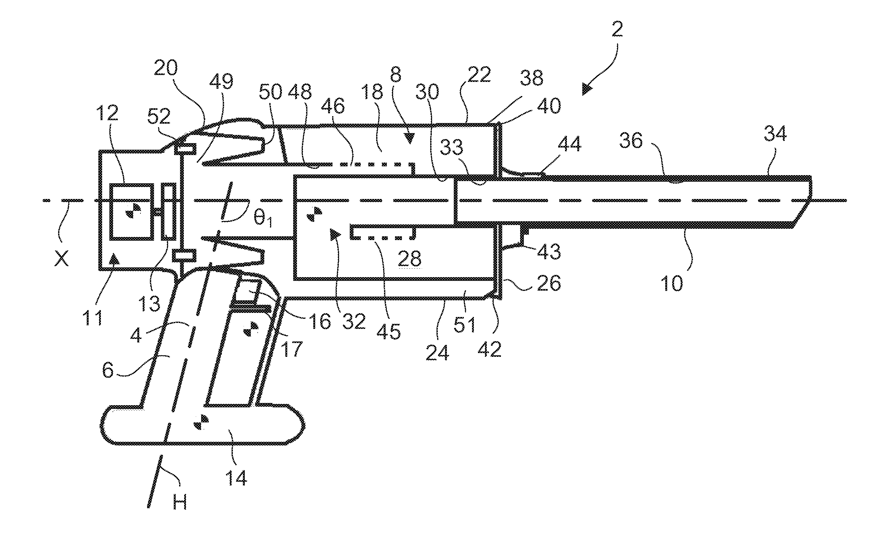
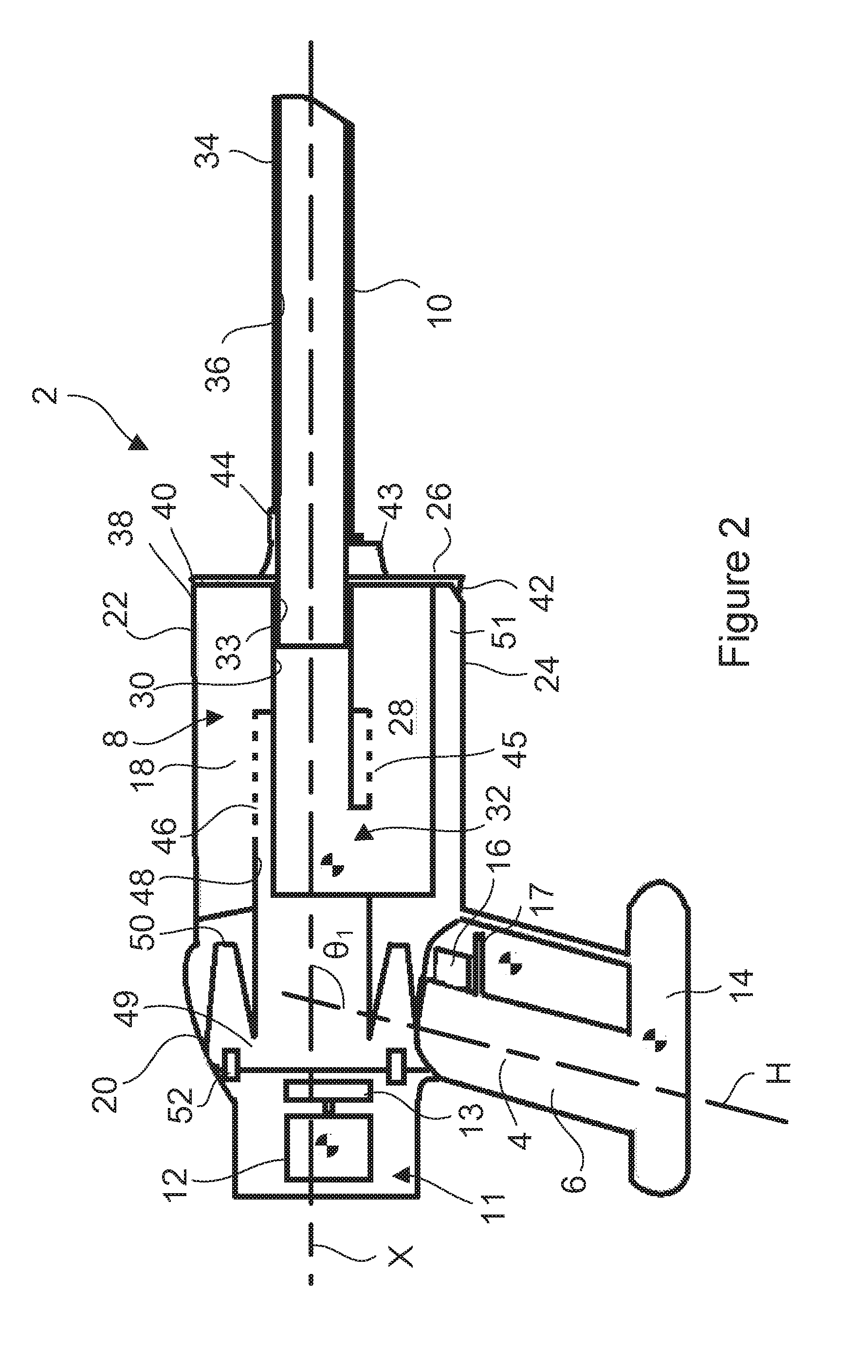
FIGS. 1 and 2 show a handheld vacuum cleaner 2 comprising a main body 4 having an elongate handle 6, a cyclonic separating unit 8 having a longitudinal axis X and a cleaning tool 10, in the form of a nozzle, which is secured to the cyclonic separating unit 8. The cyclonic separating unit 8 extends away from the handle 6 such that the cleaning tool 10 is at the end of the cyclonic separating unit 8 which is furthest from the handle 6. The cleaning tool 10 extends away from the cyclonic separating unit 8 along the longitudinal axis X of the cyclonic separating unit 8.
The main body 4 further comprises a suction generator 11 comprising a motor 12 and impeller 13 which are located above and towards the rear of the handle 6, and a battery 14 located directly below the handle 6. An actuator in the form of a finger-operated trigger 16 is provided at an upper portion of the handle 6. A trigger guard 17 extends forwardly from the handle below the trigger 16. The handle 6 is arranged at an angle .theta.1 with respect to the longitudinal axis X of the cyclonic separating unit 8 such that the handle 6 is in a pistol grip configuration. In the embodiment shown, a handle axis H is arranged at 110 degrees with respect to the longitudinal axis X of the cyclonic separating unit 8. The angle .theta.1 is the included angle between the longitudinal axis X extending forward of the handle 6 and the portion of the handle axis H extending through the handle 6.
The cyclonic separating unit 8 comprises a primary cyclonic separator 18 and a plurality of secondary cyclonic separators 20 positioned downstream of the primary cyclonic separator 18. The primary cyclonic separator 18 is adjacent a first end of the cyclonic separating unit 8 and the secondary cyclonic separators 20 are adjacent a second end of the cyclonic separating unit 8 which is opposite the first end. The secondary cyclonic separators 20 are arranged in a circular array which extend about the longitudinal axis X of the cyclonic separating unit 8.
The primary cyclonic separator 18 comprises a separator body 22 in the form of a bin having a cylindrical outer wall 24 and an end wall 26. The cylindrical outer wall 24 defines a cyclonic separation chamber 28. In the embodiment shown, it is the axis of the cyclonic separation chamber 28 which defines the longitudinal axis X of the cyclonic separating unit 8. A central duct 30 extends from the end wall 26 to an inlet 32 of the cyclonic separation chamber 28.
The cleaning tool 10 comprises a connector portion 33 and a nozzle portion 34 which define a duct 36 along the cleaning tool 10. The connector portion 33 has an outer diameter which is smaller than the inner diameter of the portion of the central duct 30 adjacent the end wall 26 such that the connector portion 33 can be inserted into the central duct 30 (as illustrated) thereby ensuring a rigid connection between the cleaning tool 10 and the cyclonic separating unit 8.
The central duct 30 and the duct 36 through the cleaning tool 10 together define an inlet duct 30, 36 which extends coaxially with the longitudinal axis X and through the end of the cyclonic separating unit 8 which is furthest from the handle 6. The inlet 32 of the cyclonic separation chamber 28 is spaced away from the end wall 26 and is located towards the end of the primary cyclonic separator 18 which is opposite the end of the cyclonic separating unit 8 to which the cleaning tool 10 is connected. The cyclonic separation chamber 28 therefore surrounds the portion of the inlet duct formed by the central duct 30. A first portion of the central duct 30 leading from the end wall 26 extends along the axis X of the cyclonic separation chamber 28. A second portion of the central duct 30 extends from the first portion to the inlet 32 of the cyclonic separation chamber 28. The second portion extends in a direction which has both radial and circumferential components with respect to the cyclonic separation chamber 28 so as to promote rotational flow within the cyclonic separation chamber 28 during use.
The end wall 26 and the portion of the cylindrical outer wall 24 adjacent the end wall 26 define a dirt collector 38, which is in the form of a dirt collecting bin, in which dirt separated from the incoming flow by the primary cyclonic separator 18 is collected.
The end wall 26 is connected to the cylindrical outer wall 24 by a pivot 40 and is held in a closed position by a user-operable catch 42. The end wall 26 can be moved from the closed position, in which dirt is retained within the dirt collector 38, to an open position, in which dirt can be removed from the dirt collector 38, by releasing the catch 42 and pivoting the end wall 26 away from the end of the cylindrical outer wall 24. The cleaning tool 10 is provided with retaining features (not shown) which engage with the central duct 30 so as to secure the cleaning tool 10 to the central duct 30. The cleaning tool 10 further comprises an annular collar 43 that abuts the end wall 26 thereby holding the end wall 26 in the closed position, and so prevents accidental opening of the end wall 26 while the cleaning tool 10 is attached. The cleaning tool 10 has a manually operated catch 44 that is actuated in order to disengage the retaining features from the central duct 24 in order to remove the tool 10 form the cyclonic separating unit 8.
A cylindrical shroud 45 is disposed centrally within the cyclonic separation chamber 28 and extends coaxially with the axis of the chamber 28. Apertures 46 provided through the shroud 45 define a fluid outlet from the cyclonic separation chamber 28.
A duct 48, which is formed in part by the shroud 45, provides fluid communication between the outlet from the cyclonic separation chamber formed by the apertures 46 and inlets 49 of the secondary cyclonic separators 20. Each secondary cyclonic separator 20 has a solids outlet 50 at one end which is in communication with a fine dust collector 51 that extends along the side of the primary cyclonic separator 18. A fluid outlet 52 at the end of each of the secondary cyclonic separators 20 opposite the solids outlet 50.
The cyclonic separating unit 8, suction generator 11 and battery 14 are expected to be the heaviest components of the vacuum cleaner 2. The separator 8 has a centre of gravity which is forward of the trigger guard 17 and so generates a clockwise moment about the trigger 16 and the trigger guard 17 (as viewed in FIG. 2). The battery 14 has a centre of gravity which is rearward of the trigger guard 17. The battery 14 therefore exerts an anticlockwise moment about the trigger 16 and the trigger guard 17. The suction generator 11 also has a centre of gravity which is rearward of the trigger guard 17. The cyclonic separating unit 8, suction generator 11 and battery 14 are positioned such that the net moment of all of the components of the vacuum cleaner 2 about an axis that extends perpendicularly with respect to the handle 6 and the longitudinal axis X of the cyclonic separating unit 8 and which passes through a region immediately below the trigger guard 17 is zero. The centre of gravity of the vacuum cleaner 2 is therefore located within the region below the trigger guard 17 such that when the trigger 16 is released by a user, the handheld vacuum cleaner 2 is balanced about a point below the trigger guard 17 and so can be supported easily by the rest of the user's fingers on the handle 6 and the upper finger against the trigger guard 17 without tipping forwards or backwards. Furthermore, the vacuum cleaner 2 can be supported on the battery 14, which forms a base of the vacuum cleaner 2, without toppling over.
FIG. 3 shows the vacuum cleaner 2 from the front. The cleaning tool 10 is relatively straight and slender and extends along the longitudinal axis X. The cleaning tool 10 therefore extends within the outer profile of the cyclonic separating unit 8 as viewed from the front of the vacuum cleaner 2 along the longitudinal axis X.
In use, the handheld vacuum cleaner 2 is activated by a user pressing the trigger 16 with an index finger. Dirty air is drawn by the suction generator 11 through the inlet duct 30, 36 and through the inlet 32 into the cyclonic separation chamber 28. The rotational flow promoted by the second portion of the central duct 30 within the cyclonic separation chamber 28 produces a cyclonic action that separates relatively heavy or large dirt from the air. Typically, the vacuum cleaner 2 is held such that the cyclonic separating unit 8 points downwardly from the handle 6. Dirt separated in the cyclonic separation chamber 28 therefore falls under the influence of gravity into the dirt collector 38. The partially cleaned air passes through the apertures 46 in the shroud 45 and is drawn along the duct 48 to the secondary cyclones 20. Smaller and lighter particles of dirt are separated from the air by the secondary cyclones 20 and expelled through the respective solids outlets into the fine dust collector 51. The cleaned air exits the secondary cyclones 20 via the respective fluid outlets 52 of the secondary cyclones 20 through the suction generator 11 and out of vents (not shown) at the rear of the main body 4.
The alignment of the axis X of the cyclonic separating unit 8 with the cleaning tool 10 makes the vacuum cleaner 2 compact and enables the end of the cyclonic separating unit 8 to be inserted into confined spaces during cleaning, as illustrated in FIG. 4. The vacuum cleaner 2 is therefore particularly suitable for cleaning places that are difficult to reach, such as gaps between items of furniture, walls and appliances. Furthermore, the cyclonic separating unit 8 can be rotated substantially within its own profile during cleaning. That is, the area swept by the cyclonic separating unit 8 (as viewed along the longitudinal axis X) as the cyclonic separating unit 8 is rotated about its longitudinal axis X, is not significantly greater than the actual area occupied by the cyclonic separating unit 8. A schematic illustration of the vacuum cleaner 2 with the handle in a vertical orientation is shown in FIG. 5b. FIGS. 5a and 5c show the vacuum cleaner 2 rotated through 45 degrees away from the orientation shown in FIG. 5b in each direction. The cyclonic separating unit 8 can therefore be rotated clockwise and anticlockwise within the confined space without colliding with surfaces of the confined space, and so can be manipulated easily in order to clean hard-to-reach surfaces.
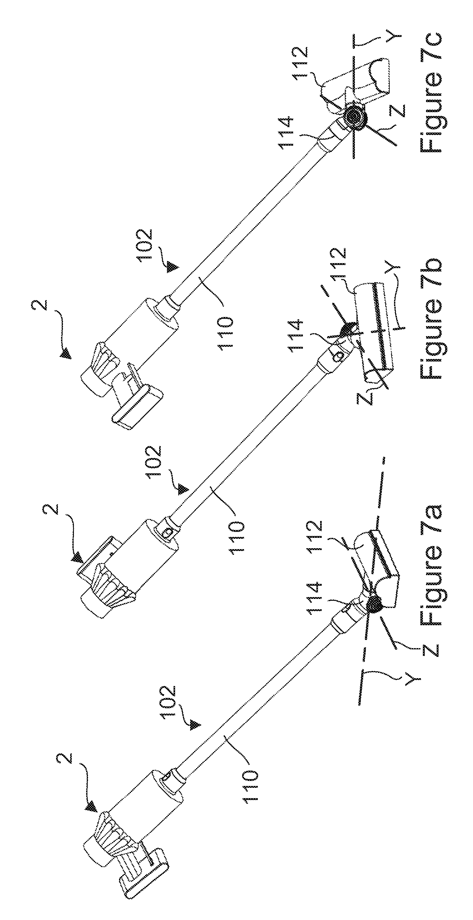
In addition to the above benefits, the alignment of the cleaning tool 10 with the longitudinal axis X ensures that the inclination angle of the cyclonic separating unit 8 does not vary as the vacuum cleaner 2 is rotated about the longitudinal axis X and so the separation of efficiencies of the primary cyclonic separator 18 and the secondary cyclonic separators 20 remain approximately constant during use. This is particularly advantageous when the cleaning tool 10 is replaced with a wand 110 and a cleaner head 112 to form a stick vacuum cleaner 102, as shown in FIG. 6.
The wand 110 extends coaxially with the longitudinal axis X of the cyclonic separating unit 8. The cleaner head 112 comprises an articulated neck 114 having first and second rotational axes Y, Z that are arranged perpendicular to each other. The arrangement of the axes Y, Z is such that, when the cleaner head 112 is placed on a surface with the wand 110 inclined with respect to the surface, rotation of the stick vacuum cleaner 102 about the longitudinal axis X of the cyclonic separating unit 8 (and hence rotation of the wand 110 about the wand axis) causes the cleaner head 112 to steer left or right, as shown in FIGS. 7a to 7c.
As mentioned above, the inclination of the longitudinal axis X of the cyclonic separating unit 8 remains substantially constant as the cleaner head 114 is steered across a surface being cleaned. Consequently, unlike known stick vacuum cleaners, the cyclonic separation efficiency remains substantially constant and the risk of re-entrainment remains low.
A further benefit is that the centre of gravity of the cyclonic separating unit 8 is located at or close to the axis of the wand 110. Consequently, the weight balance of the cyclonic separating unit 8 about the axis of the wand 110 remains approximately constant as the cyclonic separating unit 8 is rotated during cleaning. The vacuum cleaner 2 is therefore easy to manoeuvre.
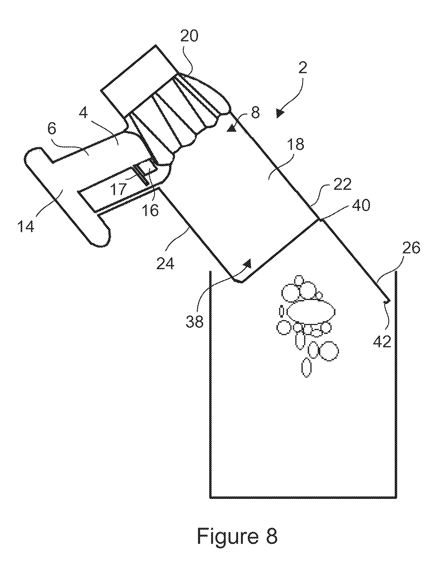
Referring to FIG. 8, in order to empty the dirt collector 38 and the fine dust collector 51 of either of the described embodiments, the user first disconnects the cleaning tool 10 or the wand 110. Then, whilst gripping the handle 6, the user points the vacuum cleaner 2 towards a suitable receptacle (e.g. a waste bin or bag) into which the dirt is to be emptied. The catch 42 is then released by the user and the end wall 26 pivoted from its closed position into its open position. Since the cyclonic separating unit 8 is pointed away from the user, there is no need for the user to adopt a different grip or posture from that which is adopted during normal cleaning. Consequently, the process by which the dirt collector 38 and the fine duct collector 51 are emptied is very intuitive and ergonomic. Furthermore, dirt exits the dirt collector 38/fine dust collector 51 from the end of the cyclonic separating unit 8 which is furthest from the handle 6. Therefore, there is less risk that dirt will spill from the dirt collector 38/fine dust collector 51 onto a user during emptying.
In an alternative arrangement, the inlet duct may be spaced from the axis of the cyclonic separating unit 8. Nevertheless, the cyclonic separating unit may be arranged to extend partly around a portion of the inlet duct or to entirely surround a portion of the inlet duct. For example, the inlet duct may be recessed into the side of the cyclonic separating unit such that duct extends within the profile of the cyclonic separating unit when viewed along the axis of the cyclonic separating unit.
* * * * *
D00000
D00001
D00002
D00003
D00004
D00005
D00006
D00007
D00008
XML
uspto.report is an independent third-party trademark research tool that is not affiliated, endorsed, or sponsored by the United States Patent and Trademark Office (USPTO) or any other governmental organization. The information provided by uspto.report is based on publicly available data at the time of writing and is intended for informational purposes only.
While we strive to provide accurate and up-to-date information, we do not guarantee the accuracy, completeness, reliability, or suitability of the information displayed on this site. The use of this site is at your own risk. Any reliance you place on such information is therefore strictly at your own risk.
All official trademark data, including owner information, should be verified by visiting the official USPTO website at www.uspto.gov. This site is not intended to replace professional legal advice and should not be used as a substitute for consulting with a legal professional who is knowledgeable about trademark law.