Support assembly
Mesa , et al. No
U.S. patent number 10,463,226 [Application Number 15/323,067] was granted by the patent office on 2019-11-05 for support assembly. This patent grant is currently assigned to ELECTROLUX APPLIANCES AKTIEBOLAG. The grantee listed for this patent is ELECTROLUX APPLIANCES AKTIEBOLAG. Invention is credited to Rickard Hederstierna, Daniel Mesa.


| United States Patent | 10,463,226 |
| Mesa , et al. | November 5, 2019 |
| **Please see images for: ( Certificate of Correction ) ** |
Support assembly
Abstract
A support assembly for supporting one or more objects in a dishwasher is provided. The support assembly may include a snap arrangement with snap fittings for snapping the snap arrangement onto a rack of the dishwasher. The support assembly may include a main frame having a first side and a second side, where the first side may be provided with a soft surface structure, and where the main frame may be foldably arranged to the snap arrangement to allow the main frame to be folded between at least a supporting position and a storing position. The soft surface structure of the first side may be arranged to support a portion of the one or more objects when the main frame is in the supporting position. The embodiments herein may also relate to a rack of a dishwasher and a dishwasher comprising a rack.
| Inventors: | Mesa; Daniel (Stockholm, SE), Hederstierna; Rickard (Stockholm, SE) | ||||||||||
|---|---|---|---|---|---|---|---|---|---|---|---|
| Applicant: |
|
||||||||||
| Assignee: | ELECTROLUX APPLIANCES
AKTIEBOLAG (Stockholm, SE) |
||||||||||
| Family ID: | 51429314 | ||||||||||
| Appl. No.: | 15/323,067 | ||||||||||
| Filed: | September 1, 2014 | ||||||||||
| PCT Filed: | September 01, 2014 | ||||||||||
| PCT No.: | PCT/EP2014/068529 | ||||||||||
| 371(c)(1),(2),(4) Date: | December 29, 2016 | ||||||||||
| PCT Pub. No.: | WO2016/034202 | ||||||||||
| PCT Pub. Date: | March 10, 2016 |
Prior Publication Data
| Document Identifier | Publication Date | |
|---|---|---|
| US 20180146837 A1 | May 31, 2018 | |
| Current U.S. Class: | 1/1 |
| Current CPC Class: | A47L 15/503 (20130101); A47L 15/505 (20130101); A47L 15/501 (20130101) |
| Current International Class: | A47L 15/50 (20060101) |
| Field of Search: | ;211/41.1-41.4,41.8,41.9,85.31,85.5,125,168,169,170,171,163,165,167 ;312/228.1 ;134/135 |
References Cited [Referenced By]
U.S. Patent Documents
| 572770 | December 1896 | Putnam |
| 1350351 | August 1920 | Abbott |
| 2142019 | December 1938 | Warner |
| 2144278 | January 1939 | Wallace |
| 2213918 | September 1940 | Lofstrand, Jr. |
| 2287611 | June 1942 | Harbison |
| 2708037 | May 1955 | Planeta |
| 3241516 | March 1966 | Hopkins |
| 3295696 | January 1967 | Cohen |
| 3433363 | March 1969 | Clearman |
| 3473756 | October 1969 | Jones |
| 3512227 | May 1970 | Krawagna |
| 3752322 | August 1973 | Fiocca et al. |
| 4029277 | June 1977 | Bulanda |
| 4406372 | September 1983 | Bell |
| 4437572 | March 1984 | Hoffman |
| 4589556 | May 1986 | Peretz |
| 4606464 | August 1986 | Jordan |
| 4909401 | March 1990 | McConnell |
| 5042418 | August 1991 | Hoover |
| 5048451 | September 1991 | Reimers |
| 5078281 | January 1992 | Johnson |
| 5103582 | April 1992 | Farmer |
| 5158185 | October 1992 | Michael |
| 5249590 | October 1993 | Jacobus |
| D342005 | December 1993 | Forsberg |
| 5287984 | February 1994 | Michael |
| 5277387 | November 1994 | Lewis et al. |
| 5363792 | November 1994 | Petechik |
| 5431294 | July 1995 | Stottmann |
| 5483916 | January 1996 | Kolvites |
| 5505318 | April 1996 | Goff |
| 5572776 | November 1996 | Murphy et al. |
| 5699631 | December 1997 | Tyson |
| 6109455 | August 2000 | Schroeder |
| 6123204 | September 2000 | Nelson et al. |
| 6386393 | May 2002 | Paulovich |
| 6394285 | May 2002 | Arthurs |
| 6546942 | April 2003 | Smith |
| D487825 | March 2004 | Kim |
| 6913233 | July 2005 | Puett, III |
| 6915757 | July 2005 | Urban |
| 6932312 | August 2005 | Chen |
| D509108 | September 2005 | Rosenberg |
| 7032604 | April 2006 | Welch |
| 7066105 | June 2006 | Tal |
| 7209345 | April 2007 | Jang |
| D547048 | July 2007 | Conway |
| 7458471 | December 2008 | Crudgington, Jr. |
| 7478642 | January 2009 | Koch |
| D586861 | February 2009 | Noble |
| 7523902 | April 2009 | Almeida |
| 7543712 | June 2009 | Purushothaman |
| 7556231 | July 2009 | Herbst et al. |
| 7644826 | January 2010 | Koch |
| 7931155 | April 2011 | Bastuji |
| D642039 | July 2011 | Forsberg |
| 7988107 | August 2011 | Miller et al. |
| 8522998 | September 2013 | Crookshanks |
| 8540085 | September 2013 | Klump |
| 8573576 | November 2013 | Clark |
| 8701898 | April 2014 | Chai |
| 8746467 | June 2014 | Jeong |
| 9326604 | May 2016 | Schuldt |
| D771476 | November 2016 | Prince |
| 9788673 | October 2017 | Gschwind, Jr. |
| 9877632 | January 2018 | Roberson |
| 2001/0000901 | May 2001 | Kambouris |
| 2003/0019998 | January 2003 | Kou |
| 2003/0084835 | May 2003 | Chao |
| 2004/0149668 | August 2004 | Fann |
| 2005/0109378 | May 2005 | Landsiedel |
| 2005/0236345 | October 2005 | Herbst |
| 2005/0242046 | November 2005 | Lee |
| 2005/0268945 | December 2005 | Hedstrom |
| 2006/0086307 | April 2006 | Kaz |
| 2006/0108298 | May 2006 | Kim |
| 2006/0113260 | June 2006 | Purushothaman |
| 2006/0138064 | June 2006 | Crudgington, Jr. |
| 2006/0169652 | August 2006 | Yang |
| 2006/0185698 | August 2006 | Adasch |
| 2006/0237042 | October 2006 | Weaver |
| 2006/0243681 | November 2006 | Bastuji |
| 2006/0254992 | November 2006 | Lim |
| 2006/0254993 | November 2006 | Lee |
| 2006/0254994 | November 2006 | Lim |
| 2006/0289038 | December 2006 | Hedstrom et al. |
| 2007/0039904 | February 2007 | Purushothaman |
| 2007/0131696 | June 2007 | Schessl |
| 2007/0137501 | June 2007 | Manuel |
| 2007/0163626 | July 2007 | Klein |
| 2007/0247039 | October 2007 | Anderson |
| 2008/0110480 | May 2008 | Choi |
| 2008/0116155 | May 2008 | Yang |
| 2008/0149149 | June 2008 | Ryu |
| 2008/0156750 | July 2008 | Richardson |
| 2008/0185352 | August 2008 | O'Hara |
| 2008/0302740 | December 2008 | Moser |
| 2009/0090681 | April 2009 | Graute |
| 2009/0120883 | May 2009 | Jadhav |
| 2009/0301977 | December 2009 | Amaral |
| 2010/0194254 | August 2010 | House |
| 2011/0001415 | January 2011 | Park |
| 2011/0011429 | January 2011 | Haltmayer |
| 2011/0025179 | February 2011 | Haltmayer |
| 2011/0192808 | August 2011 | Buhl |
| 2011/0233158 | September 2011 | Haider |
| 2011/0247990 | October 2011 | Chai |
| 2011/0253650 | October 2011 | Renz |
| 2011/0290804 | December 2011 | Kohles et al. |
| 2012/0031861 | February 2012 | Haltmayer |
| 2012/0056519 | March 2012 | Woo |
| 2012/0139400 | June 2012 | Hofpeter |
| 2012/0292270 | November 2012 | Klump |
| 2012/0292273 | November 2012 | McNamara |
| 2012/0306333 | December 2012 | Eng |
| 2013/0002107 | January 2013 | Paschini |
| 2013/0134115 | May 2013 | Hernandez-Ariguznaga |
| 2013/0299438 | November 2013 | McDaniel |
| 2013/0327366 | December 2013 | Godehardt |
| 2014/0021149 | January 2014 | Eng |
| 2014/0132136 | May 2014 | Kilic |
| 2014/0137906 | May 2014 | Shin |
| 2014/0285077 | September 2014 | Yoon |
| 2015/0033604 | February 2015 | Bigham |
| 2015/0053237 | February 2015 | Lee |
| 2015/0164301 | June 2015 | Bartloff |
| 2015/0182104 | July 2015 | Jeong |
| 2016/0037997 | February 2016 | Mesa |
| 2016/0096971 | April 2016 | Papke |
| 2017/0135553 | May 2017 | Mesa |
| 2017/0143166 | May 2017 | Kareesan |
| 2017/0258294 | September 2017 | Mesa |
| 2018/0035865 | February 2018 | Citak |
| 201061516 | May 2008 | CN | |||
| 101977539 | Feb 2011 | CN | |||
| 30 22 484 | Jan 1982 | DE | |||
| 92 16 330 | Apr 1994 | DE | |||
| 94 07 327 | Jul 1994 | DE | |||
| 94 21 847 | Nov 1996 | DE | |||
| 297 11 822 | Oct 1998 | DE | |||
| 297 20 069 | Mar 1999 | DE | |||
| 299 02 157 UI | May 1999 | DE | |||
| 298 22 086 | Jun 1999 | DE | |||
| 200 05 725 | Aug 2000 | DE | |||
| 102006012454 | Nov 2006 | DE | |||
| 1 356 761 | Oct 2003 | EP | |||
| 1 424 035 | Jun 2004 | EP | |||
| 1 683 465 | Jul 2006 | EP | |||
| 1 925 251 | May 2008 | EP | |||
| 1 929 928 | Jun 2008 | EP | |||
| 1929928 | Jun 2008 | EP | |||
| 2 245 975 | Nov 2010 | EP | |||
| 2 353 488 | Aug 2011 | EP | |||
| 2 554 099 | Feb 2013 | EP | |||
| 2 554 101 | Feb 2013 | EP | |||
| 2 777 475 | Sep 2014 | EP | |||
| 2152375 | Apr 1973 | FR | |||
| 1393054 | May 1975 | GB | |||
| 2321394 | Jul 1989 | GB | |||
| WO 2005/042212 | May 2005 | WO | |||
| WO 2007/057135 | May 2007 | WO | |||
| WO 2009/097139 | Aug 2009 | WO | |||
| WO 2013/045543 | Apr 2013 | WO | |||
| WO 2013/098009 | Jul 2013 | WO | |||
| WO 2014/094898 | Jun 2014 | WO | |||
| WO 2014/108079 | Jul 2014 | WO | |||
Other References
|
International Search Report and Written Opinion for Application No. PCT/EP2012/076769 dated Feb. 11, 2013. cited by applicant . Office Action for U.S. Appl. No. 14/654,980 dated Jul. 1, 2016. cited by applicant . Notice of Allowance for U.S. Appl. No. 14/654,980 dated Dec. 6, 2016. cited by applicant . Office Action for Chinese Application No. 201280078146.7 dated Oct. 10, 2016. cited by applicant . International Search Report and Written Opinion for Application No. PCT/EP2014/068527 dated Nov. 26, 2014. cited by applicant . International Search Report and Written Opinion for Application No. PCT/EP2014/068528 dated May 11, 2015. cited by applicant . International Search Report and Written Opinion for Application No. PCT/EP2014/068529 dated May 7, 2015. cited by applicant . Office Action for Chinese Application No. 201480080777.1 dated Jun. 29, 2018, 9 pages. cited by applicant . Office Action for Chinese Application No. 201480080777.1 dated Feb. 26, 2019, 12 pages. cited by applicant. |
Primary Examiner: Liu; Jonathan
Assistant Examiner: Barnett; Devin K
Attorney, Agent or Firm: Alston & Bird LLP
Claims
The invention claimed is:
1. A dishwasher rack assembly comprising: a dishwasher rack defining a rack bottom having a plurality of wires, and side walls which are generally perpendicular relative to the rack bottom; and a support assembly for supporting one or more objects in the dishwasher rack within a dishwasher, wherein said support assembly comprises: a pair of opposing side bars, wherein each side bar has a top surface, a bottom surface, a center, a distal end, and a proximal end, wherein the bottom surfaces each comprise snap fitting notches therein, wherein the snap fitting notches directly engage corresponding wires from said plurality of wires of the rack bottom to snap the support assembly onto the rack bottom, and a generally planar main frame having a first side, an opposing second side, a first end and an opposing second end, wherein said main frame is pivotably attached to said pair of opposing side bars at a location between each center and each distal end respectively along a single axis to connect the side bars to each other and to allow said main frame to pivot between at least a supporting position and a storing position while the snap fitting notches are engaged with the rack bottom, wherein the main frame only pivots relative to the pair of opposing side bars along said single axis; wherein, in the supporting position, the first side defines a top surface of the main frame and the second side defines a bottom surface of the main frame, wherein the bottom surface of the main frame is closer to the rack bottom than the top surface of the main frame, and said first side is configured to support said one or more objects thereon; and wherein, in the storing position, the first side defines the bottom surface of the main frame and the second side defines the top surface of the main frame, wherein the bottom surface of the main frame is closer to the rack bottom than the top surface of the main frame, and wherein said second side of the main frame is configured to support said one or more objects thereon, wherein an angle (a) between said supporting position and said storing position is approximately 180 degrees.
2. The dishwasher rack assembly according to claim 1, wherein said main frame is configured to be stored at said storing position to allow access to the rack bottom.
3. The dishwasher rack assembly according to claim 1, wherein said first side of the main frame is provided with a soft surface and said second side of the main frame defines a hard surface that is harder than the soft surface, wherein the soft surface comprises a set of protrusions at least partially covered by an elastic material.
4. The dishwasher rack assembly according to claim 1, further comprising a gripping unit frame configured to be attached to a corresponding side wall from said side walls of the dishwasher rack, wherein the gripping unit frame is spaced apart from the support assembly, wherein said gripping unit frame comprises one or more gripping units, wherein each gripping unit of said one or more gripping units is configured to grip a respective stemmed portion of one of said one or more objects while a respective rim portion of said one of said one or more objects rests on the main frame of the support assembly in the supporting position.
5. The dishwasher rack assembly according to claim 4, wherein said gripping unit frame is rotatable between at least a stored position and a gripping position.
6. The dishwasher rack assembly according to claim 4, wherein each gripping unit has a gripping mode and a releasing mode, wherein each gripping unit is configured to release each respective stemmed portion respectively in said releasing mode, and wherein each gripping unit is configured to grip each respective stemmed portion respectively in said gripping mode.
7. The dishwasher rack assembly according to claim 6, wherein each gripping unit comprises a first arm, a second arm, and a flexible strip arranged between said first and second arms.
8. The dishwasher rack assembly according to claim 7 wherein each flexible strip is configured to at least partially enclose each respective stemmed portion respectively when each gripping unit is in said gripping mode.
9. The dishwasher rack assembly according to claim 7, wherein said first arm and said second arm are configured to rotate with respect to the gripping unit frame, wherein a tip of a corresponding first arm and a tip of a corresponding second arm from a corresponding gripping unit from said one or more gripping units are configured to be closer to each other when said corresponding gripping unit from said one or more gripping units is in said gripping mode than in said releasing mode.
10. The dishwasher rack assembly according to claim 1, wherein, when in use, the dishwasher rack is a lower dishwasher rack of the dishwasher and the lower dishwasher rack includes one or more wheels.
11. The dishwasher rack assembly according to claim 1, wherein said dishwasher rack further comprises elongated tines configured to be rotatably attached to said dishwasher rack to allow said elongated tines to be rotated between at least an upright position and a collapsed position, wherein said elongated tines are configured to support items to be washed in said upright position, wherein, in said collapsed position, the elongated tines are configured to be generally parallel to the rack bottom, and wherein said elongated tines are configured to be urged toward said collapsed position by pivoting said main frame from said storing position to said supporting position.
12. A dishwasher comprising the dishwasher rack assembly according to claim 1.
13. The dishwasher rack assembly according to claim 1, wherein said first side is configured to rest on the rack bottom when the main frame is in the storing position.
14. The dishwasher rack assembly according to claim 1, wherein said second side is at least partially supported by a collapsed elongated tine when the main frame is in said supporting position.
15. The dishwasher rack assembly according to claim 1, wherein said main frame is configured to rest on different portions of the dishwasher rack in the respective supporting position and storing position while the pair of opposing side bars each remain in a same position.
16. The dishwasher rack assembly according to claim 1, wherein the single axis is defined off-center relative to a geometric center of the main frame, such that the main frame is configured to pivot between the supporting position and the storing position without moving the pair of opposing side bars.
17. The dishwasher rack assembly according to claim 1, wherein the pair of opposing side bars comprise a first bar configured to span at least two parallel wires from said plurality of wires of the rack bottom, wherein the snap fitting notches of the first bar comprise a first snap fitting notch and a second snap fitting notch, wherein the first snap fitting notch is configured to engage a first wire from said at least two parallel wires, where the second snap fitting notch is configured to engage a second wire from said at least two parallel wires, where the main frame is configured to pivot about the single axis parallel to the at least two parallel wires, and wherein the single axis is defined off-center relative to the first snap fitting notch and the second snap fitting notch.
18. The dishwasher rack assembly according to claim 17, wherein a second axis is defined between the first snap fitting notch and the second snap fitting notch, wherein a plurality of elongated tines, extending generally perpendicular to the at least two parallel wires and generally perpendicular relative to the second axis, are placed between the pair of opposing side bars without impinging the main frame in at least the storing position.
19. The dishwasher rack assembly according to claim 17, wherein the pair of side bars comprise a second bar, disposed parallel to the first bar, which is configured to span the at least two parallel wires of the rack bottom.
20. A rack assembly comprising: a dishwasher rack, wherein the dishwasher rack defines a rack bottom having a plurality of wires, and side walls which are generally perpendicular relative to the rack bottom; a support assembly for supporting one or more objects in the dishwasher rack, wherein the support assembly comprises: a snap arrangement comprising: a pair of opposing side bars comprising a first side bar and a second side bar, wherein each side bar has a top surface, a bottom surface, a center, a distal end, and a proximal end; wherein the bottom surface of the first side bar has a first snap fitting notch and a second snap fitting notch therein; and the bottom surface of the second bar has a third snap fitting notch and a fourth snap fitting notch therein, wherein the first snap fitting notch and the third snap fitting notch are each configured to simultaneously engage a first wire of at least two parallel wires from said plurality of wires of the rack bottom, wherein the second snap fitting notch and the fourth snap fitting notch are each configured to simultaneously engage a second wire of the at least two parallel wires from said plurality of wires of the rack bottom to secure the first bar and the second bar to the rack bottom, and a generally planar main frame defining a first side, an opposing second side, a first end, and an opposing second end, wherein the first side has a plurality of protrusions extending generally perpendicularly therefrom, wherein the first end of the main frame is pivotably attached to the distal end of each of the first and the second side bars respectively along a single axis to connect the first side bar and the second side bar together and allow the main frame to be pivoted between at least a supporting position and a storing position about the single axis while each snap fitting notch of the first side bar and the second side bar are engaged with the at least two parallel wires respectively, wherein the single axis is generally parallel to the at least two parallel wires, wherein the main frame only pivots relative to the pair of opposing side bars along said single axis; wherein, in the supporting position, a majority of the main frame is located in between the pair of opposing side bars, the first side defines a top surface of the main frame and the second side defines a bottom surface of the main frame, wherein the bottom surface of the main frame is closer to the rack bottom than the top surface of the main frame; and wherein, in the storing position, the first end of the main frame is located between the pair of opposing side bars and a majority of the main frame is not located in between the pair of opposing side bars, the first side defines the bottom surface of the main frame and the second side defines the top surface of the main frame, wherein the bottom surface of the main frame is closer to the rack bottom than the top surface of the main frame.
21. The support assembly according to claim 20, wherein the first snap fitting and the second snap fitting define a second axis extending therebetween, and wherein the second snap fitting is disposed between the first snap fitting and the single axis relative to an axial direction of the second axis, such that the support assembly is configured to receive a plurality of tines extending perpendicular to the at least two parallel wires and perpendicular to the second axis without impinging the main frame in at least the storing position with the plurality of tines being disposed between first snap fitting and the third snap fitting and between the second snap fitting and the fourth snap fitting respectively.
Description
TECHNICAL FIELD
The embodiments herein relates to a support assembly for supporting one or more objects in a dishwasher. The embodiments herein also relates to a rack of a dishwasher and a dishwasher comprising a rack.
BACKGROUND
Interior environments of today's dishwashers are not always adapted to receive delicate items such as wine glasses, champagne glasses etc. The interior of a dishwasher is usually designed to receive plates and it is desirably if the interior is robust enough to receive heavy and bulky cookware, such as pots and pans. Therefore, problems may arise when delicate items such as wine glasses, champagne glasses etc., are loaded into such an interior. An option is to dish such delicate items by hand, but dishwashing by hand is time consuming and many users also consider such activities to be burdensome.
Support assemblies have been provided which are intended to support items to be washed within a dishwasher. One such assembly is for example described in the document EP 2245975 A1. However, the support assemblies provided have not satisfactorily solved the above mentioned problems.
Therefore, in view of above, there is a need for an improved support assembly which may overcome some of the above mentioned problems.
SUMMARY
An object of the embodiments herein is to provide an improved support assembly.
According to an aspect of the embodiments herein, the object is achieved by a support assembly for supporting one or more objects in a dishwasher, where the support assembly comprises a snap arrangement, comprising snap fittings for snapping the snap arrangement onto a rack of the dishwasher, where the support assembly further comprises a main frame having a first side and a second side, where the first side is provided with a soft surface structure, and where the main frame is foldably arranged to the snap arrangement to allow the main frame to be folded between at least a supporting position and a storing position, where the soft surface structure of the first side is arranged to support a portion of the one or more objects when the main frame is in the supporting position. Since the soft surface structure of the first side is arranged to support a portion of the one or more objects when the main frame is in the supporting position, delicate items, such as glasses can be supported by the support assembly, without, or almost without, risk of breaking the delicate items. Thereby, an improved support assembly is provided.
Optionally, the main frame is arranged to be stored at the storing position to allow access to the rack. Thereby, a user may choose to use the first side, provided with the soft surface structure, to provide support to delicate items, such as glasses, or to fold the main frame to the storing position to thereby allow access to the rack such that it can accommodate other types of items to be washed, such as plates or cookware, such as pots and pans.
Optionally, the soft surface structure comprises a set of protrusions in an elastic material. In this manner, supporting of delicate items such as glasses may be further improved, since the set of protrusions may improve contacting, or grip, between the soft surface structure and the delicate items.
Optionally, an angle a between the supporting position and the storing position is approximately 180 degrees. In this manner, the soft surface structure of the first side may provide good support of the one or more objects when the main frame is in the supporting position, and at the same time, access may be allowed to the rack when the main frame is in the storing position.
Optionally, the support assembly further comprises a gripping unit frame, where the gripping unit frame comprises one or more gripping units where each gripping unit of the one or more gripping units is arranged to grip a respective stemmed portion of one of the one or more objects. In this manner, supporting of stemmed objects, such as wine glasses or champagne flutes, may be further improved. Thereby, such delicate items may also be better protected from damages caused by a user handling a rack of a dishwasher in a rough way.
Optionally, the gripping unit frame is foldable between at least a folded position and a gripping position. Thereby, a support assembly is provided where the gripping unit frame may be folded to a folded position when it is not in use to thereby provide space to other form of items to be washed than stemmed objects, and which may be folded to the gripping position when it is to be used to grip stemmed portions of stemmed objects. Thereby, a flexible support assembly is provided.
Optionally, each gripping unit has a gripping mode and a releasing mode where the each gripping unit is arranged to release the respective stemmed portion in the releasing mode, and where the each gripping unit is arranged to grip the respective stemmed portion in the gripping mode. Since each gripping unit has a gripping mode and a releasing mode, gripping of one or more stemmed objects may be ensured and removement of the one or more stemmed objects from the gripping unit frame may be facilitated.
Optionally, each gripping unit comprises a first arm and a second arm and a flexible strip arranged between the first and second arms. Since each gripping unit comprises a first arm and a second arm and a flexible strip arranged between the first and second arms, gripping of the one or more stemmed objects may be further improved.
Optionally, the flexible strip is arranged to at least partially enclose the stemmed portion of one of the one or more stemmed objects when the gripping unit is in the gripping mode. Since the flexible strip is arranged to at least partially enclose the stemmed portion when each gripping unit is in the gripping mode, gripping of the one or more stemmed objects may be further improved.
Optionally, the first arm and the second arm are rotatably arranged at the gripping unit frame and where a tip of the first arm and a tip of the second arm are arranged to be closer to each other when the gripping unit is in the gripping mode than in the releasing mode. Thereby, gripping of a stemmed portion of a stemmed object may be further improved.
Optionally, the support assembly is arranged to be snapped onto a lower rack of a dishwasher. Thereby, a support assembly is provided allowing delicate items such as wine glasses and champagne flutes to be accommodated in a lower rack of a dishwasher in a safe manner.
According to a second aspect of the embodiments herein, the object is achieved by a rack of a dishwasher comprising a support assembly according to some embodiments herein.
Optionally, the rack further comprises elongated tines foldably arranged to the rack to allow the elongated tines to be folded between at least an upright position and a folded position where the elongated tines are arranged to support items to be washed, such as plates, in the upright position, and where the folded position constitutes a position in which a main extension of the elongated tines are arranged to substantially coincide with an horizontal extension of the rack, where the tines are arranged to be in the folded position when the main frame is in the supporting position. Thereby, a rack is provided which can provide good support for items to be washed, such as plates, when the tines are in the upright position. At the same time the rack provide space for, and support for, delicate items such as wine glasses and champagne flutes when the tines are in the folded position and when the main frame is in the supporting position. As a result, a flexible rack is provided which is capable of accommodating both items to be washed, such as plates, and delicate items to be washed, such as wine glasses and champagne flutes, in a safe manner.
According to a third aspect of the embodiments herein, the object is achieved by a dishwasher comprising a rack according to some embodiments.
Further features of, and advantages with, the embodiments herein will become apparent when studying the appended claims and the following detailed description. Those skilled in the art will realize that the different features described may be combined to create embodiments other than those described in the following, without departing from the scope of the embodiments herein, as defined by the appended claims.
BRIEF DESCRIPTION OF THE DRAWINGS
The various aspects of the embodiments herein, including its particular features and advantages, will be readily understood from the following detailed description and the accompanying drawings, in which:
FIG. 1 illustrates a support assembly with a main frame in a supporting position,
FIG. 2 illustrates the support assembly illustrated in FIG. 1 with the main frame in a storing position,
FIG. 3 illustrates a rack of a dishwasher comprising a support assembly according to some embodiments,
FIG. 4 illustrates the rack of the dishwasher illustrated in FIG. 3 where a gripping unit frame is in a folded position,
FIG. 5 illustrates a gripping unit in a releasing mode, and
FIG. 6 illustrates the gripping unit illustrated in FIG. 5 in a gripping mode.
DETAILED DESCRIPTION
The embodiments herein will now be described more fully with reference to the accompanying drawings, in which example embodiments are shown. Disclosed features of example embodiments may be combined. Like numbers refer to like elements throughout.
Well-known functions or constructions will not necessarily be described in detail for brevity and/or clarity.
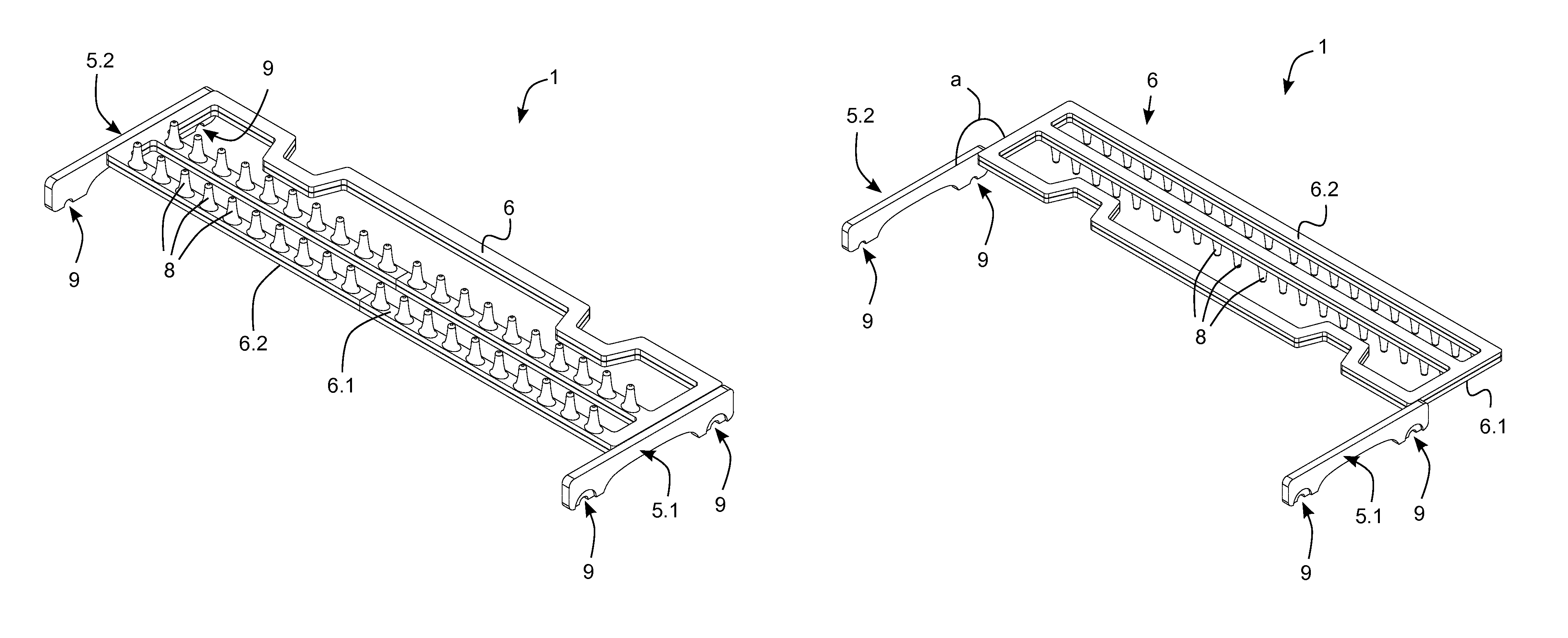
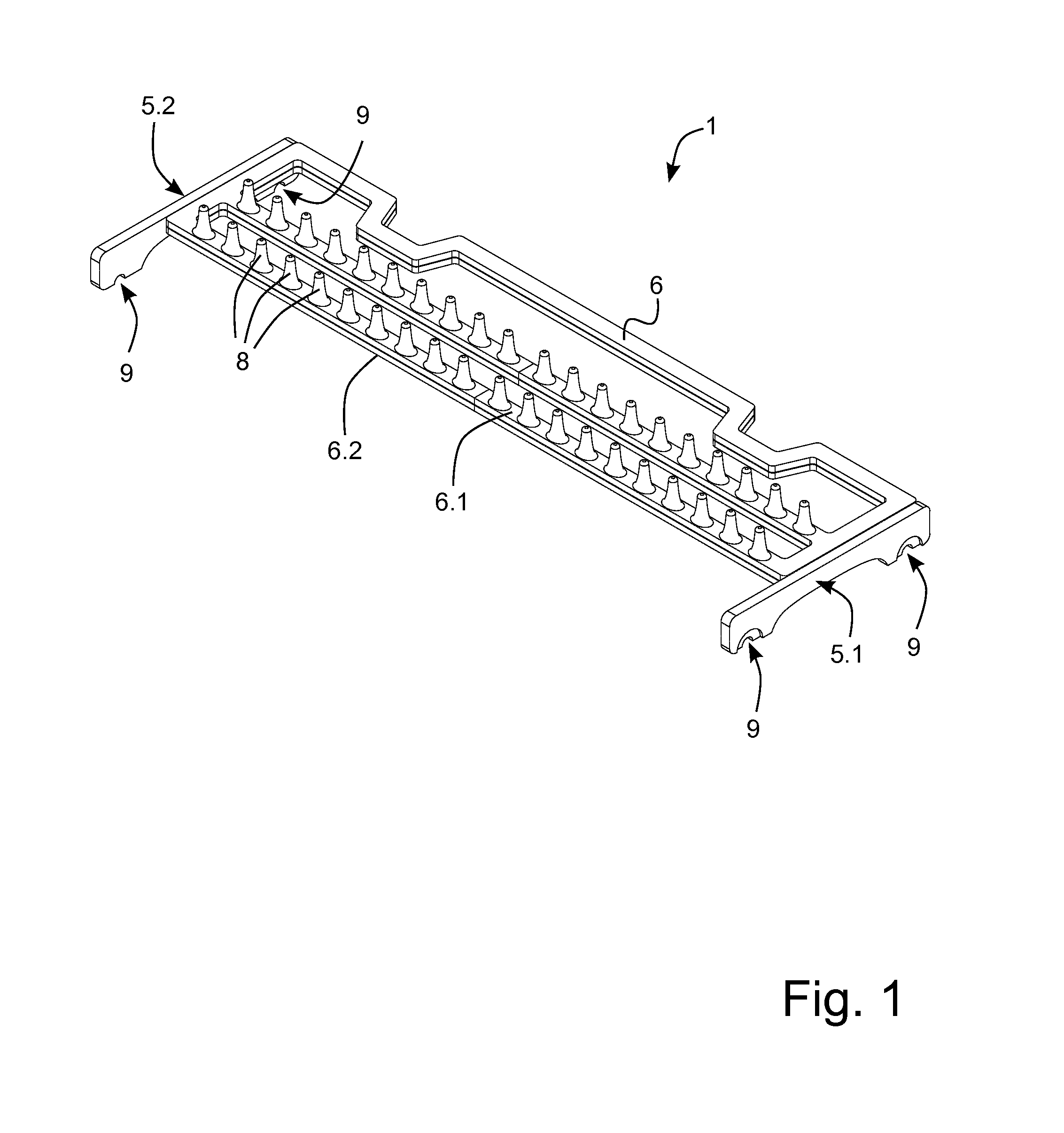
FIG. 1 illustrates a support assembly 1 for supporting one or more objects in a dishwasher. The support assembly 1 comprises a snap arrangement 5.1, 5.2 comprising snap fittings 9 for snapping the snap arrangement 5.1, 5.2 onto a rack of the dishwasher. The support assembly 1 further comprises a main frame 6 having a first side 6.1 and a second side 6.2, where the first side 6.1 is provided with a soft surface structure. The main frame 6 is foldably arranged to the snap arrangement 5.1, 5.2 to allow the main frame 6 to be folded between at least a supporting position and a storing position. The main frame 6 of the support assembly 1 illustrated in FIG. 1 is in the supporting position. As can be seen, the first side 6.1 which is provided with a soft surface structure is facing upwards in FIG. 1. The soft surface structure of the first side 6.1 is arranged to support a portion of the one or more objects when the main frame 6 is in the supporting position.
The soft surface structure comprises a set of protrusions 8 in an elastic material. The elastic material may be a ThermoPlastic Elastomers (TPE). Such elastic material may be moulded over Polypropylene (PP). In such embodiments, the ThermoPlastic Elastomers (TPE) may provide elasticity and the PolyPropylene (PP) may provide structure and rigidity. Due to these features, support may be further improved. In particular, support for delicate items, such as wine glasses or champagne flutes, may be improved.
The snap arrangement 5.1, 5.2 may comprise a first bar and a second bar, each comprising snap fittings 9 allowing them to be snapped onto a rack of a dishwasher. The snap fittings 9 may comprise semi-circular apertures having radiuses essentially corresponding to radiuses of wires of a rack onto which the support assembly 1 is arranged to be snapped. The snap arrangement 5.1, 5.2, as well as the main frame 6, may be provided in a plastic material such as Polypropylene (PP) or Polyoxymethylene (POM).
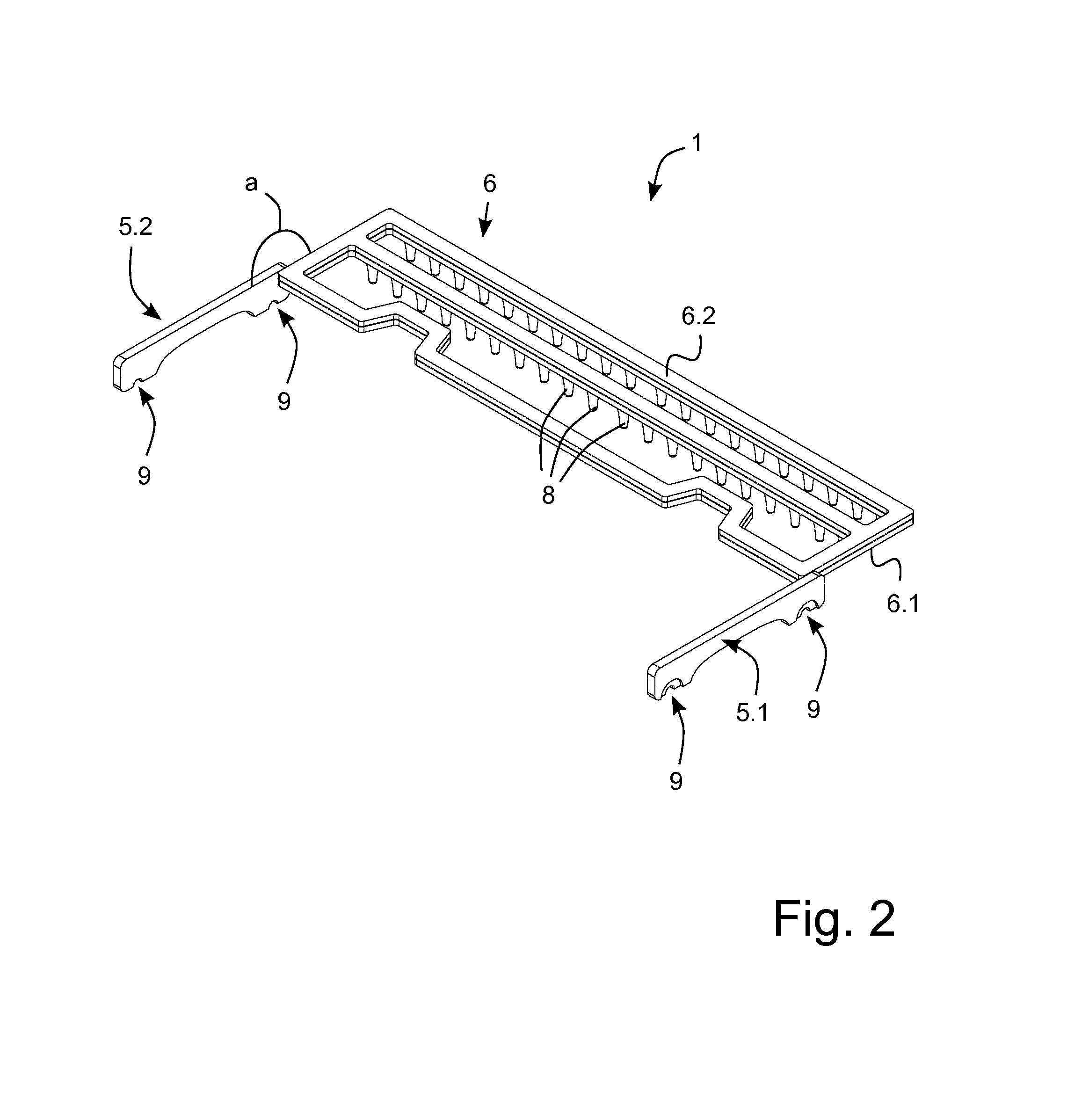
FIG. 2 illustrates the support assembly 1 illustrated in FIG. 1 with the main frame 6 in the storing position. As can be seen, the angle a between the supporting position and the storing position is approximately 180 degrees. Thereby, the first side 6.1, provided with the soft surface structure, faces upwards to thereby support a portion of the one or more objects when the mainframe 6 is in the supporting position, as illustrated in FIG. 1. Correspondingly, as illustrated in FIG. 2, the first side 6.1, provided with the soft surface structure, faces downwards to thereby protect the soft surface structure when the mainframe 6 is in the storing position. The second side 6.2 may be provided with a rigid surface structure and the second side 6.2 may be arranged to serve as a rigid floor for items to be washed when the main frame 6 is in the storing position.
Further, in embodiments where the soft surface structure comprises a set of protrusions 8 in an elastic material, these face upwards when the main frame 6 is in the supporting position and these face downwards when the main frame 6 is in the storing position. As a result, the support assembly 1 may provide good support for delicate items when the main frame 6 is in the supporting position and the support assembly 1 may provide access to the rack, and/or serve as a rigid floor for items to be washed, when the main frame 6 is in the storing position. Accordingly, a support assembly 1 is provided capable of providing support for both delicate items and heavy and bulky cookware such as pots and pans.
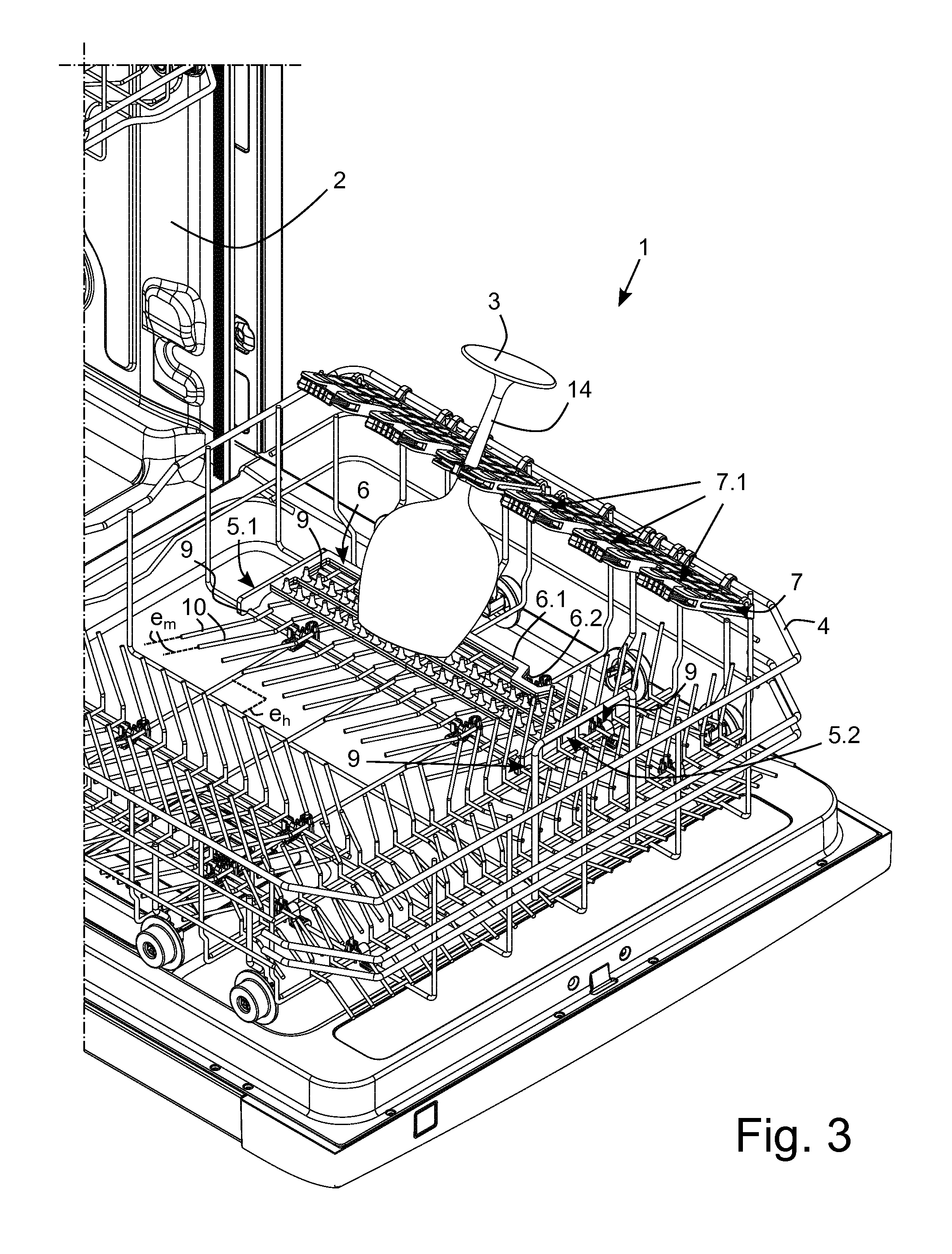
FIG. 3 illustrates a rack 4 of a dishwasher 2 comprising a support assembly 1 according to some embodiments. The support assembly 1 comprises a snap arrangement 5.1, 5.2 comprising snap fittings 9 for snapping the snap arrangement 5.1, 5.2 onto the rack 4 of the dishwasher 2. The support assembly 1 comprises a main frame 6 having a first side 6.1 and a second side 6.2. The main frame 6 of the support assembly 1 illustrated in FIG. 3 is in the supporting position. As can be seen, the soft surface structure of the first side 6.1 provides support for a portion of an object 3, in the form of a wine glass.
The support assembly 1 further comprises a gripping unit frame 7. The gripping unit frame 7 comprises one or more gripping units 7.1 where each gripping unit 7.1 of the one or more gripping units 7.1 is arranged to grip a respective stemmed portion 14 of one of the one or more objects 3. Thereby, good support for stemmed objects 3, such as wine glasses or champagne flutes, may be provided, even in cases where a user handles the rack 4 in a rough way, or careless way.
The rack 4 further comprises elongated tines 10 foldably arranged to the rack 4 to allow the elongated tines 10 to be folded between at least an upright position and a folded position. The elongated tines 10 are arranged to support dishes, such as plates, in the upright position. In FIG. 3, the tines 10 are illustrated in the folded position. As can be seen, the folded position constitutes a position in which a main extension e.sub.m of the elongated tines 10 are arranged to substantially coincide with an horizontal extension e.sub.h of the rack 4. The tines 10 are arranged to be in the folded position when the main frame 6 is in the supporting position. Thereby, space is provided for the main frame 6 such that the soft surface structure of the first side 6.1 of the main frame 6 may support portions the one or more objects 3.
The gripping unit frame 7 is foldable between at least a folded position and a gripping position. In FIG. 3, the gripping unit frame 7 is in the gripping position.
FIG. 4 illustrates the rack 4 of the dishwasher 2 illustrated in FIG. 3 where the gripping unit frame 7 is in the folded position. As illustrated, the gripping unit frame 7 may be tilted upwards to the folded position to thereby provide space for other form of items to be washed than stemmed objects within the rack 4. Also, as can be seen in FIG. 4, the tines 10 of the rack 4 has been folded to an upright position in FIG. 4 in comparison to the tines 10 illustrated in FIG. 3. Thereby, flat items to be washed, such as plates, can be accommodated in the rack 4 when the main frame 6 is in the storing position. Also, as illustrated in FIG. 4, the main frame 6 is arranged to be stored at said storing position to allow access to the rack 4 and the storing position constitutes a position in an outer portion of the rack 4.
As illustrated in FIG. 3 and FIG. 4, the support assembly 1 may be arranged to be snapped onto a lower rack 4 of a dishwasher 2. Thereby, also the lower rack 4 of the dishwasher 2 may be utilized to accommodate delicate items such as wine glasses or champagne glasses in a safe manner.
As illustrated in FIG. 3, each gripping unit 7.1 of the gripping unit frame 7 has a gripping mode and a releasing mode where the each gripping unit 7.1 is arranged to release the respective stemmed portion 14 in the releasing mode, and where the each gripping unit 7.1 is arranged to grip the respective stemmed portion 14 in the gripping mode.
FIG. 5 illustrates a gripping unit 7.1 in a releasing mode. The gripping unit 7.1 comprises a first arm 13.1 and a second arm 13.2 and a flexible strip 17 arranged between the first and second arms 13.1, 13.2. The first arm 13.1 and the second arm 13.2 are rotably arranged with respect to the gripping unit frame 7 of the holding assembly.
FIG. 6 illustrates the gripping unit illustrated in FIG. 5 in a gripping mode. As illustrated in FIG. 5, the flexible strip 17 is arranged to at least partially enclose a stemmed portion 14 of a stemmed object 3, when the gripping unit 7.1 is in the gripping mode.
Also, as can be seen in FIG. 5 and FIG. 6, a tip 15.1 of the first arm 13.1 and a tip 15.2 of the second arm 13.2 are arranged to be closer to each other when the gripping unit 7.1 is in the gripping mode than when the gripping unit is in the releasing mode.
The flexible strip 17 and/or the first arm 13.1 and the second arm 13.2 may be provided in a soft material. The soft material may be a ThermoPlastic Elastomer (TPE).
Due to these features, gripping of a stemmed portion 14 of a stemmed object 3 may be secured, even in cases where a user handles a rack in a rough way.
It is to be understood that the foregoing is illustrative of various example embodiments and the embodiments herein is not to be limited to the specific embodiments disclosed and that modifications to the disclosed embodiments, combinations of features of disclosed embodiments as well as other embodiments are intended to be included within the scope of the appended claims.
* * * * *
D00000
D00001
D00002
D00003
D00004
D00005
XML
uspto.report is an independent third-party trademark research tool that is not affiliated, endorsed, or sponsored by the United States Patent and Trademark Office (USPTO) or any other governmental organization. The information provided by uspto.report is based on publicly available data at the time of writing and is intended for informational purposes only.
While we strive to provide accurate and up-to-date information, we do not guarantee the accuracy, completeness, reliability, or suitability of the information displayed on this site. The use of this site is at your own risk. Any reliance you place on such information is therefore strictly at your own risk.
All official trademark data, including owner information, should be verified by visiting the official USPTO website at www.uspto.gov. This site is not intended to replace professional legal advice and should not be used as a substitute for consulting with a legal professional who is knowledgeable about trademark law.