Explosion protection circuit with impedance matching
Wiest , et al. Oc
U.S. patent number 10,461,526 [Application Number 15/506,794] was granted by the patent office on 2019-10-29 for explosion protection circuit with impedance matching. This patent grant is currently assigned to ENDRESS + HAUSER FLOWTEC AG. The grantee listed for this patent is Endress + Hauser Flowtec AG. Invention is credited to Andreas Berger, Oliver Brumberg, Achim Wiest.


| United States Patent | 10,461,526 |
| Wiest , et al. | October 29, 2019 |
Explosion protection circuit with impedance matching
Abstract
An apparatus for monitoring at least one physical or chemical process variable, comprising at least one sensor unit and an electronics unit for signal registration, evaluation and/or feeding, wherein the sensor unit is operated with alternating electrical current and/or communication between the electronics unit and the sensor unit occurs with alternating electrical current and/or alternating voltage. An explosion protection circuit with intrinsic safety, which includes a safety barrier, which has at least one unit for electrical current- and/or voltage limiting, is provided within the explosion protection circuit a unit for impedance matching, which unit for impedance matching includes at least one transformer.
| Inventors: | Wiest; Achim (Weil am Rhein, DE), Berger; Andreas (Hasel-Glashutten, DE), Brumberg; Oliver (Rheinfelden, DE) | ||||||||||
|---|---|---|---|---|---|---|---|---|---|---|---|
| Applicant: |
|
||||||||||
| Assignee: | ENDRESS + HAUSER FLOWTEC AG
(Reinach, CH) |
||||||||||
| Family ID: | 53887122 | ||||||||||
| Appl. No.: | 15/506,794 | ||||||||||
| Filed: | August 19, 2015 | ||||||||||
| PCT Filed: | August 19, 2015 | ||||||||||
| PCT No.: | PCT/EP2015/069044 | ||||||||||
| 371(c)(1),(2),(4) Date: | February 27, 2017 | ||||||||||
| PCT Pub. No.: | WO2016/030251 | ||||||||||
| PCT Pub. Date: | March 03, 2016 |
Prior Publication Data
| Document Identifier | Publication Date | |
|---|---|---|
| US 20170256937 A1 | Sep 7, 2017 | |
Foreign Application Priority Data
| Aug 29, 2014 [DE] | 10 2014 112 452 | |||
| Current U.S. Class: | 1/1 |
| Current CPC Class: | H01L 41/1132 (20130101); H02H 9/008 (20130101); H02H 9/02 (20130101); H04Q 9/00 (20130101); H03H 7/38 (20130101); H02H 9/045 (20130101); G08C 19/02 (20130101); H04Q 2209/886 (20130101); G01F 23/296 (20130101); G01F 1/66 (20130101) |
| Current International Class: | H02H 9/00 (20060101); H03H 7/38 (20060101); H02H 9/04 (20060101); H02H 9/02 (20060101); H04Q 9/00 (20060101); G08C 19/02 (20060101); H01L 41/113 (20060101); G01F 23/296 (20060101); G01F 1/66 (20060101) |
References Cited [Referenced By]
U.S. Patent Documents
| 3973170 | August 1976 | Hogan |
| 4708022 | November 1987 | Johnson |
| 5835534 | November 1998 | Kogure |
| 5907292 | May 1999 | Ahr |
| 6272922 | August 2001 | Stevens |
| 6397322 | May 2002 | Voss |
| 6885949 | April 2005 | Selli |
| 7791228 | September 2010 | Schaefer |
| 8736113 | May 2014 | Austerlitz |
| 9684322 | June 2017 | Cherewka |
| 2007/0090963 | April 2007 | Schaefer |
| 2011/0187182 | August 2011 | Austerlitz et al. |
| 2016/0072278 | March 2016 | Kollmer |
| 2538911 | Mar 1976 | DE | |||
| 19934876 | Feb 2000 | DE | |||
| 102014112452 | Mar 2016 | DE | |||
| 0817149 | Jan 1998 | EP | |||
Other References
|
English Translation of the International Preliminary Report on Patentability, WIPO, Geneva, CH--dated Mar. 9, 2017. cited by applicant . International Search Report, EPO, The Netherlands--dated Oct. 29, 2015. cited by applicant . German Search Report, German Patent Office, Munich, DE,--dated Apr. 29, 2015. cited by applicant. |
Primary Examiner: Kirkland, III; Freddie
Attorney, Agent or Firm: Bacon & Thomas, PLLC
Claims
The invention claimed is:
1. Field device for monitoring at least one physical or chemical process variable, comprising: at least one transformer; at least one sensor unit; an electronics unit for signal registration, evaluation and/or feeding; and an explosion protection circuit, wherein: said at least one sensor unit is operated with alternating electrical current and/or communication between said electronics unit and said at least one sensor unit occurs with alternating electrical current and/or alternating voltage; said explosion protection circuit with intrinsic safety, which includes a safety barrier, which has at least one unit for electrical current and voltage limiting, said explosion protection circuit is arranged fixedly between said at least one sensor unit and said electronics unit, and, there is provided within said explosion protection circuit a unit for impedance matching, which unit for impedance matching includes said at least one transformer; wherein said at least one sensor unit has at least one piezoelement, and wherein said unit for voltage limiting includes at least one coil, wherein said piezoelement with said unit for voltage limiting are shockproof against a mechanical impact with an energy of 7 Joule according to DIN EN60079-11.
2. The field device as claimed in claim 1, wherein: said unit for impedance matching is so embodied that said at least one sensor unit and said electronics unit are galvanically isolated from one another.
3. The field device as claimed in claim 2, wherein: said at least one transformer is so embodied, by assuring sufficiently large separations and suitable choice of materials, lacquers and insulating films, that the galvanic isolation is assured.
4. The field device as claimed in claim 1, wherein: said unit for electrical current limiting includes at least one resistor.
5. The field device as claimed in claim 1, wherein: equal components in the units for electrical current limiting, voltage limiting and impedance matching are designed in such a manner that they have a double function.
6. The field device as claimed in claim 1, wherein: said explosion protection circuit is arranged in a separate plug adapter, which plug adapter is retrofittably secured between said at least one sensor unit and said electronics unit.
7. The field device as claimed in claim 1, wherein: a number of parallel branches within said explosion protection circuit determines failure safety, where there is at least one single failure safety, when said explosion protection circuit has at least two parallel branches, and at least one double failure safety in the case of at least three parallel branches.
8. The field device as claimed in claim 1, wherein: at least one component, which is provided within the units for electrical current- and/or voltage limiting, is embodied multiple times.
9. The field device as claimed in claim 1, wherein: at least one of the components is designed failure safely.
10. The field device as claimed in claim 1, wherein: said explosion protection circuit includes a switch function, and, with said switch function, at least one unit for assuring intrinsic safety is shuntable.
11. The field device as claimed in claim 10, wherein: said switch function can be changed only with a special tool, especially with a key-operated switch, or said switch function is located in a region of the apparatus, which is accessible only by means of a special tool.
12. The field device as claimed in claim 1, wherein: regions of the apparatus, which are possibly exposed to an explosive atmosphere, are pottable and/or potted.
13. The field device as claimed in claim 1, wherein: between said explosion protection circuit and at least one additional component of the apparatus at least one connection is present, and each connection is releasable, or non-releasable, only by a tool.
Description
TECHNICAL FIELD
The invention relates to an apparatus for monitoring at least one physical or chemical process variable comprising at least one sensor unit and an electronics unit for signal registration, evaluation and/or feeding, wherein the apparatus is suitable for use in explosion-endangered regions.
BACKGROUND DISCUSSION
In order to operate a field device in an explosive atmosphere, various measures are necessary. These have the goal of preventing a spark formation, which, in given cases, could trigger an explosion, or avoiding that a spark occurring in the interior of a closed space has effects on the environment. In this regard, different protection regions are distinguished, and correspondingly there are different standards for different environmental conditions and applications. The standard DIN EN60079-11 defines the necessary safety requirements for device protection by intrinsic safety, known under the abbreviation Ex-i. This is an ignition protection type, which rests on the limiting of electrical energy within devices and/or connecting lines, which are exposed to a possibly explosive atmosphere, to a level below that at which an ignition can be brought about either by spark formation or by heat. Moreover, different protection levels are distinguished within this protection class, namely Ex-ia, Ex-ib and Ex-ic. These define the existing failure safety of the individual components and connecting lines.
For an explosion protection under class Ex-I, it must especially be assured that the electrical variables, electrical current, voltage and power, lie in a device at all times below respective, predetermined limit values. These limits values are so selected that, in the case of malfunction, e.g. because of a short circuit, the maximum occurring heat is not sufficient to produce an ignition spark. In this regard, the electrical current is frequently kept below its predetermined limit value by resistances, the voltage below its predetermined limit value by diodes, especially zener diodes, and the power below its predetermined limit value by a suitable combination of electrical current- and voltage limiting components. Such a protection circuit can be purchased, for example, under the designation MCR-PLUGTRAB PT from the firm, Phoenix Contact, as a pluggable apparatus. With reference to field devices, further, a number of examples are known, for example, in European Patent, EP0882955A1, German Patent, DE29809853U1 or published international application, WO2004/098014A1, in the case of which the requirements for explosion protection are fulfilled by particular circuit arrangements. WO2004/098014A1 describes arrangements of series resistors especially for the units for electrical current- and voltage limiting, while DE29809853U1 provides the application of Zener diodes. The application of diodes has, however, the disadvantage that the applications are limited to a certain temperature range.
Furthermore, the above mentioned examples of explosion protection circuits have no impedance matching. This concerns especially field devices, in the case of which the communication between electronics unit and sensor element occurs by means of alternating electrical current or alternating voltage. Typical frequencies lie in the range from 10 kHz to 50 MHz. The problem is that the load impedance of the sensor element is often not matched to the line, respectively electronics unit. This leads to standing waves on the line. Because of this, the complete power cannot be transmitted. Examples of such field devices include those where the sensor element drives or is driven by at least one piezoelement. These concern, among others, ultrasonic, flow measuring devices or vibronic, fill level measuring devices, such as sold by the applicant in great variety, in the first case under the designations, PROSONIC DDU10, PROSONIC Proline P, or PROSONIC Flow, and in the second case, under the designations, SOLIFANT and LIQUIFANT.
A typical method for assuring impedance matching, especially to a piezoelement, applies coils or transformers. The respective components must, based on their characteristics, be matched to the line, to the electronics unit, which has, in this case, usually an amplifier, and to the piezoelement.
SUMMARY OF THE INVENTION
An object of the present invention is to provide a field device with an explosion protection circuit, which enables operation of the field device in an explosive atmosphere coupled with simultaneous transmission of signals with minimal power loss.
The object is achieved according to the invention by an apparatus for monitoring at least one physical or chemical process variable, comprising at least one sensor unit and an electronics unit for signal registration, evaluation and/or feeding, wherein the sensor unit is operated with alternating electrical current and/or communication between the sensor unit and the electronics unit occurs with alternating electrical current and/or alternating voltage, and an explosion protection circuit with intrinsic safety, which includes a safety barrier, which has at least one unit for electrical current- and/or voltage limiting, wherein there is provided within the explosion protection circuit a unit for impedance matching, which unit for impedance matching includes at least one transformer. The impedance matching permits, in such case, an as loss free transmission of the signals as possible and correspondingly makes available more energy for the sensor unit, since a universal matching is possible over a large interval between the impedances of the sensor unit and the electronics unit.
In such case, it is advantageous, when the unit for impedance matching is so embodied that the sensor unit and the electronics unit are galvanically isolated from one another.
A corresponding embodiment of the transformer provides additionally for a zone isolation. This is especially advantageous for media contacting sensor units having a housing of metal and cathodic protection of a pipeline conveying the medium. The cathodic protection means in such an application that the potential of the pipeline relative to the ground connection is held by means of a voltage source at a certain value, especially, for example, U=5V, in order to prevent corrosion of the pipeline. Application of an explosion protection circuit with galvanic isolation between sensor unit and electronics unit enables, in this case, an independent operation of the circuits. This is often not the case for conventional explosion protection circuits.
For such purpose, it is advantageous, when the transformer is so embodied, especially by assuring sufficiently large separations and suitable choice of materials such as lacquers and insulating films, that the galvanic isolation is assured.
In a preferred embodiment, the unit for electrical current limiting includes at least one resistor. Equally advantageous is when the unit for voltage limiting includes at least one coil. Such a choice of the voltage limiting components permits application of the apparatus of the invention in a broad temperature range, especially the possible temperature range is greater than in the case of application of diodes.
In such case, it is, furthermore, advantageous, when respectively equal components in the units for electrical current limiting, voltage limiting and impedance matching are designed in such a manner that they have a double function. Thus, for example, the unit for voltage limiting and the unit for impedance matching can be combined via the transformer. Furthermore, the ohmic resistances of the windings of the coils can likewise act for electrical current limiting.
In another preferred embodiment, the sensor unit includes at least one piezoelement. This is especially the case in the application of the apparatus of the invention for ultrasonic, flow measuring devices or for vibronic, fill level measuring devices. The at least one process variable is then, for example, the flow of a medium through a pipe or the fill level of a medium in a container or the density or viscosity of the respective medium.
It is, furthermore, advantageous, when the explosion protection circuit is arranged fixedly between the sensor unit and the electronics unit. Alternatively, the explosion protection circuit can also be arranged in a separate plug adapter, which plug adapter is retrofittably secured between the sensor unit and electronics unit. In this case, already existing devices can be subsequently retrofitted with an explosion protection circuit and/or impedance matching.
In an especially preferred embodiment, the number of parallel branches determines the failure safety, especially there is at least one single failure safety, when the explosion protection circuit has at least two parallel branches, and there is at least one double failure safety in the case of at least three parallel branches. This corresponds to the standard Ex-ib. In the case of a double failure safety, which is achieved in the case of three parallel branches, even the standard Ex-ia is fulfilled.
In such case, it is advantageous, when at least one component, which is provided within the units for electrical current- and/or voltage limiting, is embodied multiple times. This relates especially to the case with two parallel branches within the explosion protection circuit, since the two branches are then embodied equivalently. In the case of a single failure safety, for example, two electrical current limiting resistances and two voltage limiting coils would be redundantly embodied, while in the case of a double failure safety, in each case, three coils and three resistances would be redundantly embodied.
Furthermore, it is advantageous when at least one of the components is designed failure safely. This can be achieved, for example, by coils having a wire gage of O>0.05 mm and a minimum failure voltage according to IEC of degree 2, by resistances, which are designed as wire resistances and which have a sufficient temperature resistance, and/or by conductive traces of corresponding cross section, especially height and width.
In another especially preferred embodiment, the explosion protection circuit includes a switch function. With this switch function, at least one unit for assuring intrinsic safety, especially the unit for electrical current limiting, can be shunted, especially short circuited. Thus, in the Not-Ex region, the transformer can be used without electrical current limiting, while in the Ex region a variant with electrical current limiting and zone isolation is provided.
In such case, it is especially advantageous, when the switch function can be changed only with a special tool, especially with a key-operated switch, or when it is located in a region of the apparatus, which is accessible only by means of a special tool.
It is advantageous, when the regions of the apparatus, which are possibly exposed to an explosive atmosphere, are pottable and/or potted.
It is, furthermore, advantageous, when between the explosion protection circuit and at least one additional component of the apparatus at least one connection is present, and when each connection is interruptible, or non-interruptible, only by tool.
BRIEF DESCRIPTION OF THE DRAWINGS
The invention will now be described in greater detail by means of the appended drawing based on a number of examples of embodiments. The figures of the drawing show as follows:
FIG. 1 is a block diagram of a field device according to the state of the art;
FIG. 2 is a circuit diagram of an explosion protection circuit of the invention with single failure safety;
FIG. 3 is a circuit diagram of an explosion protection circuit of the invention with a switch function of the invention; and
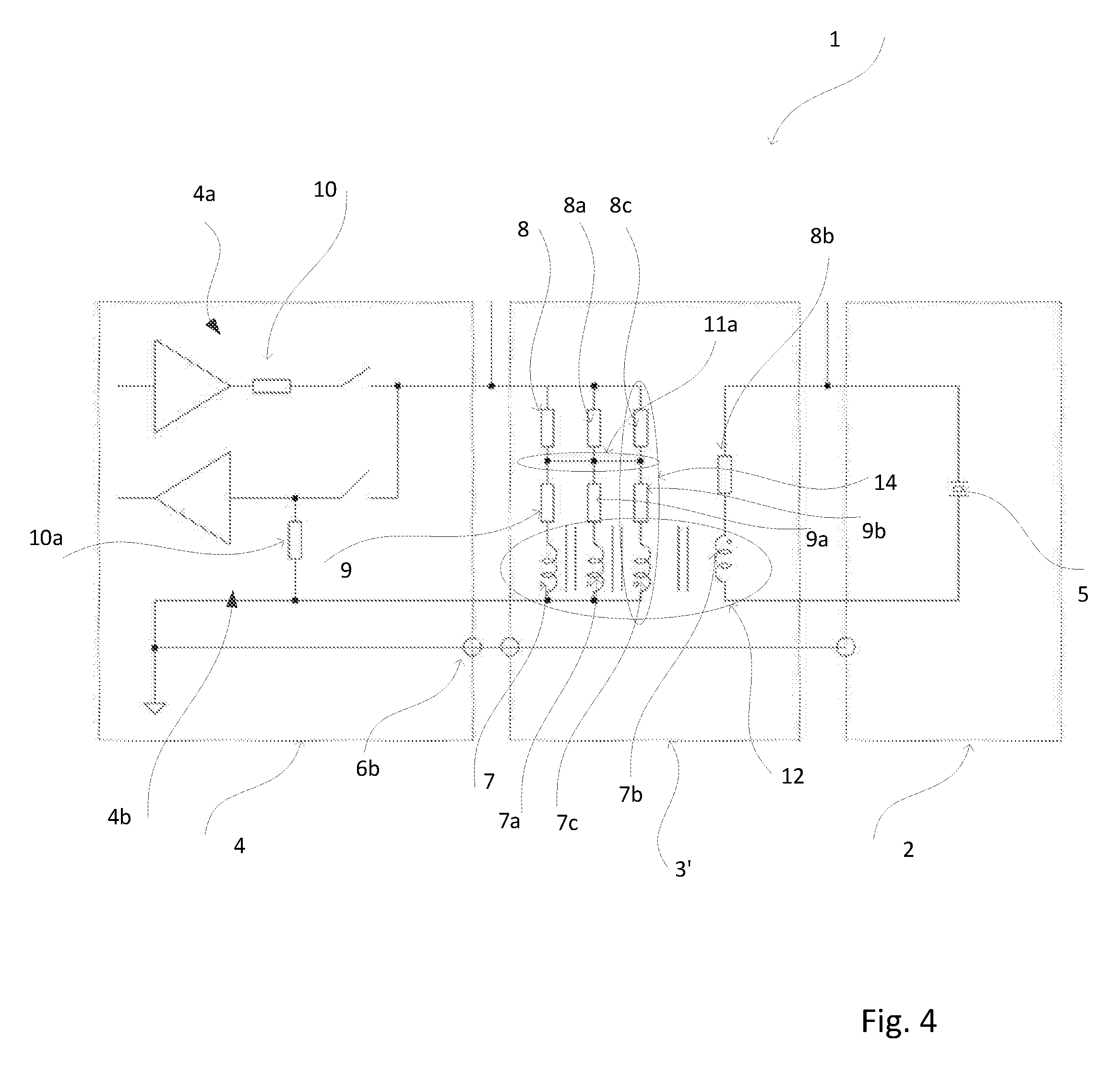
FIG. 4 is a circuit diagram of an explosion protection circuit of the invention with double failure safety.
DETAILED DISCUSSION IN CONJUNCTION WITH THE DRAWINGS
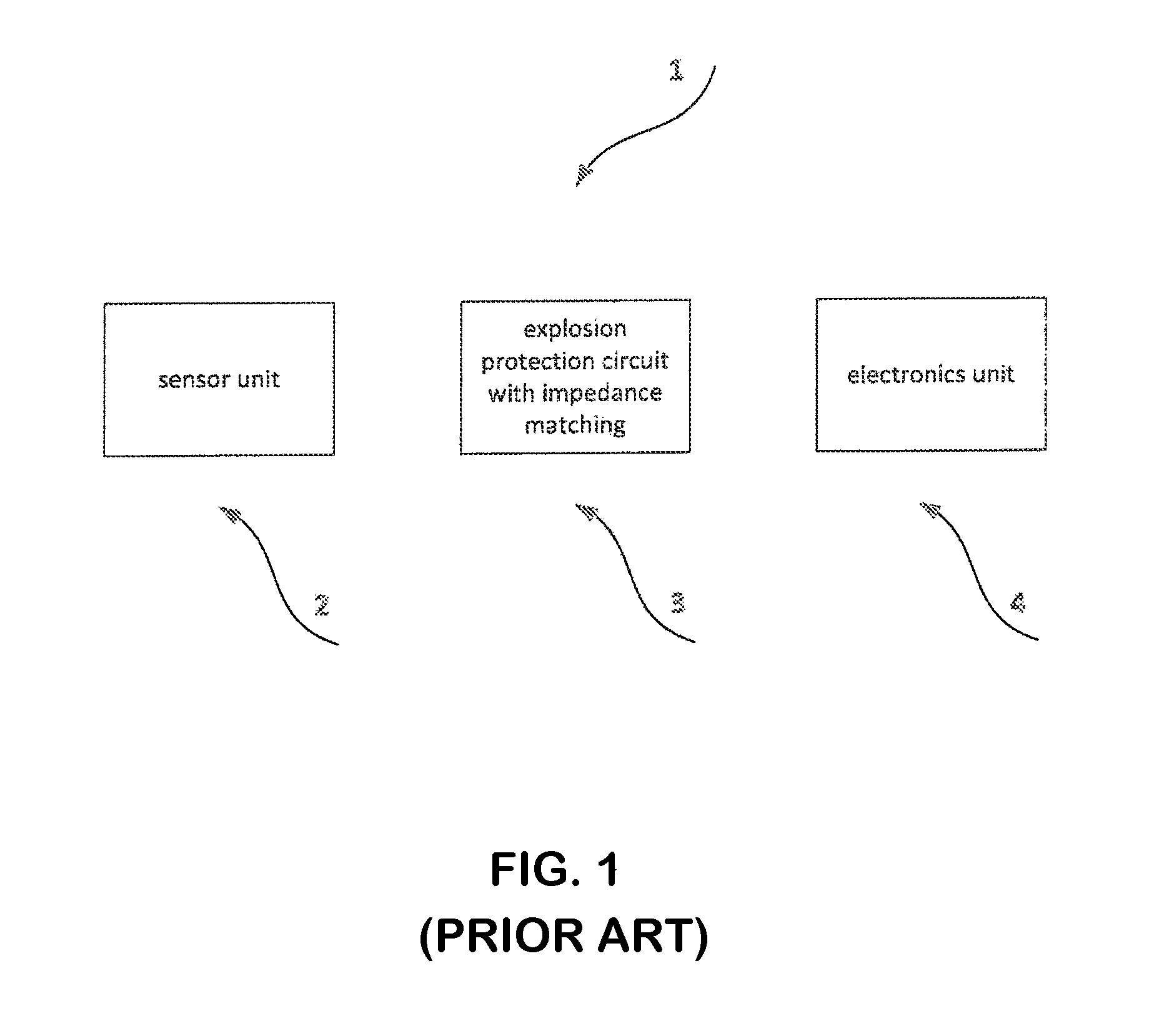
FIG. 1 shows a simplified block diagram of an apparatus 1 according to state of the art, such as, for example, a field device. The field device can be, for example, a flow measuring device working according to the ultrasonic principle. Such field devices are produced by the applicant in great variety and sold, for example, under the designation, Prosonic DDU10 or Prosonic Proline P. Other types of field devices also fall within the scope of the invention. As shown, apparatus 1 includes the sensor unit 2 and the electronics unit 4, between which is integrated an explosion protection circuit 3 of the invention. The explosion protection circuit 3 can be arranged fixedly, or provided in a separate plug adapter, which is placed releasably between the electronics unit 3 and the sensor unit 2.
Options for the explosion protection circuit include different variants, of which three different examples will be explained in detail below. Of course, many other arrangements can be provided, which also fall within the scope of the invention.
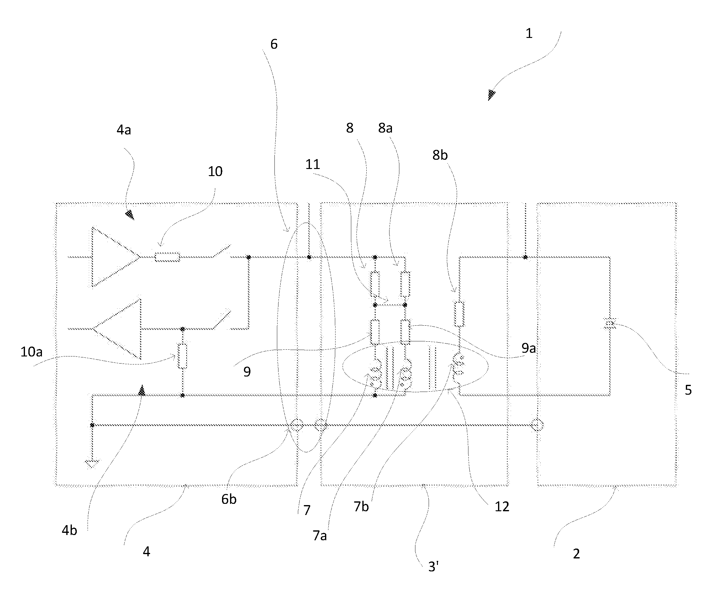
FIG. 2 shows a circuit diagram of an explosion protection circuit 3' of the invention having single failure safety and arranged between the electronics unit 4 and the sensor unit 2. Sensor unit 2 includes a piezoelement 5, which is located within a metal shielding and to which the impedance is matched. The signal carrying lines are provided by triaxial cable 6, of which one conductor 6b is connected with the respective metal housing. Used for impedance matching is a transformer 12 having at least three windings. As a rule, transformers are embodied with two windings. The third winding serves here correspondingly not for impedance matching, but, instead, for explosion protection. Thus, the transformer 12 in the illustrated example of an embodiment has a double function. Besides the at least one additional winding, it is advantageous, when the winding handedness on the side with the piezoelement 5 is opposite that on the side toward the electronics unit 4. This acts in the case of malfunction to reduce the stored energy.
The following descriptions refer exclusively to the explosion protection circuit 3'. The two circuit branches on the left side have each a coil 7,7a with each a line resistance 9,9a and each a series resistor 8,8a for electrical current limiting. This redundant construction provides a single failure safety of the explosion protection circuit 3'. In a third circuit branch on the side with the piezoelement 5 is another coil 7b and the associated line resistance 8b. By suitable choice of the inductances and mechanical embodiment of the coils 7,7a,7b, both the power can be suitably transformed, as well as also a zone isolation assured. The resistances 8,8a, in turn, serve for electrical current limiting. If one selects ohmic resistances, which are too low, then the electrical current is not sufficiently limited and the circuit assures only an impedance matching.
If the apparatus is operated in a non-explosion-endangered environment, such a choice of resistors 8,8a is advantageous, since more energy can be transmitted to the piezoelement 5. An explosion protection effect can only be achieved, when sufficiently high-valued ohmic resistances 8,8a are applied. It depends thus on the choice of the corresponding components and the desired application.
In the following, the explosion protective action of the circuit shown in FIG. 2 will be demonstrated based on a concrete example. In this regard, particular values are selected for the individual components and two energy considerations performed.
The inductive energy in a coil 7,7a,7b is given by
.times. ##EQU00001##
If one takes into consideration a standard safety factor of 1.5 for the electrical current, in the case of a coil 7b with L=1500 .mu.H and E.sub.ind=20 .mu.J (maximum allowed energy in the coil: E.sub.ind=40 .mu.J, taking into consideration a safety factor of 2) there results a maximum electrical current of
.times..times..times..mu..times..times..mu..times..times. ##EQU00002## and correspondingly for the resistor in the case of U=10V (DC in the case of malfunction)
.times..times..times..times..times..OMEGA. ##EQU00003##
Depending on choice of the series resistor 10 of the output stage 4a within the electronics unit 4, thus additional resistances 8,8a are necessary, in order to achieve a sufficient electrical current limiting. A typical value for the limiting resistor of the output stage 4a amounts to R.sub.10=50.OMEGA., so that the parallel circuit R.sub.s of the two resistances 8,8a would be selected at least high enough that R.sub.s=61.4.OMEGA.-50.OMEGA.=11.4.OMEGA..
Furthermore, a second resistor 10a is provided, the internal resistance of the input stage 4b. It is necessary for a reflection free transmission of the response signal. Typically selected for it is the same value that the limiting resistor 10 has. In the case of a matching of the alternating voltage during operation of the device, the sum of the impedances 7,7a,7b and resistances 8,8a should in the ideal case equal the value of R.sub.10a=R.sub.10, while R.sub.10, in turn, corresponds to the wave resistance of the triaxial cable 6. Likewise, at the working frequency, the phase of the protection circuit with connected piezoelement 5 should be .phi.=0.degree.. In the case of the resistors 8b,9 and 9a, these are the ohmic resistances of the windings.
A slight modification of the circuit of FIG. 2 is the provision of the connection 11. In this case, there results, due to the parallel circuit, R.sub.s=22.8.OMEGA.. Thus, the additional connection 11 provides an increase of the resistance R.sub.s and, thus, a reduction of the electrical current. On the other hand, when the connection 11 is omitted, less voltage drops on the resistors 8,8a, so that more energy is available to the piezoelement 5.
Somewhat the same holds for the so-called shock test for a mechanical impact with 7 J on the piezoelement 5. The energy without inductance should according to standard not exceed a value of 50 .mu.J.
In the Case of the Capacitive Energy
.times. ##EQU00004##
For a piezoelement with C=600 pF, a capacitive energy of E.sub.kap=20 .mu.J as well as taking into consideration a safety factor of 2.5 for the energy, there results for the voltage on the piezoelement
.times..times..times..mu..times..times..times..times. ##EQU00005##
The maximum voltage would, thus, in the case of a mechanical impact with 7 J, lie below U.sub.piezo=258V. By applying a coil 7b with L=1500 .mu.H on the side with the piezoelement as well as the other two coils 8,8a, this voltage is not achieved.
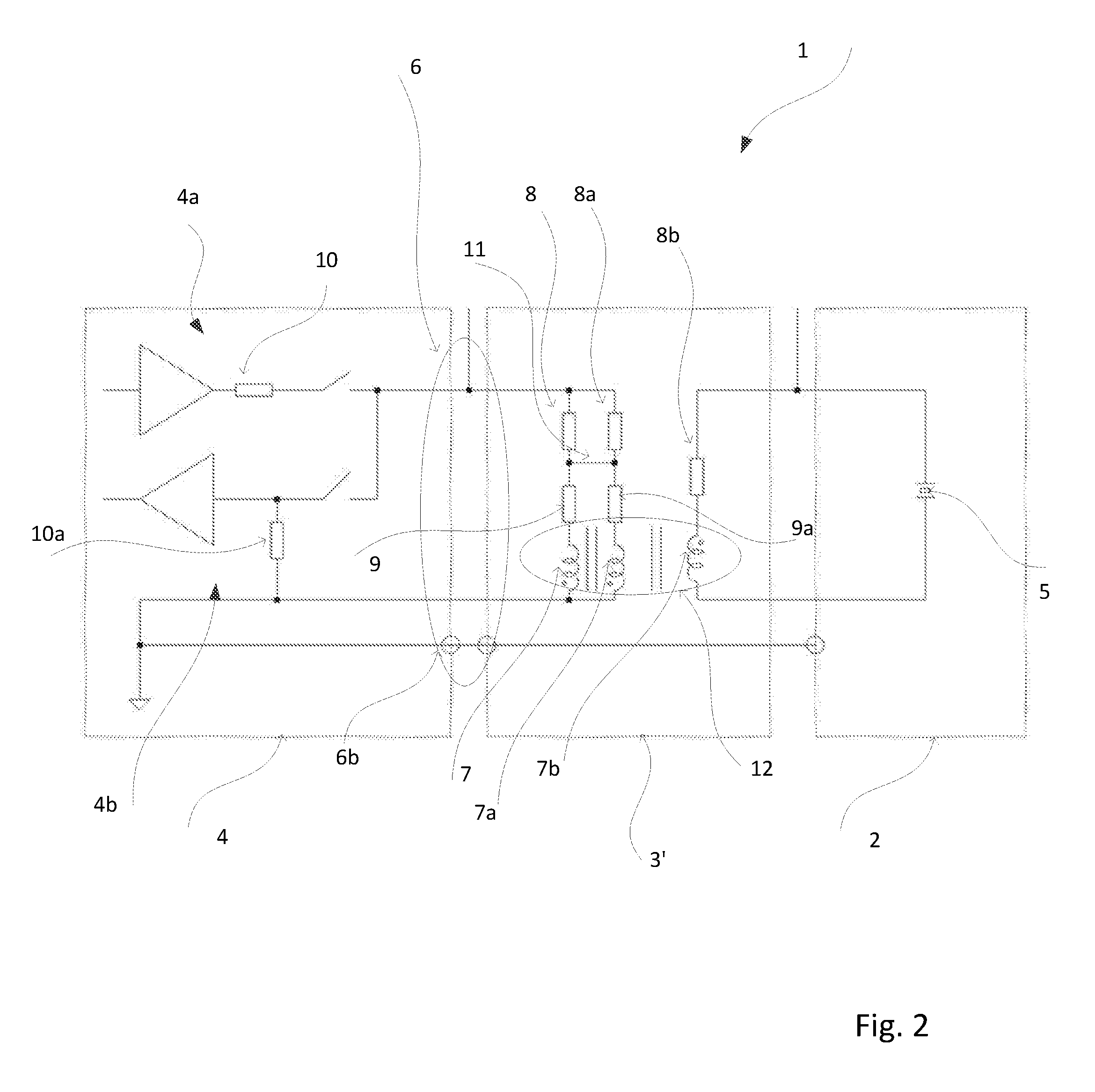
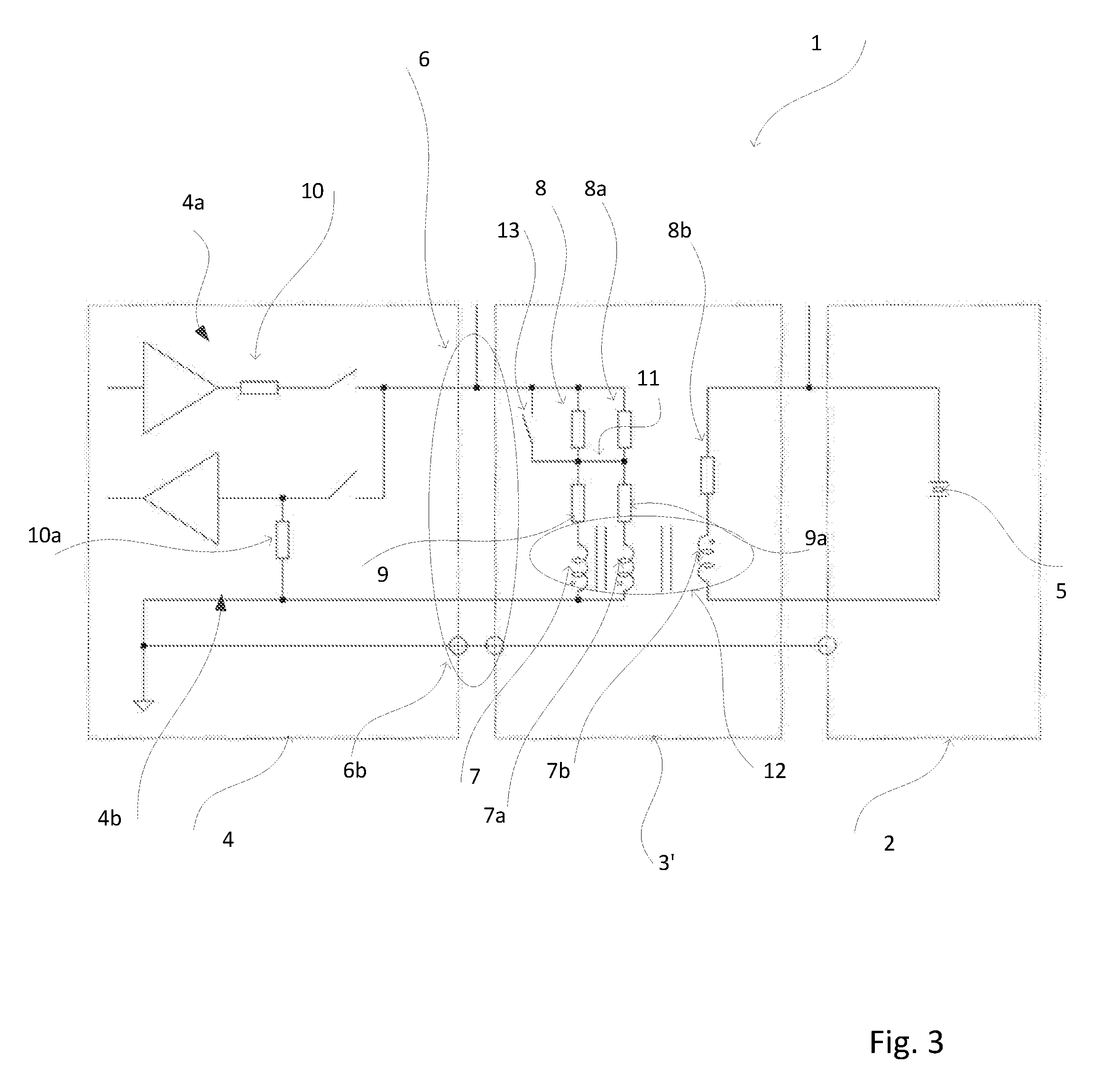
A second example of an explosion protection circuit 3'' is shown in FIG. 3. FIG. 3 differs from FIG. 2 only by the adding of a switch 13. This enables shunting of the resistances 8,8a connected in series with the coils 7,7a, so that the apparatus can be operated selectively with or without explosion protection action. This makes the deciding between high, respectively low, ohm resistors 8,8a unnecessary since, they can, at any time, be bypassed by means of the switch function.
A last example is shown in FIG. 4. In such case, of concern is an explosion protection circuit 3''' with double failure safety. This is achieved in the present example by a third circuit branch 14 on the side away from the piezoelement 5. In each of the circuit branches, a resistor 8,8a,8c is connected in series with a respective coil 7,7a,7c. Additionally, a connection 11a of the three circuit branches is added.
An alternative measure is to provide a sufficiently large separation between the circuit containing the piezoelement 5 and the circuit containing the three circuit branches. Then, higher voltages on the piezoelement can be used with little risk of a flashover during operation.
Of course, the essential functional units of the three illustrated examples are freely combinable with one another. This relates to the choice of the type of failure safety, the integration of additional switches, such as the switch function 13 in FIG. 3, and even the additional connection 11,11a. With reference to the individual components, the oscillatory circuits must then, however, be matched to the particular application.
In the case of a fixed arrangement of the explosion protection circuit, this can be arranged, for example, together with the circuit containing the piezoelement 5 in a potted housing. However, also other arrangements are, of course, implementable.
* * * * *
D00000
D00001
D00002
D00003
D00004
M00001
M00002
M00003
M00004
M00005
XML
uspto.report is an independent third-party trademark research tool that is not affiliated, endorsed, or sponsored by the United States Patent and Trademark Office (USPTO) or any other governmental organization. The information provided by uspto.report is based on publicly available data at the time of writing and is intended for informational purposes only.
While we strive to provide accurate and up-to-date information, we do not guarantee the accuracy, completeness, reliability, or suitability of the information displayed on this site. The use of this site is at your own risk. Any reliance you place on such information is therefore strictly at your own risk.
All official trademark data, including owner information, should be verified by visiting the official USPTO website at www.uspto.gov. This site is not intended to replace professional legal advice and should not be used as a substitute for consulting with a legal professional who is knowledgeable about trademark law.