Flexible containers with bottom support structure
Arent , et al. Oc
U.S. patent number 10,457,457 [Application Number 15/466,898] was granted by the patent office on 2019-10-29 for flexible containers with bottom support structure. This patent grant is currently assigned to The Procter & Gamble Company. The grantee listed for this patent is The Procter & Gamble Company. Invention is credited to Lee Mathew Arent, Kenneth Stephen McGuire, Jun You.


| United States Patent | 10,457,457 |
| Arent , et al. | October 29, 2019 |
Flexible containers with bottom support structure
Abstract
Flexible containers with structural support frames including bottom support structures.
| Inventors: | Arent; Lee Mathew (Fairfield, OH), You; Jun (West Chester, OH), McGuire; Kenneth Stephen (Montgomery, OH) | ||||||||||
|---|---|---|---|---|---|---|---|---|---|---|---|
| Applicant: |
|
||||||||||
| Assignee: | The Procter & Gamble
Company (Cincinnati, OH) |
||||||||||
| Family ID: | 58579271 | ||||||||||
| Appl. No.: | 15/466,898 | ||||||||||
| Filed: | March 23, 2017 |
Prior Publication Data
| Document Identifier | Publication Date | |
|---|---|---|
| US 20170305627 A1 | Oct 26, 2017 | |
Related U.S. Patent Documents
| Application Number | Filing Date | Patent Number | Issue Date | ||
|---|---|---|---|---|---|
| 62327625 | Apr 26, 2016 | ||||
| Current U.S. Class: | 1/1 |
| Current CPC Class: | B65D 35/10 (20130101); B65D 75/008 (20130101); B65D 75/5811 (20130101); B65D 85/70 (20130101) |
| Current International Class: | B65D 75/00 (20060101); B65D 75/58 (20060101); B65D 85/00 (20060101); B65D 35/10 (20060101) |
| Field of Search: | ;383/104,3,38,120 ;206/522 |
References Cited [Referenced By]
U.S. Patent Documents
| 3975885 | August 1976 | Carlisle |
| 4044867 | August 1977 | Fisher |
| 4858755 | August 1989 | Kuivanen |
| 4949530 | August 1990 | Pharo |
| 5137154 | August 1992 | Cohen |
| 5140801 | August 1992 | Wild |
| 5170609 | December 1992 | Bullock et al. |
| 5960975 | October 1999 | Lenartsson |
| 6244466 | June 2001 | Naslund |
| 6520491 | February 2003 | Timlick |
| 7207717 | July 2007 | Steele |
| 8181428 | May 2012 | Gustafsson |
| 8540094 | September 2013 | Riedl |
| 8661772 | March 2014 | Yasuhira |
| 8662751 | March 2014 | Forss |
| 8973756 | March 2015 | Liao |
| 9327867 | May 2016 | Stanley et al. |
| 9469088 | October 2016 | Stanley |
| 9586744 | March 2017 | Arent et al. |
| 9694942 | July 2017 | Stanley et al. |
| 9731889 | August 2017 | Stanley |
| 9802719 | October 2017 | Stanley |
| 9815258 | November 2017 | Stanley |
| 9896253 | February 2018 | You |
| 9914575 | March 2018 | You |
| 10005261 | June 2018 | Stanley |
| 10040581 | August 2018 | Stanley |
| 10131457 | November 2018 | Bourgeois |
| 10138049 | November 2018 | Cox |
| 2003/0094394 | May 2003 | Anderson et al. |
| 2004/0035865 | February 2004 | Rosen |
| 2005/0126941 | June 2005 | Ferri |
| 2006/0030471 | February 2006 | Schaller |
| 2007/0092164 | April 2007 | Yasuhira |
| 2007/0295633 | December 2007 | Liao |
| 2010/0308062 | December 2010 | Helou |
| 2012/0097634 | April 2012 | Riedl |
| 2013/0248540 | September 2013 | Darby |
| 2013/0292287 | November 2013 | Stanley et al. |
| 2013/0292353 | November 2013 | Stanley et al. |
| 2013/0292395 | November 2013 | Stanley et al. |
| 2013/0292413 | November 2013 | Stanley et al. |
| 2013/0292415 | November 2013 | Stanley et al. |
| 2013/0292431 | November 2013 | Stanley et al. |
| 2013/0294711 | November 2013 | Stanley et al. |
| 2013/0337244 | December 2013 | Stanley et al. |
| 2014/0033654 | February 2014 | Stanley et al. |
| 2014/0033655 | February 2014 | Stanley et al. |
| 2014/0250834 | September 2014 | Yoshikane et al. |
| 2015/0003758 | January 2015 | Warrington |
| 2015/0033671 | February 2015 | Stanley et al. |
| 2015/0034662 | February 2015 | Stanley |
| 2015/0034670 | February 2015 | Stanley et al. |
| 2015/0036950 | February 2015 | Stanley et al. |
| 2015/0121810 | May 2015 | Bourgeois et al. |
| 2015/0122373 | May 2015 | Bourgeois et al. |
| 2015/0122840 | May 2015 | Cox et al. |
| 2015/0122841 | May 2015 | McGuire et al. |
| 2015/0122842 | May 2015 | Berg, Jr. et al. |
| 2015/0122846 | May 2015 | Stanley et al. |
| 2015/0125099 | May 2015 | Ishihara et al. |
| 2015/0125574 | May 2015 | Arent et al. |
| 2015/0126349 | May 2015 | Ishihara et al. |
| 2016/0176578 | June 2016 | Stanley et al. |
| 2016/0176582 | June 2016 | McGuire et al. |
| 2016/0176583 | June 2016 | Ishihara et al. |
| 2016/0176584 | June 2016 | Ishihara et al. |
| 2016/0176597 | June 2016 | Ishihara et al. |
| 2016/0221727 | August 2016 | Stanley et al. |
| 2016/0297569 | October 2016 | Berg et al. |
| 2016/0297589 | October 2016 | You et al. |
| 2016/0297590 | October 2016 | You et al. |
| 2016/0297591 | October 2016 | You et al. |
| 2016/0325518 | November 2016 | Ishihara et al. |
| 2016/0362228 | December 2016 | McGuire et al. |
| 2017/0001782 | January 2017 | Arent et al. |
| 2017/0305609 | October 2017 | Mcguire et al. |
| 2018/0079574 | March 2018 | Ishihara et al. |
| 2018/0236741 | August 2018 | Hargett et al. |
| 2018/0237172 | August 2018 | Lester et al. |
| 2018/0257836 | September 2018 | Mcguire et al. |
| 2018/0297725 | October 2018 | Bourgeois et al. |
| 2018/0312283 | November 2018 | Bourgeois et al. |
| 2018/0312286 | November 2018 | Lester et al. |
| 1640777 | Jul 2005 | CN | |||
| 102005002301 | Jul 2006 | DE | |||
| 2631195 | Aug 2013 | EP | |||
| 07232744 | Sep 1995 | JP | |||
| H107159 | Jan 1998 | JP | |||
| 2005059924 | Mar 2005 | JP | |||
| 2005343492 | Dec 2005 | JP | |||
| 2006027697 | Feb 2006 | JP | |||
| 2006123931 | May 2006 | JP | |||
| 2006240651 | Sep 2006 | JP | |||
| 2009184690 | Aug 2009 | JP | |||
| 4639677 | Feb 2011 | JP | |||
| 2012025394 | Feb 2012 | JP | |||
| 2038815 | Jul 1995 | RU | |||
| WO 1996001775 | Jan 1996 | WO | |||
| WO 2005063589 | Jul 2005 | WO | |||
| WO 2008064508 | Jun 2008 | WO | |||
| WO 2012073004 | Jun 2012 | WO | |||
| WO 2013124201 | Aug 2013 | WO | |||
| WO2015051539 | Apr 2015 | WO | |||
Other References
|
Machine translation of the description of JP-2006123931-A. cited by examiner . "The Rigidified Standing Pouch--A Concept for Flexible Packaging", Phillip John Campbell, A Thesis Written in Partial Fulfillment of the Requirements for the Degree of Master of Industrial Design, North Carolina State University School of Design Raleigh, 1993, pp. 1-35. cited by applicant . All Office Actions, U.S. Appl. No. 13/888,721, filed May 7, 2013. cited by applicant . All Office Actions, U.S. Appl. No. 15/094,118, filed Apr. 8, 2016. cited by applicant . All Office Actions, U.S. Appl. No. 14/534,201, filed Nov. 6, 2014. cited by applicant . All Office Actions, U.S. Appl. No. 15/094,243, filed Apr. 8, 2016. cited by applicant . All Office Actions, U.S. Appl. No. 15/094,262, filed Apr. 8, 2016. cited by applicant . All Office Actions, U.S. Appl. No. 15/094,319, filed Apr. 8, 2016. cited by applicant . All Office Actions, U.S. Appl. No. 13/889,000, filed May 7, 2013. cited by applicant . U.S. Appl. No. 29/526,409, filed May 8, 2015, McGuire et al. cited by applicant . U.S. Appl. No. 15/094,118, filed Apr. 8, 2016, Stanley et al. cited by applicant . U.S. Appl. No. 15/466,898, filed Mar. 27, 2017, Arent et al. cited by applicant . U.S. Appl. No. 15/466,901, filed Mar. 27, 2017, McGuire et al. cited by applicant . International Search Report and Written Opinion dated May 29, 2017, 17 pgs. cited by applicant. |
Primary Examiner: Pascua; Jes F
Attorney, Agent or Firm: Weirich; David M
Claims
What is claimed is:
1. A disposable stand-up flexible container comprising: a product volume made from a flexible material; a plurality of structural support members, which supports the product volume, wherein each of the structural support members includes an expanded structural support volume made from a flexible material and expanded by an expansion material above atmospheric pressure, and wherein the plurality of structural support members includes: a front middle structural support member, oriented about vertically, and disposed on a front of the container and on a first side of the container, and extending from a top portion of the container through a middle portion of the container into a bottom portion of the container; a back middle structural support member, oriented about vertically, and disposed on a back of the container and on the first side of the container, and extending from a top portion of the container through a middle portion of the container into a bottom portion of the container; a bottom structural support member, oriented horizontally and substantially laterally, disposed on a front of the container and in a bottom portion of the container; a bottom middle structural support member, oriented horizontally and substantially perpendicular to the bottom structural support member, wherein an end of the bottom structural support member is joined to an end of the bottom middle structural support member; and wherein: at least part of the front middle structural support member is in contact with at least part of the back middle structural support member; and a lower portion of the front middle structural support member is spaced apart from a lower portion of the back middle structural support member by a reinforcing seal that is formed by sealed portions that are bounded by edges that are shared with the bottom portions of front middle structural support member and the back middle support member and a middle portion of a bottom middle structural support member, on at least the first side, such that each reinforcing seal has an overall shape that is a substantially triangular shape.
2. The container of claim 1, wherein 35-90% of an overall length of the front middle structural support member is in contact with at least 35-90% of an overall length of the back middle structural support member.
3. The container of claim 1, wherein 50-90% of an overall length of the front middle structural support member is in contact with 50-90% of an overall length of the back middle structural support member.
4. The container of claim 1, wherein: the lower portion of the front middle structural support member forms 15-50% of an overall length of the front middle structural support member; and the lower portion of the back middle structural support member forms 15-50% of an overall length of the back middle structural support member.
5. The container of claim 1, wherein: the lower portion of the front middle structural support member forms 25-50% of an overall length of the front middle structural support member; and the lower portion of the back middle structural support member forms 25-50% of an overall length of the back middle structural support member.
6. The container of claim 1, wherein the lower portion of the front middle structural support member is spaced apart from the lower portion of the back middle structural support member by a varying spaced apart distance that increases toward the bottom of the container.
7. The container of claim 6, wherein the lower portion of the front middle structural support member is spaced apart from the lower portion of the back middle structural support member by a largest spaced apart distance that is: larger than a largest cross-sectional dimension of the front middle structural support member at its lower end; and larger than a largest cross-sectional dimension of the back middle structural support member at its lower end.
8. The container of claim 6, wherein the lower portion of the front middle structural support member is spaced apart from the lower portion of the back middle structural support member by a largest spaced apart distance that is: larger than any cross-sectional dimension of the front middle structural support member; and larger than any cross-sectional dimension of the back middle structural support member.
9. The container of claim 6, wherein the lower portion of the front middle structural support member is spaced apart from the lower portion of the back middle structural support member by a largest spaced apart distance that is 0.5-10.0 centimeters.
10. The container of claim 6, wherein the lower portion of the front middle structural support member is spaced apart from the lower portion of the back middle structural support member by a largest spaced apart distance that is 1.0-5.0 centimeters.
11. The container of claim 1, wherein, in a lower half of the container, the front middle structural support member is symmetrical with the back middle structural support member with respect to a plane that separates the container into a front half and a back half.
Description
FIELD
The present disclosure relates in general to flexible containers, and in particular, to flexible containers having a bottom support structure.
BACKGROUND
Fluent products include liquid products and/or pourable solid products. In various embodiments, a container can be used to receive, contain, and dispense one or more fluent products. And, in various embodiments, a container can be used to receive, contain, and/or dispense individual articles or separately packaged portions of a product. A container can include one or more product spaces. A product space can be configured to be filled with one or more fluent products. A container receives a fluent product when its product space is filled. Once filled to a desired volume, a container can be configured to contain the fluent product in its product space, until the fluent product is dispensed. A container contains a fluent product by providing a barrier around the fluent product. The barrier prevents the fluent product from escaping the product space. The barrier can also protect the fluent product from the environment outside of the container. A filled product space is typically closed off by a cap or a seal. A container can be configured to dispense one or more fluent products contained in its product space(s). Once dispensed, an end user can consume, apply, or otherwise use the fluent product(s), as appropriate. In various embodiments, a container may be configured to be refilled and reused or a container may be configured to be disposed of after a single fill or even after a single use. A container should be configured with sufficient structural integrity, such that it can receive, contain, and dispense its fluent product(s), as intended, without failure.
A container for fluent product(s) can be handled, displayed for sale, and put into use. A container can be handled in many different ways as it is made, filled, decorated, packaged, shipped, and unpacked. A container can experience a wide range of external forces and environmental conditions as it is handled by machines and people, moved by equipment and vehicles, and contacted by other containers and various packaging materials. A container for fluent product(s) should be configured with sufficient structural integrity, such that it can be handled in any of these ways, or in any other way known in the art, as intended, without failure.
A container can also be displayed for sale in many different ways as it is offered for purchase. A container can be offered for sale as an individual article of commerce or packaged with one or more other containers or products, which together form an article of commerce. A container can be offered for sale as a primary package with or without a secondary package. A container can be decorated to display characters, graphics, branding, and/or other visual elements when the container is displayed for sale. A container can be configured to be displayed for sale while laying down or standing up on a store shelf, while presented in a merchandising display, while hanging on a display hanger, or while loaded into a display rack or a vending machine. A container for fluent product(s) should be configured with a structure that allows it to be displayed in any of these ways, or in any other way known in the art, as intended, without failure.
A container can also be put into use in many different ways, by its end user. A container can be configured to be held and/or gripped by an end user, so a container should be appropriately sized and shaped for human hands; and for this purpose, a container can include useful structural features such as a handle and/or a gripping surface. A container can be stored while laying down or standing up on a support surface, while hanging on or from a projection such as a hook or a clip, or while supported by a product holder, or (for refillable or rechargeable containers) positioned in a refilling or recharging station. A container can be configured to dispense fluent product(s) while in any of these storage positions or while being held by the user. A container can be configured to dispense fluent product(s) through the use of gravity, and/or pressure, and/or a dispensing mechanism, such as a pump, or a straw, or through the use of other kinds of dispensers known in the art. Some containers can be configured to be filled and/or refilled by a seller (e.g. a merchant or retailer) or by an end user. A container for fluent product(s) should be configured with a structure that allows it to be put to use in any of these ways, or in any other way known in the art, as intended, without failure. A container can also be configured to be disposed of by the end user, as waste and/or recyclable material, in various ways.
One conventional type of container for fluent products is a rigid container made from solid material(s). Examples of conventional rigid containers include molded plastic bottles, glass jars, metal cans, cardboard boxes, etc. These conventional rigid containers are well-known and generally useful; however their designs do present several notable difficulties.
First, some conventional rigid containers for fluent products can be expensive to make. Some rigid containers are made by a process shaping one or more solid materials. Other rigid containers are made with a phase change process, where container materials are heated (to soften/melt), then shaped, then cooled (to harden/solidify). Both kinds of making are energy intensive processes, which can require complex equipment.
Second, some conventional rigid containers for fluent products can require significant amounts of material. Rigid containers that are designed to stand up on a support surface require solid walls that are thick enough to support the containers when they are filled. This can require significant amounts of material, which adds to the cost of the containers and can contribute to difficulties with their disposal.
Third, some conventional rigid containers for fluent products can be difficult to decorate. The sizes, shapes, (e.g. curved surfaces) and/or materials of some rigid containers, make it difficult to print directly on their outside surfaces. Labeling requires additional materials and processing, and limits the size and shape of the decoration. Overwrapping provides larger decoration areas, but also requires additional materials and processing, often at significant expense.
Fourth, some conventional rigid containers for fluent products can be prone to certain kinds of damage. If a rigid container is pushed against a rough surface, then the container can become scuffed, which may obscure printing on the container. If a rigid container is pressed against a hard object, then the container can become dented, which may look unsightly. And if a rigid container is dropped, then the container can rupture, which may cause its fluent product to be lost.
Fifth, some fluent products in conventional rigid containers can be difficult to dispense. When an end user squeezes a rigid container to dispense its fluent product, the end user must overcome the resistance of the rigid sides, to deform the container. Some users may lack the hand strength to easily overcome that resistance; these users may dispense less than their desired amount of fluent product. Other users may need to apply so much of their hand strength, that they cannot easily control how much they deform the container; these users may dispense more than their desired amount of fluent product.
Sixth, when using conventional rigid containers, it can be difficult for a manufacturer to change such containers from one product size to another product size. When a product manufacturer offers a fluent product in a conventional rigid container, and the manufacturer needs to change the size of the product, the change usually requires the manufacturer to make and use a new size of container for the new amount. Unfortunately, making a new size of that container can be costly, time-consuming, and challenging to coordinate.
SUMMARY
The present disclosure describes various embodiments of containers made from flexible material. Because these containers are made from flexible material, these containers offer a number of advantages, when compared with conventional rigid containers.
First, these containers can be less expensive to make, because the conversion of flexible materials (from sheet form to finished goods) generally requires less energy and complexity, than formation of rigid materials (from bulk form to finished goods). Second, these containers can use less material, because they are configured with novel support structures that do not require the use of the thick solid walls used in conventional rigid containers. Third, these flexible containers can be easier to print and/or decorate, because they are made from flexible materials, and flexible materials can be printed and/or decorated as conformable webs, before they are formed into containers. Fourth, these flexible containers can be less prone to scuffing, denting, and rupture, because flexible materials allow their outer surfaces to deform when contacting surfaces and objects, and then to bounce back. Fifth, fluent products in these flexible containers can be more readily and carefully dispensed, because the sides of flexible containers can be more easily and controllably squeezed by human hands. Even though the containers of the present disclosure are made from flexible material, they can be configured with sufficient structural integrity, such that they can receive, contain, and dispense fluent product(s), as intended, without failure. Also, these containers can be configured with sufficient structural integrity, such that they can withstand external forces and environmental conditions from handling, without failure. Further, these containers can be configured with structures that allow them to be displayed and put into use, as intended, without failure. Sixth, these flexible containers can be configured with easily variable sizing, allowing a product manufacturer to change a product's size with less expense, in less time, and with less coordination, when compared with conventional rigid containers.
BRIEF DESCRIPTION OF THE DRAWINGS
FIG. 1A illustrates a front view of an embodiment of a stand up flexible container.
FIG. 1B illustrates a back view of the stand up flexible container of FIG. 1A.
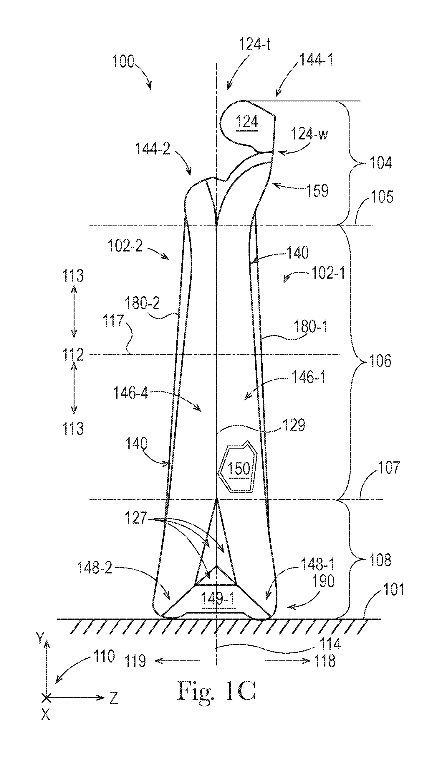
FIG. 1C illustrates a left side view of the stand up flexible container of FIG. 1A.
FIG. 1D illustrates a right side view of the stand up flexible container of FIG. 1A.
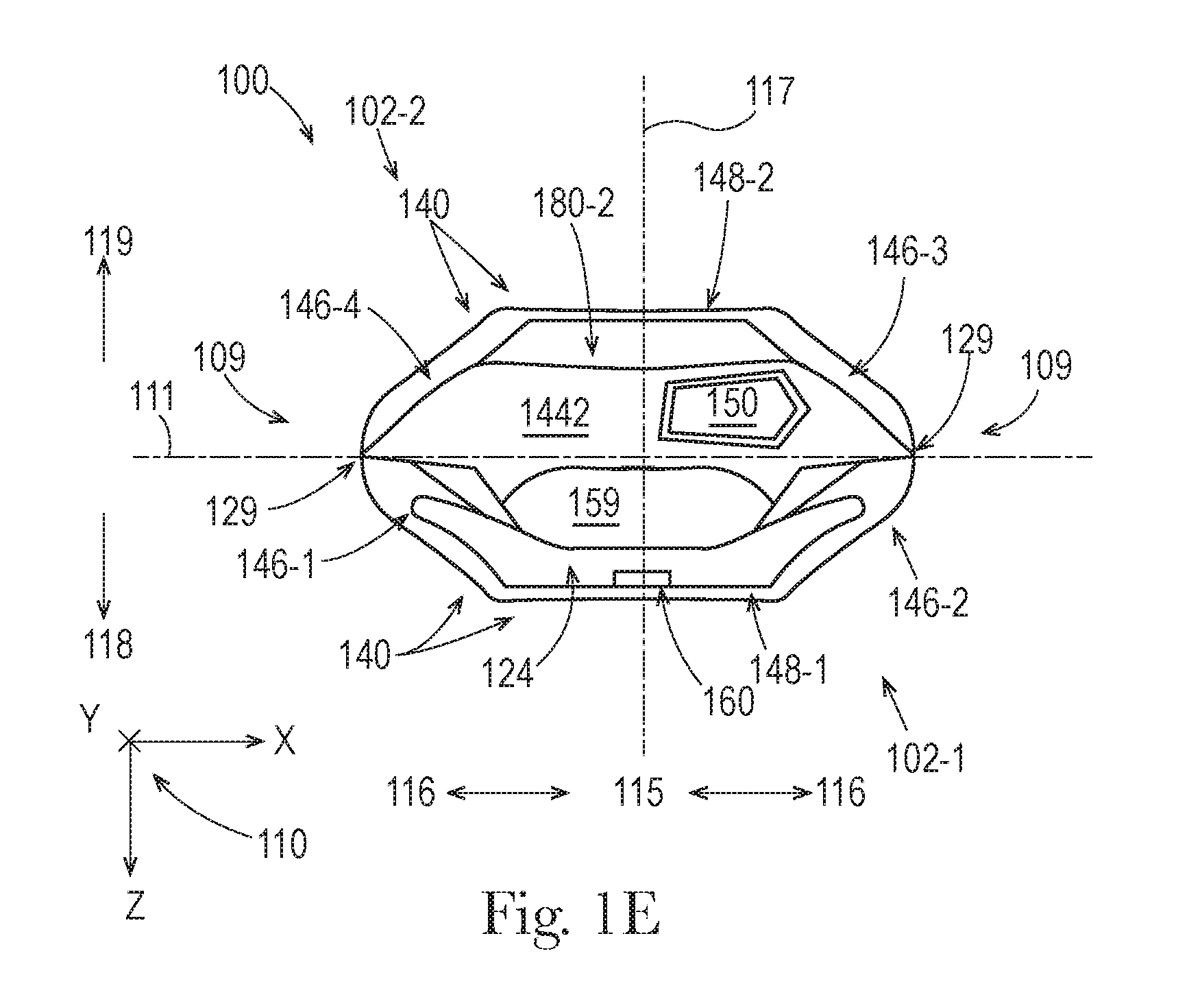
FIG. 1E illustrates a top view of the stand up flexible container of FIG. 1A.
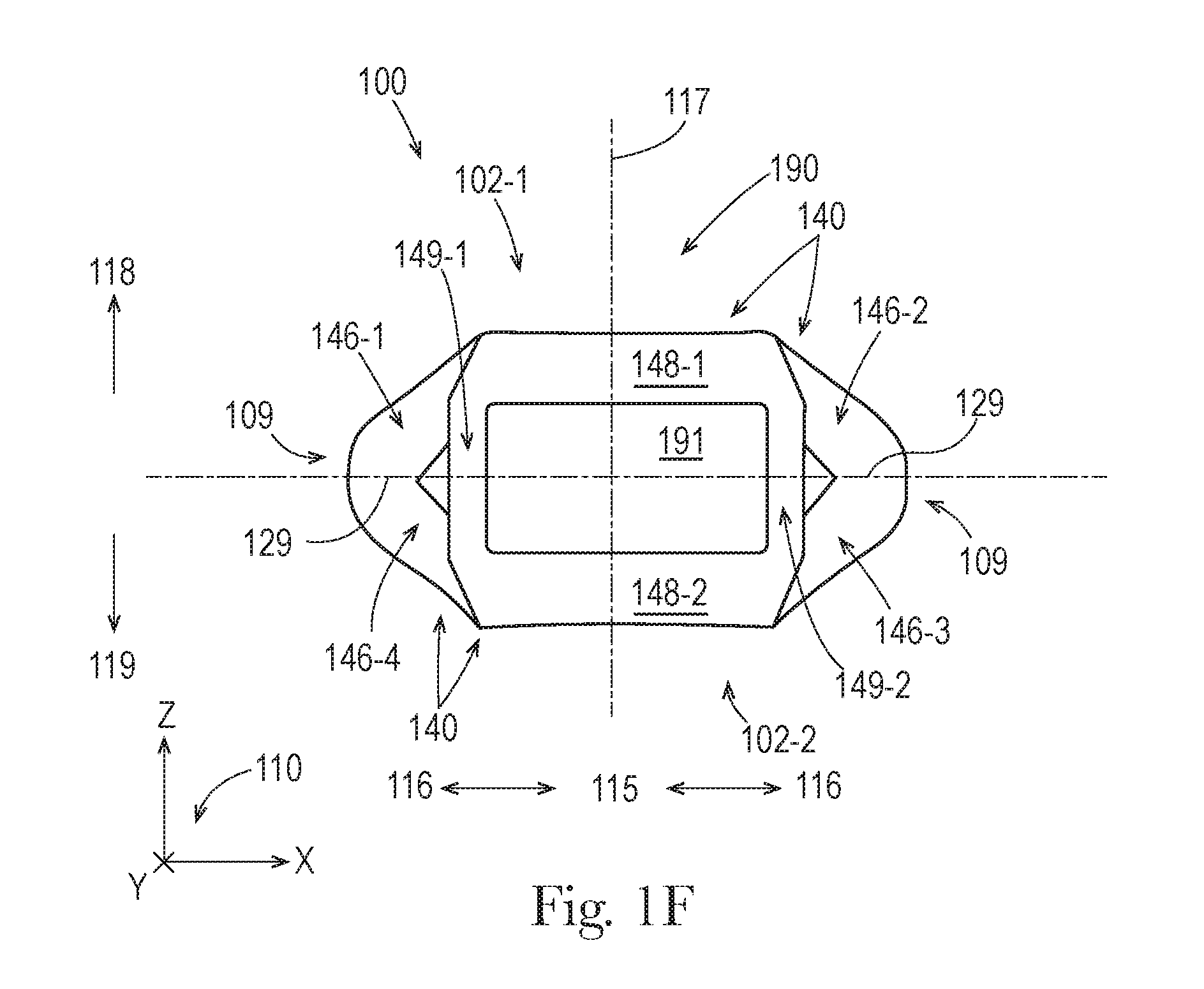
FIG. 1F illustrates a bottom view of the stand up flexible container of FIG. 1A.
FIG. 1G illustrates a perspective view of the stand up flexible container of FIG. 1A.
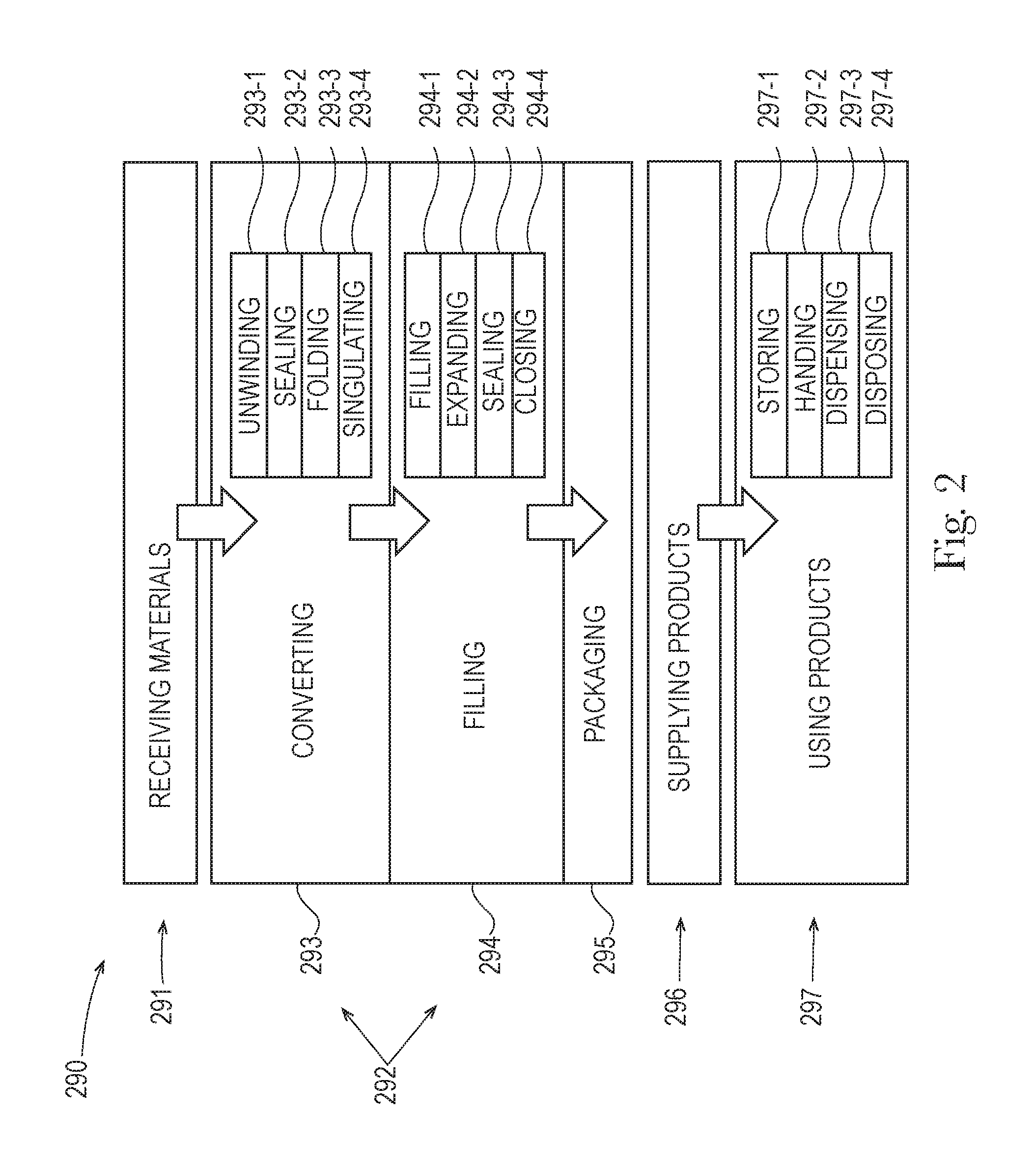
FIG. 2 is a flowchart illustrating a process of how a flexible container is made, supplied, and used.
FIG. 3 illustrates a left side view of the stand up flexible container of FIG. 1A.
DETAILED DESCRIPTION
The present disclosure describes various embodiments of containers made from flexible material. Because these containers are made from flexible material, these containers offer a number of advantages, when compared with conventional rigid containers.
Even though the containers of the present disclosure are made from flexible material, they can be configured with sufficient structural integrity, such that they can receive, contain, and dispense fluent product(s), as intended, without failure. Also, these containers can be configured with sufficient structural integrity, such that they can withstand external forces and environmental conditions from handling, without failure. Further, these containers can be configured with structures that allow them to be displayed for sale and put into use, as intended, without failure.
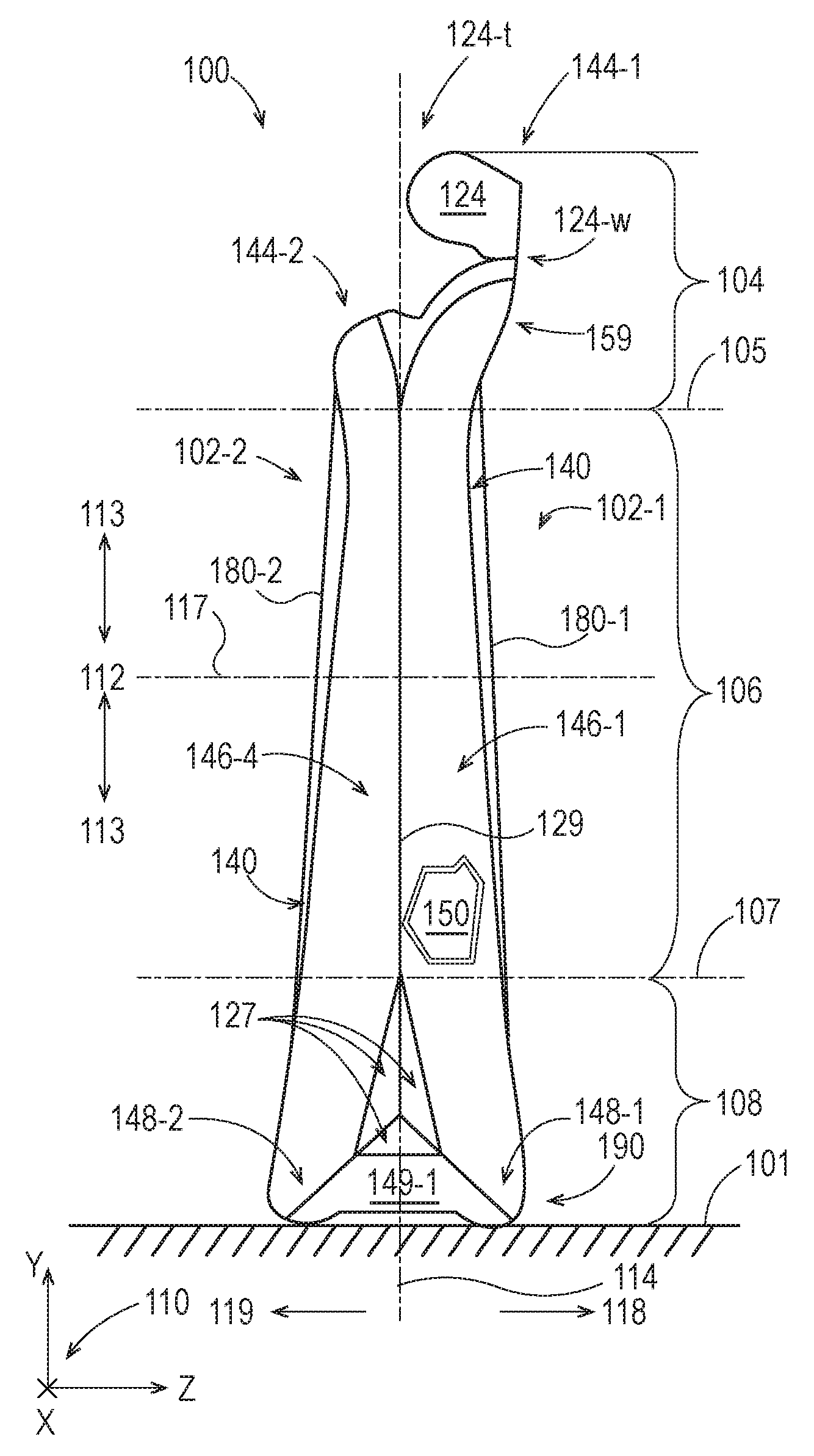
FIGS. 1A-1G illustrate various views of an embodiment of a stand up flexible container 100. FIG. 1A illustrates a front view of the container 100. The container 100 is standing upright on a horizontal support surface 101. The flexible container 100 is a film-based container, made entirely of film laminates.
In the embodiments of FIG. 1A-1G, a coordinate system 110, provides lines of reference for referring to directions in the figure. The coordinate system 110 is a three-dimensional Cartesian coordinate system with an X-axis, a Y-axis, and a Z-axis, wherein each axis is perpendicular to the other axes, and any two of the axes define a plane. The X-axis and the Z-axis are parallel with the horizontal support surface 101 and the Y-axis is perpendicular to the horizontal support surface 101.
FIGS. 1A-1G also includes other lines of reference, for referring to directions and locations with respect to the container 100. A lateral centerline 111 runs parallel to the X-axis. An XY plane at the lateral centerline 111 separates the container 100 into a front half and a back half. An XZ plane at the lateral centerline 111 separates the container 100 into an upper half and a lower half. A longitudinal centerline 114 runs parallel to the Y-axis. A YZ plane at the longitudinal centerline 114 separates the container 100 into a left half and a right half. A third centerline 117 runs parallel to the Z-axis. The lateral centerline 111, the longitudinal centerline 114, and the third centerline 117 all intersect at a center of the container 100.
A disposition with respect to the lateral centerline 111 defines what is longitudinally inboard 112 and longitudinally outboard 113. A disposition with respect to the longitudinal centerline 114 defines what is laterally inboard 115 and laterally outboard 116. A disposition in the direction of the third centerline 117 and toward a front 102-1 of the container is referred to as forward 118 or in front of. A disposition in the direction of the third centerline 117 and toward a back 102-2 of the container is referred to as backward 119 or behind.
The container 100 includes a gusseted top 104, a middle 106, and a gusseted bottom 108, the front 102-1, the back 102-2, and left and right sides 109. The top 104 is separated from the middle 106 by a reference plane 105, which is parallel to the XZ plane. The middle 106 is separated from the bottom 108 by a reference plane 107, which is also parallel to the XZ plane. The container 100 has an overall height of 100-oh. In the embodiment of FIG. 1A, the front 102-1 and the back 102-2 of the container are joined together at a seal 129, which extends along portions of the sides 109 of the container 100.
The container 100 includes a sealed tear tab 124, a structural support frame 140, a product space 150, a dispenser 160, panels 180-1 and 180-2, and a base structure 190. A portion of panel 180-1 is illustrated as broken away, in order to illustrate the product space 150. The product space 150 is configured to contain one or more fluent products.
The tear tab 124 is formed at the distal end of a sealed leg 144-1 of a top gusset, disposed in the top 104 of the container 100, and in the front 102-1. When the tear off portion 124 is removed, by pulling on a protruding tab 124-t, and causing separation along a line of weakness 124-w, the container 100 can dispense fluent product(s) from the product space 150 through a flow channel 159 then through the dispenser 160, to the environment outside of the container 100. In the embodiment of FIGS. 1A-1D, the dispenser 160 is disposed in the top 104, however, in various alternate embodiments, the dispenser 160 can be disposed anywhere else on the top 140, middle 106, or bottom 108, including anywhere on either of the sides 109, on either of the panels 180-1 and 180-2, and on any part of the base 190 of the container 100. The structural support frame 140 supports the mass of fluent product(s) in the product space 150, and makes the container 100 stand upright.
The panels 180-1 and 180-2 are squeeze panels, made of a film laminate. Panel 180-1 overlays a front of the product space 150. Substantially all of a periphery of the panel 180-1 is surrounded by a front panel seal 121-1. Panel 180-2 overlays a back of the product space 150. Substantially all of a periphery of the panel 180-2 is surrounded by a back panel seal 121-2. The panels 180-1 and 180-2 are relatively flat surfaces, suitable for displaying any kind of indicia. However, in various embodiments, part, parts, or about all, or approximately all, or substantially all, or nearly all, or all of either or both of the panels 180-1 and 180-2 can include one or more curved surfaces. The base structure 190 is part of the structural support frame 140 and provides stability to the container 100 as it stands upright.
The structural support frame 140 is formed by a plurality of structural support members, each of which is an expanded structural support volume, made from a film laminate. The structural support frame 140 includes top structural support member 144-2, middle structural support members 146-1, 146-2, 146-3, and 146-4, as well as bottom structural support members 148-1 and 148-2.
The top structural support member 144-2 is formed in a folded leg of a top gusset, disposed in the top 104 of the container 100, and in the back 102-2. The top structural support member 144-2 is adjacent to the sealed leg 144-1 of the top gusset that includes the flow channel 159 and the dispenser 160. The flow channel 158 allows the container 100 to dispense fluent product(s) from the product space 150 through the flow channel 159 then through the dispenser 160.
The top structural support member 144-2 is disposed above substantially all of the product space 150. Overall, the top structural support member 144-2 is oriented about horizontally, but with its ends curved slightly downward. The top structural support member 144-2 has a cross-sectional area that is substantially uniform along its length; however the cross-sectional areas at its ends are slightly larger than the cross-sectional area in its middle.
The middle structural support members 146-1, 146-2, 146-3, and 146-4 are disposed on the left and right sides 109, from the top 104, through the middle 106, into the bottom 108. The middle structural support member 146-1 is disposed in the front 102-1, on the left side 109; the middle structural support member 146-4 is disposed in the back 102-2, on the left side 109, behind the middle structural support member 146-1. The middle structural support members 146-1 and 146-4 are adjacent to each other and in contact with each other along parts of their lengths, except that a lower portion of the middle structural support member 146-1 and a lower portion of the middle structural support member 146-4 are spaced apart from each other by a reinforcing seal 127. In various embodiments, the middle structural support members 146-1 and 146-4 can be in contact with each other at one or more relatively smaller locations and/or at one or more relatively larger locations, along part, or parts, or about all, or approximately all, or substantially all, or nearly all, or all of their overall lengths. The middle structural support members 146-1 and 146-4 are not directly connected to each other. However, in various alternate embodiments, the middle structural support members 146-1 and 146-4 can be directly connected and/or joined together along part, or parts, or about all, or approximately all, or substantially all, or nearly all, or all of their overall lengths.
The middle structural support member 146-2 is disposed in the front 102-1, on the right side 109; the middle structural support member 146-3 is disposed in the back 102-2, on the right side 109, behind the middle structural support member 146-2. The middle structural support members 146-2 and 146-3 are adjacent to each other and in contact with each other along substantially all of their lengths, except that a lower portion of the middle structural support member 146-2 and a lower portion of the middle structural support member 146-3 are spaced apart from each other by a reinforcing seal 127. In various embodiments, the middle structural support members 146-2 and 146-3 can be in contact with each other at one or more relatively smaller locations and/or at one or more relatively larger locations, along part, or parts, or about all, or approximately all, or substantially all, or nearly all, or all of their overall lengths. The middle structural support members 146-2 and 146-3 are not directly connected to each other. However, in various alternate embodiments, the middle structural support members 146-2 and 146-3 can be directly connected and/or joined together along part, or parts, or about all, or approximately all, or substantially all, or nearly all, or all of their overall lengths.
The middle structural support members 146-1, 146-2, 146-3, and 146-4 are disposed substantially laterally outboard from the product space 150. Overall, each of the middle structural support members 146-1, 146-2, 146-3, and 146-4 is oriented about vertically, but angled slightly, with its lower end angled laterally outboard and its upper end angled laterally inboard. Each of the middle structural support members 146-1, 146-2, 146-3, and 146-4 has a cross-sectional area that varies along its length.
The bottom structural support members 148-1 and 148-2 are disposed on the bottom 108 of the container 100, each formed in one folded leg of a bottom gusset. The bottom structural support member 148-1 is disposed in the front 102-1 and the bottom structural support member 148-2 is disposed in the back 102-2, behind the bottom structural support member 148-1. The bottom structural support members 148-1 and 148-2 are substantially parallel to each other but are offset from each other and not in contact with each other.
The bottom structural support members 148-1 and 148-2 are disposed below substantially all of the product space 150, and are part of the base structure 190. Overall, each of the bottom structural support members 148-1 and 148-2 is oriented horizontally and substantially laterally, with its outward facing ends curved slightly upward. Each of the bottom structural support members 148-1 and 148-2 has a cross-sectional area that is substantially uniform along its length. For each of the bottom structural support members 148-1 and 148-2, substantially all of the overall length of the bottom structural support member is in contact with the horizontal support surface 101, when the container is standing up on the horizontal support surface 101. However, in various embodiments, about all, or approximately all, or substantially all, or nearly all, or all of a bottom structural support member may contact a horizontal support surface.
The bottom structural support members 148-1 and 148-2 are connected to each other by bottom middle structural support members 149-1 and 149-2, which are also part of the base structure 190. Overall, each of the bottom middle structural support members 148-1 and 148-2 is oriented horizontally and substantially parallel to a third centerline of a container. Each of the bottom middle structural support members 149-1 and 149-2 has a cross-sectional area that is smaller in its middle and larger at its ends. Each of the bottom middle structural support members 149-1 and 149-2 is in contact with the horizontal support 101 surface at its ends, but not at its middle, when the container is standing up on the horizontal support surface 101. However, in various embodiments, about all, or approximately all, or substantially all, or nearly all, or all of a bottom middle structural support member may contact a horizontal support surface.
In the base structure 190, the right end of the bottom structural support member 148-1 is joined to the front end of the bottom middle structural support member 149-2; the back end of the bottom middle structural support member 149-2 is joined to the right end of the bottom structural support member 148-2; the left end of the bottom structural support member 148-2 is joined to the back end of the bottom middle structural support member 149-1; and the front end of the bottom middle structural support member 149-1 is joined to the left end of the bottom structural support member 148-1.
The structural support members 148-1, 149-2, 148-2, and 149-1, together surround all of a bottom panel 191, which has an overall shape that is substantially rectangular, with rounded corners. In various embodiments, structural support members may surround about all, or approximately all, or substantially all, or nearly all of a bottom panel. In alternative embodiments, any number of structural support members can be used to partially or fully surround a bottom panel having any shape. The bottom panel is made of a film laminate and is disposed below and adjacent to a bottom portion of the product volume 150. In the embodiment of FIGS. 1A-1G, no part of the bottom panel 191 contacts the horizontal support surface 101 but all of the bottom panel 191 is raised off of the horizontal support surface 101; however, in various embodiments, approximately all, or substantially all, or nearly all, of a bottom panel may be raised off of a horizontal support surface while part, parts, or all of a bottom panel may contact a horizontal support surface. In some embodiments, part, parts, or all of a bottom panel may be transparent, such that the product volume can be viewed through the bottom panel.
Each of the reinforcing seals 127 is formed by sealed portions that are bounded by edges that are shared with the bottom portions of middle structural support members and a middle portion of a bottom middle structural support member, on each side, such that each reinforcing seal 127 has an overall shape that is a substantially triangular shape. On the left side 109 of the container 100, the reinforcing seal 127 is formed by sealed portions that are bounded by edges that are shared with the bottom portion of middle structural support members 146-1 and 146-4 and a middle portion of a bottom middle structural support member 149-1. On the right side 109 of the container 100, the reinforcing seal 127 is formed by sealed portions that are bounded by edges that are shared with the bottom portion of middle structural support members 146-2 and 146-3 and a middle portion of a bottom middle structural support member 149-2.
In the front portion of the structural support frame 140, the upper end of the middle structural support member 146-1 is a free end disposed toward one side 109 of the container 100; the lower end of the middle structural support member 146-1 is joined to the left end of the bottom structural support member 148-1; the right end of the bottom structural support member 148-1 is joined to the lower end of the middle structural support member 146-2; and the upper end of the middle structural support member 146-2 is a free end disposed toward another side 109 of the container 100. The structural support members 146-1, 148-1, and 146-2, together surround substantially all of the panel 180-1, except for a gap between the upper end of the middle structural support member 146-1 and the upper end of the middle structural support member 146-2, which are not connected by a structural support member, to provide an unobstructed pathway for the flow channel 159.
Similarly, in the back portion of the structural support frame 140, the left end of the top structural support member 144-2 is joined to the upper end of the middle structural support member 146-4; the lower end of the middle structural support member 146-4 is joined to the left end of the bottom structural support member 148-2; the right end of the bottom structural support member 148-2 is joined to the lower end of the middle structural support member 146-3; and the upper end of the middle structural support member 146-3 is joined to the right end of the top structural support member 144-2. The structural support members 144-2, 146-2, 148-2, and 146-2, together surround substantially all of the panel 180-2.
In the structural support frame 140, the ends of the structural support members, which are joined together, are directly connected, around the periphery of their walls. However, in various alternative embodiments, any of the structural support members 144-2, 146-1, 146-2, 146-3, 146-4, 148-1, and 148-2 can be joined together in any way described herein or known in the art.
In alternative embodiments of the structural support frame 140, adjacent structural support members can be combined into a single structural support member, wherein the combined structural support member can effectively substitute for the adjacent structural support members, as their functions and connections are described herein. In other alternative embodiments of the structural support frame 140, one or more additional structural support members can be added to the structural support members in the structural support frame 140, wherein the expanded structural support frame can effectively substitute for the structural support frame 140, as its functions and connections are described herein. Also, in some alternative embodiments, a flexible container may not include a base structure.
FIG. 1B illustrates a back view of the stand up flexible container of FIG. 1A.
FIG. 1C illustrates a left side view of the stand up flexible container of FIG. 1A.
FIG. 1D illustrates a right side view of the stand up flexible container of FIG. 1A.
FIG. 1E illustrates a top view of the stand up flexible container of FIG. 1A.
FIG. 1F illustrates a bottom view of the stand up flexible container of FIG. 1A.
FIG. 1G illustrates a perspective view of the stand up flexible container of FIG. 1A.
FIG. 2 is a flowchart illustrating a process 290 of how a product with a flexible container is made, supplied, and used. The process 290 begins with receiving 291 materials, then continues with the making 292 of the product, followed by supplying 296 the product, and finally ends with using 297 the product.
The receiving 291 of materials can include receiving any materials and/or ingredients for making the product (e.g. ingredients for making a fluent product) and/or the container for the product (e.g. flexible materials to be converted into a flexible container). The flexible materials can be any kind of suitable flexible material, as disclosed herein and/or as known in the art of flexible containers and/or in U.S. non-provisional patent application Ser. No. 13/889,061 filed May 7, 2013, entitled "Flexible Materials for Flexible Containers" published as US20130337244 and/or in US non-provisional patent application Ser. No. 13/889,090 filed May 7, 2013, entitled "Flexible Materials for Flexible Containers" published as US20130294711, and/or US provisional patent application 62/186,704 filed Jun. 30, 2015 entitled "Flexible Containers with Removable Portions," each of which is hereby incorporated by reference.
The making 292 includes the processes of converting 293, filling 294, and packaging 295. The converting 293 process is the process for transforming one or more flexible materials and/or components, from the receiving 291, into a flexible container, as described herein. The converting 293 process includes the further processes of unwinding 293-1, sealing 293-2, and folding 293-3 the flexible materials then (optionally) singulating 293-4 the flexible materials into individual flexible containers. The filling process 294 includes the further processes of filling 294-1 one or more product spaces of the individual flexible containers, from the converting 293, with one or more fluent products, expanding 294-2 one or more structural support volumes with one or more expansion materials, then sealing 294-3 the one or structural support frames and sealing 294-3 and/or closing 294-4 the one or more product spaces. The packaging 295 process includes placing the filled product with a flexible container, from the filling 294, into one or more packages (e.g. cartons, cases, shippers, etc.) as known in the art of packaging. In various embodiments of the process 290, the packaging 295 process may be omitted. In various embodiments, the processes of making 292 can be performed in various orders, and additional/alternate processes for making flexible containers can be performed.
Any of the making 292 processes can be accomplished according to any of the embodiments described here and/or as known in the art of making flexible containers and/or in U.S. non-provisional patent application Ser. No. 13/957,158 filed Aug. 1, 2013, entitled "Methods of Making Flexible Containers" published as US20140033654 and/or in U.S. non-provisional patent application Ser. No. 13/957,187 filed Aug. 1, 2013, entitled "Methods of Making Flexible Containers" published as US20140033655 and/or in U.S. non-provisional patent application Ser. No. 14/448,491 filed Jul. 31, 2014, entitled "Methods of Forming a Flexible Container" published as US20150033671 and/or in U.S. non-provisional patent application Ser. No. 14/534,197 filed Nov. 6, 2014, entitled "Flexible Containers and Methods of Forming the Same" published as US20150126349 and/or in U.S. non-provisional patent application Ser. No. 14/534,210 filed Nov. 6, 2014, entitled "Flexible Containers and Methods of Forming the Same" published as US 20150125099 and/or in U.S. non-provisional patent application Ser. No. 14/534,213 filed Nov. 6, 2014, entitled "Flexible Containers and Methods of Making the Same" published as US 20150122373 and/or in U.S. non-provisional patent application Ser. No. 14/534,214 filed Nov. 6, 2013, entitled "Flexible Containers and Methods of Making the Same" published as US20150121810, each of which is hereby incorporated by reference.
A machine for making 292 a flexible container, as described in connection with embodiments of FIG. 2, can include a particular set of unit operations for sealing (e.g. sealing 293-2) flexible materials with a particular sealing pattern, resulting in a flexible container with a particular sealed configuration, as described herein.
A machine for making 292 a flexible container, as described in connection with embodiments of FIG. 2, can include a particular set of unit operations for folding (e.g. folding 293-3) flexible materials with a particular folding pattern, resulting in a flexible container with a particular folded configuration, as described herein.
The supplying 296 of the product includes transferring the product, from the making 292, to product purchasers and/or ultimately to product users, as known in the art of supplying. The using 297 of the product includes the processes of storing 297-1, handling 297-2, dispensing 297-3, and disposing 297-4 of the product, as described herein and is known in the art of using products with flexible containers. Part, parts, or all of the process 290 can be used to make products with flexible containers of the present disclosure, including products with line-ups of flexible containers.
FIG. 3 illustrates a left side view of a stand up flexible container 100, which is the same as the flexible container 100 of FIGS. 1A-1G, with further details provided below.
In the flexible container 100, the middle structural support member 146-1 is a front middle structural support member, which includes an upper portion 146-1u, a middle portion 146-1m, and a lower portion 146-11. In the flexible container 100, the middle structural support member 146-4 is a back middle structural support member, which includes an upper portion 146-4u, a middle portion 146-4m, and a lower portion 146-41. In a lower half of the container 100, the front middle structural support member 146-1 is symmetrical with the back middle structural support member 146-4 with respect to a plane that separates the container into a front half and a back half; although in various embodiments these portions of these structural support members may not be symmetrical.
The upper portion 146-1u is spaced apart from the upper portion 146-4u, where the front middle structural support member 146-1 and the back middle structural support member 146-4 diverge in the top 104 of the container 100, toward separate top gussets. The middle portion 146-1m is in contact with the middle portion 146-4m, through at least a portion of the middle 106 of the container 100. The lower portion 146-11 is spaced apart from the lower portion 146-41, where the front middle structural support member 146-1 and the back middle structural support member 146-4 diverge in the bottom 108 of the container 100, toward separate bottom gussets.
The upper portion 146-1u has an upper portion length 146-1u1 measured from an intersection of a centerline of the front middle structural support member 146-1 and the upper end of the upper portion 146-1u, along the centerline, to an intersection of a centerline of the front middle structural support member 146-1 and the lower end of the upper portion 146-1u. Similarly, the upper portion 146-4u has an upper portion length 146-4u1 measured from an intersection of a centerline of the back middle structural support member 146-4 and the upper end of the upper portion 146-4u, along the centerline, to an intersection of a centerline of the back middle structural support member 146-4 and the lower end of the upper portion 146-4u.
In various embodiments, the upper portion length 146-1u1 can be 0-30% of the overall length of the front middle structural support member 146-1, which is measured from an intersection of the centerline of the front middle structural support member 146-1 and the upper end of the upper portion 146-1u, along the length of its centerline, to an intersection of a centerline of the front middle structural support member 146-1 and the lower end of the lower portion 146-11. The upper portion length 146-1u1 can be also be any integer value for percentage between 0-30% of the overall length of the front middle structural support member 146-1, and any range formed by any of these values, such as 0-20%, 0-10%, 10-30%, 20-30%, 10-20%, etc.
In various embodiments, the upper portion length 146-4u1 can be 0-30% of the overall length of the back middle structural support member 146-4, which is measured from an intersection of the centerline of the back middle structural support member 146-4 and the upper end of the upper portion 146-4u, along the length of its centerline, to an intersection of a centerline of the back middle structural support member 146-4 and the lower end of the lower portion 146-41. The upper portion length 146-4u1 can be also be any integer value for percentage between 0-30% of the overall length of the back middle structural support member 146-4, and any range formed by any of these values, such as 0-20%, 0-10%, 10-30%, 20-30%, 10-20%, etc.
The middle portion 146-1m has a middle portion length 146-1m1 measured from an intersection of a centerline of the front middle structural support member 146-1 and the upper end of the middle portion 146-1m, along the centerline, to an intersection of a centerline of the front middle structural support member 146-1 and the lower end of the middle portion 146-1m. Similarly, the middle portion 146-4m has a middle portion length 146-4m1 measured from an intersection of a centerline of the back middle structural support member 146-4 and the upper end of the middle portion 146-4m, along the centerline, to an intersection of a centerline of the back middle structural support member 146-4 and the lower end of the middle portion 146-4m.
In various embodiments, the middle portion length 146-1m1 can be 0-90% of the overall length of the front middle structural support member 146-1. The middle portion length 146-1m1 can be also be any integer value for percentage between 0-90% of the overall length of the front middle structural support member 146-1, and any range formed by any of these values, such as 0-60%, 0-40%, 30-90%, 35-90%, 40-90%, 50-90%, 30-60%, etc.
In various embodiments, the middle portion length 146-4m1 can be 0-90% of the overall length of the back middle structural support member 146-4. The middle portion length 146-4m1 can be also be any integer value for percentage between 0-30% of the overall length of the back middle structural support member 146-4, and any range formed by any of these values, such as 0-60%, 0-40%, 30-90%, 40-90%, 30-60%, etc.
The lower portion 146-11 has a lower portion length 146-111 measured from an intersection of a centerline of the front middle structural support member 146-1 and the upper end of the lower portion 146-11, along the centerline, to an intersection of a centerline of the front middle structural support member 146-1 and the lower end of the lower portion 146-11. Similarly, the lower portion 146-41 has a lower portion length 146-411 measured from an intersection of a centerline of the back middle structural support member 146-4 and the upper end of the lower portion 146-41, along the centerline, to an intersection of a centerline of the back middle structural support member 146-4 and the lower end of the lower portion 146-41.
In various embodiments, the lower portion length 146-111 can be 0-50% of the overall length of the front middle structural support member 146-1. The lower portion length 146-111 can be also be any integer value for percentage between 0-90% of the overall length of the front middle structural support member 146-1, and any range formed by any of these values, such as 0-40%, 0-30%, 10-50%, 15-50%, 20-50%, 25-50%, 10-40%, etc.
In various embodiments, the lower portion length 146-411 can be 0-50% of the overall length of the back middle structural support member 146-4. The lower portion length 146-411 can be also be any integer value for percentage between 0-30% of the overall length of the back middle structural support member 146-4, and any range formed by any of these values, such as 0-40%, 0-30%, 10-50%, 20-50%, 10-40%, etc.
The lower portion 146-11 is spaced apart from the lower portion 146-41 by the reinforcing seal 127. Since the reinforcing seal 127 has an overall shape that is a substantially triangular shape with its top disposed toward the top 104 of the container 100, the spaced apart distance between the lower portion 146-11 and the lower portion 146-41 increases from the upper part of the reinforcing seal 127 to the lower part of the reinforcing seal, toward the bottom 108 of the container 100.
At the lowest part of the reinforcing seal 127, the reinforcing seal 127 provides a largest spaced apart difference 127-1d. The largest spaced apart difference 127-1d can be 0.1-20.0 centimeters, or any value in increments of 0.1 from 0.5-20.0 centimeters, or any range formed by any of these values, such as 0.5-10.0 centimeters, 0.8-7.0 centimeters, 1.0-5.0 centimeters, 1.5-4.0 centimeters, 2.0-3.0 centimeters, etc. In some embodiments, the largest spaced apart difference 127-1d can be larger than a largest cross-sectional dimension of the front middle structural support member 146-1 at its lower end and/or larger than a largest cross-sectional dimension of the back middle structural support member 146-4 at its lower end. In various embodiments, the largest spaced apart difference 127-1d can be larger than any cross-sectional dimension of the front middle structural support member 146-1 and/or larger than any cross-sectional dimension of the back middle structural support member 146-4.
The structure of the bottom 108 of the right side 109 of the container 100 is symmetrical with the structure of the bottom 108 of the left side 109 of the container 100 with respect to a plane that separates the container into a left half and a right half; although in various embodiments these structures may not be symmetrical.
Part, parts, or all of any of the embodiments disclosed herein also can be combined with part, parts, or all of other embodiments known in the art of containers for fluent products, so long as those embodiments can be applied to flexible containers, as disclosed herein.
The packages described herein, may be used across a variety of industries for a variety of products. For example, any embodiment of a package, as described herein may be used for receiving, containing, storing, and/or dispensing any fluent product in the consumer products industry, including any of the following products, any of which can take any product form described herein or known in the art: baby care products (e.g. soaps, shampoos, and lotions); beauty care products for cleaning, treating, beautifying, and/or decorating human hair (e.g. hair shampoos, hair conditioners, hair dyes, hair colorants, hair repair products, hair growth products, hair removal products, hair minimization products, etc.); beauty care products for cleaning, treating, beautifying, and/or decorating human skin (e.g. soaps, body washes, body scrubs, facial cleansers, astringents, sunscreens, sun block lotions, lip balms, cosmetics, skin conditioners, cold creams, skin moisturizers, antiperspirants, deodorants, etc.); beauty care products for cleaning, treating, beautifying, and/or decorating human nails (e.g. nail polishes, nail polish removers, etc.); grooming products for cleaning, treating, beautifying, and/or decorating human facial hair (e.g. shaving products, pre-shaving products, after shaving products, etc.); health care products for cleaning, treating, beautifying, and/or decorating human oral cavities (e.g. toothpaste, mouthwash, breath freshening products, anti-plaque products, tooth whitening products, etc.); health care products for treating human health conditions (e.g. medicines, medicaments, pharmaceuticals, vitamins, nutraceuticals, nutrient supplements (for calcium, fiber, etc.), cough treatment products, cold remedies, lozenges, treatments for respiratory and/or allergy conditions, pain relievers, sleep aids, gastrointestinal treatment products (for heartburn, upset stomach, diarrhea, irritable bowel syndrome, etc.), purified water, treated water, etc.); fabric care products for cleaning, conditioning, refreshing and/or treating fabrics, clothes, and/or laundry (e.g. laundry detergents, fabric conditioners, fabric dyes, fabric bleaches, etc.); dish care products for home, commercial, and/or industrial use (e.g. dish soaps and rinse aids for hand-washing and/or machine washing); cleaning and/or deodorizing products for home, commercial, and/or industrial use (e.g. soft surface cleaners, hard surface cleaners, glass cleaners, ceramic tile cleaners, carpet cleaners, wood cleaners, multi-surface cleaners, surface disinfectants, kitchen cleaners, bath cleaners (e.g. sink, toilet, tub, and/or shower cleaners), appliance cleaning products, appliance treatment products, car cleaning products, car deodorizing products, air cleaners, air deodorizers, air disinfectants, etc.), and the like.
Although the present disclosure describes its embodiments with respect to consumer products, they can also be similarly applied outside of the consumer products industry, including: the areas of home, commercial, and/or industrial, building and/or grounds, construction and/or maintenance; the food and beverage industry; the medical industry, in the areas of medicines, medical devices, and medical treatment; and all industries that use internal combustion engines (such as the transportation industry, and the power equipment industry, the power generation industry, etc.).
Definitions
As used herein, the term "about" modifies a particular value, by referring to a range equal to the particular value, plus or minus twenty percent (+/-20%). For any of the embodiments of flexible containers, disclosed herein, any disclosure of a particular value, can, in various alternate embodiments, also be understood as a disclosure of a range equal to about that particular value (i.e. +/-20%).
As used herein, the term "approximately" modifies a particular value, by referring to a range equal to the particular value, plus or minus fifteen percent (+/-15%). For any of the embodiments of flexible containers, disclosed herein, any disclosure of a particular value, can, in various alternate embodiments, also be understood as a disclosure of a range equal to approximately that particular value (i.e. +/-15%).
As used herein, the term "atmospheric pressure" refers to an absolute pressure of 1 atmosphere.
As used herein, when referring to a flexible container, the term "bottom" refers to the portion of the container that is located in the lowermost 30% of the overall height of the container, that is, from 0-30% of the overall height of the container. As used herein, the term bottom can be further limited by modifying the term bottom with a particular percentage value, which is less than 30%. For any of the embodiments of flexible containers, disclosed herein, a reference to the bottom of the container can, in various alternate embodiments, refer to the bottom 25% (i.e. from 0-25% of the overall height), the bottom 20% (i.e. from 0-20% of the overall height), the bottom 15% (i.e. from 0-15% of the overall height), the bottom 10% (i.e. from 0-10% of the overall height), or the bottom 5% (i.e. from 0-5% of the overall height), or any integer value for percentage between 0% and 30%.
As used herein, the term "directly connected" refers to a configuration wherein elements are attached to each other without any intermediate elements therebetween, except for any means of attachment (e.g. adhesive).
As used herein, when referring to a flexible container, the term "dispenser" refers to a structure configured to dispense fluent product(s) from a product space and/or from a mixing volume to the environment outside of the container. For any of the flexible containers disclosed herein, any dispenser can be configured in any way disclosed herein or known in the art, including any suitable size, shape, and flow rate. For example, a dispenser can be a push-pull type dispenser, a dispenser with a flip-top cap, a dispenser with a screw-on cap, a rotatable type dispenser, dispenser with a cap, a pump type dispenser, a pump spray type dispenser, a trigger spray type dispenser, a straw dispenser, a flip up straw dispenser, a straw dispenser with bite valve, a dosing dispenser, etc. A dispenser can be a parallel dispenser, providing multiple flow channels in fluid communication with multiple product spaces, wherein those flow channels remain separate until the point of dispensing, thus allowing fluent products from multiple product spaces to be dispensed as separate fluent products, dispensed together at the same time. A dispenser can be a mixing dispenser, providing one or more flow channels in fluid communication with multiple product spaces, with multiple flow channels combined before the point of dispensing, thus allowing fluent products from multiple product spaces to be dispensed as the fluent products mixed together. As another example, a dispenser can be formed by a frangible opening. As further examples, a dispenser can utilize one or more valves and/or dispensing mechanisms disclosed in the art, such as those disclosed in: US provisional patent application 62/157,766 filed May 6, 2015 entitled "Methods of Forming Flexible Containers with Gussets"; published US patent application 2003/0096068, entitled "One-way valve for inflatable package"; U.S. Pat. No. 4,988,016 entitled "Self-sealing container"; and U.S. Pat. No. 7,207,717, entitled "Package having a fluid actuated closure"; each of which is hereby incorporated by reference. Still further, any of the dispensers disclosed herein, may be incorporated into a flexible container either directly (e.g. formed by one or more flexible materials that are integral with the flexible container), or in combination with one or more other materials or structures (such as a fitment), or in any way known in the art. In some alternate embodiments, dispensers disclosed herein can be configured for both dispensing and filling, to allow filling of product space(s) through one or more dispensers. In other alternate embodiments, a product space can include one or more filling structure(s) (e.g. for adding water to a mixing volume) in addition to or instead of one or more dispenser(s). Any location for a dispenser, disclosed herein can alternatively be used as a location for a filling structure. In some embodiments, a product space can include one or more filling structures in addition to any dispenser(s). And, any location for a dispenser, disclosed herein can alternatively be used as a location for an opening, through which product can be filled and/or dispensed, wherein the opening may be reclosable or non-reclosable, and can be configured in any way known in the art of packaging. For example, an opening can be: a line of weakness, which can be torn open; a zipper seal, which can be pulled open and pressed closed (e.g. a press seal), or opened and closed with a slider; openings with adhesive-based closures; openings with cohesive-based closures; openings with closures having fasteners (e.g. snaps, tin tie, etc.), openings with closures having micro-sized fasteners (e.g. with opposing arrays of interlocking fastening elements, such as hook, loops, and/or other mating elements, etc.), and any other kind of opening for packages or containers, with or without a closure, known in the art.
As used herein, when referring to a flexible container, the term "disposable" refers to a container which, after dispensing a product to an end user, is not configured to be refilled with an additional amount of the product, but is configured to be disposed of (i.e. as waste, compost, and/or recyclable material). Part, parts, or all of any of the embodiments of flexible containers, disclosed herein, can be configured to be disposable.
As used herein, when referring to a flexible container, the term "durable" refers to a container that is reusable more than non-durable containers.
As used herein, when referring to a flexible container, the term "expanded" refers to the state of one or more flexible materials that are configured to be formed into a structural support volume, after the structural support volume is made rigid by one or more expansion materials. An expanded structural support volume has an overall width that is significantly greater than the combined thickness of its one or more flexible materials, before the structural support volume is filled with the one or more expansion materials. Examples of expansion materials include liquids (e.g. water), gases (e.g. compressed air), fluent products, foams (that can expand after being added into a structural support volume), co-reactive materials (that produce gas), or phase change materials (that can be added in solid or liquid form, but which turn into a gas; for example, liquid nitrogen or dry ice), or other suitable materials known in the art, or combinations of any of these (e.g. fluent product and liquid nitrogen). In various embodiments, expansion materials can be added at atmospheric pressure, or added under pressure greater than atmospheric pressure, or added to provide a material change that will increase pressure to something above atmospheric pressure. For example, a structural support volume can be expanded by an expansion material at a pressure of 2-20 psi, or any integer value for psi from 2 to 20, or any range formed by any of these values, such as 3-15 psi, 4-11 psi, 5-9 psi, 6-8 psi, etc. For any of the embodiments of flexible containers, disclosed herein, its one or more flexible materials can be expanded at various points in time, with respect to its manufacture, sale, and use, including, for example: before or after its product space(s) are filled with fluent product(s), before or after the flexible container is shipped to a seller, and before or after the flexible container is purchased by an end user.
As used herein, when referring to a product space of a flexible container, the term "filled" refers to the state of the product space in the container (which is fully manufactured) after the filling of its product space(s) with fluent product(s) is complete and the container is fully closed and/or sealed, wherein the container has not been opened or unsealed, and wherein the fluent product(s) in the container have not been put into its/their intended end use.
A filled product space may or may not include an allowance for headspace, depending on the kind of fluent product(s) being contained, and the requirements for containing the fluent product(s).
As an example, a manufacturer can label a flexible container with an external amount indicium that indicates a listed amount of a fluent product that is being offered for sale with the container, can add to the product space of the container an actual amount of the fluent product that is nearly equal to the listed amount (but still includes a headspace that is designed for that fluent product in that product space), and can close the container so the container is configured for retail sale; that container is considered filled. As used herein, the term filled can be modified by using the term filled with a particular percentage value.
As used herein, the term "flat" refers to a surface that is without significant projections or depressions.
As used herein, the term "flexible container" refers to a container with a product space, wherein one or more flexible materials form 50-100% of the overall surface area of the one or more materials that define the three-dimensional space of the product space. For any of the embodiments of flexible containers, disclosed herein, in various embodiments, the flexible container can be configured to have a product space, wherein one or more flexible materials form a particular percentage of the overall area of the one or more materials that define the three-dimensional space, and the particular percentage is any integer value for percentage between 50% and 100%, or within any range formed by any of these values, such as: 60-100%, or 70-100%, or 80-100%, or 90-100%, etc. One kind of flexible container is a film-based container, which is a flexible container made from one or more flexible materials, which include a film.
For any of the embodiments of flexible containers, disclosed herein, in various embodiments, the middle of the flexible container (apart from any fluent product) can be configured to have an overall middle mass, wherein one or more flexible materials form a particular percentage of the overall middle mass, and the particular percentage is any integer value for percentage between 50% and 100%, or within any range formed by any of the preceding values, such as: 60-100%, or 70-100%, or 80-100%, or 90-100%, etc.
For any of the embodiments of flexible containers, disclosed herein, in various embodiments, the entire flexible container (apart from any fluent product) can be configured to have an overall mass, wherein one or more flexible materials form a particular percentage of the overall mass, and the particular percentage is any integer value for percentage between 50% and 100%, or within any range formed by any of the preceding values, such as: 60-100%, or 70-100%, or 80-100%, or 90-100%, etc.
As used herein, the term "flexible material" refers to a thin, easily deformable, sheet-like material, having a flexibility factor within the range of 1,000-2,500,000 N/m. As examples, a flexible material may have a flexibility factor of 1,000-1,250,500 N/m, 1,000-750,700 N/m, 1,000-500,800 N/m, 1,000-250,900 N/m, 1,000-63,475 N/m, 1,000-25,990 N/m, 1,000-13,495 N/m, 13,495-1,250,500 N/m, 25,990-750,700 N/m, 63,475-500,800 N/m, 125,950-250-900 N/m, 13,495-2,500,000 N/m, 12,990-2,500,000 N/m, 63,475-2,500,000 N/m, 125,950-2,500,000 N/m, 250,900-2,500,000 N/m, 500,800-2,500,000 N/m, 750,700-2,500,000 N/m, 1,250,500-2,500,000 N/m, etc. Examples of materials that can be flexible materials include one or more of any of the following: films (such as plastic films), elastomers, foamed sheets, foils, fabrics (including wovens and nonwovens), biosourced materials, and papers, in any configuration, as separate material(s), or as layer(s) of a laminate, or as part(s) of a composite material, in a microlayered or nanolayered structure, with or without one or more of any suitable additives (such as perfumes, dyes, pigments, particles, agents, actives, fillers (e.g. fibers, reinforcing structures), etc.) and in any combination, as described herein or as known in the art.
The flexible materials used to make the containers disclosed herein can be formed in any manner known in the art, and can be joined together using any kind of joining or sealing method known in the art, including, for example, heat sealing (e.g. conductive sealing, impulse sealing, ultrasonic sealing, etc.), welding, crimping, bonding, adhering, and the like, and combinations of any of these.
As used herein, when referring to a flexible container, the term "flexibility factor" refers to a material parameter for a thin, easily deformable, sheet-like material, wherein the parameter is measured in Newtons per meter, and the flexibility factor is equal to the product of the value for the Young's modulus of the material (measured in Pascals) and the value for the overall thickness of the material (measured in meters).
As used herein, when referring to a flexible container, the term "fluent product" refers to one or more liquids and/or pourable solids, and combinations thereof. Examples of fluent products include one or more of any of the following: bites, bits, creams, chips, chunks, crumbs, crystals, emulsions, flakes, gels, grains, granules, jellies, kibbles, liquid solutions, liquid suspensions, lotions, nuggets, ointments, particles, particulates, pastes, pieces, pills, powders, salves, shreds, sprinkles, and the like, either individually or in any combination. Throughout the present disclosure the terms "fluent product" and "flowable product" are used interchangeably and are intended to have the same meaning. Any of the product spaces disclosed herein can be configured to include one or more of any fluent product disclosed herein, or known in the art, in any combination.
As used herein, when referring to a flexible container, the term "formed" refers to the state of one or more materials that are configured to be formed into a product space, after the product space is provided with its defined three-dimensional space.
As used herein, the term "indirectly connected" refers to a configuration wherein elements are attached to each other with one or more intermediate elements therebetween.
As used herein, the term "joined" refers to a configuration wherein elements are either directly connected or indirectly connected.
As used herein, the term "lateral" refers to a direction, orientation, or measurement that is parallel to a lateral centerline of a container, when the container is standing upright or hanging down from a support, as described herein. A lateral orientation may also be referred to a "horizontal" orientation, and a lateral measurement may also be referred to as a "width."
As used herein, the term "like-numbered" refers to similar alphanumeric labels for corresponding elements, as described below. Like-numbered elements have labels with the same last two digits; for example, one element with a label ending in the digits 20 and another element with a label ending in the digits 20 are like-numbered. Like-numbered elements can have labels with a differing first digit, wherein that first digit matches the number for its figure; as an example, an element of FIG. 3 labeled 320 and an element of FIG. 4 labeled 420 are like-numbered. Like-numbered elements can have labels with a suffix (i.e. the portion of the label following the dash symbol) that is the same or possibly different (e.g. corresponding with a particular embodiment); for example, a first embodiment of an element in FIG. 3A labeled 320-a and a second embodiment of an element in FIG. 3B labeled 320-b, are like numbered.
As used herein, the term "longitudinal" refers to a direction, orientation, or measurement that is parallel to a longitudinal centerline of a container, when the container is standing upright on a horizontal support surface or hanging down from a support, as described herein. A longitudinal orientation may also be referred to a "vertical" orientation. When expressed in relation to a horizontal support surface for a container, a longitudinal measurement may also be referred to as a "height", measured above the horizontal support surface.
As used herein, when referring to a flexible container, the term "middle" refers to the portion of the container that is located in between the top of the container and the bottom of the container. As used herein, the term middle can be modified by describing the term middle with reference to a particular percentage value for the top and/or a particular percentage value for the bottom. For any of the embodiments of flexible containers, disclosed herein, a reference to the middle of the container can, in various alternate embodiments, refer to the portion of the container that is located between any particular percentage value for the top, disclosed herein, and/or any particular percentage value for the bottom, disclosed herein, in any combination.
As used herein, the term "nearly" modifies a particular value, by referring to a range equal to the particular value, plus or minus five percent (+/-5%). For any of the embodiments of flexible containers, disclosed herein, any disclosure of a particular value, can, in various alternate embodiments, also be understood as a disclosure of a range equal to approximately that particular value (i.e. +/-5%).
As used herein, when referring to a flexible container, the term "non-durable" refers to a container that is temporarily reusable, or disposable, or single use.
As used herein, when referring to a flexible container, the term "nonstructural panel" refers to a layer of one or more adjacent sheets of flexible material, the layer having an outermost major surface that faces outward, toward the environment outside of the flexible container, and an innermost major surface that faces inward, toward one or more product spaces disposed within the flexible container; a nonstructural panel is configured such that, the layer, does not independently provide substantial support in making the container self-supporting and/or standing upright.
As used herein, the term "product space" refers to an enclosable three-dimensional space that is configured to receive and directly contain one or more fluent product(s), wherein that space is defined by one or more materials that form a barrier that prevents the fluent product(s) from escaping the product space. By directly containing the one or more fluent products, the fluent products come into contact with the materials that form the enclosable three-dimensional space; there is no intermediate material or container, which prevents such contact. Throughout the present disclosure the terms "product space," "product volume," and "product receiving volume" are used interchangeably and are intended to have the same meaning. Any of the embodiments of flexible containers, disclosed herein, can be configured to have any number of product spaces including one product space, two product spaces, three product spaces, four product spaces, five product spaces, six product spaces, or even more product spaces. In some embodiments, one or more product spaces can be enclosed within another product space. Any of the product spaces disclosed herein can have a product space of any size, including from 0.001 liters to 100.0 liters, or any value in increments of 0.001 liters between 0.001 liters and 100.0 liters, or any value in increments of 0.01 liters between 3.0 liters and 10.0 liters, or any value in increments of 1.0 liters between 10.0 liters and 100.0 liters, or within any range formed by any of the preceding values, such as: from 0.001 to 2.2 liters, 0.01 to 2.0 liters, 0.05 to 1.8 liters, 0.1 to 1.6 liters, 0.15 to 1.4 liters, 0.2 to 1.2 liters, 0.25 to 1.0 liters, etc. A product space can have any shape in any orientation. A product space can be included in a container that has a structural support frame, and a product space can be included in a container that does not have a structural support frame.
As used herein, the term "sealed," when referring to a product space, refers to a state of the product space wherein fluent products within the product space are prevented from escaping the product space (e.g. by one or more materials that form a barrier, and by a seal), and the product space is hermetically sealed.
As used herein, the term "squeeze panel" refers to a nonstructural panel that is under tension generated and maintained across the nonstructural panel by one or more structural support volumes, when expanded.
As used herein, when referring to a flexible container, the term "structural support frame" refers to a rigid structure formed of one or more structural support members, joined together, around one or more sizable empty spaces and/or one or more nonstructural panels, and generally used as a major support for the product space(s) in the flexible container and in making the container self-supporting and/or standing upright. In each of the embodiments disclosed herein, when a flexible container includes a structural support frame and one or more product spaces, the structural support frame is considered to be supporting the product spaces of the container, unless otherwise indicated.
As used herein, when referring to a flexible container, the term "structural support member" refers to a rigid, physical structure, which includes one or more expanded structural support volumes, and which is configured to be used in a structural support frame, to carry one or more loads (from the flexible container) across a span. A structure that does not include at least one expanded structural support volume, is not considered to be a structural support member, as used herein.
A structural support member has two defined ends, a middle between the two ends, and an overall length from its one end to its other end. A structural support member can have one or more cross-sectional areas, each of which has an overall width that is less than its overall length.
A structural support member can be configured in various forms. A structural support member can include one, two, three, four, five, six or more structural support volumes, arranged in various ways. For example, a structural support member can be formed by a single structural support volume. As another example, a structural support member can be formed by a plurality of structural support volumes, disposed end to end, in series, wherein, in various embodiments, part, parts, or about all, or approximately all, or substantially all, or nearly all, or all of some or all of the structural support volumes can be partly or fully in contact with each other, partly or fully directly connected to each other, and/or partly or fully joined to each other. As a further example, a structural support member can be formed by a plurality of support volumes disposed side by side, in parallel, wherein, in various embodiments, part, parts, or about all, or approximately all, or substantially all, or nearly all, or all of some or all of the structural support volumes can be partly or fully in contact with each other, partly or fully directly connected to each other, and/or partly or fully joined to each other.
In some embodiments, a structural support member can include a number of different kinds of elements. For example, a structural support member can include one or more structural support volumes along with one or more mechanical reinforcing elements (e.g. braces, collars, connectors, joints, ribs, etc.), which can be made from one or more rigid (e.g. solid) materials.
Structural support members can have various shapes and sizes. Part, parts, or about all, or approximately all, or substantially all, or nearly all, or all of a structural support member can be straight, curved, angled, segmented, or other shapes, or combinations of any of these shapes. Part, parts, or about all, or approximately all, or substantially all, or nearly all, or all of a structural support member can have any suitable cross-sectional shape, such as circular, oval, square, triangular, star-shaped, or modified versions of these shapes, or other shapes, or combinations of any of these shapes. A structural support member can have an overall shape that is tubular, or convex, or concave, along part, parts, or about all, or approximately all, or substantially all, or nearly all, or all of a length. A structural support member can have any suitable cross-sectional area, any suitable overall width, and any suitable overall length. A structural support member can be substantially uniform along part, parts, or about all, or approximately all, or substantially all, or nearly all, or all of its length, or can vary, in any way described herein, along part, parts, or about all, or approximately all, or substantially all, or nearly all, or all of its length. For example, a cross-sectional area of a structural support member can increase or decrease along part, parts, or all of its length. Part, parts, or all of any of the embodiments of structural support members of the present disclosure, can be configured according to any embodiment disclosed herein, including any workable combination of structures, features, materials, and/or connections from any number of any of the embodiments disclosed herein.
As used herein, when referring to a flexible container, the term "structural support volume" refers to a fillable space made from one or more flexible materials, wherein the space is configured to be at least partially filled with one or more expansion materials, which create tension in the one or more flexible materials, and form an expanded structural support volume. One or more expanded structural support volumes can be configured to be included in a structural support member. A structural support volume is distinct from structures configured in other ways, such as: structures without a fillable space (e.g. an open space), structures made from inflexible (e.g. solid) materials, structures with spaces that are not configured to be filled with an expansion material (e.g. an unattached area between adjacent layers in a multi-layer panel), and structures with flexible materials that are not configured to be expanded by an expansion material (e.g. a space in a structure that is configured to be a non-structural panel). Notably, in various embodiments, any spaces defined by the unattached area between adjacent layers in a multi-layer panel may contain any gas or vapor composition of single or multiple chemistries including air, nitrogen or a gas composition comprising, as examples, greater than 80% nitrogen, greater than 20% carbon dioxide, greater than 10% of a noble gas, less than 15% oxygen; the gas or vapor contained in such spaces may include water vapor at a relative humidity of 0-100%, or any integer percentage value in this range. Throughout the present disclosure the terms "structural support volume" and "expandable chamber" are used interchangeably and are intended to have the same meaning.
In some embodiments, a structural support frame can include a plurality of structural support volumes, wherein some of or all of the structural support volumes are in fluid communication with each other. In other embodiments, a structural support frame can include a plurality of structural support volumes, wherein some of or none of the structural support volumes are in fluid communication with each other. Any of the structural support frames of the present disclosure can be configured to have any kind of fluid communication disclosed herein.
As used herein, the term "substantially" modifies a particular value, by referring to a range equal to the particular value, plus or minus ten percent (+/-10%). For any of the embodiments of flexible containers, disclosed herein, any disclosure of a particular value, can, in various alternate embodiments, also be understood as a disclosure of a range equal to approximately that particular value (i.e. +/-10%).
As used herein, when referring to a flexible container, the term "temporarily reusable" refers to a container which, after dispensing a product to an end user, is configured to be refilled with an additional amount of a product, up to ten times, before the container experiences a failure that renders it unsuitable for receiving, containing, or dispensing the product. As used herein, the term temporarily reusable can be further limited by modifying the number of times that the container can be refilled before the container experiences such a failure. For any of the embodiments of flexible containers, disclosed herein, a reference to temporarily reusable can, in various alternate embodiments, refer to temporarily reusable by refilling up to eight times before failure, by refilling up to six times before failure, by refilling up to four times before failure, or by refilling up to two times before failure, or any integer value for refills between one and ten times before failure. Any of the embodiments of flexible containers, disclosed herein, can be configured to be temporarily reusable, for the number of refills disclosed herein.
As used herein, the term "thickness" refers to a measurement that is parallel to a third centerline of a container, when the container is standing upright or hanging down from a support, as described herein. A thickness may also be referred to as a "depth."
As used herein, when referring to a flexible container, the term "top" refers to the portion of the container that is located in the uppermost 20% of the overall height of the container, that is, from 80-100% of the overall height of the container. As used herein, the term top can be further limited by modifying the term top with a particular percentage value, which is less than 20%. For any of the embodiments of flexible containers, disclosed herein, a reference to the top of the container can, in various alternate embodiments, refer to the top 15% (i.e. from 85-100% of the overall height), the top 10% (i.e. from 90-100% of the overall height), or the top 5% (i.e. from 95-100% of the overall height), or any integer value for percentage between 0% and 20%.
As used herein, when referring to a flexible container, the term "unexpanded" refers to the state of one or more materials that are configured to be formed into a structural support volume, before the structural support volume is made rigid by an expansion material.
As used herein, when referring to a product space of a flexible container, the term "unfilled" refers to the state of the product space when it does not contain a fluent product.
As used herein, when referring to a flexible container, the term "unformed" refers to the state of one or more materials that are configured to be formed into a product space, before the product space is provided with its defined three-dimensional space. For example, an article of manufacture could be a container blank with an unformed product space, wherein sheets of flexible material, with portions joined together, are laying flat against each other.
The dimensions and values disclosed herein are not to be understood as being strictly limited to the exact numerical values recited. Instead, unless otherwise specified, each such dimension is intended to mean both the recited value and a functionally equivalent range surrounding that value. For example, a dimension disclosed as "40 mm" is intended to mean "about 40 mm".
Every document cited herein, including any cross referenced or related patent or patent publication, is hereby incorporated herein by reference in its entirety unless expressly excluded or otherwise limited. The citation of any document is not an admission that it is prior art with respect to any document disclosed or claimed herein or that it alone, or in any combination with any other reference or references, teaches, suggests or discloses any such embodiment. Further, to the extent that any meaning or definition of a term in this document conflicts with any meaning or definition of the same term in a document incorporated by reference, the meaning or definition assigned to that term in this document shall govern.
While particular embodiments have been illustrated and described herein, it should be understood that various other changes and modifications may be made without departing from the spirit and scope of the claimed subject matter. Moreover, although various aspects of the claimed subject matter have been described herein, such aspects need not be utilized in combination. It is therefore intended that the appended claims cover all such changes and modifications that are within the scope of the claimed subject matter.
* * * * *
D00000
D00001
D00002
D00003
D00004
D00005
D00006
D00007
D00008
D00009
XML
uspto.report is an independent third-party trademark research tool that is not affiliated, endorsed, or sponsored by the United States Patent and Trademark Office (USPTO) or any other governmental organization. The information provided by uspto.report is based on publicly available data at the time of writing and is intended for informational purposes only.
While we strive to provide accurate and up-to-date information, we do not guarantee the accuracy, completeness, reliability, or suitability of the information displayed on this site. The use of this site is at your own risk. Any reliance you place on such information is therefore strictly at your own risk.
All official trademark data, including owner information, should be verified by visiting the official USPTO website at www.uspto.gov. This site is not intended to replace professional legal advice and should not be used as a substitute for consulting with a legal professional who is knowledgeable about trademark law.