Multi-orifice spray head
Sherman , et al. Oc
U.S. patent number 10,441,959 [Application Number 13/284,421] was granted by the patent office on 2019-10-15 for multi-orifice spray head. This patent grant is currently assigned to MEDTRONIC XOMED, INC.. The grantee listed for this patent is Roy Attride, Wei Chen, Matthew J. Friend, Cyan Godfrey, David J. Little, Matthew F. Myntti, John R. Prisco, Ethan G. Sherman, Tom Zelmer. Invention is credited to Roy Attride, Wei Chen, Matthew J. Friend, Cyan Godfrey, David J. Little, Matthew F. Myntti, John R. Prisco, Ethan G. Sherman, Tom Zelmer.


| United States Patent | 10,441,959 |
| Sherman , et al. | October 15, 2019 |
Multi-orifice spray head
Abstract
A spray head having multiple openings arranged to provide at spray coverage throughout at least 90 degrees from the spray head central axis. The spray head may be used for applying tissue sealants.
| Inventors: | Sherman; Ethan G. (Jacksonville, FL), Little; David J. (Ponte Vedra, FL), Chen; Wei (St. Johns, FL), Prisco; John R. (Jacksonville, FL), Friend; Matthew J. (St. Augustine, FL), Myntti; Matthew F. (St. Augustine, FL), Zelmer; Tom (Raleigh, NC), Godfrey; Cyan (Chapel Hill, NC), Attride; Roy (Raleigh, NC) | ||||||||||
|---|---|---|---|---|---|---|---|---|---|---|---|
| Applicant: |
|
||||||||||
| Assignee: | MEDTRONIC XOMED, INC.
(Jacksonville, FL) |
||||||||||
| Family ID: | 47226422 | ||||||||||
| Appl. No.: | 13/284,421 | ||||||||||
| Filed: | October 28, 2011 |
Prior Publication Data
| Document Identifier | Publication Date | |
|---|---|---|
| US 20130110158 A1 | May 2, 2013 | |
| Current U.S. Class: | 1/1 |
| Current CPC Class: | B05B 1/14 (20130101); B05B 11/02 (20130101); B05B 11/0078 (20130101); A61M 11/08 (20130101); A61M 11/007 (20140204) |
| Current International Class: | A61B 17/03 (20060101); B05B 1/14 (20060101); B05B 1/02 (20060101); A61M 11/08 (20060101); B05B 11/02 (20060101); B05B 11/00 (20060101); A61M 11/00 (20060101) |
| Field of Search: | ;604/93.01,514-517 ;239/559,567 |
References Cited [Referenced By]
U.S. Patent Documents
| 1906991 | May 1933 | McTernan |
| 4700894 | October 1987 | Grzych |
| 4735616 | April 1988 | Eibl et al. |
| 4923448 | May 1990 | Ennis, III |
| 4950231 | August 1990 | Liu |
| 5290259 | March 1994 | Fischer et al. |
| 5464396 | November 1995 | Barta et al. |
| 5582596 | December 1996 | Fukunaga et al. |
| 5788667 | August 1998 | Stoller |
| 6076520 | June 2000 | Cooper |
| 6112743 | September 2000 | Denton |
| 6234994 | May 2001 | Zinger |
| 6319248 | November 2001 | Nahon |
| 6322542 | November 2001 | Nilson |
| 6471670 | October 2002 | Enrenfels et al. |
| 6589216 | July 2003 | Abbott |
| 6926711 | August 2005 | Lentz et al. |
| 6936033 | August 2005 | McIntosh et al. |
| 6976979 | December 2005 | Lawrence et al. |
| 7322956 | January 2008 | Fehr et al. |
| 7455248 | November 2008 | Kablik et al. |
| 7635343 | December 2009 | McIntosh et al. |
| 7637901 | December 2009 | Lawrence et al. |
| 2002/0032463 | March 2002 | Cruise et al. |
| 2002/0055723 | May 2002 | Liu |
| 2002/0177840 | November 2002 | Farnholtz |
| 2003/0028210 | February 2003 | Boyle |
| 2004/0059283 | March 2004 | Kirwan et al. |
| 2004/0087932 | May 2004 | Lawrence et al. |
| 2005/0096588 | May 2005 | Hagmann et al. |
| 2005/0119609 | June 2005 | McLean |
| 2006/0020256 | January 2006 | Bell et al. |
| 2006/0219735 | October 2006 | Faye |
| 2006/0253082 | November 2006 | McIntosh et al. |
| 2006/0276552 | December 2006 | Barbut |
| 2007/0005020 | January 2007 | Laveault |
| 2008/0183128 | July 2008 | Morriss et al. |
| 2008/0230053 | September 2008 | Kraft |
| 2008/0249483 | October 2008 | Slenker et al. |
| 2009/0076459 | March 2009 | Goldberg |
| 2009/0108091 | April 2009 | Steffen |
| 2009/0198216 | August 2009 | Muni |
| 2009/0209916 | August 2009 | Peindl et al. |
| 2009/0269417 | October 2009 | Gonzalez |
| 2009/0270346 | October 2009 | Tijsma et al. |
| 2009/0291912 | November 2009 | Tijsma et al. |
| 2010/0072303 | March 2010 | Hayakawa |
| 2010/0298642 | November 2010 | Trusty et al. |
| 2011/0092892 | April 2011 | Nitsan et al. |
| 2011/0152838 | June 2011 | Xia |
| 2013/0066297 | March 2013 | Shtul et al. |
| 1282260 | Jan 2001 | CN | |||
| 3108918 | Sep 1982 | DE | |||
| 0363519 | Apr 1990 | EP | |||
| 2145599 | Jan 2010 | EP | |||
| SHO 50-38396 | Apr 1975 | JP | |||
| SHO 64-19447 | Jan 1989 | JP | |||
| HEI 8-19619 | Jan 1996 | JP | |||
| 2003-38646 | Feb 2003 | JP | |||
| 2006-326064 | Dec 2006 | JP | |||
| 2011518584 | Jun 2011 | JP | |||
| 9619940 | Jul 1996 | WO | |||
| 9932185 | Jul 1999 | WO | |||
| WO9932185 | Jul 1999 | WO | |||
| 0071016 | Nov 2000 | WO | |||
| 0167961 | Sep 2001 | WO | |||
| 2004041424 | May 2004 | WO | |||
| 2005094665 | Oct 2005 | WO | |||
| 2008057802 | May 2008 | WO | |||
| 2009124407 | Oct 2009 | WO | |||
| WO 2009/132226 | Oct 2009 | WO | |||
| WO 2009/132228 | Oct 2009 | WO | |||
| WO2009125387 | Oct 2009 | WO | |||
| 2010009563 | Jan 2010 | WO | |||
| 2010091527 | Aug 2010 | WO | |||
Other References
|
Wolfe Tory Medical, Inc. Brochure, "It's MADgic Laryngo-Tracheal Mucosal Atomization Device", downloaded and printed from the Internet on Apr. 27, 2011. cited by applicant . Australian Examination Report No. 2 for AU Application No. 2012328596 dated Jul. 24, 2017. cited by applicant . European Communication for EP Application No. 12791336.6 dated Jul. 4, 2017. cited by applicant . Chinese Office Action for Chinese Application No. 201280052691.9 dated Aug. 9, 2017. cited by applicant . Japanese Notification of Reasons for Refusal for Japanese Application No. 2014539048 dated Jul. 13, 2017. English translation provided. cited by applicant . Chinese Decision on Rejection for Chinese Application No. 201280052691.9 dated Mar. 6, 2018. English translation not available. cited by applicant . Xu et al., "New Medicine Manual", Edition 3. Henan Science and Technology Publication. Feb. 28, 2005. p. 1269. English translation not available. cited by applicant . Japanese Decision to Grant a Patent for Japanese Application No. 2014539048 dated Jan. 17, 2018. English translation provided. cited by applicant. |
Primary Examiner: Mehta; Bhisma
Assistant Examiner: Frehe; William R
Attorney, Agent or Firm: Patterson Thuente Pedersen, P.A.
Claims
We claim:
1. A method of dispensing fluids to a target body cavity site in a sinus cavity, the method comprising: inserting into the sinus cavity a spray head comprising at least a fluid inlet and a plurality of fluid outlet openings configured to provide at least a hemispherical spray coverage pattern, wherein the spray head has a length of about 5.0 to 20 mm, is connected to a flexible multi-lumen cannula, and defines a mixing space or region where fluids exiting lumens of the flexible multi-lumen cannula mix before exiting the spray head, and spraying the fluids through the spray head, including supplying pressurized air through a gas lumen in the flexible multi-lumen cannula, and wherein the pressurized air mixes with the fluids in the mixing space or region in the spray head to assist in spraying the fluids; withdrawing the spray head from the sinus cavity with the flexible multi-lumen cannula extending out of the target body cavity site attached to the spray head.
2. The method of claim 1 comprising spraying a tissue sealant.
3. The method of claim 1 comprising spraying a mixture of chitosan and starch.
4. The method of claim 1 wherein the spray head provides a suprahemispherical spray coverage pattern.
5. The method of claim 1 wherein the spray head provides a spray coverage pattern extending over at least about a 90 degree arc on either side of a central axis.
6. The method of claim 1 wherein the spray head has 20 to 30 fluid outlet openings.
7. The method of claim 1 wherein the spray head is made of stainless steel.
8. The method of claim 1 wherein the spray head has an outer diameter of about 0.5 to about 10 mm.
9. The method of claim 1 wherein the spray head has a wall thickness of about 0.01 to about 1.0 mm.
10. The method of claim 1 wherein the plurality of fluid outlet openings are arranged at angles of 30 to 90 degrees with respect to a central axis.
11. The method of claim 1 wherein the plurality of fluid outlet openings are separated by distances of about 0.025 to 0.075 cm.
12. The method of claim 1 wherein the spray head can be inserted into and withdrawn from the sinus cavity.
Description
TECHNICAL FIELD
The invention relates to a multi-opening spray head.
BACKGROUND
Sinusitis, an inflammation of the mucosal tissue lining the sinus walls, may lead to nasal passageway blockage, mucous stagnation and bacterial or fungal sinus cavity infection. When antibiotics cannot relieve sinusitis, sinus surgery, which involves sinus opening and mucosal tissue removal, may be an alternative. But the post-operative care for such surgery requires temporary and uncomfortable sinus packing such as lengthy gauze to support the re-opened sinus passage and to absorb excess fluid while the tissues heal. At a later time, the gauze packing has to be removed, and this removal is painful.
Sinus sealants and other biological materials have emerged as a promising technique to temporarily seal or otherwise protect the post-operative passageways with less intrusion and pain than that caused by gauze packing.
SUMMARY OF THE INVENTION
Tissue sealant application can be applied to many anatomic locations and structures. Spray application may be used to apply some sealants. Current spray head designs, however, do a poor job of coating or evenly coating some parts of the sinus cavities. An improved spray head could provide large, even spray coverage with reduced need to maneuver within sinus cavities.
The invention provides, in one aspect, a spray head comprising at least one fluid inlet and a plurality of fluid outlet openings configured to provide a substantially hemispherical or suprahemispherical spray coverage pattern.
The invention provides, in another aspect, a method of dispensing fluids on to a target body cavity site, the method comprising spraying the fluid from a spray head comprising at least one fluid inlet and a plurality of fluid outlet openings configured to provide a hemispherical or suprahemispherical spray coverage pattern.
The disclosed apparatus and method have particular use for accessing various anatomical locations such as sinus cavities and for applying tissue sealants at these anatomical locations.
BRIEF DESCRIPTION OF THE DRAWING
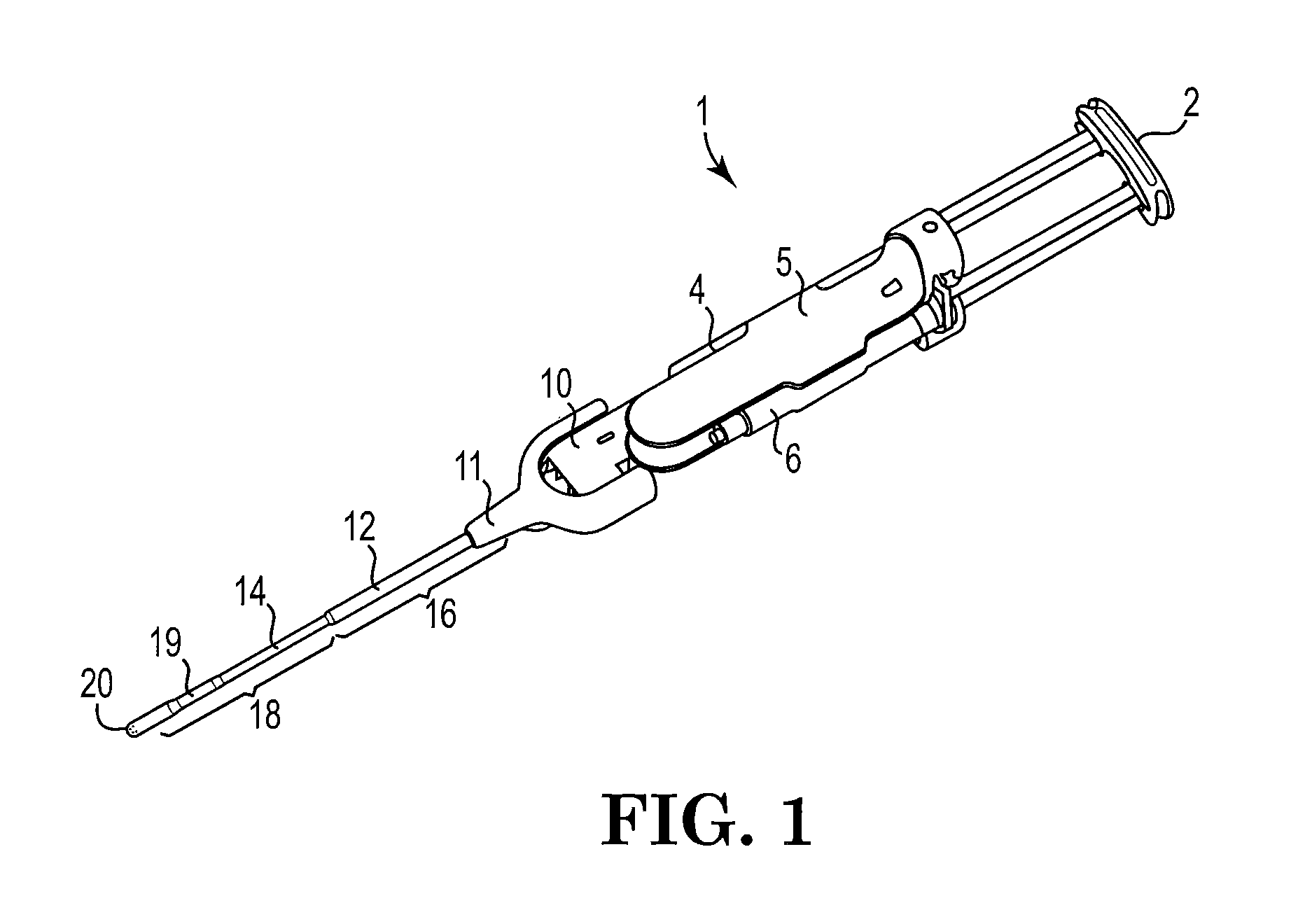
FIG. 1 is a perspective view of a spray head assembled onto a spray delivery system;
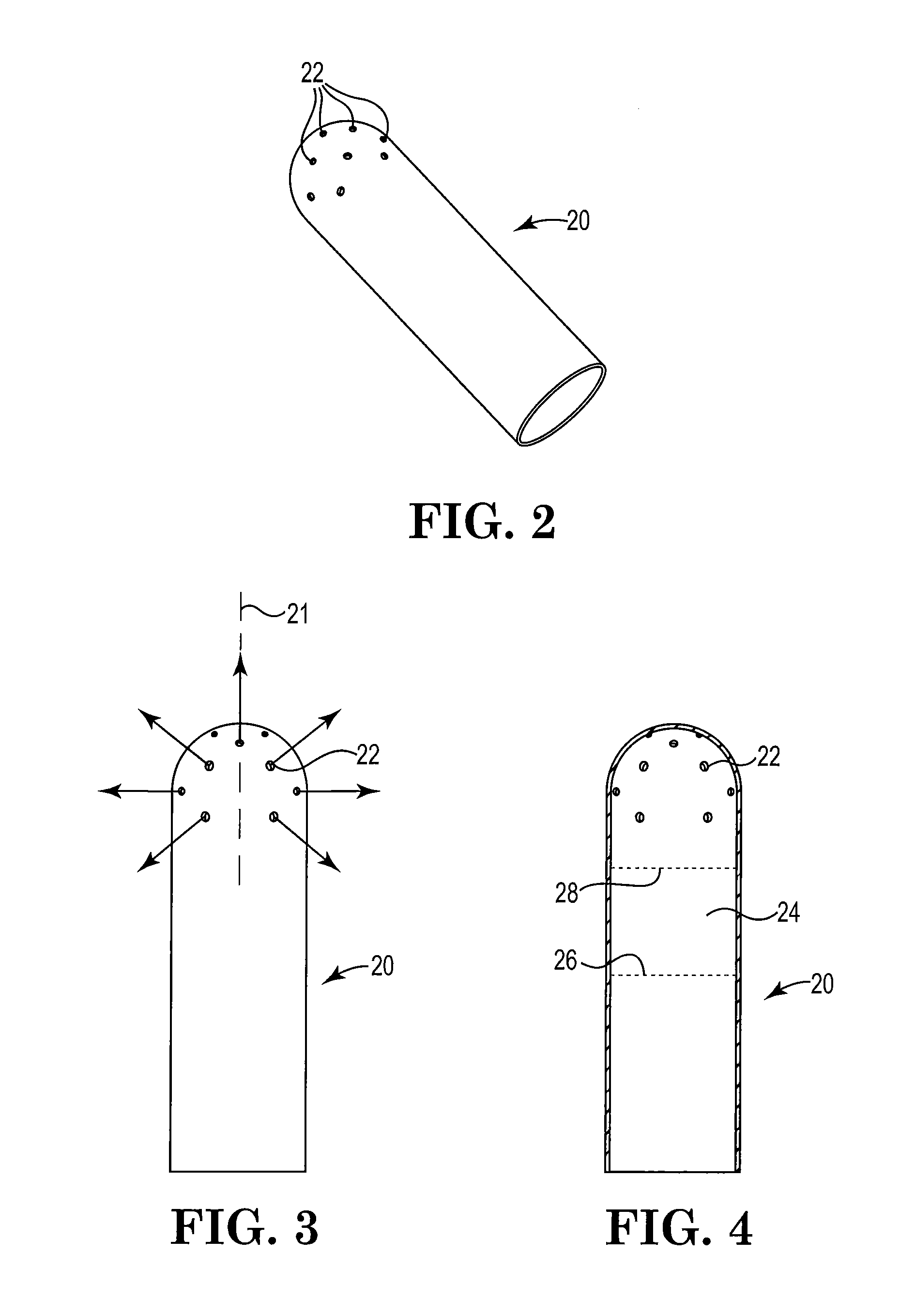
FIG. 2 is a perspective view of an exemplary spray head;
FIG. 3 is a plan view of the spray head of FIG. 2;
FIG. 4 is a cross sectional view of the spray head of FIG. 3;
FIG. 5 shows gel coverage maps obtained using the spray head of FIG. 2;
FIG. 6 is a perspective, exploded view of the spray delivery system of FIG. 1;
FIG. 7A is a perspective view of a distal portion of a cannula;
FIG. 7B is a perspective, exploded view of components in FIG. 7A;
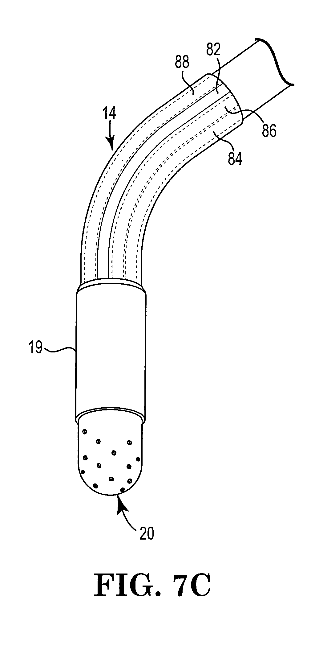
FIG. 7C is a perspective view of the FIG. 7A components after cannula 14 has been bent to a new shape; and
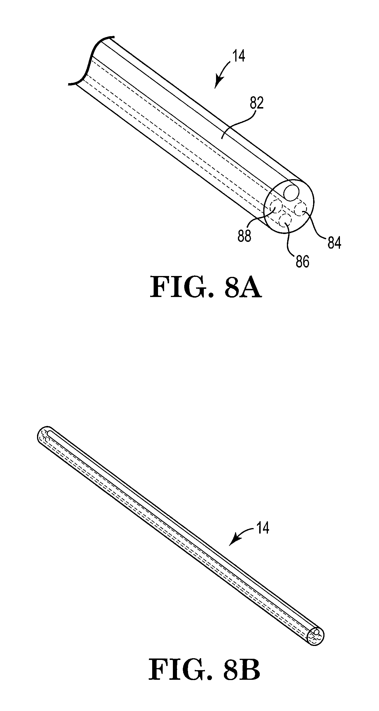
FIGS. 8A and 8B are perspective views, partially in phantom, of cannula 14 from FIG. 7A and FIG. 7B.
Like reference symbols in the various figures of the drawing indicate like elements. The elements in the drawing are not to scale.
DETAILED DESCRIPTION
The recitation of a numerical range using endpoints includes all numbers subsumed within that range (e.g., 1 to 5 includes 1, 1.5, 2, 2.75, 3, 3.80, 4, 5, etc.).
The present invention provides, in one aspect, a spray head and, in other aspects, a method of delivering tissue sealants using such spray head. FIG. 1, which shows an exemplary spray delivery system 1, in general, includes an actuating member 2, body 5 capable of receiving delivery devices (which in FIG. 1 are syringes 4, 6), a manifold 10 surrounded by a shroud 11, a support member 12, a cannula 14 which may be constrained at the proximal end portion 16 providing rigidity, and unconstrained at the distal end portion 18 providing flexibility, a sheath 19, and a spray head 20. The cannula 14 and spray head 20 are connected to body 5 through manifold 10. The manifold 10 engages body 5 and is connected to syringes 4, 6, and aids in dispensing fluid components stored in syringes 4, 6.
The spray head 20 is designed to include multiple openings at various angles and at various locations to enable material(s) entering the spray head 20 to exit in multiple directions. The spray head 20 may, for example, be used in a multi-component spray delivery system with a multi-lumen or multi-sectioned cannula as shown in FIG. 1 and as described in detail in U.S. patent application Ser. No. 13/284,600 and in U.S. patent application Ser. No. 13/284,387 (now U.S. Pat. No. 8,974,436 B2), respectively, both filed Oct. 28, 2011 and each of which is incorporated herein by reference in its entirety.
The spray head 20 may be used to apply compositions containing a variety of agents, such as multiple-component tissue sealant compositions, to a variety of bodily passageways or cavities including the nasal cavity (maxillary, frontal and sphenoid sinuses). Exemplary multi-component tissue sealants may include crosslinkable polysaccharide systems, for example, a first component containing chitosan or a chitosan derivative and a second component containing starch or a starch derivative. Other exemplary multi-component tissue sealants are provided in U.S. patent application Ser. No. 12/429,141, now published as U.S. Publication No. 2009/0270346 and U.S. patent application Ser. No. 12/429,150, now published as U.S. Publication No. 2009/0291912.
As shown in FIGS. 2 and 3, spray head 20 has multiple fluid spray outlet openings 22 at a variety of angles and at locations to permit fluid material(s) to exit in multiple directions. Although the distal end of spray head 20 may have a variety of shapes, spray head 20 desirably has a hemispherical shape with openings 22 desirably being arranged to provide a substantially hemispherical or suprahemispherical, substantially uniform spray pattern.
Depending on the spray coverage required, other opening arrangements beyond those shown in FIG. 2 are possible on spray head 20. The spray head 20 may have, for example, at least 10, at least 12, or at least 14 outlet openings and up to 32, up to 28 or up to 26 openings distributed at various planes separated by a distance of about 0.025 cm, 0.05 cm, or 0.075 cm over the distal end of spray head 20. This arrangement provides a larger spray coverage area as opposed to spray coverage from a single orifice or from orifices arranged in a single plane and minimizes a need to rotate or manipulate the spray head 20 once inserted into a passageway. The spray head openings 22 allow for spray coverage patterns over, for example, an arc extending at least 90 degrees, at least 135 degrees, or at least about 150 degrees from a central axis 21, as shown in FIG. 3.
FIG. 4 shows a cross sectional view of the spray head 20 with a space or region 24 as defined by 26, which defines the end of a lumen inserted in tip 20; and 28, which defines the distal end of space or region 24 which permits fluids exiting the lumen to mix before exiting spray head 20. The space or region 24, the mixing area may be, for example, from about 0.02 cm to 1.5 cm.
Spray head 20 may be made from a variety of materials, for example, stainless steel or other medically acceptable metal or alloy. Other materials suitable for spray head 20 include polyvinyl chloride (PVC), nylon, polyether ether ketone (PEEK), acrylonitrile butadiene styrene (ABS) and the like.
The spray head 20 desirably has a length enabling easy insertion and withdrawal of spray head 20 into an anatomical location. For example, for use in sinus cavities the spray head length preferably is about 5.0 mm to 20 mm, spray head wall thickness preferably is about 0.01 mm to 1.0 mm, more preferably about 0.2 mm; the spray head opening diameters preferably are about 0.01 mm to 3.0 mm, and the spray head outer diameter preferably is about 0.5 mm to 10 mm, more preferably 3-5 mm. The openings may, for example, be circular, round, oval or semi-circular in shape. The angle of the openings with respect to the spray head central axis 21 preferably is, for example, from about 0, 45, 90 and 120 degrees.
Cannula 14 may be a flexible or malleable member that may be assembled to include a rigid proximal end portion 16 and a malleable distal end portion 18. The rigid proximal end portion 16 may be constrained at the proximal end by support shaft 12 and shroud 11, which prevents or discourages cannula bending. The rigid proximal end portion 16 also includes the portion of cannula 14 surrounded by the support shaft 12. Cannula 14 may be bent at the malleable distal end portion 18, which extends from the end of the support shaft 12 up to the proximal portion of the spray head 20.
Cannula 14 and spray head 20 are connected to body 5 through manifold 10. Manifold 10 may be surrounded by a shroud 11 with support shaft 12 constraining the proximal end of cannula 14. Manifold 10 may be configured to receive portions of syringes 4, 6 without requiring threaded or rotating engagement of the syringe to manifold 10 to provide a liquid tight connection. Spray head 20 is connected to malleable distal end portion 18. Covering the interface between the malleable distal end portion 18 and spray head 20 is a sheath 19 which provides a smooth transitional interface at the joint between cannula 14 and spray head 20.
When used to deliver a tissue sealant to a sinus cavity, cannula 14 preferably has an overall length of about 10 cm to 15 cm, more preferably about 12 to 13 cm. The rigid proximal end portion 16 may have a length, in the range from about 4 cm to 8 cm, preferably about 5 cm to 7 cm, and the malleable distal end portion 18 may have a length, for example, in the range from about 4 cm to 8 cm, preferably about 5 cm to 7 cm. The outer diameter of cannula 14 may be from about 0.1 cm to 1.0 cm, preferably about 0.3 cm to 0.4 cm. The ratio of the rigid proximal end portion 16 to the malleable distal end portion 18 may be in a ratio of about 2:1 or about 1:2, and preferably about 1:1.
Depending on the specific cannula use, other dimensions are also acceptable. For example, cannula 14 may be used in laparoscopic anatomical or gynecological surgery, neural surgery, pulmonary surgery or the like.
The cannula 14 may be formed of a material acceptable for use inside the human body and of a selected durometer (hardness). The selected durometer aids in preventing the cannula from kinking when bent greater than 45 degrees, greater than 90 degrees or greater than 180 degrees with respect to a straight, unbent configuration. The selected material may include for example, thermoplastic or thermoset polymers such as polyolefins, silicones, polyvinyl chlorides, polyurethanes, polyesters and the like. To attain a desired durometer, fillers or plasticizers may be used. The amount and type of filler or plasticizer is determined by the selected thermoplastic or thermoset polymers used. Cannula 14 may have a durometer (Shore A) in the range, for example, from 60 to 95, preferably from about 85 to 95.
Referring to FIG. 2, support member 12 may be in the form of a cylindrical metal or plastic tube surrounding cannula 14 and molded within or otherwise connected to the distal end portion of shroud 11, for example, by adhesive or welding. The support member 12 preferably is made of stainless steel. Other exemplary materials include, for example, metals such aluminum and plastics such as thermoplastic or thermoset polymers. The support member 12 desirably has a thickness and length such that it minimizes physical obstruction during anatomic insertion and resists sideways deflection of proximal end portion 16 so as to provide improved control when maneuvering and navigating cannula 14 through bodily passageways. The support member 12 may, for example, have a thickness of about 0.01 cm to about 0.1 cm, preferably from about 0.02 cm to 0.03 cm; and a length, for example, of about 3 cm to 10 cm, preferably from about 4.5 cm to 5.5 cm.
As illustrated in FIG. 1 and FIG. 6, shroud or casing 11 surrounds outer portions of manifold 10. The shroud 11 also engages the support member 12, and when assembled to cannula 14, provides additional proximal rigidity to the cannula 14. Shroud 11 may be permanently attached to the manifold 10, for example, by adhesives, welding or injection molding or may be optionally removable.
As illustrated in FIG. 7A and FIG. 7B, sheath 19 may, for example, surround the proximal portion of spray head 20 and the distal end portion 18 producing a smooth interface between the spray head 20 and cannula 14. Sheath 19 also helps keep spray head 20 firmly attached to cannula 14 when withdrawing spray head 20 from a confined location.
Desirable lengths of sheath 19 may for example, range from about 10 mm to 50 mm, preferably from about 20 mm to 25 mm. A thickness for sheath 19 desirably may be selected such that it minimizes interference with anatomical features during cannula insertion. The sheath thickness may, for example, range from to 0.001 cm to 0.010 cm, preferably 0.001 cm to 0.003 cm. The sheath 19 may be a heat shrink tube, a mechanically expanded tube, or an extruded plastic tube, and may be made from a variety of materials, for example, polyester, polyolefin, and fluoropolymers.
As shown in FIG. 8A and FIG. 8B, an exemplary cannula 14 may enclose multiple lumens that extend the entire cannula length, from the rigid proximal end portion 16 to the malleable distal end portion 18 and maintains the separation of each lumen. The individual lumen diameters are dependent on a number of factors, including the spray head opening diameters, the desired pressure and flow rate. The lumens may, for example, all be of the same diameter and cross sectional shape. The lumen shape may be, for example, circular, oval, square or D-shaped in cross-section, with the flat portions of neighboring D-shapes being adjacent to one another.
As illustrated in FIG. 8A, at least one of the lumens may include a reinforcement member 82 to allow selective bending of the cannula 14 to fit different orientations. The reinforcement member 82 may, for example, be in the form of a wire located within and extending along the length of a lumen. The reinforcement member 82 may, but need not be centrally located in the multi-lumen cannula 14. In such embodiments, the cannula 14 may be formed with at least two lumens, one of which will become occupied by the reinforcement member 82. The cannula 14 may also be formed by extruding or molding it over the reinforcement member 82 and by providing at least one lumen through which fluid may flow.
The reinforcement member 82 may be made of, for example, metal or a metal alloy such as stainless steel, copper, aluminum or the like. In other examples, reinforcement member 82 may be made of a shape memory metal such as Nitinol. The diameter of the reinforcement member 82, may, for example, range from 0.001 cm to 0.10 cm, preferably 0.03 cm to 0.05 cm. The shape of the reinforcement member 82 may be, for example, circular, oval, square or D-shaped in cross-section. The stiffness of the reinforcement member 82 may be full hard, half hard, quarter hard, annealed, soft or any other desired stiffness depending on the desired application.
The cannula 14, illustrated in FIG. 8A and FIG. 8B, includes four lumens, one of which is occupied by reinforcement member 82. Remaining lumens 84, 86, 88 are in fluid communication with one or more fluid supplies such as syringes 4, 6 and a source of pressurized air (not shown) that may be introduced into lumen 88 via port 30, which is shown in FIG. 6.
In one exemplary assembly process for the disclosed device, an operator first inserts the actuating member 2 into body 5. Alternatively, actuating member 2 may be preassembled with body 5. Syringes 4, 6 are positioned against body 5 and actuating member 2 so that body 5 and actuating member 2 can receive and capture syringes 4, 6. In this manner, syringes 4, 6 are held substantially parallel in body 5.
Once the syringes are received and captured by body 5, cannula 14 and spray head 20 are assembled to body 5 through manifold 10. Cannula 14 and spray head 20 may if desired be preassembled to manifold 10 during manufacturing.
The operator then connects manifold 10 to syringe outlets to provide an unthreaded, liquid-tight connection such that the syringe contents in syringe barrels are in fluid communication with cannula 14 through manifold 10.
When the delivery device 1 is fully assembled, the operator shapes the cannula 14 to a desired shape. Cannula 14 desirably is sufficiently stiff so that it will retain its shape until bent into a new shape. The shaped cannula 14 and spray head 20 are then maneuvered or navigated into a desired treatment site within the patient's body, for example, a nasal or sinus cavity or other opening, recess or passageway. Once satisfactorily positioned, an operator may, for example, depress actuating member 2 to move the plunger of syringe 4, 6 toward the syringe outlets, advancing the fluid syringe contents substantially at the same time through the separate syringe barrels and out into respective fluid channels in manifold 10 which maintain the fluid separation. Continued force will advance the fluids through the multi-lumen cannula 14 and into a region within spray head 20 where they mix before the mixed fluids exit spray head 20. If compressed gas is used, it may be supplied through port 30. The gas stream passes through a lumen of multi-lumen cannula 14 into the mixing region of spray head 20. The gas stream helps atomize the mixed syringe contents resulting in much smaller droplets. Overall, a smoother manipulation and easier control of the device through passageways is provided.
The invention is further illustrated in the following non-limiting examples.
Example 1
A spray head like that shown in FIGS. 2 and 3 was prepared with an outer diameter of 4 mm and having 26 openings. The openings were arranged at 5 different planes and five different angles along the length of the spray head hemisphere. The first set of 4 openings on the first plane (starting from the distal end) was 30 degrees from the central axis. The second set of 4 openings on the second plane was 45 degrees from the central axis. The third set of 6 openings on the third plane was 67.5 degrees from the central axis. And the fourth and fifth sets of 6 openings on the fourth and fifth plane each were 90 degrees from the central axis. All openings were symmetrically located along the diameter of the spray head. The diameter for all 26 openings was 0.0254 cm. The wall thickness of the spray head was 0.0254 cm. The spray head was assembled onto a delivery device and the spray coverage was measured as follows. A 1.5 cm (0.6 inches) portion of the spray head was inserted into the center of a uniform spherical plastic test chamber and approximately 2 ml total (1.0 ml per syringe) of a mixture of carboxymethyl chitosan and starch was sprayed into the test chamber by depressing the plunger in a steady motion. A 50 psi air source was supplied to the spray head to assist in biomaterial delivery. The sprayed material was allowed to crosslink for one minute after which the spherical test chamber was opened and the gel coverage area on the top half of the sphere was observed and recorded.
Examples of spray coverage data are shown in FIG. 5. The coverage maps are representative of spherical test data laid out on a 2D flat surface like a map with the central (0,0) point indicating the central spray head location. The black regions indicate complete gel coverage and the white regions (gaps) indicate no gel coverage. A 100% coverage rating was taken to be coverage over at least a 270.degree. arc, or coverage over at least a 135.degree. arc on either side of central axis 21.
Example 2
Using the experimental set up described in Example 1, gel thickness was also measured. Using a 3 mm wide blade, portions of the crosslinked gel on the top half of the sphere were scraped to create a "test area" or "valley." Using a Keyence microscope the gel thickness was determined on either side of the test area and recorded as shown below.
Each test was conducted five times. Two measurements were taken per test one from the left and one from the right side of the test area.
TABLE-US-00001 TABLE 1 Gel Coverage Area Thickness Variability Measure Experiment # L-Side Thickness (in) R-Side Thickness (in) 1 0.0083 0.0063 2 0.0084 0.006 3 0.009 0.0086 4 0.0066 0.0070 5 0.0054 0.0071 0.0075 .+-. 0.0015 0.007 0.001
The gel coverage on either side of the test area showed a difference of 0.0005 inches (<10%). In other words, the gel thickness showed only a 2 fold difference from one side to the other side of the test area, indicating consistent, uniform gel coverage.
* * * * *
D00000
D00001
D00002
D00003
D00004
D00005
D00006
XML
uspto.report is an independent third-party trademark research tool that is not affiliated, endorsed, or sponsored by the United States Patent and Trademark Office (USPTO) or any other governmental organization. The information provided by uspto.report is based on publicly available data at the time of writing and is intended for informational purposes only.
While we strive to provide accurate and up-to-date information, we do not guarantee the accuracy, completeness, reliability, or suitability of the information displayed on this site. The use of this site is at your own risk. Any reliance you place on such information is therefore strictly at your own risk.
All official trademark data, including owner information, should be verified by visiting the official USPTO website at www.uspto.gov. This site is not intended to replace professional legal advice and should not be used as a substitute for consulting with a legal professional who is knowledgeable about trademark law.