Recover storage array using remote deduplication device
Cohen , et al. O
U.S. patent number 10,437,783 [Application Number 14/496,790] was granted by the patent office on 2019-10-08 for recover storage array using remote deduplication device. This patent grant is currently assigned to EMC IP Holding Company LLC. The grantee listed for this patent is EMC Corporation. Invention is credited to Saar Cohen, Assaf Natanzon.


View All Diagrams
| United States Patent | 10,437,783 |
| Cohen , et al. | October 8, 2019 |
Recover storage array using remote deduplication device
Abstract
In one aspect, a method includes extracting configuration files from a deduplication device, configuring a storage array based on the configuration files extracted, extracting data for a point-in-time (PIT) from the deduplication device and sending the data for the PIT extracted to the storage array. In another aspect, an apparatus includes electronic hardware circuitry configured to extract configuration files from a deduplication device, configure a storage array based on the configuration files extracted, extract data for a PIT from the deduplication device and send the data for the PIT extracted to the storage array. In a further aspect, an article includes a non-transitory computer-readable medium that stores computer-executable instructions. The instructions cause a machine to extract configuration files from a deduplication device, configure a storage array based on the configuration files extracted, extract data for a PIT from the deduplication device and send the data for the PIT extracted to the storage array.
| Inventors: | Cohen; Saar (Moshav Mishmeret, IL), Natanzon; Assaf (Tel Aviv, IL) | ||||||||||
|---|---|---|---|---|---|---|---|---|---|---|---|
| Applicant: |
|
||||||||||
| Assignee: | EMC IP Holding Company LLC
(Hopkinton, MA) |
||||||||||
| Family ID: | 68102016 | ||||||||||
| Appl. No.: | 14/496,790 | ||||||||||
| Filed: | September 25, 2014 |
| Current U.S. Class: | 1/1 |
| Current CPC Class: | G06F 11/1461 (20130101); G06F 16/2365 (20190101); G06F 11/1448 (20130101); G06F 16/1748 (20190101); G06F 11/1458 (20130101); G06F 2201/84 (20130101); G06F 11/1453 (20130101) |
| Current International Class: | G06F 16/174 (20190101); G06F 16/23 (20190101); G06F 11/14 (20060101) |
References Cited [Referenced By]
U.S. Patent Documents
| 5170480 | December 1992 | Mohan et al. |
| 5249053 | September 1993 | Jain |
| 5388254 | February 1995 | Betz et al. |
| 5499367 | March 1996 | Bamford et al. |
| 5526397 | June 1996 | Lohman |
| 5864837 | January 1999 | Maimone |
| 5990899 | January 1999 | Whitten |
| 5879459 | March 1999 | Gadgil et al. |
| 6042652 | March 2000 | Hyun et al. |
| 6065018 | May 2000 | Beier et al. |
| 6143659 | November 2000 | Leem |
| 6148340 | November 2000 | Bittinger et al. |
| 6174377 | January 2001 | Doering et al. |
| 6174809 | January 2001 | Kang et al. |
| 6203613 | March 2001 | Gates et al. |
| 6260125 | July 2001 | McDowell |
| 6270572 | August 2001 | Kim et al. |
| 6272534 | August 2001 | Guha |
| 6287965 | September 2001 | Kang et al. |
| 6467023 | October 2002 | DeKoning et al. |
| 6574657 | June 2003 | Dickinson |
| 6621493 | September 2003 | Whitten |
| 6804676 | October 2004 | Bains, II |
| 6947981 | September 2005 | Lubbers et al. |
| 7051126 | March 2006 | Franklin |
| 7043610 | May 2006 | Horn et al. |
| 7076620 | July 2006 | Takeda et al. |
| 7111197 | September 2006 | Kingsbury et al. |
| 7117327 | October 2006 | Hirakawa et al. |
| 7120768 | October 2006 | Mizuno et al. |
| 7130975 | October 2006 | Suishu et al. |
| 7139927 | November 2006 | Park et al. |
| 7159088 | January 2007 | Hirakawa et al. |
| 7167963 | January 2007 | Hirakawa et al. |
| 7203741 | April 2007 | Marco et al. |
| 7222136 | May 2007 | Brown et al. |
| 7296008 | November 2007 | Passerini et al. |
| 7313719 | December 2007 | Elahee |
| 7328373 | February 2008 | Kawamura et al. |
| 7353335 | April 2008 | Kawamura |
| 7360113 | April 2008 | Anderson et al. |
| 7426618 | September 2008 | Vu et al. |
| 7516287 | April 2009 | Ahal et al. |
| 7519625 | April 2009 | Honami et al. |
| 7519628 | April 2009 | Leverett |
| 7546485 | June 2009 | Cochran et al. |
| 7577867 | August 2009 | Lewin et al. |
| 7590887 | September 2009 | Kano |
| 7606940 | October 2009 | Yamagami |
| 7627612 | December 2009 | Ahal et al. |
| 7627687 | December 2009 | Ahal et al. |
| 7669020 | February 2010 | Shah |
| 7719443 | May 2010 | Natanzon |
| 7757057 | July 2010 | Sangapu et al. |
| 7774565 | August 2010 | Lewin et al. |
| 7797358 | September 2010 | Ahal et al. |
| 7840536 | November 2010 | Ahal et al. |
| 7840662 | November 2010 | Natanzon |
| 7844856 | November 2010 | Ahal et al. |
| 7849361 | December 2010 | Ahal et al. |
| 7860836 | December 2010 | Natanzon et al. |
| 7882286 | February 2011 | Natanzon et al. |
| 7934262 | April 2011 | Natanzon et al. |
| 7958372 | June 2011 | Natenzon |
| 8037162 | October 2011 | Marco et al. |
| 8041940 | October 2011 | Natanzon et al. |
| 8060713 | November 2011 | Natanzon |
| 8060714 | November 2011 | Natanzon |
| 8103937 | January 2012 | Natanzon et al. |
| 8108634 | January 2012 | Natanzon et al. |
| 8205009 | June 2012 | Heller et al. |
| 8214612 | July 2012 | Natanzon |
| 8250149 | August 2012 | Marco et al. |
| 8271441 | September 2012 | Natanzon et al. |
| 8271447 | September 2012 | Natanzon et al. |
| 8332687 | December 2012 | Natanzon et al. |
| 8335761 | December 2012 | Natanzon |
| 8335771 | December 2012 | Natanzon et al. |
| 8341115 | December 2012 | Natanzon et al. |
| 8370648 | February 2013 | Natanzon |
| 8380885 | February 2013 | Natanzon |
| 8392680 | March 2013 | Natanzon et al. |
| 8429362 | April 2013 | Natanzon et al. |
| 8433869 | April 2013 | Natanzon et al. |
| 8438135 | May 2013 | Natanzon et al. |
| 8464101 | June 2013 | Natanzon et al. |
| 8478955 | July 2013 | Natanzon et al. |
| 8495304 | July 2013 | Natanzon et al. |
| 8510279 | August 2013 | Natanzon et al. |
| 8521691 | August 2013 | Natanzon |
| 8521694 | August 2013 | Natanzon |
| 8543609 | September 2013 | Natanzon |
| 8583885 | November 2013 | Natanzon |
| 8600945 | December 2013 | Natanzon et al. |
| 8601085 | December 2013 | Ives et al. |
| 8627012 | January 2014 | Derbeko et al. |
| 8683592 | March 2014 | Dotan et al. |
| 8694700 | April 2014 | Natanzon et al. |
| 8706700 | April 2014 | Natanzon et al. |
| 8712962 | April 2014 | Natanzon et al. |
| 8719497 | May 2014 | Don et al. |
| 8725691 | May 2014 | Natanzon |
| 8725692 | May 2014 | Natanzon et al. |
| 8726066 | May 2014 | Natanzon et al. |
| 8738813 | May 2014 | Natanzon et al. |
| 8745004 | June 2014 | Natanzon et al. |
| 8751828 | June 2014 | Raizen et al. |
| 8769336 | July 2014 | Natanzon et al. |
| 8805786 | August 2014 | Natanzon |
| 8806161 | August 2014 | Natanzon |
| 8825848 | September 2014 | Dotan et al. |
| 8832399 | September 2014 | Natanzon et al. |
| 8850143 | September 2014 | Natanzon |
| 8850144 | September 2014 | Natanzon et al. |
| 8862546 | October 2014 | Natanzon et al. |
| 8892835 | November 2014 | Natanzon et al. |
| 8898112 | November 2014 | Natanzon et al. |
| 8898409 | November 2014 | Natanzon et al. |
| 8898515 | November 2014 | Natanzon |
| 8898519 | November 2014 | Natanzon et al. |
| 8914595 | December 2014 | Natanzon |
| 8924668 | December 2014 | Natanzon |
| 8930500 | January 2015 | Marco et al. |
| 8930947 | January 2015 | Derbeko et al. |
| 8977593 | March 2015 | Natanzon et al. |
| 8977826 | March 2015 | Meiri et al. |
| 8996460 | March 2015 | Frank et al. |
| 8996461 | March 2015 | Natanzon et al. |
| 8996827 | March 2015 | Natanzon |
| 9003138 | April 2015 | Natanzon et al. |
| 9026696 | May 2015 | Natanzon et al. |
| 9031913 | May 2015 | Natanzon |
| 9032160 | May 2015 | Natanzon et al. |
| 9037818 | May 2015 | Natanzon et al. |
| 9063994 | June 2015 | Natanzon et al. |
| 9069479 | June 2015 | Natanzon |
| 9069709 | June 2015 | Natanzon et al. |
| 9081754 | July 2015 | Natanzon et al. |
| 9081842 | July 2015 | Natanzon et al. |
| 9087008 | July 2015 | Natanzon |
| 9087112 | July 2015 | Natanzon et al. |
| 9104529 | August 2015 | Derbeko et al. |
| 9110914 | August 2015 | Frank et al. |
| 9116811 | August 2015 | Derbeko et al. |
| 9128628 | September 2015 | Natanzon et al. |
| 9128855 | September 2015 | Natanzon et al. |
| 9134914 | September 2015 | Derbeko et al. |
| 9135119 | September 2015 | Natanzon et al. |
| 9135120 | September 2015 | Natanzon |
| 9146878 | September 2015 | Cohen et al. |
| 9152339 | October 2015 | Cohen et al. |
| 9152578 | October 2015 | Saad et al. |
| 9152814 | October 2015 | Natanzon |
| 9158578 | October 2015 | Derbeko et al. |
| 9158630 | October 2015 | Natanzon |
| 9160526 | October 2015 | Raizen et al. |
| 9177670 | November 2015 | Derbeko et al. |
| 9189339 | November 2015 | Cohen et al. |
| 9189341 | November 2015 | Natanzon et al. |
| 9201736 | December 2015 | Moore et al. |
| 9223659 | December 2015 | Natanzon et al. |
| 9225529 | December 2015 | Natanzon et al. |
| 9235481 | January 2016 | Natanzon et al. |
| 9235524 | January 2016 | Derbeko et al. |
| 9235632 | January 2016 | Natanzon |
| 9244997 | January 2016 | Natanzon et al. |
| 9256605 | February 2016 | Natanzon |
| 9274718 | March 2016 | Natanzon et al. |
| 9275063 | March 2016 | Natanzon |
| 9286052 | March 2016 | Solan et al. |
| 9305009 | April 2016 | Bono et al. |
| 9323750 | April 2016 | Natanzon et al. |
| 9330155 | May 2016 | Bono et al. |
| 9336094 | May 2016 | Wolfson et al. |
| 9336230 | May 2016 | Natanzon |
| 9367260 | June 2016 | Natanzon |
| 9378096 | June 2016 | Erel et al. |
| 9378219 | June 2016 | Bono et al. |
| 9378261 | June 2016 | Bono et al. |
| 9383937 | July 2016 | Frank et al. |
| 9389800 | July 2016 | Natanzon et al. |
| 9405481 | August 2016 | Cohen et al. |
| 9405684 | August 2016 | Derbeko et al. |
| 9405765 | August 2016 | Natanzon |
| 9411535 | August 2016 | Shemer et al. |
| 9459804 | October 2016 | Natanzon et al. |
| 9460028 | October 2016 | Raizen et al. |
| 9471579 | October 2016 | Natanzon |
| 9477407 | October 2016 | Marshak et al. |
| 9501542 | November 2016 | Natanzon |
| 9507732 | November 2016 | Natanzon et al. |
| 9507845 | November 2016 | Natanzon et al. |
| 9514138 | December 2016 | Natanzon et al. |
| 9524218 | December 2016 | Veprinsky et al. |
| 9529885 | December 2016 | Natanzon et al. |
| 9535800 | January 2017 | Natanzon et al. |
| 9535801 | January 2017 | Natanzon et al. |
| 9547459 | January 2017 | BenHanokh et al. |
| 9547591 | January 2017 | Natanzon et al. |
| 9552405 | January 2017 | Moore et al. |
| 9557921 | January 2017 | Cohen et al. |
| 9557925 | January 2017 | Natanzon |
| 9563517 | February 2017 | Natanzon et al. |
| 9563684 | February 2017 | Natanzon et al. |
| 9575851 | February 2017 | Natanzon et al. |
| 9575857 | February 2017 | Natanzon |
| 9575894 | February 2017 | Natanzon et al. |
| 9582382 | February 2017 | Natanzon et al. |
| 9588703 | March 2017 | Natanzon et al. |
| 9588847 | March 2017 | Natanzon et al. |
| 9594822 | March 2017 | Natanzon et al. |
| 9600377 | March 2017 | Cohen et al. |
| 9619255 | April 2017 | Natanzon |
| 9619256 | April 2017 | Natanzon et al. |
| 9619264 | April 2017 | Natanzon et al. |
| 9619543 | April 2017 | Natanzon et al. |
| 9632881 | April 2017 | Natanzon |
| 9639295 | May 2017 | Natanzon et al. |
| 9639383 | May 2017 | Natanzon |
| 9639592 | May 2017 | Natanzon et al. |
| 9652333 | May 2017 | Bournival et al. |
| 9658929 | May 2017 | Natanzon et al. |
| 9659074 | May 2017 | Natanzon et al. |
| 9665305 | May 2017 | Natanzon et al. |
| 9668704 | June 2017 | Fuimaono et al. |
| 9672117 | June 2017 | Natanzon et al. |
| 9678680 | June 2017 | Natanzon et al. |
| 9678728 | June 2017 | Shemer et al. |
| 9684576 | June 2017 | Natanzon et al. |
| 9690504 | June 2017 | Natanzon et al. |
| 9696939 | July 2017 | Frank et al. |
| 9710177 | July 2017 | Natanzon |
| 9720618 | August 2017 | Panidis et al. |
| 9722788 | August 2017 | Natanzon et al. |
| 9727429 | August 2017 | Moore et al. |
| 9733969 | August 2017 | Derbeko et al. |
| 9737111 | August 2017 | Lustik |
| 9740572 | August 2017 | Natanzon et al. |
| 9740573 | August 2017 | Natanzon |
| 9740880 | August 2017 | Natanzon et al. |
| 9749300 | August 2017 | Cale et al. |
| 9772789 | September 2017 | Natanzon et al. |
| 9798472 | October 2017 | Natanzon et al. |
| 9798490 | October 2017 | Natanzon |
| 9804934 | October 2017 | Natanzon et al. |
| 9811431 | November 2017 | Natanzon et al. |
| 9823865 | November 2017 | Natanzon et al. |
| 9823973 | November 2017 | Natanzon |
| 9832261 | November 2017 | Don et al. |
| 9846698 | December 2017 | Panidis et al. |
| 9875042 | January 2018 | Natanzon et al. |
| 9875162 | January 2018 | Panidis et al. |
| 9880777 | January 2018 | Bono et al. |
| 9881014 | January 2018 | Bono et al. |
| 9910620 | March 2018 | Veprinsky et al. |
| 9910621 | March 2018 | Golan et al. |
| 9910735 | March 2018 | Natanzon |
| 9910739 | March 2018 | Natanzon et al. |
| 9917854 | March 2018 | Natanzon et al. |
| 9921955 | March 2018 | Derbeko et al. |
| 9933957 | April 2018 | Cohen et al. |
| 9934302 | April 2018 | Cohen et al. |
| 9940205 | April 2018 | Natanzon |
| 9940460 | April 2018 | Derbeko et al. |
| 9946649 | April 2018 | Natanzon et al. |
| 9959061 | May 2018 | Natanzon et al. |
| 9965306 | May 2018 | Natanzon et al. |
| 9990256 | June 2018 | Natanzon |
| 9996539 | June 2018 | Natanzon |
| 10007626 | June 2018 | Saad et al. |
| 10019194 | July 2018 | Baruch et al. |
| 10025931 | July 2018 | Natanzon et al. |
| 10031675 | July 2018 | Veprinsky et al. |
| 10031690 | July 2018 | Panidis et al. |
| 10031692 | July 2018 | Elron et al. |
| 10031703 | July 2018 | Natanzon et al. |
| 10037251 | July 2018 | Bono et al. |
| 10042579 | August 2018 | Natanzon |
| 10042751 | August 2018 | Veprinsky et al. |
| 10055146 | August 2018 | Natanzon et al. |
| 10055148 | August 2018 | Natanzon et al. |
| 10061666 | August 2018 | Natanzon et al. |
| 10067694 | September 2018 | Natanzon et al. |
| 10067837 | September 2018 | Natanzon et al. |
| 2002/0129168 | September 2002 | Kanai et al. |
| 2003/0048842 | March 2003 | Fourquin et al. |
| 2003/0061537 | March 2003 | Cha et al. |
| 2003/0110278 | June 2003 | Anderson |
| 2003/0145317 | July 2003 | Chamberlain |
| 2003/0195864 | October 2003 | Vishlitzky |
| 2003/0196147 | October 2003 | Hirata et al. |
| 2004/0205092 | October 2004 | Longo et al. |
| 2004/0250032 | December 2004 | Ji et al. |
| 2004/0254964 | December 2004 | Kodama et al. |
| 2004/0268067 | December 2004 | Yamagami |
| 2005/0015663 | January 2005 | Armangau et al. |
| 2005/0028022 | February 2005 | Amano |
| 2005/0049924 | March 2005 | DeBettencourt et al. |
| 2005/0172092 | August 2005 | Lam et al. |
| 2005/0182953 | August 2005 | Stager |
| 2005/0273655 | December 2005 | Chow et al. |
| 2006/0031647 | February 2006 | Hirakawa et al. |
| 2006/0047996 | March 2006 | Anderson et al. |
| 2006/0064416 | March 2006 | Sim-Tang |
| 2006/0107007 | May 2006 | Hirakawa et al. |
| 2006/0117211 | June 2006 | Matsunami et al. |
| 2006/0161810 | July 2006 | Bao |
| 2006/0179343 | August 2006 | Kitamura |
| 2006/0195670 | August 2006 | Iwamura et al. |
| 2006/0212462 | September 2006 | Hellen et al. |
| 2007/0055833 | March 2007 | Vu et al. |
| 2007/0162513 | July 2007 | Lewin et al. |
| 2007/0180304 | August 2007 | Kano |
| 2007/0198602 | August 2007 | Ngo et al. |
| 2007/0198791 | August 2007 | Iwamura et al. |
| 2007/0220309 | September 2007 | Andre |
| 2007/0220311 | September 2007 | Lewin et al. |
| 2007/0266053 | November 2007 | Ahal et al. |
| 2008/0082591 | April 2008 | Ahal et al. |
| 2008/0082592 | April 2008 | Ahal et al. |
| 2008/0082770 | April 2008 | Ahal et al. |
| 2008/0201391 | August 2008 | Arakawa |
| 2009/0307285 | December 2009 | Gipp |
| 2010/0070725 | March 2010 | Prahlad |
| 2014/0337562 | November 2014 | Long |
| 2016/0077919 | March 2016 | Duggan |
| 1154356 | Nov 2001 | EP | |||
| WO 00 45581 | Aug 2000 | WO | |||
Other References
|
Gibson, "Five Point Plan Lies at the Heart of Compression Technology;" Apr. 29, 1991; p. 1. cited by applicant . Soules, "Metadata Efficiency in Versioning File Systems;" 2003; pp. 1-16. cited by applicant . AIX System Management Concepts: Operating Systems and Devices; May 2000; pp. 1-280. cited by applicant . Soules et al.; "Metadata Efficiency in a Comprehensive Versioning File System;" May 2002; CMU-CS-02-145; School of Computer Science, Carnegie Mellon University, Pittsburgh, PA 15213; 33 pages. cited by applicant . Linux Filesystems; Sams Publishing; 2002; pp. 17-22 and 67-71. cited by applicant . Bunyan, "Multiplexing in a BrightStor.RTM. ARCserve.RTM. Backup Release 11;" Mar. 2004; pp. 1-4. cited by applicant . Marks, "Network Computing;" Feb. 2, 2006; pp. 1-8. cited by applicant . Hill, "Network Computing;" Jun. 8, 2006; pp. 1-9. cited by applicant . Microsoft Computer Dictionary; 2002; Press Fifth Edition; 2 pages. cited by applicant . Retrieved from http://en.wikipedia.org/wiki/DEFLATE; Deflate; Jun. 19, 2008; pp. 1-6. cited by applicant . Retrieved from http://en.wikipedia.org/wiki/Huffman_coding; Huffman Coding; Jun. 8, 2008; pp. 1-11. cited by applicant . Retrieved from http:///en.wikipedia.org/wiki/LZ77; LZ77 and LZ78; Jun. 17, 2008; pp. 1-2. cited by applicant . U.S. Appl. No. 11/609,560. cited by applicant . U.S. Appl. No. 12/057,652. cited by applicant . U.S. Appl. No. 11/609,561. cited by applicant . U.S. Appl. No. 11/356,920. cited by applicant . U.S. Appl. No. 10/512,687. cited by applicant . U.S. Appl. No. 11/536,233. cited by applicant . U.S. Appl. No. 11/536,215. cited by applicant . U.S. Appl. No. 11/536,160. cited by applicant . U.S. Appl. No. 11/964,168. cited by applicant. |
Primary Examiner: Trujillo; James
Assistant Examiner: Morris; John J
Attorney, Agent or Firm: Daly, Crowley Mofford & Durkee, LLP
Claims
What is claimed is:
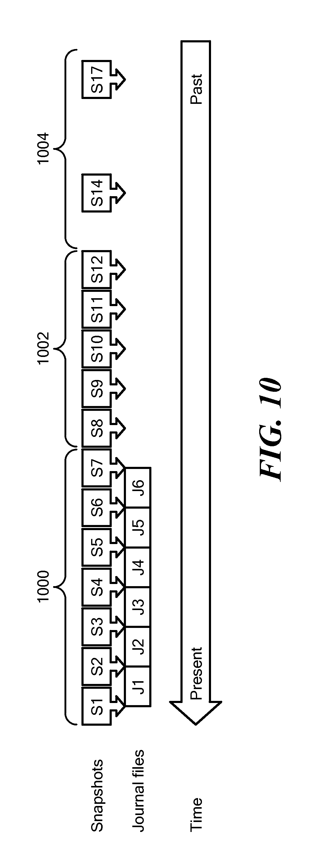
1. A method comprising: extracting configuration files from a deduplication device, the configuration files comprising configuration data used to reconstruct a storage array, the configuration data comprising volume IDs of volumes on the storage array, sizes of the volumes and consistency group data, the consistency group data comprising a list of consistency groups protected in the deduplication storage and a list of the devices of each consistency group; configuring the storage array based on the configuration files extracted, comprising: setting up logical units; setting up volumes for each logical unit; configuring hosts to access the logical units; and configuring a data protection appliance with a consistency group mapping between snapshots and journal files, wherein the snapshots include a file of a snapshot of at least one of the logical units for different points-in-time, and, wherein the journal files include differences between first and second ones of the snapshots of that at least one of the logical units; extracting data for a point-in-time (PIT) from the deduplication device, wherein the PIT is between selected ones of the snapshots, the method further comprising: identifying a snapshot of the selected ones of the snapshots that is nearest the PIT; identifying an input/output (I/O) received before the PIT and after the snapshot nearest the PIT; accessing one of the journal files and identifying a journal entry nearest the PIT; generating an interim snapshot including unchanged data from the snapshot nearest the PIT and data retrieved from the one of the journal files; sending data for the point-in-time to the storage array, the data for the PIT including the interim snapshot; and configuring a backup policy for each of the journal files and the snapshots, the backup policy defining backup windows indicating intervals of time that designate which of the journal files and snapshots will be retained in storage and a corresponding interval of time to be stored, each of the backup windows specifying varying granularities with respect to the intervals of time, wherein each of the journal files and the snapshots are stored for a time period corresponding to a designated one of the backup windows; wherein the backup windows include a short-term protection window, a mid-term protection window, and a long-term protection window; wherein the short-term protection window is configured to protect snapshots and journal files allowing for point-in-time recovery; wherein the mid-term protection window includes only snapshot files for the corresponding time interval; and wherein the journal files and snapshots move from the short-term protection window to the long-term protection window when a time interval defined for a respective one of the windows expires.
2. The method of claim 1, further comprising: notifying a user point-in-time available to recover; and receiving from the user the point-in-time to recover.
3. The method of claim 1, wherein the deduplication device is a first deduplication device, and further comprising backing up a second deduplication device to the first deduplication device.
4. The method of claim 2, wherein the storage array is a first storage array, and further comprising backing up a second storage array to the second deduplication device.
5. The method of claim 1, wherein extracting configuration files from a deduplication device comprises extracting configuration files from a deduplication device using a data protection appliance, and wherein configuring a storage array based on the configuration files extracted comprises configuring a storage array based on the configuration files extracted using the data protection appliance.
6. The method of claim 1, wherein the extracting configuration files, configuring the storage array, and configuring the data protection appliance is performed at a replication site, wherein in response to a recovery operation, the data protection appliance at the replication site extracts the data for the PIT, generates the interim snapshot, and sends the data for the PIT to the storage array, the storage array configured at the replication site.
7. The method of claim 6, further comprising backing up the configuration files, the snapshots, the journal files, and the consistency group mapping between the snapshots and journal files from a production site to the replication site prior to the recovery operation.
8. An apparatus, comprising: electronic hardware circuitry configured to: extract configuration files from a deduplication device, the configuration files comprising configuration data used to reconstruct a storage array, the configuration data comprising volume IDs of volumes on the storage array, sizes of the volumes and consistency group data, the consistency group data comprising a list of consistency groups protected in the deduplication storage and a list of the devices of each consistency group; configure the storage array based on the configuration files extracted comprising: setting up logical units; setting up volumes for each logical unit; configuring hosts to access the logical units; and configuring a data protection appliance with a consistency group mapping between snapshots and journal files, wherein the snapshots include a file of a snapshot of at least one of the logical units for different points-in-time, and, wherein the journal files include differences between first and second ones of the snapshots of that at least one of the logical units; extract data for a point-in-time (PIT) from the deduplication device, wherein the PIT is between selected ones of the snapshots, the electronic hardware circuitry further configured to: identify a snapshot of the selected ones of the snapshots that is nearest the PIT; identify an input/output (I/O) received before the PIT and after the snapshot nearest the PIT; access one of the journal files and identifying a journal entry nearest the PIT; generate an interim snapshot including unchanged data from the snapshot nearest the PIT and data retrieved from the one of the journal files; and send data for the point-in-time to the storage array, the data for the PIT including the interim snapshot; and configure a backup policy for the journal files and the snapshots, the backup policy defining backup windows indicating intervals of time that designate which of the journal files and snapshots will be retained in storage and a corresponding interval of time to be stored, each of the backup windows specifying varying granularities with respect to the intervals of time, wherein each of the journal files and the snapshots are stored for a time period corresponding to a designated one of the backup windows; wherein the backup windows include a short-term protection window, a mid-term protection window, and a long-term protection window; wherein the short-term protection window is configured to protect snapshots and journal files allowing for point-in-time recovery; wherein the mid-term protection window includes only snapshot files for the corresponding time interval; and wherein the journal files and snapshots move from the short-term protection window to the long-term protection window when a time interval defined for a respective one of the windows expires.
9. The apparatus of claim 8, wherein the circuitry comprises at least one of a processor, a memory, a programmable logic device or a logic gate.
10. The apparatus of claim 8, further comprising circuitry configured to: notify a user point-in-time available to recover; and receive from the user the point-in-time to recover.
11. The apparatus of claim 8, wherein the deduplication device is a first deduplication device, and further comprising circuitry configured to back up a second deduplication device to the first deduplication device.
12. The apparatus of claim 8, wherein the storage array is a first storage array, and further comprising circuitry configured to back up a second storage array to the second deduplication device.
13. An article comprising: a non-transitory computer-readable medium that stores computer-executable instructions, the instructions causing a machine to: extract configuration files from a deduplication device, the configuration files comprising configuration data used to reconstruct a storage array, the configuration data comprising volume IDs of volumes on the storage array, sizes of the volumes and consistency group data, the consistency group data comprising a list of consistency groups protected in the deduplication storage and a list of the devices of each consistency group; configure the storage array based on the configuration files extracted comprising: setting up logical units; setting up volumes for each logical unit; configuring hosts to access the logical units; and configuring a data protection appliance with a consistency group mapping between snapshots and journal files, wherein the snapshots include a file of a snapshot of at least one of the logical units for different points-in-time, and, wherein the journal files include differences between first and second ones of the snapshots of that at least one of the logical units; extract data for a point-in-time (PIT) from the deduplication device, wherein the PIT is between selected ones of the snapshots, the instructions further causing a machine to: identify a snapshot of the selected ones of the snapshots that is nearest the PIT; identify an input/output (I/O) received before the PIT and after the snapshot nearest the PIT; access one of the journal files and identifying a journal entry nearest the PIT; generate an interim snapshot including unchanged data from the snapshot nearest the PIT and data retrieved from the one of the journal files; send data for the point-in-time to the storage array, the data for the PIT including the interim snapshot; and configure a backup policy for the journal files and the snapshots, the backup policy defining backup windows indicating intervals of time that designate which of the journal files and snapshots will be retained in storage and a corresponding interval of time to be stored, each of the backup windows specifying varying granularities with respect to the intervals of time, wherein each of the journal files and the snapshots are stored for a time period corresponding to a designated one of the backup windows; wherein the backup windows include a short-term protection window, a mid-term protection window, and a long-term protection window; wherein the short-term protection window is configured to protect snapshots and journal files allowing for point-in-time recovery; wherein the mid-term protection window includes only snapshot files for the corresponding time interval; and wherein the journal files and snapshots move from the short-term protection window to the long-term protection window when a time interval defined for a respective one of the windows expires.
14. The article of claim 13, further comprising instructions causing the machine to: notify a user point-in-time available to recover; and receive from the user the point-in-time to recover.
15. The article of claim 13, wherein the deduplication device is a first deduplication device, and further comprising instructions causing the machine to back up a second deduplication device to the first deduplication device.
16. The article of claim 13, wherein the storage array is a first storage array, and further comprising instructions causing the machine to back up a second storage array to the second deduplication device.
Description
BACKGROUND
Computer data is vital to today's organizations and a significant part of protection against disasters is focused on data protection. As solid-state memory has advanced to the point where cost of memory has become a relatively insignificant factor, organizations can afford to operate with systems that store and process terabytes of data.
Conventional data protection systems include tape backup drives, for storing organizational production site data on a periodic basis. Another conventional data protection system uses data replication, by generating a copy of production site data of an organization on a secondary backup storage system, and updating the backup with changes. The backup storage system may be situated in the same physical location as the production storage system, or in a physically remote location. Data replication systems generally operate either at the application level, at the file system level, or at the data block level.
SUMMARY
In one aspect, a method includes extracting configuration files from a deduplication device, configuring a storage array based on the configuration files extracted, extracting data for a point-in-time from the deduplication device and sending the data for the point-in-time extracted to the storage array. In another aspect, an apparatus includes electronic hardware circuitry configured to extract configuration files from a deduplication device, configure a storage array based on the configuration files extracted, extract data for a point-in-time from the deduplication device and send the data for the point-in-time extracted to the storage array. In a further aspect, an article includes a non-transitory computer-readable medium that stores computer-executable instructions. The instructions causing a machine to extract configuration files from a deduplication device, configure a storage array based on the configuration files extracted, extract data for a point-in-time from the deduplication device and send the data for the point-in-time extracted to the storage array.
BRIEF DESCRIPTION OF THE DRAWINGS
FIG. 1 is a block diagram of an example of a data protection system.
FIG. 2 is an illustration of an example of a journal history of write transactions for a storage system.
FIG. 3 is a block diagram of an example of a system to initialize a backup snapshot.
FIG. 4 is a flowchart of an example of a process to initialize a backup snapshot.
FIG. 5 is a block diagram of an example of a system to initialize a backup snapshot.
FIG. 6 is a block diagram of an example of a system to synthesize new backup snapshots.
FIG. 7 is a flowchart of an example of a process to synthesize new backup snapshots.
FIG. 7A is a flowchart of an example, of a process to generate a synthesis plan.
FIG. 8 is a block diagram of an example of a system to recover point-in-time data.
FIG. 9 is a flowchart of an example, of a process to recover point-in-time data.
FIG. 10 is a simplified diagram depicting data protection windows providing backup granularity.
FIG. 11 is a flowchart of an example of a process to apply data protection windows.
FIG. 12 is a block diagram of an example of a system to mount a recovery snapshot.
FIG. 13 is a flowchart of an example of a process to mount a recovery snapshot.
FIG. 13A is a flowchart of an example of a process to recover data for a corrupt source data system.
FIG. 14 is a block diagram of an example of a system to receive application I/Os from multiple data protection appliances.
FIG. 15 is a flowchart of an example of a process to receive application I/Os from multiple data sources.
FIG. 16A is a simplified block diagram of an example, of a system to replicate a deduplication device to a remote deduplication device.
FIG. 16B is a simplified block diagram of an example of a system to recover a storage array from the remote deduplication device in FIG. 16A.
FIG. 17 is a flowchart of an example of a process to recover a storage array from a remote deduplication device.
FIG. 18 is a simplified block diagram of an example of a computer on which any of the processes of FIGS. 4, 7, 7A, 9, 11, 13, 13A, 15 and 17 may be implemented.
DETAILED DESCRIPTION
Described herein are techniques to continuo replication of data from a first volume to a second volume while the first volume is also being migrated to a third volume. The techniques are performed independent of storage type.
The following definitions may be useful in understanding the specification and claims.
BACKUP SITE--a facility where replicated production site data is stored; the backup site may be located in a remote site or at the same location as the production site; a backup site may be a virtual or physical site,
BOOKMARK--a bookmark is metadata information stored in a replication journal which indicates a point in time.
CDP--Continuous Data Protection, a full replica of a volume or a set of volumes along with a journal which allows any point in time access, the CDP copy is at the same site, and maybe the same storage array of the production site.
DATA PROTECTION APPLIANCE (DPA)--a computer or a cluster of computers, or a set of processes that serve as a data protection appliance, responsible for data protection services including inter alia data replication of a storage system, and journaling of I/O requests issued by a host computer to the storage system. The DPA may be a physical device, a virtual device running, or may be a combination of a virtual and physical device.
DEDUPLICATED STORAGE SYSTEM--any storage system capable of storing deduplicated or space reduced data, and in some examples, is an EMC.RTM. DataDomain.RTM. system. Deduplicated data may also be any data that is processed to remove redundant data.
HOST--at least one computer or networks of computers that runs at least one data processing application that issues I/O requests to one or more storage systems; a host is an initiator with a SAN.
HOST DEVICE--an internal interface in a host, to a logical storage unit.
IMAGE--a copy of a logical storage unit at a specific point in time.
INITIATOR--a node in a SAN that issues I/O requests.
I/O REQUEST--an input/output request (sometimes referred to as an I/O or IO), which may be a read I/O request (sometimes referred to as a read request or a read) or a write I/O request (sometimes referred to as a write request or a write).
JOURNAL--a record of write transactions issued to a storage system; used to maintain a duplicate storage system, and to roll back the duplicate storage system to a previous point in time.
LOGICAL UNIT--a logical entity provided by a storage system for accessing data from the storage system. The logical disk may be a physical logical unit or a virtual logical unit.
LUN--a logical unit number for identifying a logical unit.
PHYSICAL LOGICAL UNIT--a physical entity, such as a disk or an array of disks, for storing data in storage locations that can be accessed by address.
PRODUCTION SITE--a facility where one or more host computers run data processing applications that write data to a storage system and read data from the storage system.
REMOTE ACKNOWLEDGEMENTS--an acknowledgement from remote DPA to the local DPA that data arrived at the remote DPA (either to the appliance or the journal).
SNAPSHOT--a snapshot is an image or differential representations of an image, i.e., the snapshot may have pointers to the original volume, and may point to log volumes for changed locations. Snapshots may be combined into a snapshot array, which may represent different images over a time period.
SPLITTER/PROTECTION AGENT--is an agent running either on a production host a switch or a storage array which can intercept I/Os and split them to a DPA and to the storage array, fail I/Os, redirect I/Os or do any other manipulation to the I/O; the splitter or protection agent may be used in both physical and virtual systems. The splitter may be in the I/O stack of a system and may be located in the hypervisor for virtual machines. In some examples, a splitter may be referred to as an Open Replicator Splitter (ORS).
SPLITTER ACKNOWLEDGEMENT--an acknowledgement from a DPA to the protection agent (splitter) that data has been received at the DPA; this may be achieved by an SCSI status command.
SAN--a storage area network of nodes that send and receive an I/O and other requests, each node in the network being an initiator or a target, or both an initiator and a target.
SOURCE SIDE--a transmitter of data within a data replication workflow, during normal operation a production site is the source side; and during data recovery a backup site is the source side, sometimes called a primary side. Source side may be a virtual or physical site.
STORAGE SYSTEM--a SAN entity that provides multiple logical units for access by multiple SAN initiators.
STREAMING--transmitting data in real time, from a source to a destination, as the data is read or generated.
SYNTHESIZE--generating a new file, for example, using pointers from existing files, without actually copying the referenced data. In one particular example, a new file representing a volume at a points-in-time may be generated using pointers to a file representing a previous point-in-time, as well pointers to journal representing changes to the volume.
TARGET--a node in a SAN that replies to I/O requests.
TARGET SIDE--a receiver of data within a data replication workflow; during normal operation a back site is the target side, and during data recovery a production site is the target side, sometimes called a secondary side. The target side may be a virtual or physical site.
THIN PROVISIONING--thin provisioning involves the allocation of physical storage when it is needed rather than allocating the entire physical storage in the beginning. Thus, use of thin provisioning is known to improve storage utilization.
THIN LOGICAL UNIT--a thin logical unit is a logical unit that uses thin provisioning.
VIRTUAL LOGICAL UNIT--a virtual storage entity which is treated as a logical unit by virtual machines.
WAN--a wide area network that connects local networks and enables them to communicate with one another, such as the Internet.
A description of journaling and some techniques associated with journaling may be described in the patent titled "METHODS AND APPARATUS FOR OPTIMAL JOURNALING FOR CONTINUOUS DATA REPLICATION" and with U.S. Pat. No. 7,516,287, which is hereby incorporated by reference.
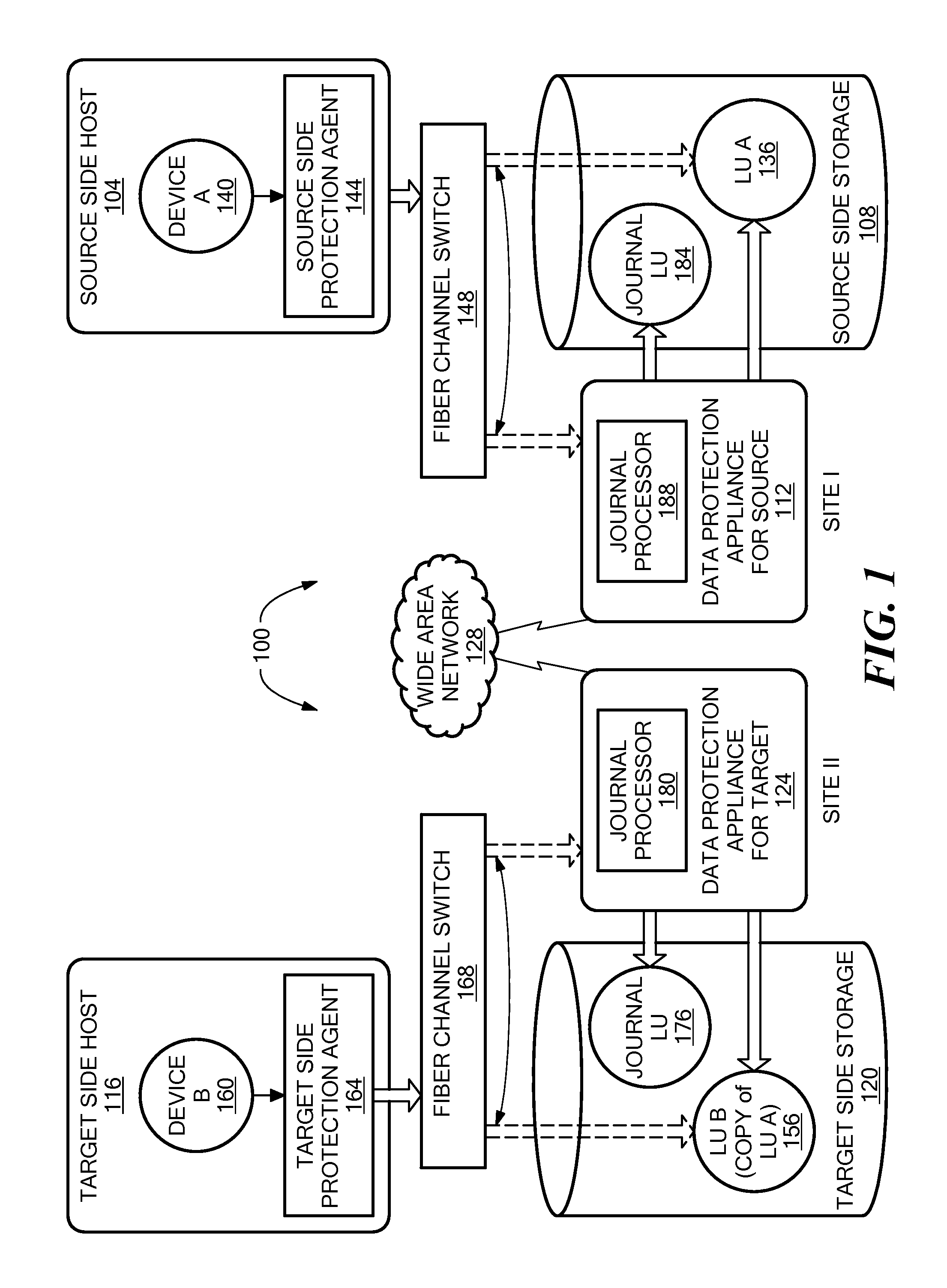
Referring to FIG. 1, a data protection system 100 includes two sites; Site I, which is a production site, and Site II, which is a backup site or replica site. Under normal operation the production site is the source side of system 100, and the backup site is the target side of the system. The backup site is responsible for replicating production site data. Additionally, the backup site enables roll back of Site I data to an earlier pointing time, which may be used in the event of data corruption of a disaster, or alternatively in order to view or to access data from an earlier point in time.
FIG. 1 is an overview of a system for data replication of either physical or virtual logical units. Thus, one of ordinary skill in the art would appreciate that in a virtual environment a hypervisor, in one example, would consume logical units and generate a distributed file system on them such as VMFS generates files in the file system and expose the files as logical units to the virtual machines (each VMDK is seen as a SCSI device by virtual hosts). In another example, the hypervisor consumes a network based file system and exposes files in the NFS as SCSI devices to virtual hosts.
During normal operations, the direction of replicate data flow goes from source side to target side. It is possible, however, for a user to reverse the direction of replicate data flow, in which case Site I starts to behave as a target backup site, and Site II starts to behave as a source production site. Such change of replication direction is referred to as a "failover". A failover may be performed in the event of a disaster at the production site, or for other reasons. In some data architectures, Site I or Site II behaves as a production site for a portion of stored data, and behaves simultaneously as a backup site for another portion of stored data. In some data architectures, a portion of stored data is replicated to a backup site, and another portion is not.
The production site and the backup site may be remote from one another, or they may both be situated at a common site, local to one another. Local data protection has the advantage of minimizing data lag between target and source, and remote data protection has the advantage is being robust in the event that a disaster occurs at the source side.
The source and target sides communicate via a wide area network (WAN) 128, although other types of networks may be used.
Each side of system 100 includes three major components coupled via a storage area network (SAN); namely, (i) a storage system, (ii) a host computer, and (iii) a data protection appliance (DPA). Specifically with reference to FIG. 1, the source side SAN includes a source host computer 104, a source storage system 108, and a source DPA 112. Similarly, the target side SAN includes a target host computer 116, a target storage system 120, and a target DPA 124. As well, the protection agent (sometimes referred to as a splitter) may run on the host, or on the storage, or in the network or at a hypervisor level, and that DPAs are optional and DPA code may run on the storage array too, or the DPA 124 may run as a virtual machine.
Generally, a SAN includes one or more devices, referred to as "nodes". A node in a SAN may be an "initiator" or a "target", or both. An initiator node is a device that is able to initiate requests to one or more other devices; and a target node is a device that is able to reply to requests, such as SCSI commands, sent by an initiator node. A SAN may also include network switches, such as fiber channel switches. The communication links between each host computer and its corresponding storage system may be any appropriate medium suitable for data transfer, such as fiber communication channel links.
The host communicates with its corresponding storage system using small computer system interface (SCSI) commands.
System 100 includes source storage system 108 and target storage system 120. Each storage system includes physical storage units for storing data, such as disks or arrays of disks. Typically, storage systems 108 and 120 are target nodes. In order to enable initiators to send requests to storage system 108, storage system 108 exposes one or more logical units (LU) to which commands are issued. Thus, storage systems 108 and 120 are SAN entities that provide multiple logical units for access by multiple SAN initiators.
Logical units are a logical entity provided by a storage system, for accessing data stored in the storage system. The logical unit may be a physical logical unit or a virtual logical unit. A logical unit is identified by a unique logical unit number (LUN). Storage system 108 exposes a logical unit 136, designated as LU A, and storage system 120 exposes a logical unit 156, designated as LU B.
LU B is used for replicating LU A. As such, LU B is generated as a copy of LU A. In one example, LU B is configured so that its size is identical to the size of LU A. Thus, for LU A, storage system 120 serves as a backup for source side storage system 108. Alternatively, as mentioned hereinabove, some logical units of storage system 120 may be used to back up logical units of storage system 108, and other logical units of storage system 120 may be used for other purposes. Moreover, there is symmetric replication whereby some logical units of storage system 108 are used for replicating logical units of storage system 120, and other logical units of storage system 120 are used for replicating other logical units of storage system 108.
System 100 includes a source side host computer 104 and a target side host computer 116. A host computer may be one computer, or a plurality of computers, or a network of distributed computers, each computer may include inter alia a conventional CPU, volatile and non-volatile memory, a data bus, an I/O interface, a display interface and a network interface. Generally a host computer runs at least one data processing application, such as a database application and an e-mail server.
Generally, an operating system of a host computer generates a host device for each logical unit exposed by a storage system in the host computer SAN. A host device is a logical entity in a host computer, through which a host computer may access a logical unit. Host device 104 identifies LU A and generates a corresponding host device 140, designated as Device A, through which it can access LU A. Similarly, host computer 116 identifies LU B and generates a corresponding device 160, designated as Device B.
In the course of continuous operation, host computer 104 is a SAN initiator that issues I/O requests (write/read operations) through host device 140 to LU A using, for example, SCSI commands. Such requests are generally transmitted to LU A with an address that includes a specific device identifier, an offset within the device, and a data size. Offsets are generally aligned to 512 byte blocks. The average size of a write operation issued by host computer 104 may be, for example, 10 kilobytes (KB); i.e., 20 blocks. For an I/O rate of 50 megabytes (MB) per second, this corresponds to approximately 5,000 write transactions per second.
System 100 includes two data protection appliances, a source side DPA 112 and a target side DPA 124. A DPA performs various data protection services, such as data replication of a storage system, and journaling of I/O requests issued by a host computer to source side storage system data. As explained in detail herein, when acting as a target side DPA, a DPA may also enable roll back of data to an earlier point in time, and processing of rolled back data at the target site. Each DPA 112 and 124 is a computer that includes inter alia one or more conventional CPUs and internal memory.
For additional safety precaution, each DPA is a cluster of such computers. Use of a cluster ensures that if a DPA computer is down, then the DPA functionality switches over to another computer. The DPA computers within a DPA cluster communicate with one another using at least one communication link suitable for data transfer via fiber channel or IP based protocols, or such other transfer protocol. One computer from the DPA cluster serves as the DPA leader. The DPA cluster leader coordinates between the computers in the cluster, and may also perform other tasks that require coordination between the computers, such as load balancing.
In the architecture illustrated in FIG. 1, DPA 112 and DPA 124 are standalone devices integrated within a SAN. Alternatively, each of DPA 112 and DPA 124 may be integrated into storage system 108 and storage system 120, respectively, or integrated into host computer 104 and host computer 116, respectively. Both DPAs communicate with their respective host computers through communication lines such as fiber channels using, for example, SCSI commands or any other protocol.
DPAs 112 and 124 are configured to act as initiators in the SAN; i.e., they can issue I/O requests using, for example, SCSI commands, to access logical units on their respective storage systems. DPA 112 and DPA 124 are also configured with the necessary functionality to act as targets; i.e., to reply to I/O requests, such as SCSI commands, issued by other initiators in the SAN, including inter alia their respective host computers 104 and 116. Being target nodes, DPA 112 and DPA 124 may dynamically expose or remove one or more logical units.
As described hereinabove, Site I and Site II may each behave simultaneously as production site and a backup site for different logical units. As such, DPA 112 and DPA 124 may each behave as a source DPA for some logical units, and as a target DPA for other logical units, at the same time.
Host computer 104 and host computer 116 include protection agents 144 and 164, respectively. Protection agents 144 and 164 intercept SCSI commands issued by their respective host computers, via host devices to logical units that are accessible to the host computers. A data protection agent may act on an intercepted SCSI commands issued to a logical unit, in one of the following ways: send the SCSI commands to its intended logical unit; redirect the SCSI command to another logical unit; split the SCSI command by sending it first to the respective DPA; after the DPA returns an acknowledgement, send the SCSI command to its intended logical unit; fail a SCSI command by returning an error return code; and delay a SCSI command by not returning an acknowledgement to the respective host computer.
A protection agent may handle different SCSI commands, differently, according to the type of the command. For example, a SCSI command inquiring about the size of a certain logical unit may be sent directly to that logical unit, while a SCSI write command may be split and sent first to a DPA associated with the agent. A protection agent may also change its behavior for handling SCSI commands, for example as a result of an instruction received from the DPA.
Specifically, the behavior of a protection agent for a certain host device generally corresponds to the behavior of its associated DPA with respect to the logical unit of the host device. When a DPA behaves as a source site DPA for a certain logical unit, then during normal course of operation, the associated protection agent splits I/O requests issued by a host computer to the host device corresponding to that logical unit. Similarly, when a DPA behaves as a target device for a certain logical unit, then during normal course of operation, the associated protection agent fails I/O requests issued by host computer to the host device corresponding to that logical unit.
Communication between protection agents and their respective DPAs may use any protocol suitable for data transfer within a SAN, such as fiber channel, or SCSI over fiber channel. The communication may be direct, or via a logical unit exposed by the DPA. Protection agents communicate with their respective DPAs by sending SCSI commands over fiber channel.
Protection agents 144 and 164 are drivers located in their respective host computers 104 and 116. Alternatively, a protection agent may also be located in a fiber channel switch, or in any other device situated in a data path between a host computer and a storage system or on the storage system itself. In a virtualized environment, the protection agent may run at the hypervisor layer or in a virtual machine providing a virtualization layer.
What follows is a detailed description of system behavior under normal production mode, and under recovery mode.
In production mode DPA 112 acts as a source site DPA for LU A. Thus, protection agent 144 is configured to act as a source side protection agent; i.e., as a splitter for host device A. Specifically, protection agent 144 replicates SCSI I/O write requests. A replicated SCSI I/O write request is sent to DPA 112. After receiving an acknowledgement from DPA 124, protection agent 144 then sends the SCSI I/O write request to LU A. After receiving a second acknowledgement from storage system 108 host computer 104 acknowledges that an I/O command complete.
When DPA 112 receives a replicated SCSI write request from data protection agent 144, DPA 112 transmits certain I/O information characterizing the write request, packaged as a "write transaction", over WAN 128 to DPA 124 on the target side, for journaling and for incorporation within target storage system 120.
DPA 112 may send its write transactions to DPA 124 using a variety of modes of transmission, including inter alia (i) a synchronous mode, (ii) an asynchronous mode, and (iii) a snapshot mode. In synchronous mode, DPA 112 sends each write transaction to DPA 124, receives back an acknowledgement from DPA 124, and in turns sends an acknowledgement back to protection agent 144. Protection agent 144 waits until receipt of such acknowledgement before sending the SCSI write request to LU A.
In asynchronous mode, DPA 112 sends an acknowledgement to protection agent 144 upon receipt of each I/O request, before receiving an acknowledgement back from DPA 124.
In snapshot mode, DPA 112 receives several I/O requests and combines them into an aggregate "snapshot" of all write activity performed in the multiple I/O requests, and sends the snapshot to DPA 124, for journaling and for incorporation in target storage system 120. In snapshot mode DPA 112 also sends an acknowledgement to protection agent 144 upon receipt of each I/O request, before receiving an acknowledgement back from DPA 124.
For the sake of clarity, the ensuing discussion assumes that information is transmitted at write-by-write granularity.
While in production mode, DPA 124 receives replicated data of LU A from DPA 112, and performs journaling and writing to storage system 120. When applying write operations to storage system 120, DPA 124 acts as an initiator, and sends SCSI commands to LU B.
During a recovery mode, DPA 124 undoes the write transactions in the journal, so as to restore storage system 120 to the state it was at, at an earlier time.
As described hereinabove, LU B is used as a backup of LU A. As such, during normal production mode, while data written to LU A by host computer 104 is replicated from LU A to LU B, host computer 116 should not be sending I/O requests to LU B. To prevent such I/O requests from being sent, protection agent 164 acts as a target site protection agent for host Device B and fails I/O requests sent from host computer 116 to LU B through host Device B.
Target storage system 120 exposes a logical unit 176, referred to as a "journal LU", for maintaining a history of write transactions made to LU B, referred to as a "journal". Alternatively, journal LU 176 may be striped over several logical units, or may reside within all of or a portion of another logical unit. DPA 124 includes a journal processor 180 for managing the journal.
Journal processor 180 functions generally to manage the journal entries of LU B. Specifically, journal processor 180 enters write transactions received by DPA 124 from DPA 112 into the journal, by writing them into the journal LU, reads the undo information for the transaction from LU B. updates the journal entries in the journal LU with undo information, applies the journal transactions to LU B, and removes already-applied transactions from the journal.
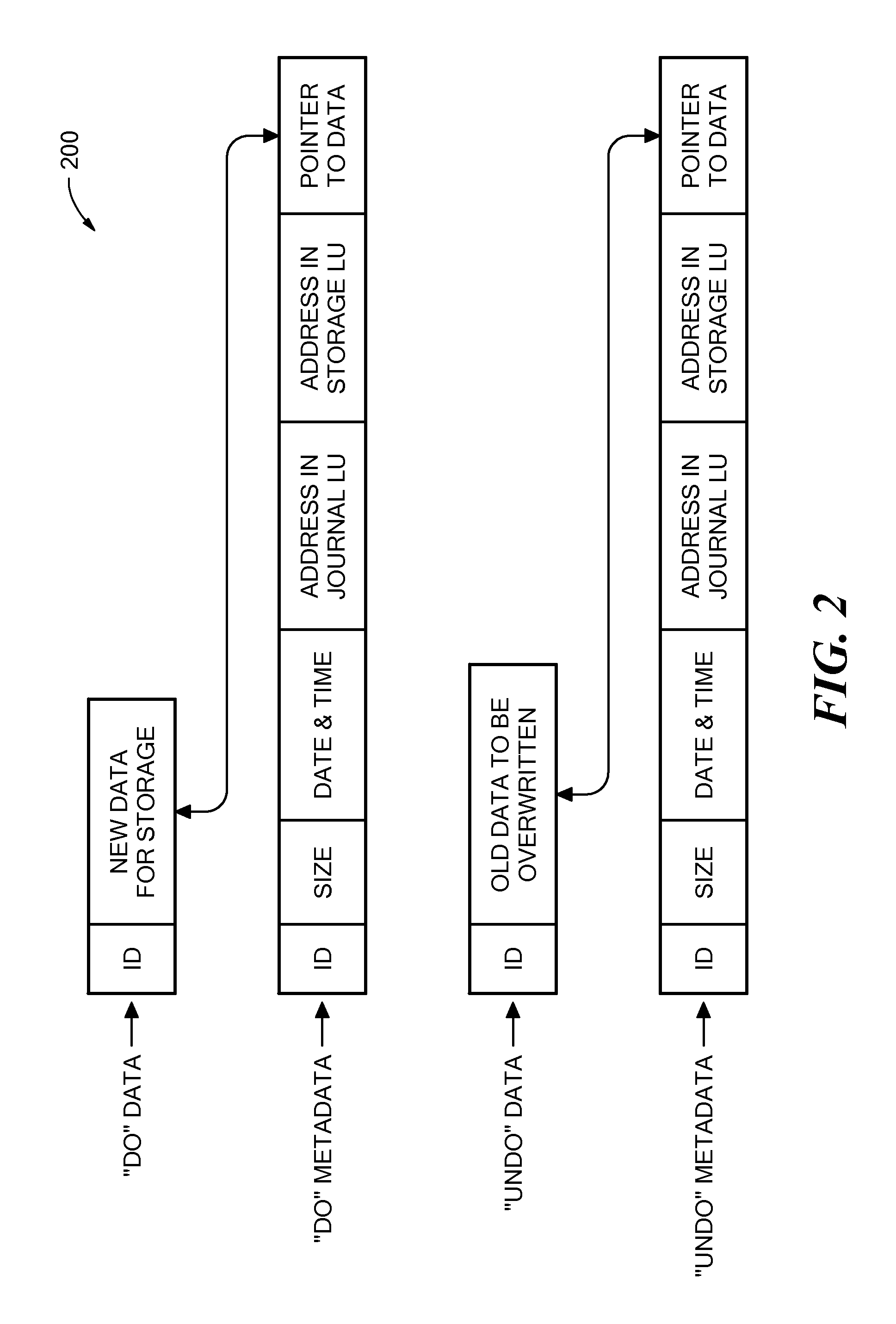
Referring to FIG. 2, which is an illustration of a write transaction 200 for a journal. The journal may be used to provide an adaptor for access to storage 120 at the state it was in at any specified point in time. Since the journal includes the "undo" information necessary to roll back storage system 120, data that was stored in specific memory locations at the specified point in time may be obtained by undoing write transactions that occurred subsequent to such point in time.
Write transaction 200 generally includes the following fields: one or more identifiers; a time stamp, which is the date & time at which the transaction was received by source side DPA 112; a write size, which is the size of the data block; a location in journal LU 176 where the data is entered; a location in LU B where the data is to be written; and the data itself.
Write transaction 200 is transmitted from source side DPA 112 to target side DPA 124. As shown in FIG. 2, DPA 124 records the write transaction 200 in the journal that includes four streams. A first stream, referred to as a DO stream, includes new data for writing in LU B. A second stream, referred to as an DO METADATA stream, includes metadata for the write transaction, such as an identifier, a date & time, a write size, a beginning address in LU B for writing the new data in, and a pointer to the offset in the DO stream where the corresponding data is located. Similarly, a third stream, referred to as an UNDO stream, includes old data that was overwritten in LU B; and a fourth stream, referred to as an UNDO METADATA, include an identifier, a date & time, a write size, a beginning address in LU B where data was to be overwritten, and a pointer to the offset in the UNDO stream where the corresponding old data is located.
In practice each of the four streams holds a plurality of write transaction data. As write transactions are received dynamically by target DPA 124, they are recorded at the end of the DO stream and the end of the DO METADATA stream, prior to committing the transaction. During transaction application, when the various write transactions are applied to LU B, prior to writing the new DO data into addresses within the storage system, the older data currently located in such addresses is recorded into the UNDO stream. In some examples, the metadata stream (e.g., UNDO METADATA stream or the DO METADATA stream) and the data stream (e.g., UNDO stream or DO stream) may be kept in a single stream each (i.e., one UNDO data and UNDO METADATA stream and one DO data and DO METADATA stream) by interleaving the metadata into the data stream.
FIGS. 3 to 5 depict systems and processes for initializing a backup snapshot on deduplicated storage consistent. Before deduplicated storage can provide continuous backup protection, it may be necessary to generate an initial backup snapshot of the source storage system. This initial backup snapshot may represent the earliest point-in-time backup that may be restored. As changes are made to the source storage system, journal files and/or new backups may be updated and/or synthesized to provide continuous protection. In some examples, the initial backup snapshot may be generated by streaming I/Os from a storage system scan to a data protection appliance, or by taking an initial snapshot of the storage system and transmitting the entire snapshot to deduplicated storage.
FIG. 3 depicts a system for generating an initial backup snapshot by scanning a source storage system and streaming I/Os to the deduplicated storage. Data protection application 300 may include journal processor 302, and may be in communication with deduplicated storage 304. In one example, deduplicated storage 304 may be target side storage residing at a backup site. Data protection appliance 300 may be similar to data protection appliance 112 and/or 124, and may be responsible for streaming I/Os to deduplicated storage 304.
In one example, a source storage system may be scanned and individual offsets may be streamed to data protection appliance 300. The offsets streamed from the scanned system may be referred to as initialization I/Os, and may be streamed sequentially to data protection appliance 300. For example, the scanned system may include offsets 0, 1, 2, and 3, comprising data A, B, C, and D. The initial scan may start at the beginning of the system, and transmit offset 0, followed by offset 1, and so forth.
As data protection appliance 300 receives the initialization I/Os, journal processor 302 may identify the offset data and metadata, and may stream the I/Os to metadata journal 306 and/or data journal 308 residing on deduplicated storage 304. Data journal 308 may include data stored within an offset, and metadata 306 may include metadata associated with that offset. Metadata could include, for example, an offset identifier, size, write time, and device ID. These journals may then be used to synthesize a backup snapshot on deduplicated storage 304, as described herein.
In some examples, a scanned storage system may operate in a live environment. As a result, applications may be writing to the storage concurrently with the scan process. If an application writes to a location that has already been streamed, the journal files and ultimately the synthesized snapshot may be out of date. To address this issue, application I/Os may be streamed concurrently with the initialization I/Os if the application I/Os are to an offset that has already been scanned. For example, consider Table 1:
TABLE-US-00001 Time Offset t0 t1 t2 t3 0 A A' 1 B B' 2 C 3 D D'
Table 1 depicts four different offsets, denoted as 0, 1, 2, and 3, and four times, t0, t1, t2, and t3. Letters A, B, C, and D may represent the data stored at the offsets. Time t0 may represent the offsets as they exist when the scan begins. These offsets may be streamed to data protection appliance 300 sequentially from 0 to 3. At time t1, however, the data at offset 1 is modified by an application from B to B'. Similarly, at t2 the data at offset 3 changes from D to D', and at t3 the data at offset 0 changes from A to A'. If the scan transmits the data at offset 1 before t1, B' may be missed since the change occurred after offset 1 was scanned and B was transmitted. Similarly, if the scan has not reached offset 3 before t2, only D' will be transmitted since D no longer exists. It may therefore be beneficial to transmit application I/Os to data protection appliance 300 if those I/Os write to an offset that has already been scanned. If the offset has not been scanned, it may not be necessary to transmit the application I/Os because the change will be transmitted when the scan reaches that offset.
Referring back to FIG. 3 and with continued reference to Table 1, offset metadata journal entries 310 and offset data journal entries 312 depict the state of metadata journal 306 and data journal 308 after the initial scan is complete. While there are only four offsets on the scanned storage system, there are six entries in the journal because the data in offset 0 and 1 was modified by an application after they were scanned. They each therefore have two entries: B and B'. Segment D was modified after the scan began, but before it was reached. Segment D therefore only has one entry: D'.
Metadata journal entries 310 and data journal entries 312 may include all of the data necessary to synthesize a backup snapshot of the scanned storage system. Data journal entries 312 may include the actual data from the storage system: A, B, B' C, A' and D'. Note that data D is not in the data journal 308 since it was modified on the storage system before its offset was scanned and transmitted. Metadata journal entries 310 may include metadata about the offsets. For example, metadata journal entries 310 may include an offset identifier, offset length, and write time, and volume/device ID. In the present example, metadata journal entries may include the entries shown in Table 2:
TABLE-US-00002 Offset/ Time Volume Offset Time 0 A 0 t0 1 A 8 kb t0 2 A 8 kb t1 3 A 16 kb t0 4 A 0 t3 5 A 24 kb t2
Table 2's metadata entries may correspond to the states shown in Table 1. The offset at location 0 may be offset 0, the offset at 8 kb may be offset 1, the offset at 16 kb may be offset 2, and the offset at 24 kb may be offset 3. The subscript of each journal entries 310 also identifies the offset associated with that metadata entry.
Deduplicated storage may use metadata journal 306 and data journal 308 to synthesize initial backup snapshot 314. First, metadata journal 306 may be queried to identify the most recent data associated with each offset. Next, the data may be retrieved from journal data file 308 and synthesized into backup snapshot 314. In some examples, synthesizing the backup snapshot may include generating and/or copying pointers rather than copying entire data blocks. This could be, for example, using a product such as EMC.RTM. Data Domain.RTM. Boost.TM.
For example, once the initial scan is complete, data journal 308 includes data B, B', C, A', and D'. A' and B' are the result of application I/Os occurring during the scan process, and therefore represent the present state of offsets 0 and 1. To generate backup snapshot 314, deduplicated storage may therefore retrieve A', B', C, and D' from the data journal 308 and synthesize them together.
Once initial backup snapshot 314 is synthesized, journal entries 310 and 312 may no longer be needed. In some examples, they may be removed from deduplicated storage 304 in order to conserve space. Alternatively, they may remain in the journals.
The systems and processes described in reference to FIG. 3 enable a system to generate an initial backup snapshot. Once the initial snapshot is generated, additional processes may enable continuous data protection and point-in-time recovery.
Referring to FIG. 4, an example of a process to generate an initial backup snapshot is a process 400, which includes processing blocks 401, 402, 404, 406, 408, 410, 412, 414 and 416. At block 401, sequential initialization I/Os are received from a scanned storage volume. These I/Os could be, for example, received at a data protection appliance, such as data protection appliance 300. In some examples, the initialization I/Os are read from the scanned storage volume by the data protection appliance.
At block 402, the initialization I/Os are streamed to a deduplicated storage. In an example, the deduplicated storage may be substantially similar to deduplicated storage 304. In some examples, the initialization I/Os are streamed to a data journal using a data stream, and to a metadata journal using a metadata stream. Each stream may be a file in the deduplicated storage. Additionally or alternatively, writes to the journal files may be performed through the EMC.RTM. Data Domain.RTM. Boost.TM. API or any other API.
At block 404, the initialization I/Os may be written to a journal on the deduplicated storage. This journal may be, for example, similar to metadata journal 306 and/or data journal 308. In an example, these journals may be in the same journal files. Alternatively, these may be separate files on the deduplicated storage system.
At block 406, application I/Os comprising writes to offsets on the scanned storage volume may be received. These application I/Os may also be received at a data protection appliance, such as data protection appliance 300.
At block 408, an offset associated with a specific application I/O is identified, and at block 410 it is determined whether the offset has already been streamed to the deduplicated storage.
This determination could be made on data protection appliance 300 using journal processor 302. If the offset has already been streamed, it must have already been scanned and included in an initialization I/O. If the offset has not been streamed, the storage volume scan may not have reached the offset on the storage volume.
At block 412, the application I/O is streamed to the deduplicated storage if its offset was included in a previously streamed initialization I/O. In an example, the application I/O is only streamed when its offset was included a previously streamed initialization I/O. Streaming the application I/O when its offset was included in a previous initialization I/O ensures that writes to the scanned volume are not missed during the initialization processes. In some examples, the application I/Os are streamed to a data journal using a data stream, and to a metadata journal using a metadata stream.
In an example, application I/Os are not streamed if they comprise writes to an offset that has not yet been scanned and streamed in an initialization I/O. This is because the data generated by the write will be included in the initialization I/O once the scan reaches that offset. This may reduce traffic between the data protection appliance and the deduplicated storage, and may reduce the workload on the deduplicated because the data will only be processed once.
At block 414, the application I/O is written to the journal. This journal may be the same journal as the initialization I/Os, or it may be a separate journal. In an example, the journal is data journal 308 and/or metadata journal 306.
At block 416, a backup snapshot is synthesized from the initialization I/Os and the application I/Os. This snapshot may be substantially similar to snapshot 314. In an example, the snapshot is synthesized by generating data pointers in a new file on the deduplicated storage. Additionally or alternatively, the pointers may be copied from the data journal. These pointers may point to the data referenced and/or included in the journal. Synthesizing the snapshot using pointers may improve performance, as the data may not need to be replicated.
FIG. 5 depicts an additional or alternative example for initializing a backup snapshot. The system shown in FIG. 5 may include data protection appliance 500, journal processor 502, and deduplicated storage 504. These elements may be substantially similar to those described in reference to FIG. 3.
Data protection appliance 500 may take a snapshot of a storage system and transmit that snapshot to deduplicated storage 504 for storage as a file. In an example, this is different than streaming initialization I/Os and synthesizing a snapshot from journal files.
Rather than generating the snapshot on the deduplicated storage, the backup snapshot is generated using the data protection appliance and transmitted to deduplicated storage to be stored as backup snapshot 514.
In an example, journal processor 502 may stream application I/Os to deduplicated storage, and those application I/Os may be stored in metadata journal 506 and data journal 508. Like the journals of FIG. 3, metadata journal 506 may include metadata journal entries 510, and data journal 508 may include data journal entries 512. These journals may be used to synthesize a second backup snapshot or enable point-in-time recovery, as described below.
The systems and processes described in reference to FIGS. 3 to 5 enable a system to generate an initial backup snapshot. Once the initial snapshot is generated, additional processes may enable continuous data protection and point-in-time recovery.
Referring to FIG. 6, a system and process for maintaining backups using continuous data replication is described. As datasets increase in size, backing them up to remote or local backup devices becomes increasingly costly and complex. Additionally, traditional backup processes may not allow point-in-time recovery since the backups occur on a periodic, rather than continuous, basis. The methods and systems described herein provide continuous backup protection as writes are made to a source device, thereby reducing backup cost and complexity, and may allowing point-in-time recovery for backed up files.
The system of FIG. 6 includes a data protection appliance 600, a journal processor 602, and a deduplicated storage 604. These elements may be substantially similar to those described in reference to FIG. 3. Deduplicated storage 604 may include a backup snapshot 614, a metadata journal file 606, and a data journal file 608. In one example, backup snapshot file 614 is synthesized in a manner substantially similar to backup snapshot 314, and may be generated using metadata journal entries 610 and data journal entries 612.
As users, applications, and other processes access and use the source storage system, data on that system may change and/or new data may be generated. As a result, initial backup snapshot 614 may become stale. If the source storage system should fail, there is a chance that any new or modified data may be lost. To address this concern, data protection appliance 600 may receive and stream application I/Os to deduplicated storage system 604 on a continuous basis, even after initial backup snapshot 614 is synthesized. Streaming the application I/Os allows the backups on deduplicated storage 604 to remain up-to-date, without needing to perform additional backups of large datasets. This may reduce network traffic, reduce workloads, and conserve space on deduplicated storage 604.
For example, new metadata entries 611 and new data journal entries 613 represent I/Os made after initial backup snapshot 614 was synthesized. These entries may be written to metadata journal 606 and data journal 608, as shown in FIG. 6, or they may be written to separate journal files. In FIG. 6, data A' and C were modified on the source storage device, and the journal entries therefore include A'' and C'.
Periodically, new backup snapshots may be synthesized from a previous backup snapshot and new journal entries. For example, second backup snapshot 616 may be synthesized from initial backup snapshot 614, new metadata journal entries 611, and new data journal entries 613. Second backup snapshot 616 may be used to restore source storage system up to the point-in-time the last journal entry was received. That is, backup snapshot 616 represents a backup of the source storage system at a later timestamp than initial backup snapshot 614.
In one example, synthesizing second backup journal entry 616 may be substantially similar to synthesizing the initial backup snapshot 614. Rather than synthesizing all of the data from data journal 608, however, unchanged data may be synthesized from initial backup snapshot 614. In one example, this synthesis may include copying and/or generating a data pointer. For example, in FIG. 6 the solid arrows between initial backup snapshot 614 and second backup snapshot 616 represent unchanged data that is common between the two. In this case, only B' and D' remain unchanged. The dashed arrows represent new or changed data that needs to be synthesized into second backup snapshot 616. In FIG. 6, A' is changed to A'', C is change to C'. Synthesizing the data into second backup snapshot 616 therefore results in A'', B', C', D'.
Additionally or alternatively, second backup snapshot 616 may be synthesized entirely from journal entries. Rather than synthesizing unchanged data from initial backup 614, deduplicated storage 604 may retrieve the unchanged data from data journal entries 612. For example, B' and D' may be synthesized from data journal entries 612 rather than from initial backup snapshot 614.
Additional backup snapshots, such as second backup snapshot 616, may be generated periodically or on demand. For example, a user policy may specify that new snapshots should be generated every week. Additionally or alternatively, a user may be preparing to perform some risky operations on the source storage system, and may demand that a snapshot be generated in case something goes wrong. These policies may be maintained and applied using data protection appliance 600, deduplicated storage 604, and/or an external system.
Referring to FIG. 7, an example of a process to maintain backup snapshots using continuous data replication is a process 700, which includes processing blocks 701, 702, 704, 706, 708 and 710. At block 701, an initial snapshot of a source storage system may be generated. This initial snapshot may be substantially similar to initial backup snapshot 614, and may be generated using any one of the processes described in reference to FIGS. 3 to 5. Additionally or alternatively, the initial snapshot may be any previously generated snapshot. For example, the initial snapshot may be similar to second backup snapshot 616, and may be used in conjunction with journal files to generate a third backup snapshot.
At block 702, application I/Os comprising writes to the source storage system may be received. These writes may update existing data or generate new data. In some examples, the application I/Os may be received by a data protection appliance, such as data protection appliance 600.
At block 704, the application I/Os may be written to a journal file. This journal file may be substantially similar to metadata journal file 606 and/or data journal file 608. In some examples, the application I/Os may be written to one or more existing journals. Alternatively, application I/Os arriving after a snapshot is synthesized may be written to their own unique journals. This may be beneficial, for example, when maintaining different levels of backup granularity, as described below.
In some examples, the application I/Os are sequentially written to the journal as they are received. For example, if application I/Os arrive in order B, C, A, their corresponding entries in the journal will also be B, C, A.
At block 706, a second snapshot may be synthesized from the initial backup snapshot and the journal. The second snapshot may be substantially similar to second backup snapshot 616, and the synthesis process may be similar to that depicted by the solid and dashed lines. In some examples, the second snapshot may be synthesized entirely from journal files rather than use the initial backup snapshot.
During and/or after the synthesis process, additional application I/Os may be received at block 708. These application I/Os could be used, for example, to generate the third backup snapshot in the future, and may be processed in a manner similar to all the other application I/Os described herein.
At block 710 the additional application I/Os may be written to a journal file. They may be written to the same journal as the previous I/Os, or they may be written to a new journal file.
Referring to FIG. 7A, an example of a process to synthesize snapshots used for continuous data replication is a process 712, which includes processing blocks 713, 714, 716 and 718. At block 712, a metadata journal may be read. This metadata journal could be, for example, metadata journal file 606. In some examples, the metadata journal may be read using a journal processor on a data protection appliance. Additionally or alternatively, the read operation may be local to the deduplicated storage device.
At block 714, the latest I/Os for each offset may be identified. For example, metadata journal file 606 includes journal entries 610 and 611. The latest entry for offset 0 is A'', 1 is B', 2 is C', and 3 is D'. In some examples, journal entries 610 and 611 may be written to different journals. In such some examples, the only I/Os identified would be A'' and C' since we are synthesizing a snapshot from initial backup snapshot 614.
At block 716, a synthesis plan may be generated. This plan may identify where each I/O should be synthesized from. For example, the synthesis plan may only identify A'' and C' for synthesis from data journal 608. The B' and D', in contrast, may be obtained from initial backup snapshot 614 since they have not changed.
At block 718, the backup snapshot may be synthesized. This backup snapshot could be, for example, substantially similar to backup snapshot 616.
The system and processes described herein may enable additional backup snapshots to be synthesized from journal entries and existing snapshots. In some examples, the journal entries may be application I/Os which are continuously streamed to a data protection appliance. While these snapshots may provide additional data protection, they may only allow data that exists in the snapshots to be recovered. Combining snapshots and journal files may, however, allow any point-in-time recovery.
When datasets are backed-up on a periodic rather than continuous basis, data recovery may only be available for specific time intervals. For example, if a dataset is backed up at the end of every business day, the only data that is available for recovery is the data as it exists at the end of the day. Continuous backups, however, may allow recovery of data at any, or nearly any, point-in-time. By transmitting application I/Os to a backup location as they occur, an interim snapshot may be synthesized between scheduled snapshots and data may be recovered.
FIGS. 8 and 9 depict a system and process to synthesize an interim snapshot for point-in-time recovery. In one example, the system may include data protection appliance 800, journal processor 802, and deduplicated storage 804. The system may also include metadata journal file 806, comprising metadata journal entries 810 and 811, and data journal file 808, comprising data journal entries 812 and 813.
Data protection appliance 800 may receive application I/Os as they are made to a source storage system. In some examples, journal processor 802 may write those I/Os to metadata journal file 806 and data journal file 808. Initialization journal entries 810 and 812 may be used to synthesize initial backup snapshot 814. Metadata entries 811 and data journal file entries 813 may be application I/Os made to the source storage volume after or while initial backup snapshot 814 was synthesized. These elements may be substantially similar to those described in reference to FIG. 6.
In one example, metadata journal entries 811 and data journal entries 813 may be used to synthesize interim snapshot 816. Interim snapshot 816 may then be used as a source for point-in-time recovery. For example, application I/Os A'' and C' may be streamed to deduplicated storage as they are made to the source storage system. A user may then decide they wish recover data from the point-in-time immediately after application I/O A'' was streamed. When the user's request arrives, the most recent snapshot may be initial backup snapshot 814, which does not include A'' or C'. To respond to the user's request, deduplicated storage 804 may synthesize interim snapshot 816. This snapshot may include unchanged data from initial backup snapshot 814, as shown by the solid black arrows, and application I/O A'' synthesized from data journal file 808, as shown by the dashed arrow. Note that interim snapshot 816 does not include C'. This is because the user requested data recovery at a point-in-time before C' may made.
In one example, the data from interim snapshot 816 may be transmitted back to the source storage system and recovered. Additionally or alternatively, it may be exposed to a host as LUN, as described in reference FIGS. 12 and 13. Interim snapshot 816 may be deleted after recovery, or may be retained. In some examples, if interim snapshot 816 is generated at a point-in-time sufficiently close to a scheduled synthesis time, the scheduled synthesis may be cancelled and interim snapshot 816 may be treated as second backup snapshot 616.
Referring to FIG. 9, an example of a process to perform recovery for a point-in-time is a process 900, which includes processing blocks 901, 902, 904, 906 and 908. At block 901, a request to recover some data is received. This request could be, for example, received at data protection appliance 800 and/or deduplicated data storage 804. In one example, the request may specify a file representing a LUN to recover, or it may be a request to recover an entire system. Additionally or alternatively, the request may specify a point-in-time for the recovery. The point-in-time may be a date, event, or any other mechanism to identify a specific time. In some examples, the point-in-time may be between snapshots.
At block 902, a snapshot nearest the point-in-time may be identified. The snapshot could be, for example, initial backup snapshot 814.
At block 906, a recovery snapshot may be synthesized. This recovery snapshot could be, for example, substantially similar to interim snapshot 816. If the recovery snapshot is synthesized using a snapshot from an earlier point-in-time, I/Os stored in a journal file may be applied to synthesize the recovery snapshot.
At block 908 the recovery snapshot may be provided in response to the request. For example, the recovery snapshot may be exposed as a LUN and mounted on a host computer, or exposed as a network file system share. Additionally or alternatively, the recovery snapshot may be transmitted back to the source storage system. In some examples, only a portion of the snapshot, such as a specific file, may be provided.
Combining backup snapshots, journals, and continuous data replication may provide point-in-time recovery capabilities. As more data is written to and/or modified on a source storage system, however, the number of journals and snapshots may increase. In some examples, data protection windows may be used to manage this data growth.
As the number of snapshots and journals on the deduplicated storage grows, more space may be required. Deleting snapshots and journals may result in important information being lost, and adding to space to the deduplicated storage may be expensive. To address these concerns, backup windows and policies may be defined. Backup windows may be defined intervals designating which snapshot and journals should be stored, and for how long.
FIGS. 10 and 11 depict a system and process to define backup granularity using data protection windows. FIG. 10 shows seventeen snapshot files, labeled S1 through S17, stored on a deduplicated storage device. These snapshots may be generated and maintained in a manner substantially similar to that described above. The deduplicated storage device may also include six journal files, labeled J1 through J6, which may be used to synthesize new snapshots or perform point-in-time recovery.
FIG. 10 also includes three data protection windows: short-term protection window 1000, mid-term protection window 1002, and long term protection window 1004. Each of these protection windows may have an associated policy specifying actions to take on any snapshot and/or journal file within the protection window. For example, one policy may be "delete all journals within this protection window." While the examples described herein address deletion and/or retention policies, any other policy which may be applied to the journals and/or snapshots is consistent with this disclosure.
Short-term protection window 1000 may be defined to protect both snapshots and journal files allowing for point-in-time recovery. This window may be particularly beneficial for snapshots that were generated recently and/or were generated on demand by a user. On demand generation may signify that the snapshot is more important than a scheduled snapshot because a user must go out of their way to generate it. Further, it may be more likely that a user needs to recover data which was modified or generated recently.
Mid-term protection window 1002 may include only snapshot files. As time progresses and journal files move from short-term protection window 1000 into mid-term protection window 1002, they may be deleted. While deleting journal files may prevent most point-in-time recovery, the snapshots may be maintained in mid-term protection window. As a result, some level of point-in-time recovery is preserved. Specifically, any data included in one of the maintained snapshots may be recovered. Mid-term protection window therefore balances storage needs with recovery needs.
As snapshots move from mid-term protection 1002 window into long-term protection window 1004, certain snapshots may be deleted. Point-in-time recovery may be less important for long-term backups because of their age. The deleted snapshots may be chosen based on a policy, such as size or a user assigned priority. Additionally or alternatively, they may be arbitrarily chosen (for example, only retaining every fifth snapshot).
In some examples, data protection windows may be defined and maintained using a data protection appliance, a deduplicated storage device, and/or an external system. For example, if the data protection window is defined using a deduplicated storage device, that device may delete the journals and/or snapshots as the move from one data protection window into another. In some examples, the data protection windows may change dynamically based on available space on the deduplicated storage device. For example, if there is a large amount of available space the short-term protection window may be very large, and/or the mid-term and long-term protection windows may not exist. Similarly, if there is not much available space the long-term protection window may be very long.
Referring to FIG. 11, an example, of a process to define and apply data protection windows is a process 1100, which includes processing blocks, 1101, 1102, 1104, 1106, 1108, 1110, 111, 1112, 1114 and 1116. At block 1101, a plurality of backup snapshots may be initialized on a deduplicated storage. These snapshots may be initialized or generated using any of the systems or methods described herein.
At block 1102, a plurality of journals may be initialized on the deduplicated storage device. These journals may be generated from application I/Os received from source side storage, and may provide point-in-time recovery. In some examples, any of the processes described herein for generating and/or maintaining journals may be used.
At block 1104, a first backup window comprising a first time range may be defined. The time range may specify the amount of time snapshots and/or journals remain inside the backup window. In some examples, the time range is dynamically based on the available storage on a deduplicated storage device.
At block 1106, the first backup window may be applied to the backup snapshots and journals. In some examples, the first backup window may be defined to maintain all of the snapshots and journals it covers. This may permit point-in-time recovery of data from those files. In some examples, the first backup window is substantially similar to the short-term backup window described above.
At block 1108, second backup window comprising a second time range may be defined. This second backup window may include a second time range similar to the first window's time range. In some examples, the second backup window only applies to journals, and may be substantially similar to mid-term backup widow 1002.
At block 1110, the second backup window may be applied to the journals. This may occur as the journals move from the first backup window into the second backup window. For example, as time progresses the journal files may move outside the time range defined in the first protection window. This may be, for example, because the time range is shorter than the journals age. The journal may move into the time range specified in the second backup window, and that backup window may be applied.
At block 1111, as journals move into the second time range the may be deleted. In some examples, this may mean deleting every journal inside the second time range.
Additionally or alternatively, only select journals may be deleted. For example, the data protection window may have an associated policy specifying that only every second journal should be deleted.
At 1112, a third backup window comprising a third time range may be defined. This third backup window may be substantially similar to long-term window described above. In some examples, the third time range may be a catch-all, meaning it applies to any journal and/or backup snapshot not covered by the first backup window or the second backup window.
At 1114, the third backup window may be applied to any remaining snapshots and/or journals. In some examples, the journals have all been deleted and the third backup window is only applied to snapshot files.
At block 1116, a number of snap shots inside the third time range may be deleted. The number of snapshots to delete may be based on a policy, such as only retain every tenth snapshot, in some examples only a daily snapshot may be kept, or any other policy may be applied (for instance keep ten daily snapshots and then ten weekly snapshots and then ten monthly snapshots, and so forth).
The data protection windows described herein may provide varying degree of backup granularity. More recent and/or important information may include both snapshots and journal files, which longer term backups may only include periodic backup snapshots.
Data backups are only useful if they can be accessed and/or retrieved when needed. Accessing backup snapshots may allow a user or system to retrieve data needed for recovery. For a system-wide recovery, the entire backup snapshot may be retrieved. In some examples, however, it may be beneficial to allow a user to access the snapshot directly to retrieve discrete pieces of data.
FIGS. 12 and 13 depict a system and process for providing access to data snapshots. The system of FIG. 12 may include data protection appliance 1200 comprising journal processor 1202, deduplicated storage 1204, and host 1222. In some examples, deduplicated storage may include metadata journal 1206, data journal 1208, backup snapshot 1214, and recovery snapshot 1216. Recovery snapshot 1216 may be a synthesized snapshot for point-in-time recovery, as described in reference to FIG. 8. Metadata journal 1206 may include metadata journal entries 1210 and 1211, and data journal 1208 may include data journal entries 1212 and 1213. In some examples, these elements may be substantially similar to those described in reference to the figures above.
In some examples, a user may need to recover data from recovery snapshot 1216. Transmitting the entire snapshot over a network, however, may be inefficient given the snapshot's size. For example, if recovery snapshot is several gigabytes, and a user wishes to recover a file on the snapshot that is only a few megabytes, transferring the entire recovery snapshot 1216 may consume an unnecessary amount of network bandwidth.
Rather than transmitting recovery snapshot 1216 over a network, deduplicated storage 1204 may generate block LUN 1218 on top of the snapshot. LUN 1218 may be exposed and mounted on host 1222 as device 1220. A user may access LUN 1218 through device 1220, and could thereby browse the snapshot for the data they wish to recover. Once the data is located, it may be transmitted to the source storage system directly, through data protection appliance 1200, or through host 1222.
In some examples, the source storage system may be down for a prolonged period of time, but a user may still need to access their data. In such an example, the user may mount LUN 1218 as device 1220. Rather than merely recovering data, however, the user may make writes to the recovery snapshot 1216 through LUN 1218. The writes may be tracked, for example using metadata journal 1206 and data journal 1208. Once the source storage system is accessible again, a difference between the latest point in time of the volume at the storage array and the current data at recovery snapshot 1216 may be taken. The results of the difference may indicate which data has changed, and those changes may be communicated back to the source storage system. This may allow a user to continue to access and make changes to their data, even while the source storage system is down.
In one example block LUN 1218 may not be generated and mounted on host 1222. Instead, the recovery snapshot may be exposed as a network file system ("NFS") share. Host 1222 may accessed the NFS share, retrieve data, and/or perform write operations.
In some examples, recovery snapshot 1216 may include a virtual machine disk ("VMDK") file. The VMDK file may be, for example, accessed directly by an NFS mount and the virtual machine may boot using the VMDK file. Host 1222 may interact with the VMDK, and may make changes in the process. The VMDK may be transferred to the source side storage when it is available. In some examples, the transfer may occur while the VMDK is running.
Referring to FIG. 13, an example of a process to expose a recovery snapshot as a logical unit is a process 1300, which includes processing blocks 1301, 1302, 1304, 1306, 1308 and 1310. At block 1301, a recovery snapshot may be exposed as a LUN. This exposure could occur, for example, by generating a block LUN on top of the snapshot. In some examples, the snapshot resides on a deduplicated storage, and the block LUN is generated on that storage.
At block 1302, the LUN may be mounted on a host device. Once mounted, the host device may access and interact with the LUN as if it were a local drive. For example, the host device may make read and/or write requests to the LUN.
At block 1304, the deduplicated storage may receive I/Os for the LUN from the host device. These I/Os could be, for example, read and/or write requests.
At block 1306, the I/Os may be applied to the recovery snapshot to generate a modified recovery snapshot. For example, the I/Os could modify recovery snapshot 1216 to change data E to E'.
At block 1308, a difference between the modified recovery snapshot and a backup snapshot may be identified. This difference could be identified, for example, using API's native to the deduplicated storage device.
At block 1310, the difference may be transmitted to a recovery device. In some examples, the recovery device may be a source storage system. Additionally or alternatively, the difference may be transmitted in response to a request. For example, a user may access the system and request the difference between the modified recovery snapshot and a backup snapshot.
Referring to FIG. 13A, an example of a process to recover a logically corrupted source storage system is a process 1312, which includes processing blocks 1313, 1314, 1316, 1318, 1320, 1322, 1324, 1326 and 1328. In some examples, a user may wish to recover the data on the corrupted system. The user may identify a point-in-time where the system is believed to not be corrupt, and synthesize a snapshot comprising data between that point-in-time and the latest point on the storage system. This snapshot may be applied to the system to recover the corrupt data.
At block 1312, a request may be received from a user to recover data. The request may include a point-in-time identifying a time when the user believes the data was not corrupt. In some examples, the data between the point-in-time and the present time must be recovered because it is corrupt on the source storage system. Since the application I/Os are made to the deduplicated storage in real time, however, the data on that location may be correct.
At block 1314, a recovery snapshot may be synthesized for the point-in-time. This recovery snapshot could be, for example, synthesized in a manner substantially similar to the described above.
At block 1316, a difference may be identified between the recovery snapshot and the latest backup snapshot. The latest backup snapshot may be a snapshot for a point-in-time later than the recover snapshot. For example, if the recovery snapshot includes A, B, C, D, and E, and the latest backup snapshot includes A', B, C', D, and F, the difference may be A' and C'. In some examples, the difference is identified on a deduplicated storage device and may use native APIs.
At block 1318, the difference may be added to a recovery list as entries in that recovery list. In some examples, the entries may be metadata associated with the difference. For example, the recovery list may include metadata entries for A' and C'.
At block 1320, metadata entries in the latest journal file may be identified. The metadata entries may include metadata that is not included in the latest synthesized backup. For example, they may include application I/Os that arrived after the latest backup snapshot was synthesized. This identification process could occur, for example, at a journal processor.
At block 1322, the metadata journal entries may be added to the recovery list. For example, if the entries include A'' and D', the new recovery list may include A'', C', and D'. At block 1324, additional metadata entries may be identified in a data protection appliance memory. In some examples, these entries may be for application I/Os which have arrived at the data protection appliance, but have not yet been transmitted and/or written to the journal file.
At block 1326, the additional metadata entries may be added to the recovery list. For example, if the data protection appliance's memory includes B', the recovery list may include A'', B', and D'.
At block 1318 data associated with the metadata entries may be identified and transmitted back to the source storage system for recovery. If the metadata includes pointers, for example, the data pointed to by the pointers may be transmitted back to the source storage system.
For large, heavily used source storage systems, the volume of application and/or initialization I/Os may be too great for a single data protection appliance to maintain. If a data protection appliance is overburdened, journal files may not be up-to-date and valuable data may be lost if the source storage system fails. Using multiple data protection appliances may alleviate this risk.
FIGS. 14 and 15 show a system and method for generating backup snapshots using multiple data protection appliances. The system depicted in FIG. 15 includes data protection appliance 1400 and data protection appliance 1401. In some examples, each of these data protection appliances is responsible for protecting specific portions of a LUN in a source storage system. For example, data protection appliance 1400 may be responsible for protecting a first chunk of a LUN in a common storage array, and data protection appliance 1401 may be responsible for protecting a second chunk in a LUN of the common storage array. If an application I/O is made to the first chunk, it is received by data protection appliance 1400 and written to journal file 1406 using journal processor 1402. Similarly, if an application I/O is made to the second chunk it may be received by data protection appliance 1401 and written to journal file 1407 using journal processor 1403. In this manner, all of the application I/Os may be written to a journal using two data protection appliances.
While there are only two data protection appliances shown in FIG. 14, it should be appreciated that any number of data protection appliances is consistent with this disclosure. For example, the source storage system may be divided into five sections or chunks which are protected by five separate and distinct data protection appliances.
In some examples, there is no overlap between the chunks protected by different data protection appliances. For example, data protection appliance 1400 will not protect a chunk that is also protected by data protection appliance 1401. Alternatively, there may be protection overlap for redundancy.
In some examples, the chunks of the LUN may not consist of continuous parts. For instance, a first chunk may include 1 MB portions which start at an offset which is 2N MB, while chunk 2 includes 1 MB portions starting an offset of 2(N+1) MB.
Journals 1406 and 1407 may be separate journal files accessible only by their associated data protection appliance. Alternatively, they may be the same journal file accessible by both data protection appliances. Additionally, journals 1406 and 1407 may include both a metadata journal file and a data journal file, as described above. The metadata journal and data journals are not shown in FIG. 14 for ease of illustration, but they may still be part of journal file 1406 and 1407.
Journals files 1406 and 1407 may be used by deduplicated storage 1404 to synthesize snapshots for each of the regions their respective data protection appliances protect. For example, suppose source storage system includes data A, B, C. D, and E. Data protection appliance 1400 may be responsible for protecting A, B, and C, and data protection appliance 1401 may be responsible for protecting D and E. As a result, journal 1406 includes data and metadata for A, B, and C, but not D or E. Similarly, journal 1407 includes data and metadata for D and E, but not A, B, or C.
Since each journal only includes data associated with specific regions of the source storage system, neither journal alone can synthesize a complete backup snapshot. First snapshot 1408 may be synthesized using the data and metadata from journal file 1406.
Snapshot 1408 may include A', B, and C', but does not include data for D or E as shown by the hash marks in the Figure. Similarly, second snapshot 1409 includes data D' and E', but no data for A, B, or C. Neither of these snapshots therefore represents a complete backup snapshot of the source storage system.
Backup snapshot 1410 may be synthesized by merging first snapshot 1408 and second snapshot 1409. Backup snapshot 1410 may include a complete backup of the source storage system. In some examples, this synthesis may be accomplished by synthesis data from each snapshot 1408 and 1409 into snapshot 1410. Alternatively, first snapshot 1408 may be merged into second snapshot 1409 to generated backup snapshot 1410. Once backup snapshot 1410 is synthesized, snapshots 1408 and 1409 may be deleted to conserve space, or retained for redundancy.
In some examples, first snapshot 1408 and second snapshot 1409 may never he generated. Instead, backup snapshot 1410 may synthesize the necessary data directly from journal files 1406 and 1407.
Referring to FIG. 15, an example of a process to flow chart to synthesize a backup snapshot from data received from multiple data protection appliances is a process 1500, which includes processing blocks 1501, 1502, 1504, 1506 and 1508. At block 1501, a first set of sequential I/Os may be streamed from a data protection appliance to a deduplicated storage device. The I/Os could be, for example, sequential I/Os. In some examples, the I/Os may be for a specific section, chunk, or region of the source storage system.
At block 1502, a second set of sequential I/Os may be streamed from a second data protection appliance to the deduplicated storage. In some examples, these I/Os may be for a separate section of the source storage system than those streamed from the first data protection appliance. While the first set of sequential I/Os and the second set of sequential I/Os may be for different regions of a source storage system, such as a data array, they may both be made to the same source data system. In other words, the application I/Os may be made to a common source, which is divided into chunks protected by separate data protection appliances.
At block 1504, a first snapshot may be synthesized from the first journal file. This snapshot could be, for example, snapshot 1408. In some examples, the first snapshot only includes data included in the first journal.
At block 1506, a second snapshot may be synthesized from the second journal. This snapshot could be substantially similar to snapshot 1409, and may only include data from the second journal file.
At block 1508 the first snapshot and the second snapshot may be merged to generate a backup snapshot. This could be, for example, backup snapshot 1410.
Referring to FIG. 16A, a replication system 1600 includes a host 1602, a storage array 1604, a data protection appliance (DPA) 1606, a deduplication device 1608 at a production site and a deduplication device 1608' at a replication site. The deduplication device 1608 and the deduplication device 1608' are connected by a network 1610 (e.g., a wide area network (WAN).
The storage array 1604 includes a splitter 1622 and logical unit devices (LUNs) 1624. The deduplication device 1608 includes snapshot files of the logical units 1642, journal files 1644 and configuration files 1646. The snapshot files of the logical units 1642 include a file of a snapshot of a logical unit for different points-in-time. The journal files 1644 include journal files that include the differences between two snapshots of a logical unit. The configuration files include volume IDs, consistency group data and any configuration data required to recover the storage array 1604 and configuration of the replication system 1600. For example, the configuration file may include a list of consistency groups protected in the deduplication storage, a list of the devices of each consistency group including the sizes and any other relevant information about the devices. In some examples, the deduplication storage may not contain journal files and contain only point-in-time files of the volume data.
The DPA 1606 backs up the storage array 1604 to the backup device 1608. The deduplication device 1608 is backed up to the deduplication device 1608'. In particular, the snapshot files of the logical units 1642, the journal files 1644 and the configuration files 1646 are backed up to the deduplication device 168' as logical units 1642', journal files 1644' and configuration files 1646', respectively.
Referring to FIG. 16B, in the event of a failure of the production site components the deduplication device 1608' may be used to recover the data which existed on storage array 1604 into storage array 1620. For example, a DPA 1614 connected to the deduplication device 1608' and a storage array 1620 connected to the DPA 1614 form a recovery system 1600'. In particular, the DPA 1614 may be used to access the deduplication device 1608' to reform the storage array 1604 onto the storage array 1620 using, for example, a process 1700 (FIG. 17).
Referring to FIG. 17, an example of a process to recover a storage array using a remote deduplication device is a process 1700. Process 1700 extracts configuration files from the deduplication device (1702). For example, the configuration files 1646' are extracted from the deduplication device 1608'.
Process 1700 configures the storage array (1708). For example, the DPA 1614 uses the configuration files 1646' to set up the logical units including their volumes (e.g., Volume IDs and size) and consistency groups. In some examples, hosts are also configured and zoned to be able to access newly created logical units. The DPA 1614 is also configured with a consistency group mapping between recovery files (e.g., the snapshot files of the logical units 1642' and the journal files 1644') in the backup deduplication device 1608' and the storage array 1620.
Process 1700 notifies a user what point-time is available to recover (1712). For example, the DPA 1614 reads the files of the snapshots of logical units 1642' and the journal files 1644' and allows a user to recover point in time into the volumes generated at processing block 1708
Process 1700 receives a point-in-time to recover (1718). For example, the user sends to the DPA 1614 the point-in-time to recover.
Process 1700 extracts the point-in-time data from the deduplication device 1608' (1722) and restores the point-in-time data to the storage array 1620 (1726). For example, the data is recovered for the selected point-in-time from the deduplication device 1608' using the process 900 (FIG. 9).
Referring to FIG. 18, in one example, a computer 1800 includes a processor 1802, a volatile memory 1804, a non-volatile memory 1806 (e.g., hard disk) and the user interface (UI) 1808 (e.g., a graphical user interface, a mouse, a keyboard, a display, touch screen and so forth). The non-volatile memory 1806 stores computer instructions 1812, an operating system 1816 and data 1818. In one example, the computer instructions 1812 are executed by the processor 1802 out of volatile memory 1804 to perform all or part of the processes described herein (e.g., processes 400, 700, 712, 900, 1100, 1300, 1312, 1500, and 1700).
The processes described herein (e.g., processes 400, 700, 712, 900, 1100, 1300, 1312, 1500, and 1700) are not limited to use with the hardware and software of FIG. 18; they may find applicability in any computing or processing environment and with any type of machine or set of machines that is capable of running a computer program. The processes described herein may be implemented in hardware, software, or a combination of the two. The processes described herein may be implemented in computer programs executed on programmable computers/machines that each includes a processor, a non-transitory machine-readable medium or other article of manufacture that is readable by the processor (including volatile and non-volatile memory and/or storage elements), at least one input device, and one or more output devices. Program code may be applied to data entered using an input device to perform any of the processes described herein and to generate output information.
The system may be implemented, at least in part, via a computer program product, (e.g., in a non-transitory machine-readable storage medium such as, for example, a non-transitory computer-readable medium), for execution by, or to control the operation of, data processing apparatus (e.g., a programmable processor, a computer, or multiple computers). Each such program may be implemented in a high level procedural or object-oriented programming language to communicate with a computer system. However, the programs may be implemented in assembly or machine language. The language may be a compiled or an interpreted language and it may be deployed in any form, including as a stand-alone program or as a module, component, subroutine, or other unit suitable for use in a computing environment. A computer program may be deployed to be executed on one computer or on multiple computers at one site or distributed across multiple sites and interconnected by a communication network. A computer program may be stored on a non-transitory machine-readable medium that is readable by a general or special purpose programmable computer for configuring and operating the computer when the non-transitory machine-readable medium is read by the computer to perform the processes described herein. For example, the processes described herein may also be implemented as a non-transitory machine-readable storage medium, configured with a computer program, where upon execution, instructions in the computer program cause the computer to operate in accordance with the processes. A non-transitory machine-readable medium may include but is not limited to a hard drive, compact disc, flash memory, non-volatile memory, volatile memory, magnetic diskette and so forth but does not include a transitory signal per se.
The processes described herein are not limited to the specific examples described. For example, the processes 400, 700, 712, 900, 1100, 1300, 1312, 1500, and 1700 are not limited to the specific processing order of FIGS. 4, 7, 7A, 9, 11, 13, 13A, 15 and 17, respectively. Rather, any of the processing blocks of FIGS. 4, 7, 7A, 9, 11, 13, 13A, 15 and 17 may be re-ordered, combined or removed, performed in parallel or in serial, as necessary, to achieve the results set forth above.
The processing blocks (for example, in the processes 400, 700, 712, 900, 1100, 1300, 1312, 1500, and 1700) associated with implementing the system may be performed by one or more programmable processors executing one or more computer programs to perform the functions of the system. All or part of the system may be implemented as, special purpose logic circuitry (e.g., an FPGA (field-programmable gate array) and/or an ASIC (application-specific integrated circuit)). All or part of the system may be implemented using electronic hardware circuitry that include electronic devices such as, for example, at least one of a processor, a memory, a programmable logic device or a logic gate.
Elements of different embodiments described herein may be combined to form other embodiments not specifically set forth above. Various elements, which are described in the context of a single embodiment, may also be provided separately or in any suitable subcombination. Other embodiments not specifically described herein are also within the scope of the following claims.
* * * * *
References
D00000
D00001
D00002
D00003
D00004
D00005
D00006
D00007
D00008
D00009
D00010
D00011
D00012
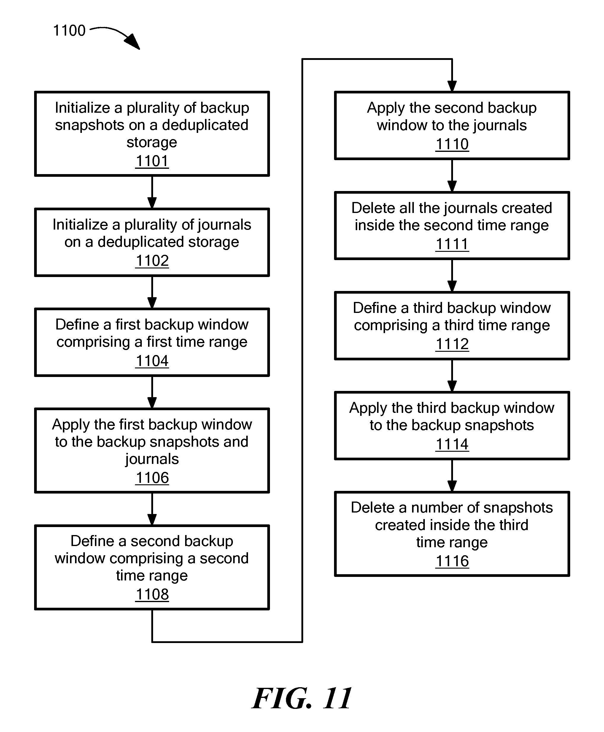
D00013

D00014

D00015

D00016

D00017
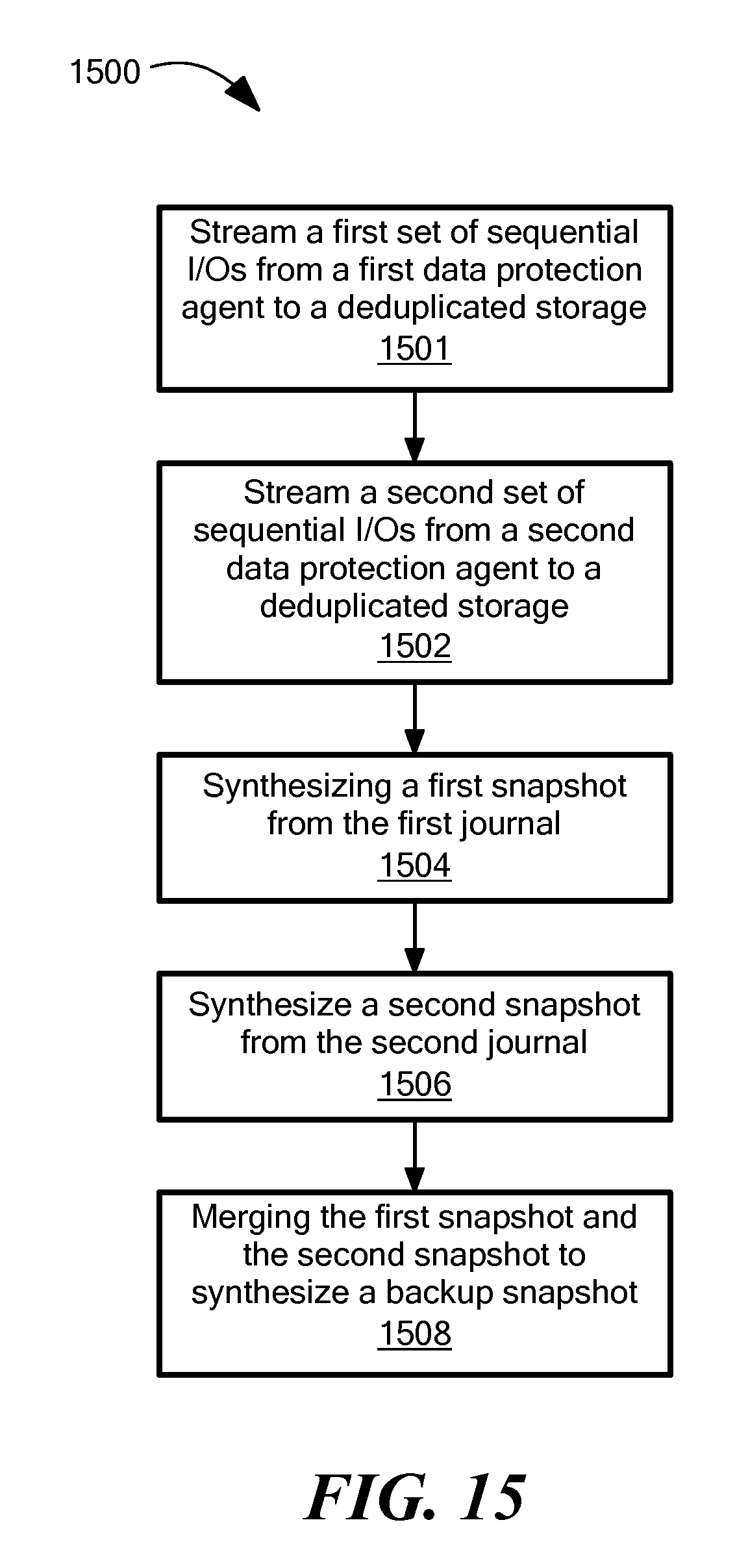
D00018
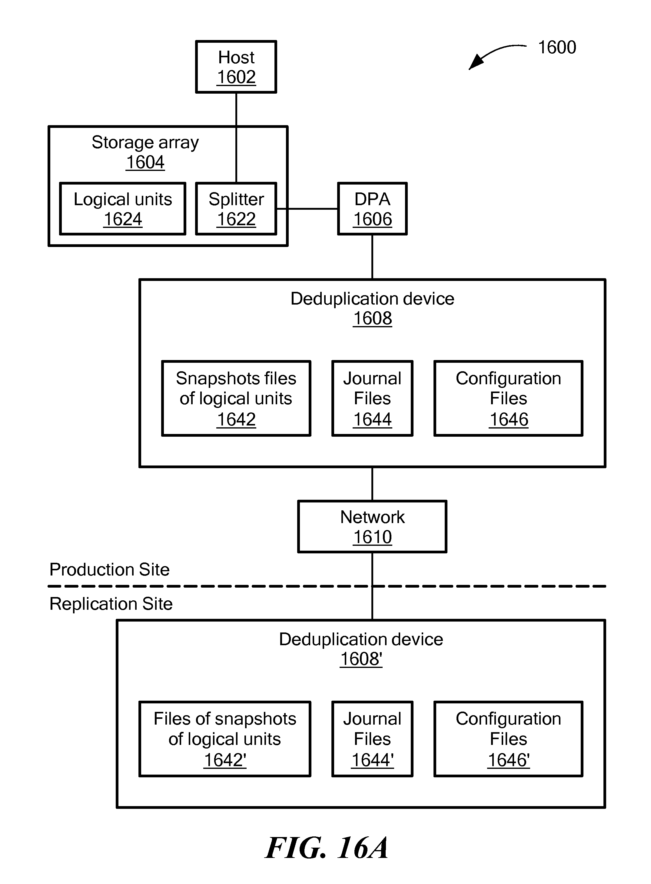
D00019

D00020

D00021

XML
uspto.report is an independent third-party trademark research tool that is not affiliated, endorsed, or sponsored by the United States Patent and Trademark Office (USPTO) or any other governmental organization. The information provided by uspto.report is based on publicly available data at the time of writing and is intended for informational purposes only.
While we strive to provide accurate and up-to-date information, we do not guarantee the accuracy, completeness, reliability, or suitability of the information displayed on this site. The use of this site is at your own risk. Any reliance you place on such information is therefore strictly at your own risk.
All official trademark data, including owner information, should be verified by visiting the official USPTO website at www.uspto.gov. This site is not intended to replace professional legal advice and should not be used as a substitute for consulting with a legal professional who is knowledgeable about trademark law.