Multi-pane dynamic window and method for making same
Egerton , et al. O
U.S. patent number 10,437,126 [Application Number 15/444,152] was granted by the patent office on 2019-10-08 for multi-pane dynamic window and method for making same. This patent grant is currently assigned to View, Inc.. The grantee listed for this patent is View, Inc.. Invention is credited to Peter Egerton, Drew Gaskell.


| United States Patent | 10,437,126 |
| Egerton , et al. | October 8, 2019 |
Multi-pane dynamic window and method for making same
Abstract
A window assembly comprises a plurality of dynamic electrochromic zones formed on a single transparent substrate in which at least two electrochromic zones are independently controllable. In one exemplary embodiment, the window assembly comprises an Insulated Glass Unit (IGU), and at least one transparent substrate comprises a lite. In another exemplary embodiment, the IGU comprises at least two lites in which at least one lite comprises a plurality of independently controllable dynamic zones.
| Inventors: | Egerton; Peter (Windsor, CA), Gaskell; Drew (Santa Rosa, CA) | ||||||||||
|---|---|---|---|---|---|---|---|---|---|---|---|
| Applicant: |
|
||||||||||
| Assignee: | View, Inc. (Milpitas,
CA) |
||||||||||
| Family ID: | 41445301 | ||||||||||
| Appl. No.: | 15/444,152 | ||||||||||
| Filed: | February 27, 2017 |
Prior Publication Data
| Document Identifier | Publication Date | |
|---|---|---|
| US 20170168367 A1 | Jun 15, 2017 | |
Related U.S. Patent Documents
| Application Number | Filing Date | Patent Number | Issue Date | ||
|---|---|---|---|---|---|
| 15130819 | Apr 15, 2016 | 9618819 | |||
| 14608452 | May 17, 2016 | 9341909 | |||
| 14266576 | Aug 18, 2015 | 9110345 | |||
| 13903905 | Jun 10, 2014 | 8749870 | |||
| 12145892 | Aug 20, 2013 | 8514476 | |||
| Current U.S. Class: | 1/1 |
| Current CPC Class: | E06B 3/66 (20130101); G02F 1/155 (20130101); G02F 1/163 (20130101); G02F 1/0126 (20130101); G02F 1/15 (20130101); G02B 5/23 (20130101); E06B 9/24 (20130101); G02F 1/153 (20130101); G02F 1/133308 (20130101); G02F 1/157 (20130101); G02F 1/13336 (20130101); E06B 3/6722 (20130101); G02F 1/1533 (20130101); G02F 1/0147 (20130101); G02F 2201/123 (20130101); E06B 2009/2417 (20130101); E06B 2009/2464 (20130101); G02F 2202/14 (20130101); E06B 2009/2405 (20130101); G02F 2203/01 (20130101); G02F 1/1508 (20130101) |
| Current International Class: | G02F 1/153 (20060101); G02F 1/01 (20060101); G02F 1/155 (20060101); G02F 1/163 (20060101); E06B 3/66 (20060101); G02F 1/1333 (20060101); E06B 9/24 (20060101); G02F 1/15 (20190101); E06B 3/67 (20060101); G02F 1/157 (20060101); G02B 5/23 (20060101) |
| Field of Search: | ;359/238-279 |
References Cited [Referenced By]
U.S. Patent Documents
| 4129861 | December 1978 | Giglia |
| 4832468 | May 1989 | Ito et al. |
| 4923289 | May 1990 | Demiryont |
| 5076673 | December 1991 | Lynam et al. |
| 5140455 | August 1992 | Varaprasad et al. |
| 5142407 | August 1992 | Varaprasad et al. |
| 5145609 | September 1992 | Varaprasad et al. |
| 5151816 | September 1992 | Varaprasad et al. |
| 5187607 | February 1993 | Endo et al. |
| 5233461 | August 1993 | Dornan et al. |
| 5239405 | August 1993 | Varaprasad et al. |
| 5340503 | August 1994 | Varaprasad et al. |
| 5379146 | January 1995 | Defendini |
| 5471338 | November 1995 | Yu et al. |
| 5472643 | December 1995 | Varaprasad et al. |
| 5500760 | March 1996 | Varaprasad et al. |
| 5567360 | October 1996 | Varaprasad et al. |
| 5657149 | August 1997 | Buffat et al. |
| 5657150 | August 1997 | Kallman et al. |
| 5668663 | September 1997 | Varaprasad et al. |
| 5724175 | March 1998 | Hichwa et al. |
| 5724176 | March 1998 | Nishikitani et al. |
| 5724187 | March 1998 | Varaprasad et al. |
| 5777603 | July 1998 | Jaeger |
| 5805330 | September 1998 | Byker et al. |
| 5814195 | September 1998 | Lehan et al. |
| 5830336 | November 1998 | Schulz |
| 5953150 | September 1999 | Smarto et al. |
| 5969847 | October 1999 | Coleman et al. |
| 5985184 | November 1999 | Lynam |
| 5995271 | November 1999 | Zieba et al. |
| 6001487 | December 1999 | Ladang et al. |
| 6002511 | December 1999 | Varaprasad et al. |
| 6039850 | March 2000 | Schulz |
| 6045643 | April 2000 | Byker et al. |
| 6045896 | April 2000 | Boire et al. |
| 6055088 | April 2000 | Fix et al. |
| 6055089 | April 2000 | Schulz et al. |
| 6074279 | June 2000 | Yoshimura et al. |
| 6094292 | July 2000 | Goldner et al. |
| 6118573 | September 2000 | Kubo et al. |
| 6143209 | November 2000 | Lynam |
| 6154306 | November 2000 | Varaprasad et al. |
| 6166849 | December 2000 | Coleman et al. |
| 6178034 | January 2001 | Allemand et al. |
| 6204953 | March 2001 | Zieba et al. |
| 6207083 | March 2001 | Varaprasad et al. |
| 6244716 | June 2001 | Steenwyk et al. |
| 6261641 | July 2001 | Zieba et al. |
| 6337758 | January 2002 | Beteille et al. |
| 6433913 | August 2002 | Bauer et al. |
| 6471360 | October 2002 | Rukavina et al. |
| 6493128 | December 2002 | Agrawal et al. |
| 6515787 | February 2003 | Westfall et al. |
| 6529308 | March 2003 | Beteille et al. |
| 6535126 | March 2003 | Lin et al. |
| 6559411 | May 2003 | Borgeson et al. |
| 6561460 | May 2003 | Rukavina et al. |
| 6639709 | October 2003 | Vincent et al. |
| 6749103 | June 2004 | Ivanov et al. |
| 6783099 | August 2004 | Rukavina et al. |
| 6795226 | September 2004 | Agrawal et al. |
| 6798556 | September 2004 | Tench et al. |
| 6822778 | November 2004 | Westfall et al. |
| 6853472 | February 2005 | Warner et al. |
| 6862125 | March 2005 | Warner et al. |
| 6906842 | June 2005 | Agrawal et al. |
| 6919530 | July 2005 | Borgeson et al. |
| 6937380 | August 2005 | Fanton et al. |
| 6995891 | February 2006 | Agrawal et al. |
| 6995892 | February 2006 | Fanton et al. |
| 7002720 | February 2006 | Beteille et al. |
| 7004592 | February 2006 | Varaprasad et al. |
| 7033655 | April 2006 | Beteille et al. |
| 7114643 | October 2006 | Ivanov et al. |
| 7130101 | October 2006 | Rukavina et al. |
| 7133181 | November 2006 | Greer |
| 7146703 | December 2006 | Ivanov |
| 7173750 | February 2007 | Rukavina |
| 7202987 | April 2007 | Varaprasad et al. |
| 7230748 | June 2007 | Giron et al. |
| 7248392 | July 2007 | Rukavina et al. |
| 7256923 | August 2007 | Liu et al. |
| 7277215 | October 2007 | Greer |
| 7300166 | November 2007 | Agrawal et al. |
| 7317106 | January 2008 | Warner et al. |
| 7324261 | January 2008 | Tonar et al. |
| 7333258 | February 2008 | Yang et al. |
| 7362491 | April 2008 | Busick et al. |
| 7372610 | May 2008 | Burdis et al. |
| 7450294 | November 2008 | Weidner |
| 7467741 | December 2008 | Wickersham, Jr. et al. |
| 7531101 | May 2009 | Beteille |
| 7649668 | January 2010 | Fanton et al. |
| 7710671 | May 2010 | Kwak et al. |
| 7719751 | May 2010 | Egerton et al. |
| 7724416 | May 2010 | Miller |
| 7869114 | January 2011 | Valentin et al. |
| 7894119 | February 2011 | Valentin et al. |
| 7929194 | April 2011 | Legois et al. |
| 7961375 | June 2011 | Phillips |
| 7990603 | August 2011 | Ash et al. |
| 8035882 | October 2011 | Fanton et al. |
| 8164818 | April 2012 | Collins et al. |
| 8213074 | July 2012 | Shrivastava et al. |
| 8270059 | September 2012 | Friedman et al. |
| 8514476 | August 2013 | Egerton et al. |
| 8749870 | June 2014 | Egerton et al. |
| 8780432 | July 2014 | Nguyen |
| 9110345 | August 2015 | Egerton et al. |
| 9341909 | May 2016 | Egerton et al. |
| 9341912 | May 2016 | Shrivastava et al. |
| 9618819 | April 2017 | Egerton et al. |
| 2002/0021481 | February 2002 | Lin et al. |
| 2002/0041443 | April 2002 | Varaprasad et al. |
| 2002/0075552 | June 2002 | Poll et al. |
| 2002/0135881 | September 2002 | Rukavina et al. |
| 2002/0149829 | October 2002 | Mochizuka et al. |
| 2003/0227663 | December 2003 | Agrawal et al. |
| 2004/0047050 | March 2004 | Bauer et al. |
| 2004/0150866 | August 2004 | Tench et al. |
| 2004/0257633 | December 2004 | Agrawal et al. |
| 2005/0002081 | January 2005 | Beteille et al. |
| 2005/0168793 | August 2005 | Fanton et al. |
| 2006/0077511 | April 2006 | Poll et al. |
| 2006/0187608 | August 2006 | Stark |
| 2007/0002420 | January 2007 | Rukavina |
| 2007/0002422 | January 2007 | O'Shaughnessy |
| 2007/0020442 | January 2007 | Giron et al. |
| 2007/0067048 | March 2007 | Bechtel et al. |
| 2007/0103761 | May 2007 | Giron et al. |
| 2007/0133078 | June 2007 | Fanton et al. |
| 2007/0268550 | November 2007 | Liu et al. |
| 2008/0042012 | February 2008 | Callahan et al. |
| 2008/0074724 | March 2008 | Agrawal et al. |
| 2008/0092456 | April 2008 | Millett et al. |
| 2008/0115428 | May 2008 | Schlam et al. |
| 2008/0204850 | August 2008 | Agrawal |
| 2009/0058295 | March 2009 | Auday et al. |
| 2009/0067031 | March 2009 | Piroux et al. |
| 2009/0097098 | April 2009 | Piroux |
| 2009/0110918 | April 2009 | Jacquiod et al. |
| 2009/0114928 | May 2009 | Messere et al. |
| 2009/0127126 | May 2009 | Torvund |
| 2009/0130409 | May 2009 | Reutler et al. |
| 2009/0148642 | June 2009 | Mauser et al. |
| 2009/0174300 | July 2009 | Jousse et al. |
| 2009/0181203 | July 2009 | Valentin et al. |
| 2009/0251758 | October 2009 | Valentin et al. |
| 2009/0262411 | October 2009 | Karmhag et al. |
| 2009/0297806 | December 2009 | Dawson-Elli et al. |
| 2009/0323155 | December 2009 | Phillips |
| 2009/0323160 | December 2009 | Egerton et al. |
| 2010/0067090 | March 2010 | Egerton et al. |
| 2010/0203296 | August 2010 | Tsai et al. |
| 2010/0208326 | August 2010 | Kwak et al. |
| 2010/0225988 | September 2010 | Kalkanoglu |
| 2010/0243427 | September 2010 | Kozlowski et al. |
| 2010/0311204 | December 2010 | Komin et al. |
| 2011/0043885 | February 2011 | Lamine et al. |
| 2011/0048614 | March 2011 | Veerasamy et al. |
| 2011/0051221 | March 2011 | Veerasamy |
| 2011/0059275 | March 2011 | Stark |
| 2011/0100709 | May 2011 | Wang et al. |
| 2011/0148218 | June 2011 | Rozbicki |
| 2011/0216389 | September 2011 | Piroux et al. |
| 2011/0260961 | October 2011 | Burdis |
| 2011/0266138 | November 2011 | Wang et al. |
| 2011/0267672 | November 2011 | Sbar et al. |
| 2011/0299149 | December 2011 | Park et al. |
| 2011/0304899 | December 2011 | Kwak et al. |
| 2012/0033287 | February 2012 | Friedman et al. |
| 2012/0069420 | March 2012 | Suzuki |
| 2012/0147449 | June 2012 | Bhatnagar et al. |
| 2012/0194895 | August 2012 | Podbelski et al. |
| 2012/0200908 | August 2012 | Bergh et al. |
| 2012/0239209 | September 2012 | Brown et al. |
| 2012/0300280 | November 2012 | Murphy et al. |
| 2012/0327499 | December 2012 | Parker et al. |
| 2013/0021659 | January 2013 | Friedman et al. |
| 2013/0201545 | August 2013 | Frey et al. |
| 2013/0222877 | August 2013 | Greer et al. |
| 2013/0222878 | August 2013 | Greer et al. |
| 2013/0258436 | October 2013 | Podbelski et al. |
| 2013/0271813 | October 2013 | Brown |
| 2013/0271814 | October 2013 | Brown |
| 2013/0271815 | October 2013 | Pradhan et al. |
| 2013/0301104 | November 2013 | Egerton et al. |
| 2014/0055443 | February 2014 | Threlkel et al. |
| 2014/0133005 | May 2014 | Sbar et al. |
| 2014/0177028 | June 2014 | Shrivastava et al. |
| 2014/0320947 | October 2014 | Egerton et al. |
| 2015/0060648 | March 2015 | Brown et al. |
| 2015/0077829 | March 2015 | Greer et al. |
| 2015/0092259 | April 2015 | Greer et al. |
| 2015/0177586 | June 2015 | Egerton et al. |
| 2015/0338713 | November 2015 | Brown |
| 2015/0362817 | December 2015 | Patterson et al. |
| 2015/0362818 | December 2015 | Greer |
| 2016/0154290 | June 2016 | Brown et al. |
| 2016/0251894 | September 2016 | Shrivastava et al. |
| 2016/0306249 | October 2016 | Egerton et al. |
| 2016/0363799 | December 2016 | West et al. |
| 2017/0130523 | May 2017 | Shrivastava et al. |
| 2018/0284555 | October 2018 | Klawuhn et al. |
| 2019/0230776 | July 2019 | Casey et al. |
| 2019/0242184 | August 2019 | Shrivastava et al. |
| 1537257 | Oct 2004 | CN | |||
| 102388340 | Mar 2012 | CN | |||
| 102006042538 | Mar 2008 | DE | |||
| 102014220818 | Apr 2016 | DE | |||
| 0356099 | Feb 1990 | EP | |||
| 0470867 | Feb 1992 | EP | |||
| 0851271 | Jul 1998 | EP | |||
| 0950568 | Oct 1999 | EP | |||
| 1012661 | Jun 2000 | EP | |||
| 1420287 | May 2004 | EP | |||
| 1484634 | Dec 2004 | EP | |||
| 2348357 | Jul 2011 | EP | |||
| 2815960 | Dec 2014 | EP | |||
| 2957159 | Sep 2011 | FR | |||
| 2190760 | Nov 1987 | GB | |||
| S55-153982 | Dec 1980 | JP | |||
| S61-082821 | May 1986 | JP | |||
| S61-176012 | Aug 1986 | JP | |||
| S61-190815 | Aug 1986 | JP | |||
| S61-171034 | Oct 1986 | JP | |||
| S61-229610 | Oct 1986 | JP | |||
| S62-019631 | Feb 1987 | JP | |||
| H01-270032 | Oct 1989 | JP | |||
| H02-176728 | Jul 1990 | JP | |||
| H02-308228 | Dec 1990 | JP | |||
| H05-173191 | Jul 1993 | JP | |||
| H07-139201 | May 1995 | JP | |||
| 2002-249346 | Sep 2002 | JP | |||
| 2003-146072 | May 2003 | JP | |||
| 2004-093873 | Mar 2004 | JP | |||
| 2004-531770 | Oct 2004 | JP | |||
| 2006-243485 | Sep 2006 | JP | |||
| 2007-248604 | Sep 2007 | JP | |||
| 2008-507000 | Mar 2008 | JP | |||
| WO1998/038547 | Sep 1998 | WO | |||
| WO1999/005566 | Feb 1999 | WO | |||
| WO2003/001290 | Jan 2003 | WO | |||
| WO03/012541 | Feb 2003 | WO | |||
| WO03/012541 | Feb 2003 | WO | |||
| WO2005/076061 | Aug 2005 | WO | |||
| WO2006/052067 | May 2006 | WO | |||
| WO2007/100921 | Sep 2007 | WO | |||
| WO2008/043951 | Apr 2008 | WO | |||
| WO2009/145876 | Dec 2009 | WO | |||
| WO2009/148861 | Dec 2009 | WO | |||
| WO2009/158510 | Dec 2009 | WO | |||
| WO2011/010067 | Jan 2011 | WO | |||
| WO2011/028253 | Mar 2011 | WO | |||
| WO2011/028254 | Mar 2011 | WO | |||
| WO2011/050291 | Apr 2011 | WO | |||
| WO2011/109688 | Sep 2011 | WO | |||
| WO2011/133294 | Oct 2011 | WO | |||
| WO2012/145155 | Oct 2012 | WO | |||
| WO2013/090209 | Jun 2013 | WO | |||
| WO2013/130781 | Sep 2013 | WO | |||
| WO2013/138535 | Sep 2013 | WO | |||
| WO2014/078429 | May 2014 | WO | |||
| WO2015/050946 | Apr 2015 | WO | |||
| WO2015/095615 | Jun 2015 | WO | |||
| WO2015/171886 | Nov 2015 | WO | |||
| WO2016/058695 | Apr 2016 | WO | |||
| WO2016/085964 | Jun 2016 | WO | |||
| WO2017/059362 | Apr 2017 | WO | |||
| WO2017/075472 | May 2017 | WO | |||
Other References
|
Preliminary Amendment for U.S. Appl. No. 15/039,370, filed Mar. 30, 2017. cited by applicant . U.S. Office Action dated Nov. 8, 2012 for U.S. Appl. No. 12/145,892. cited by applicant . U.S. Office Action dated May 25, 2012 for U.S. Appl. No. 12/145,892. cited by applicant . U.S. Office Action dated Feb. 3, 2011 for U.S. Appl. No. 12/145,892. cited by applicant . U.S. Office Action dated Aug. 19, 2010 for U.S. Appl. No. 12/145,892. cited by applicant . U.S. Notice of Allowance dated Feb. 25, 2013 for U.S. Appl. No. 12/145,892. cited by applicant . U.S. Office Action dated Oct. 3, 2013 for U.S. Appl. No. 13/903,905. cited by applicant . U.S. Notice of Allowance dated Apr. 14, 2014 for U.S. Appl. No. 13/903,905. cited by applicant . U.S. Office Action dated Aug. 11, 2014 for U.S. Appl. No. 14/266,576. cited by applicant . U.S. Final Office Action dated Jan. 22, 2015 for U.S. Appl. No. 14/266,576. cited by applicant . U.S. Notice of Allowance dated Apr. 30, 2015 for U.S. Appl. No. 14/266,576. cited by applicant . U.S. Office Action dated Jun. 5, 2015 for U.S. Appl. No. 14/137,644. cited by applicant . Notice of Allowance dated Jan. 14, 2016 for U.S. Appl. No. 14/137,644. cited by applicant . U.S. Office Action dated Jul. 2, 2015 for U.S. Appl. No. 14/608,452. cited by applicant . U.S. Notice of Allowance dated Jan. 15, 2016 for U.S. Appl. No. 14/608,452. cited by applicant . U.S. Notice of Allowance dated Nov. 30, 2016 for for U.S. Appl. No. 15/130,819. cited by applicant . U.S. Notice of Allowance dated Mar. 11, 2010 for U.S. Appl. No. 12/212,482. cited by applicant . U.S. Office Action dated Jun. 16, 2017 for U.S. Appl. No. 15/039,370. cited by applicant . U.S. Office Action dated Jul. 3, 2017 for U.S. Appl. No. 15/094,897. cited by applicant . CN Office Action dated Dec. 5, 2012 in CN200980124126.7. cited by applicant . CN Office Action dated Sep. 4, 2013 in CN200980124126.7. cited by applicant . CN Office Action dated Apr. 18, 2016 in CN Application No. 201380059263.3. cited by applicant . CN Office Action dated Dec. 14, 2016 in CN Application No. 201380059263.3. cited by applicant . EP Search Report dated Mar. 20, 2012 in EP09771042.0. cited by applicant . EP Search Report dated Jun. 25, 2015 in EP09815048.5. cited by applicant . EP Search Report dated Sep. 23, 2015 in EP15160755.3. cited by applicant . Partial EP Search Report dated May 20, 2016 in EP13855151.0. cited by applicant . Extended EP Search Report dated Jul. 13, 2016 in EP13855151.0. cited by applicant . International Preliminary Report on Patentability dated Jan. 13, 2011 in PCT/US2009/048679. cited by applicant . International Search Report and Written Opinion dated Feb. 17, 2010 in PCT/US2009/048679. cited by applicant . International Preliminary Report on Patentability dated Mar. 22, 2011 in PCT/US2009/56928. cited by applicant . International Search Report and Written Opinion dated May 4, 2010 in PCT/US2009/56928. cited by applicant . International Preliminary Report on Patentability dated May 28, 2015 in PCT/US2013/069913. cited by applicant . International Search Report and Written Opinion dated Feb. 18, 2014 in PCT/US2013/069913. cited by applicant . International Search Report and Written Opinion dated Dec. 13, 2016 in PCT/US16/55005. cited by applicant . International Search Report dated Mar. 17, 2015 in PCT/US2014/071314. cited by applicant . JP Office Action dated Oct. 9, 2012 for JP2011-516666. cited by applicant . JP Office Action dated Apr. 5, 2013 in JP2011-516666. cited by applicant . CN Office Action dated Jun. 26, 2017 in CN201380059263.3. cited by applicant . EP Extended Search Report dated Jun. 21, 2017 in EP14872953.6. cited by applicant . E.S. Lee et al., Advancement of Electrochromic Windows. California Energy Commission, PIER. Publication No. CEC-500-2006-052, Apr. 2006. cited by applicant . Tseng, C-Y et al., "Improved performance mechanism of III-V compound triple-junction solar cell using hybrid electrode structure," Solar Energy, vol. 89, Jan. 19, 2013, pp. 17-22. cited by applicant . U.S. Final Office Action dated Dec. 29, 2017 for U.S. Appl. No. 15/039,370. cited by applicant . EP Intention to Grant & Annex with Complementary Search dated Apr. 19, 2018 in EP09815048.5. cited by applicant . International Preliminary Report on Patentability dated Apr. 12, 2018 in PCT/US16/55005. cited by applicant . International Preliminary Report on Patentability dated Jun. 30, 2016 in PCT/US2014/071314. cited by applicant . U.S. Appl. No. 15/762,077, filed Mar. 21, 2018, Klawuhn et al. cited by applicant . U.S. Office Action dated Oct. 19, 2018 for U.S. Appl. No. 15/039,370. cited by applicant . U.S. Final Office Action dated May 3, 2018 for U.S. Appl. No. 15/094,897. cited by applicant . U.S. Appl. No. 16/191,138, filed Nov. 14, 2018, Shrivastava et al. cited by applicant . U.S. Preliminary Amendment dated Nov. 19, 2018 in U.S. Appl. No. 16/191,138. cited by applicant. |
Primary Examiner: Sahle; Mahidere S
Attorney, Agent or Firm: Weaver Austin Villeneuve & Sampson LLP Griedel; Brian D.
Parent Case Text
CROSS REFERENCE TO RELATED APPLICATION
This application is a continuation of U.S. patent application Ser. No. 15/130,819, filed on Apr. 15, 2016 and titled "MULTI-PANE DYNAMIC WINDOW AND METHOD FOR MAKING SAME," which is a continuation of U.S. patent application Ser. No. 14/608,452, filed on Jan. 29, 2015 and titled "MULTI-PANE DYNAMIC WINDOW AND METHOD FOR MAKING SAME," now U.S. Pat. No. 9,341,909, which is a continuation of U.S. patent application Ser. No. 14/266,576, filed on Apr. 30, 2014 and titled "MULTI-PANE DYNAMIC WINDOW AND METHOD FOR MAKING SAME," now U.S. Pat. No. 9,110,345, which is a continuation of U.S. patent application Ser. No. 13/903,905, filed on May 28, 2013 and titled "MULTI-PANE DYNAMIC WINDOW AND METHOD FOR MAKING SAME," now U.S. Pat. No. 8,749,870, which is a continuation of U.S. patent application Ser. No. 12/145,892, filed on Jun. 25, 2008 and titled "MULTI-PANE DYNAMIC WINDOW AND METHOD FOR MAKING SAME," now U.S. Pat. No. 8,514,476, each of these applications is hereby incorporated by reference in their entirety and for all purposes.
Claims
What is claimed is:
1. A multi-zone dynamic window, comprising: a first transparent or translucent substrate; and a plurality of dynamic zones on the first substrate, the plurality of dynamic zones configured for independent control of optical transmittance properties, wherein at least one of the plurality of dynamic zones comprises a photochromic coating or a thermochromic coating disposed on the first substrate and at least one of the plurality of dynamic zones comprises a solid-state electrochromic device coating on the first substrate.
2. The multi-zone dynamic window of claim 1, wherein the photochromic coating comprises a material selected from the group consisting of a triarylmethane, a stilbene, an azastilbene, a nitrone, a fulgide, a spiropyran, a naphthopyran, a spiro-oxazine, and a quinone.
3. The multi-zone dynamic window of claim 1, wherein the thermochromic coating comprises a material is selected from the group consisting of a liquid crystal and a leuco dye.
4. The multi-zone dynamic window of claim 1, wherein the first substrate comprises at least one of glass, acrylic and polycarbonate.
5. The multi-zone dynamic window of claim 1, wherein said at least one of the plurality of dynamic zones comprising the electrochromic coating is located toward the top of the multi-zone dynamic window when installed, the dynamic zone configured for active control of transmittance properties for daylighting and/or reducing glare.
6. The multi-zone dynamic window of claim 5, further comprising a pair of bus bars on the first substrate, the bus bars configured to apply a voltage to the electrochromic coating to control transmittance properties through the dynamic zone independently of the modulation of transmittance properties through other dynamic zones of the plurality of dynamic zones.
7. The multi-zone dynamic window of claim 5, further comprising an electrically isolating line of removed material between said at least one of the plurality of dynamic zones comprising the electrochromic coating and other dynamic zones of the plurality of dynamic zones.
8. The multi-zone dynamic window of claim 7, wherein the electrically isolating line has a width of between about 10 .mu.m and 100 .mu.m.
9. The multi-zone dynamic window of claim 1, wherein the plurality of dynamic zones are configured for independent control of transmittance properties based on one or more of internal light levels, external light levels, weather conditions, time of day, and time of year.
10. The multi-zone dynamic window of claim 1, further comprising a frame, wherein the first substrate is located in the frame configured for installation in a sash or a curtain wall.
11. The multi-zone dynamic window of claim 1, wherein the first substrate is part of an insulated glass unit (IGU).
12. An insulated glass unit (IGU) comprising: a pair of parallel lites; a spacer between the parallel lites; and a seal between each of the parallel lites and the spacer; wherein at least one lite has a plurality of dynamic zones, wherein at least one of the plurality of dynamic zones comprises a photochromic coating or a thermochromic coating disposed on the at least one lite and at least one of the plurality of dynamic zones comprises a solid-state electrochromic device coating on the at least one lite.
13. The IGU of claim 12, wherein each of the plurality of dynamic zones is an isolated area of the at least one lite.
14. The IGU of claim 12, wherein the plurality of dynamic zones is configured for independent control of transmittance properties.
15. The IGU of claim 12, wherein the photochromic coating comprises a material selected from the group consisting of a triarylmethane, a stilbene, an azastilbene, a nitrone, a fulgide, a spiropyran, a naphthopyran, a spiro-oxazine, and a quinone.
16. The IGU of claim 12, wherein the thermochromic coating comprises a material is selected from the group consisting of a liquid crystal and a leuco dye.
17. The IGU of claim 12, wherein one or both of the lites comprise at least one of glass, acrylic and polycarbonate.
18. The IGU of claim 12, further comprising a pair of bus bars on the first substrate, the bus bars configured to apply a voltage to the electrochromic coating to control transmittance properties through the dynamic zone independently of the modulation of transmittance properties through other dynamic zones of the plurality of dynamic zones.
19. The IGU of claim 12, further comprising an electrically isolating line of removed material between said at least one of the plurality of dynamic zones comprising the electrochromic coating and other dynamic zones of the plurality of dynamic zones.
20. The IGU of claim 19, wherein the electrically isolating line has a width of between about 10 .mu.m and 100 .mu.m.
21. The IGU of claim 12, wherein the plurality of dynamic zones is configured for independent control of transmittance properties based on one or more of internal light levels, external light levels, weather conditions, time of day, and time of year.
22. The IGU of claim 12, wherein the electrochromic coating comprises a sputtered layer.
23. The IGU of claim 12, wherein the electrochromic coating comprises a sol gel layer.
24. The IGU of claim 12, further comprising a low-E coating or a reflective coating on at least one of the pair of parallel lites.
25. The IGU of claim 12, wherein the at least one lite of the pair of parallel lites comprises a light scattering feature.
Description
BACKGROUND
The subject matter disclosed herein relates to dynamic windows, such as smart windows. More particularly, the subject matter disclosed herein relates to dynamic multi-pane Insulated Glass Units (IGUs) in which at least one pane comprises a plurality of independently controllable dynamic zones.
BRIEF DESCRIPTION OF THE DRAWINGS
The subject matter disclosed herein is illustrated by way of example and not by limitation in the accompanying figures in which like reference numerals indicate similar elements and in which:
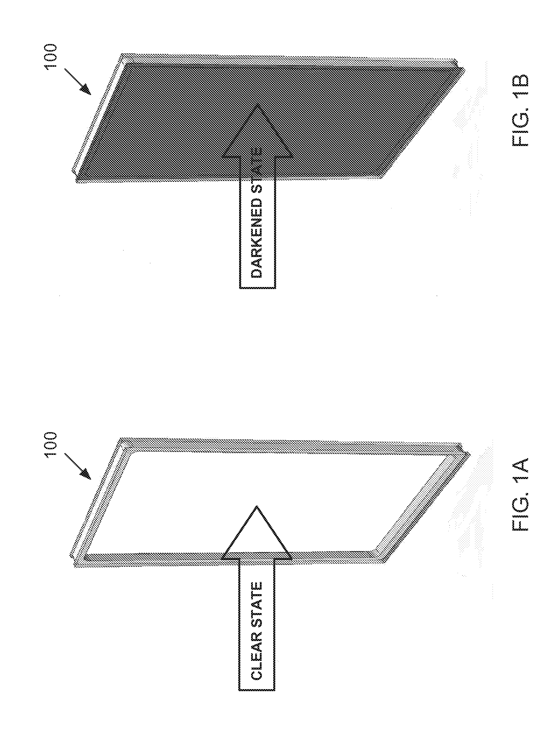
FIGS. 1A and 1B depict a conventional dynamic IGU that utilizes a dynamic coating in a well-known manner to change the visible transmittance through the IGU;
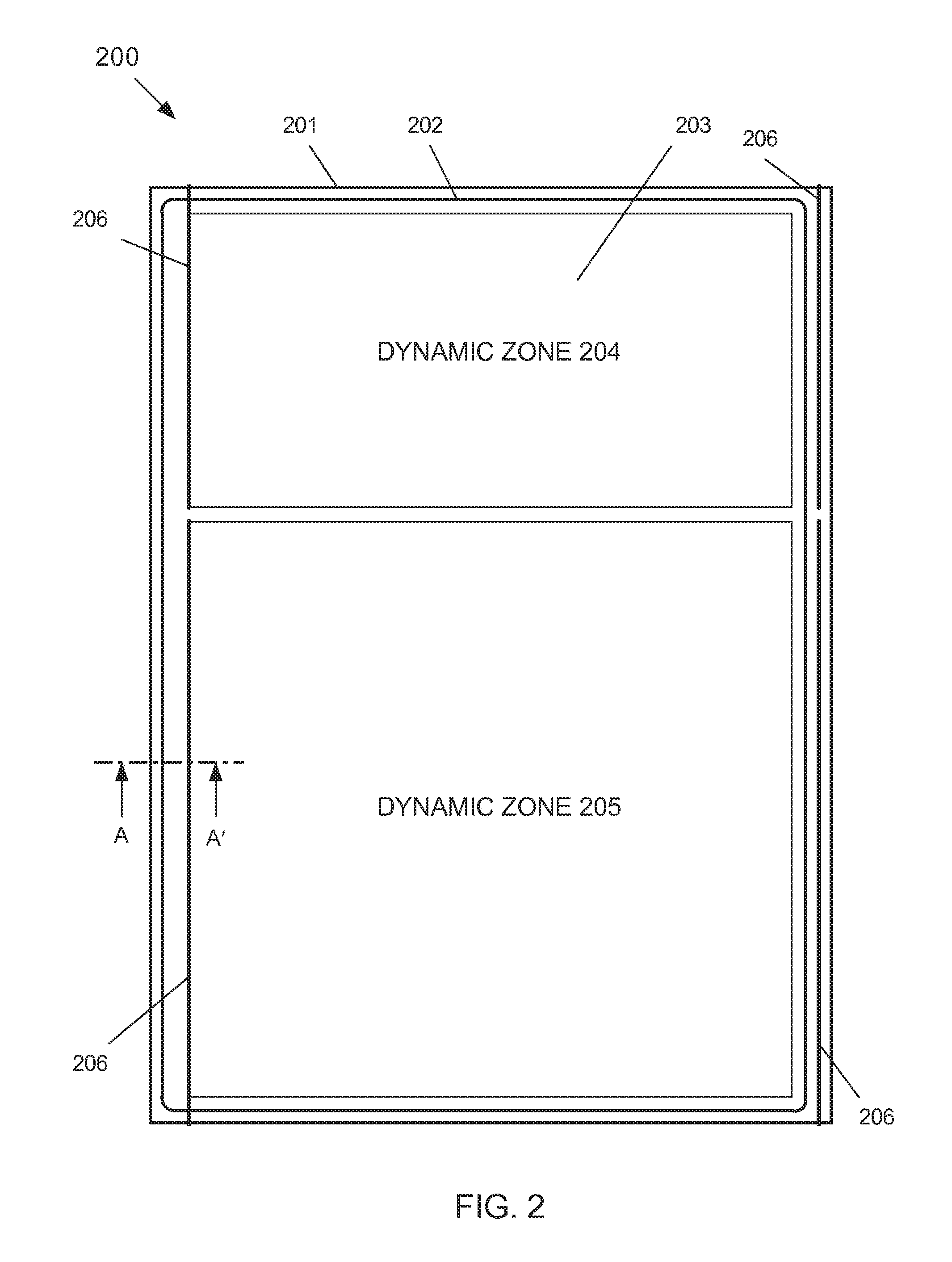
FIG. 2 depicts one exemplary embodiment of a multi-pane IGU having multiple dynamic zones according to the subject matter disclosed herein;
FIG. 3 depicts a cross-sectional view A-A' (shown in FIG. 2) of a portion of multi-pane IGU according to the subject matter disclosed herein; and
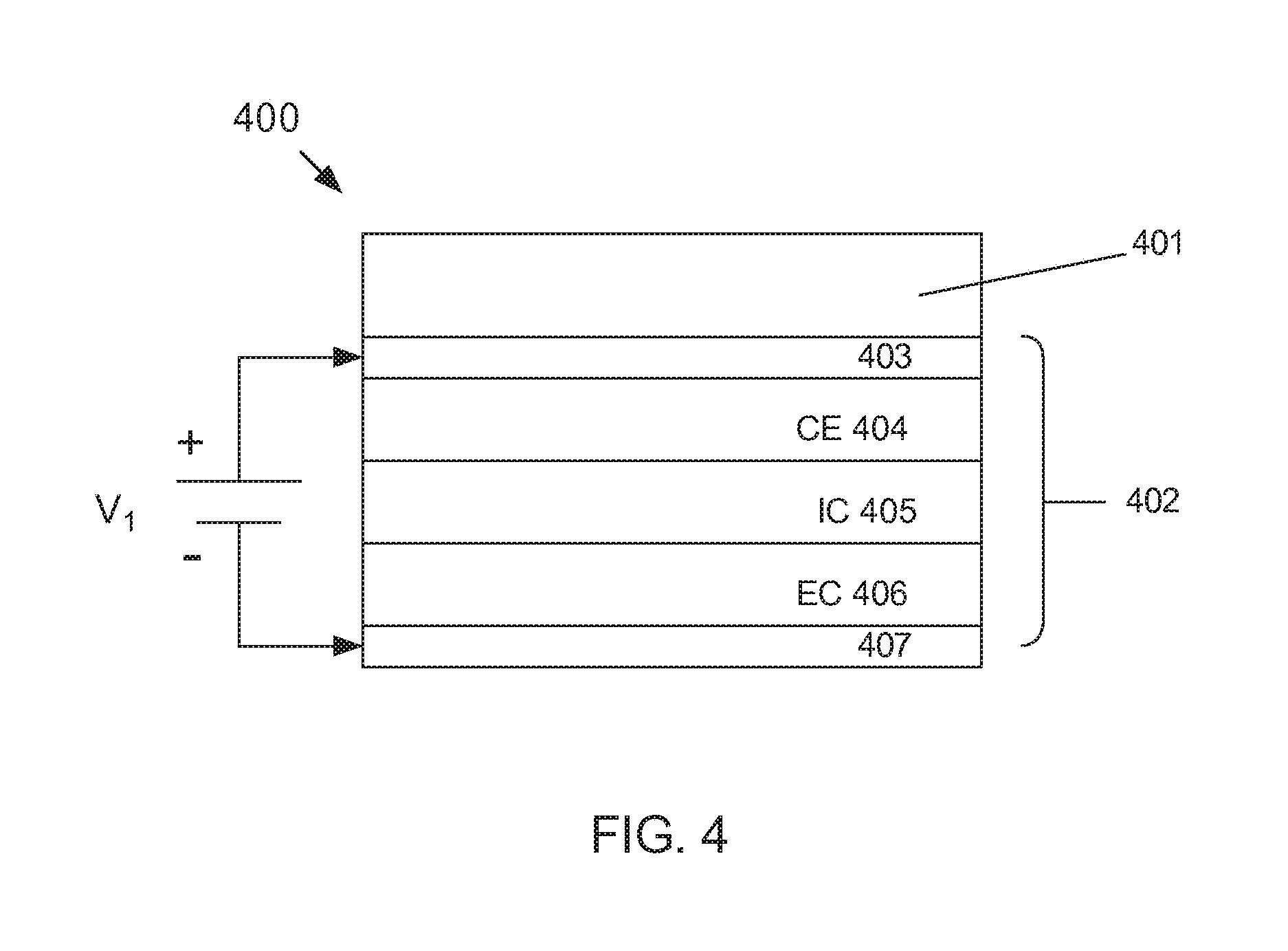
FIG. 4 depicts a sectional view of a first exemplary embodiment of a solid-state electrochromic device that is suitable for a dynamic zone according to the subject matter disclosed herein.
DETAILED DESCRIPTION
The word "exemplary" is used herein to mean "serving as an example, instance, or illustration." Any embodiment described herein as "exemplary" is not to be construed as necessarily preferred or advantageous over other embodiments.
The subject matter disclosed herein relates to multi-pane Insulated Glass Units (IGUs) comprising at least one pane, or lite, having a dynamic (i.e., a variable visible transmittance (Tvis) and/or variable Solar Heat Gain Coefficient (SHGC)) coating on a surface of the pane that provides at least two, independently controllable dynamic zones.
FIGS. 1A and 1B depict a conventional dynamic IGU 100 that utilizes a dynamic coating in a well-known manner to change the visible transmittance through the IGU. In particular, FIG. 1A depicts conventional dynamic IGU 100 in a clear state, and FIG. 1B depicts conventional dynamic IGU 100 in a darkened state.
Masking has been one conventional approach that has been tried for making a dynamic IGU that has multiple independently controllable zones. Masking, nevertheless, includes the problems of producing short circuits that require elimination and of producing visual defects in the isolation area between two independently controlled dynamic zones. Other techniques that have been tried include difficult manufacturing techniques that significantly increase the production costs associated with such IGUs. Thus, conventional practical sealed IGUs have been restricted to either a single dynamic zone or several separately glazed IGUs, each having a single dynamic zone, formed together into a single IGU assembly.
Multi-zone, dynamic windows according to the subject matter disclosed herein provide many advantages over conventional dynamic IGUs, such as permitting optimized harvesting of natural daylight through one or more dynamic zones, while being able to maximize solar-control advantages in the other dynamic zones of the window. Different dynamic zones can be created at any arbitrary distance from the edge of a window in order to satisfy diverse design goals and requirements.
FIG. 2 depicts one exemplary embodiment of a multi-pane IGU 200 having multiple dynamic zones according to the subject matter disclosed herein. IGU 200 comprises an IGU frame 201, a seal 202, at least two window panes (or lites) 203. IGU frame 201 holds and supports each window pane 203 in a well-known manner. The space between window panes 203 is sealed by seal 202 in a well-known manner so that the space can be filled in a well-known manner with air and/or an inert gas, such as argon, krypton and/or xenon. Alternatively, the space between the window panes can be evacuated so that the space contains a partial vacuum.
At least one window pane 203 of IGU 200 comprises a first dynamic zone 204 and a second dynamic zone 205. In one exemplary embodiment dynamic zones 204 and 205 are electrochromic dynamic zones. In another exemplary embodiment, at least one dynamic zone could be a photochromic or a thermochromic dynamic zone. Bus bars 206 are coupled to each dynamic zone in a well-known manner in order to independently apply control voltages to each respective dynamic zone. Bus bars 206 are made electrically available at the outside edge of frame 201. Each respective dynamic zone can be independently controlled in a well-known manner based on, for example, internal and/or external light levels, internal and/or external weather conditions, the time of day, the time of year, etc.
FIG. 3 depicts a cross-sectional view A-A' (shown in FIG. 2) of a portion of multi-pane IGU 200 according to the subject matter disclosed herein. As shown in FIG. 3, multi-pane IGU 200 comprises a first lite 203a, a second lite 203b, a spacer 211, a first seal 212, and a second seal 213. (Frame 201 is not depicted in FIG. 3.) First and second lites 203a and 203b can be formed from, for example, glass, acrylic and/or polycarbonate. One or both lites 203a and 203b can be transparent or be translucent.
Alternatively, a portion of one or both lites 203a and 203b can be transparent or be translucent. Spacer 211 is positioned in a well-known manner between first lite 203a and second lite 203b to form space 214. In one exemplary embodiment, spacer 211 forms a gap (or space) between first lite 203a and second lite 203b of about 12 mm to about 20 mm. First seal 212, such as a silicon-based seal, and second seal 213, such as a butyl-based seal, form seal 202 (FIG. 2) and hermetically seals space 214 in a well-known manner. Other sealing materials can alternatively or additionally be used. A desiccant (not shown) can, for example, be placed within spacer 211 in a well-known manner for preventing condensation and improving insulating performance of IGU 200.
FIG. 3 also depicts a bus bar 206 and dynamic coating 220 that have been formed on lite 203b. In one exemplary embodiment, dynamic coating 220 is an electrochromic-based coating that forms a dynamic zone. According to the subject matter disclosed herein, both bus bar 206 and dynamic coating 220 are formed across a desired area on lite 203b. A laser scribing and/or ablation process is then used to form very thin, highly isolating lines between desired dynamic zones. The bus bars that are coupled to each respective dynamic zone are made electrically available in a well-known manner through the frame of the IGU. Because each dynamic zone is isolated from other dynamic zones of the IGU, each dynamic zone can be independently controlled to vary the transmittance through the zone.
Several exemplary techniques for forming the layers of an electrochromic dynamic zone in a well-known manner generally comprise physical vapor deposition, sputtering, pyrolytic-coating techniques, wet-chemical techniques, such as a sol gel process, spin-coating techniques, and vacuum-coating techniques.
Bus bars 206 can be formed on substrate 201 prior to forming any dynamic coatings. Alternatively, bus bars 206 can be ultrasonically soldered on to substrate 201 following deposition of the dynamic zones or at an intermediate time during the deposition process. The bus bars are arranged on substrate 201 using form factors that are based on the size and shape of the desired dynamic zones. When the bus bars are formed separately for each dynamic zone, and the dynamic zone is formed as one large zone, laser ablation can be used for separating and isolating one dynamic zone from another dynamic zone. Alternatively, the bus bars may be created along the entire length of an IGU, such as depicted in FIG. 2. For this alternative technique, the laser would be used to ablate and isolate both the dynamic coating zones and the bus bars into distinct dynamic zones. When using this alternative technique, care must be taken for the removal of bus bar material ejected during ablation. Separation lines formed by laser ablation, in general, have a desired narrow width (i.e., between about 10 .mu.m and 100 .mu.m), have a clean edge that provides excellent electrical isolation characteristics between dynamic zones and between bus bars. Alternatively, ablation lines have a width greater than 100 .mu.m can also be used. Lasers that are suitable for producing the ablation lines include solid-state lasers, such as Nd:YAG at a wavelength of 1064 nm, and excimer lasers, such as ArF and KrF excimer lasers respectively emitting at 248 nm and 193 nm. Other solid-state and excimer lasers are also suitable.
FIG. 4 depicts a sectional view of a first exemplary embodiment of a solid-state electrochromic device 400 that is suitable for a dynamic zone according to the subject matter disclosed herein. Electrochromic device 400 comprises a substrate layer 401 (i.e., lite 203) and a solid-state electrochromic cell 402. Electrochromic cell 402 comprises a transparent conductive layer 403, a counter electrode (CE) layer 404 (anode), an ion conductor (IC) layer 405, an electrochromic (EC) layer 406 (cathode), and a transparent conductive layer 407. Voltage V.sub.1 is applied between conductive layer 403 and conductive layer 407 to control the transmittance of cell 402 in a well-known manner. Different voltages can be independently applied to the different cells for the different dynamic zones of an IGU.
Cell 402 can be vacuum deposited in a continuous fashion onto substrate 401. Any deposition method may be used, i.e., electron beam, AC sputtering, DC sputtering or CVD for deposition of the various layers of cell 402. Another exemplary solid-state electrochromic device that is suitable for a dynamic zone is a multi-cell solid-state electrochromic device that is disclosed in U.S. patent application Ser. No. 12/145,846 (now U.S. Pat. No. 7,961,375), entitled "Multi-cell Solid-state Electrochromic Device," invented by Roger Phillips, the disclosure of which is incorporated by reference herein.
Photochromic and thermochromic materials could be used one or more dynamic zones. Suitable photochromic materials include, but are not limited to, triarylmethanes, stilbenes, azastilbenes, nitrones, fulgides, spriropyrans, naphthopyrans, sprio-oxazines, and quinones. Suitable thermochromic materials include, but are not limited to, liquid crystals and leuco dyes. Both photochromic and thermochromic materials can be formed on substrate 201 (FIG. 2) in a well-known manner. No bus bars would be needed for photochromic or thermochromic dynamic zones because light and heat respectively modulate the properties of the materials. One exemplary embodiment using photochromic and/or thermochromic dynamic zones could be a window having at least one electrochromic dynamic zone towards the top of the window that is actively controlled for daylighting and at least one photochromic dynamic zone towards the bottom of the window that self darkens when under direct light.
While only two dynamic zones 204 and 205 are depicted in FIG. 2, it should be understood that any number of dynamic zones can be used. Moreover, while dynamic zones 204 and 205 are depicted as having a generally rectangular shape, the subject matter disclosed herein provides that a plurality of dynamic zones, each having a selected shape, can be used. Further still, while multi-pane IGU 200 is depicted as having a generally rectangular shape, the subject matter disclosed herein provides that a multi-pane IGU of any selected size and shape can be used.
Further, it should be understood that one exemplary embodiment of the subject matter disclosed herein can comprise a window having a single pane, or lite, that comprises a plurality of independently controlled dynamic zones. Another exemplary embodiment of the subject matter disclosed herein comprises an IGU comprising multiple zones of electrochromic window on one pane and clear glass on the other pane. Yet another exemplary embodiment of the subject matter disclosed herein comprises an IGU comprising multiple zones of electrochromic window on one pane and a low-E, tinted, or reflective glass on the other pane. Still another exemplary embodiment of the subject matter disclosed herein comprises an IGU comprising multiple zones of electrochromic window on one pane of the IGU and a patterned or special glass on the other pane in which the patterning or features may match, compliment, and/or contrast the areas of dynamic zones on the first pane. It should be understood that the foregoing exemplary embodiments can be configured so that the lite comprising the plurality of dynamic zones is a clear lite, a low-E lite, a reflective, and/or partially reflective lite.
Moreover, patterning of a lite and/or the characteristics of the lite can accentuate the functions of each dynamic zone in a window. For example, silk screening and/or added scattering features can be added on the opposite pane (i.e., not the pane comprising dynamic zones) corresponding to at least one dynamic zone, for example, for light harvesting in order to improve the effects of daylighting and/or for reducing glare issues. Yet other exemplary embodiments of the subject matter disclosed herein include a window pane comprising a plurality of independently controllable dynamic zones that has been glazed in a frame in a sash or a curtain wall.
Although the foregoing disclosed subject matter has been described in some detail for purposes of clarity of understanding, it will be apparent that certain changes and modifications may be practiced that are within the scope of the appended claims. Accordingly, the present embodiments are to be considered as illustrative and not restrictive, and the subject matter disclosed herein is not to be limited to the details given herein, but may be modified within the scope and equivalents of the appended claims.
* * * * *
D00000
D00001
D00002
D00003
D00004
XML
uspto.report is an independent third-party trademark research tool that is not affiliated, endorsed, or sponsored by the United States Patent and Trademark Office (USPTO) or any other governmental organization. The information provided by uspto.report is based on publicly available data at the time of writing and is intended for informational purposes only.
While we strive to provide accurate and up-to-date information, we do not guarantee the accuracy, completeness, reliability, or suitability of the information displayed on this site. The use of this site is at your own risk. Any reliance you place on such information is therefore strictly at your own risk.
All official trademark data, including owner information, should be verified by visiting the official USPTO website at www.uspto.gov. This site is not intended to replace professional legal advice and should not be used as a substitute for consulting with a legal professional who is knowledgeable about trademark law.