Economizer controller plug and play system recognition with automatic user interface population
Grabinger , et al. O
U.S. patent number 10,429,861 [Application Number 15/585,056] was granted by the patent office on 2019-10-01 for economizer controller plug and play system recognition with automatic user interface population. This patent grant is currently assigned to Honeywell International Inc.. The grantee listed for this patent is Honeywell International Inc.. Invention is credited to Cory Grabinger, Todd Kreft, Miroslav Mikulica, Adrienne Thomle.


| United States Patent | 10,429,861 |
| Grabinger , et al. | October 1, 2019 |
Economizer controller plug and play system recognition with automatic user interface population
Abstract
An economizer controller system having a plug and play recognition approach with an automatic user interface population mechanism. A check may be made for sensors connected to the controller. The control type of the sensors may be determined. The menu structure may be repopulated based on the control type. The user interface may then be updated. This approach may be repeated as needed.
| Inventors: | Grabinger; Cory (Maple Grove, MN), Mikulica; Miroslav (Brno, CZ), Kreft; Todd (Richfield, MN), Thomle; Adrienne (Plymouth, MN) | ||||||||||
|---|---|---|---|---|---|---|---|---|---|---|---|
| Applicant: |
|
||||||||||
| Assignee: | Honeywell International Inc.
(Morris Plains, NJ) |
||||||||||
| Family ID: | 45871989 | ||||||||||
| Appl. No.: | 15/585,056 | ||||||||||
| Filed: | May 2, 2017 |
Prior Publication Data
| Document Identifier | Publication Date | |
|---|---|---|
| US 20170336814 A1 | Nov 23, 2017 | |
Related U.S. Patent Documents
| Application Number | Filing Date | Patent Number | Issue Date | ||
|---|---|---|---|---|---|
| 14262237 | Apr 25, 2014 | 9703299 | |||
| 12890396 | May 6, 2014 | 8719720 | |||
| Current U.S. Class: | 1/1 |
| Current CPC Class: | F24F 11/30 (20180101); G05D 23/1917 (20130101); Y02B 30/542 (20130101) |
| Current International Class: | G05D 23/19 (20060101); F24F 11/30 (20180101) |
References Cited [Referenced By]
U.S. Patent Documents
| 3979922 | September 1976 | Shavit |
| 4182180 | January 1980 | Mott |
| 4267967 | May 1981 | Beck et al. |
| 4347712 | September 1982 | Benton et al. |
| 4379484 | April 1983 | Lom et al. |
| 4389853 | June 1983 | Hile |
| 4415896 | November 1983 | Allgood |
| 4423364 | December 1983 | Kompelien et al. |
| 4495986 | January 1985 | Clark et al. |
| 4497031 | January 1985 | Froehling et al. |
| 4543796 | October 1985 | Han et al. |
| 4570448 | February 1986 | Smith |
| 4580620 | April 1986 | Fukumoto et al. |
| 4591093 | May 1986 | Elliot, Jr. |
| 4605160 | August 1986 | Day |
| 4646964 | March 1987 | Parker et al. |
| 4838484 | June 1989 | Kreuter |
| 4843084 | June 1989 | Parker et al. |
| 4884214 | November 1989 | Parker et al. |
| 4931948 | June 1990 | Parker et al. |
| 4933633 | June 1990 | Allgood |
| 5103391 | April 1992 | Barrett |
| 5165465 | November 1992 | Kenet |
| 5276630 | January 1994 | Baldwin et al. |
| 5292280 | March 1994 | Janu et al. |
| 5311451 | May 1994 | Barrett |
| 5385297 | January 1995 | Rein et al. |
| 5390206 | February 1995 | Rein et al. |
| 5418131 | May 1995 | Butts |
| 5446677 | August 1995 | Jensen et al. |
| 5535814 | July 1996 | Hartman |
| 5564626 | October 1996 | Kettler et al. |
| 5590830 | January 1997 | Kettler et al. |
| 5597354 | January 1997 | Janu et al. |
| 5602758 | February 1997 | Lincoln et al. |
| 5605280 | February 1997 | Hartman |
| 5706190 | January 1998 | Russ et al. |
| 5719408 | February 1998 | Yamamoto et al. |
| 5762420 | June 1998 | Mills |
| 5772501 | June 1998 | Merry et al. |
| 5791408 | August 1998 | Seem |
| 5801940 | September 1998 | Russ et al. |
| 5874736 | February 1999 | Pompei |
| 5970430 | October 1999 | Burns et al. |
| 6006142 | December 1999 | Seem et al. |
| 6026352 | February 2000 | Burns et al. |
| 6125540 | October 2000 | Court et al. |
| 6126540 | October 2000 | Janu et al. |
| 6161764 | December 2000 | Jatnieks |
| 6223544 | May 2001 | Seem |
| 6249100 | June 2001 | Lange |
| 6250382 | June 2001 | Rayburn et al. |
| 6415617 | July 2002 | Seem |
| 6487457 | November 2002 | Hull et al. |
| 6488081 | December 2002 | Rayburn et al. |
| 6491094 | December 2002 | Rayburn et al. |
| 6514138 | February 2003 | Estepp |
| 6578770 | June 2003 | Rosen |
| 6581847 | June 2003 | Kline et al. |
| 6608558 | August 2003 | Sen et al. |
| 6609967 | August 2003 | Sharp et al. |
| 6629886 | October 2003 | Estepp |
| 6634422 | October 2003 | Rayburn et al. |
| 6640162 | October 2003 | Swanson |
| 6756998 | June 2004 | Bilger |
| 6778945 | August 2004 | Chassin et al. |
| 6792319 | September 2004 | Bilger |
| 6792767 | September 2004 | Pargeter et al. |
| 6826920 | December 2004 | Wacker |
| 6851621 | February 2005 | Wacker et al. |
| 6916239 | July 2005 | Siddaramanna et al. |
| 6988671 | January 2006 | DeLuca |
| 7036559 | May 2006 | Stanimirovic |
| 7044397 | May 2006 | Bartlett et al. |
| 7055759 | June 2006 | Wacker et al. |
| 7059536 | June 2006 | Schneider et al. |
| 7099748 | August 2006 | Rayburn et al. |
| 7104460 | September 2006 | Masen et al. |
| 7106460 | September 2006 | Haines et al. |
| 7114554 | October 2006 | Bergman |
| 7177776 | February 2007 | Whitehead |
| 7222800 | May 2007 | Wruck |
| 7258280 | August 2007 | Wolfson |
| 7378954 | May 2008 | Wendt |
| 7398821 | July 2008 | Rainer et al. |
| 7434413 | October 2008 | Wruck |
| 7475828 | January 2009 | Bartlett et al. |
| 7484668 | February 2009 | Eiler |
| 7525787 | April 2009 | Dhindsa et al. |
| 7546200 | June 2009 | Justice |
| 7565205 | July 2009 | Palti |
| 7574871 | August 2009 | Bloemer et al. |
| 7632178 | December 2009 | Meneely, Jr. |
| 7641126 | January 2010 | Schultz et al. |
| 7758407 | July 2010 | Ahmed |
| 7797080 | September 2010 | Durham, III |
| 7827813 | November 2010 | Seem |
| 7891573 | February 2011 | Finkam et al. |
| 7904830 | March 2011 | Hoglund et al. |
| 7935729 | May 2011 | Harbige et al. |
| 7979163 | July 2011 | Terlson et al. |
| 7987680 | August 2011 | Hamada et al. |
| 7992630 | August 2011 | Springer et al. |
| 8027742 | September 2011 | Seem et al. |
| 8066558 | November 2011 | Thomle et al. |
| 8147302 | April 2012 | Desrochers et al. |
| 8185244 | May 2012 | Wolfson |
| 8195355 | June 2012 | Inoue |
| 8200344 | June 2012 | Li et al. |
| 8200345 | June 2012 | Li et al. |
| 8219249 | July 2012 | Harrod et al. |
| 8239168 | August 2012 | House et al. |
| 8326464 | December 2012 | Clanin |
| 8364318 | January 2013 | Grabinger et al. |
| 8412654 | April 2013 | Montalvo |
| 8433446 | April 2013 | Grohman et al. |
| 8515584 | August 2013 | Miller et al. |
| 8583289 | November 2013 | Stack et al. |
| 8719385 | May 2014 | Nair et al. |
| 8719720 | May 2014 | Grabinger et al. |
| 9255720 | February 2016 | Thomle et al. |
| 9703299 | July 2017 | Grabinger et al. |
| 9765986 | September 2017 | Thomle et al. |
| 2003/0181158 | September 2003 | Schell et al. |
| 2004/0071155 | April 2004 | Marino |
| 2005/0120583 | June 2005 | Huttlin |
| 2006/0004492 | January 2006 | Terlson et al. |
| 2006/0009862 | January 2006 | Imhof et al. |
| 2006/0107670 | May 2006 | Thomle et al. |
| 2006/0117769 | June 2006 | Helt et al. |
| 2006/0130502 | June 2006 | Wruck et al. |
| 2007/0023533 | February 2007 | Liu |
| 2007/0037507 | February 2007 | Liu |
| 2007/0043478 | February 2007 | Ehlers |
| 2007/0045429 | March 2007 | Chapman, Jr. |
| 2007/0045431 | March 2007 | Chapman, Jr. |
| 2007/0084938 | April 2007 | Liu |
| 2007/0260708 | November 2007 | Beaton |
| 2007/0289322 | December 2007 | Mathews |
| 2008/0052757 | February 2008 | Gulati et al. |
| 2008/0176503 | July 2008 | Stanimirovic |
| 2008/0179408 | July 2008 | Seem |
| 2009/0099668 | April 2009 | Lehman et al. |
| 2009/0140058 | June 2009 | Koster |
| 2009/0143915 | June 2009 | Dougan et al. |
| 2009/0143918 | June 2009 | Amundson |
| 2009/0158188 | June 2009 | Bray et al. |
| 2010/0070907 | March 2010 | Harrod et al. |
| 2010/0088261 | April 2010 | Montalvo |
| 2010/0105311 | April 2010 | Meneeley, Jr. |
| 2010/0106308 | April 2010 | Filbeck et al. |
| 2010/0106333 | April 2010 | Grohman et al. |
| 2010/0106334 | April 2010 | Grohman et al. |
| 2010/0106543 | April 2010 | Marti |
| 2010/0198411 | August 2010 | Wolfson |
| 2011/0010621 | January 2011 | Wallaert et al. |
| 2011/0078563 | March 2011 | Archer |
| 2011/0093493 | April 2011 | Nair et al. |
| 2011/0097988 | April 2011 | Lord |
| 2011/0113360 | May 2011 | Johnson et al. |
| 2011/0172831 | July 2011 | Kreft et al. |
| 2011/0264273 | October 2011 | Grabinger et al. |
| 2011/0264275 | October 2011 | Thomle et al. |
| 2011/0264280 | October 2011 | Grabinger et al. |
| 9014556 | Nov 1990 | WO | |||
| 2009061293 | May 2009 | WO | |||
Other References
|
Burr-Brown Products from Texas Instruments, "Voltage Output Programmable Sensor Conditioner PGA 309," 87 pages, Dec. 2003. cited by applicant . California Energy Commission, "2008 Building Energy Efficient Standards for Residential and Nonresidential Buildings," 176 pages, Dec. 2008. cited by applicant . Califomia Energy Commission, "Reference Appendices for the 2008 Building Energy Efficient Standards for Residential and Nonresidential Buildings," 363 pages, Dec. 2008, revised Jun. 2009. cited by applicant . Carrier Corporation, "Getting More for Less, How Demand Controlled Ventilation Increases Air Quality and Reduces Costs," 7 pages, Dec. 1998. cited by applicant . Femp, "Demand-Controlled Ventilation Using CO2 Sensors," Federal Technology Alert, A New Technology Demonstration Publication, 28 pages, Mar. 2004. cited by applicant . Honeywell, "Product Information Sheet," pp. 134-135, prior to Sep. 24, 2010. cited by applicant . Honeywell, "W6210A,D and W7210A,D Solid State Economizer Logic Module," Product Data, 24 pages, prior to Sep. 24, 2010. cited by applicant . Honeywell, "W7212, W7213, W7214 Economizer Logic Modules for Ventilation Control," Product Data, 16 pages, 2004. cited by applicant . Honeywell, "W7212, W7213, W7214 Economizer Logic Modules for Ventilation Control," Product Data, 24 pages, revised Mar. 2010. cited by applicant . Honeywell, "Building Control Systems, Use of Demand Control Ventilation in Your HVAC System," 1 page, Nov. 2005. cited by applicant . Honeywell, Fresh Air ECONOMIZER.TM. Systems, 2 pages, 1999. cited by applicant . http://content.honeywell.com/building/components/pr/econstudy.asp., "Honeywell Hvac--Economizer Study," 3 pages, printed Oct. 21, 2004. cited by applicant . http://www.automatedbuildings.com/releases/mar09/090312111454honeywell.htm- , "Honeywell Introduces Economizer Savings Tool and Selectable Dry Bulb Temperature Sensor to Reduce Energy Consumption," 2 pages, Mar. 2009. cited by applicant . http://www.colemparmer.com/Assets/manual, "Digi-Sense Humidity Meter Model No. 60020-40, 68X309920 Rev. 0," OakTon BlueTech Instruments, 28 pages, Jun. 2004. cited by applicant . http://www.nmschembio.org.uk/dm_uk/documents/Igcvam2003032_xsjgl.pdf, "Preparation of Calibration Curves, A Guide to Best Practice," LGC/VAM2003/032, 30 pages, Sep. 2003. cited by applicant . http://www.pexsupply.com/Honeywell-W7210A1001-Series-72-Economizer-TwoSPDT . . . , "Series-72-Economizer-TwoSPDT One 2-10VDC," SKU: W7210A1001, 2 pages, printed Sep. 7, 2010. cited by applicant . http://www.ti.corn/lit/an/sboa111/sboa111.pdf, "A Practical Technique for Minimizing the Number of Measurements in Sensor Signal Conditioning Calibration," Texas Instruments, Application Report SBOA111, pp. 1-9, Jun. 2005. cited by applicant . Kingrey et al., "Checking Economizer Operation," Washington State University Extension Energy Program, 3 pages, Feb. 6, 2009. cited by applicant . New Buildings Institute, "Commercial Rooftop HVAC Energy Savings Research Program, Draft(A) Final Project Report," 99 pages, Mar. 25, 2009. cited by applicant . PurpleSwift, "DC6 AHU Economizer Unit," 2 pages, downloaded Jul. 1, 2010. cited by applicant . Rooftop Systems, Inc., "Economizer Catalog, Version 1.1," 20 pages, downloaded Jul. 1, 2010. cited by applicant . Taylor, "Comparing Economizer Relief Systems," ASHRAE Journal, pp. 33-42, Sep. 2000. cited by applicant . Belimo, "Belimo ZIP Economizer, Fault Detection and Diagnostics Guide," 4 pages, Sep. 2013. cited by applicant . Belimo, "Belimo ZIP Economizer, Software Version 1.10.000," Installation and Operation Manual, 46 pages, Jun. 2016. cited by applicant . Belimo, "Belimo ZIP Economizer," Installation and Operation Manual, 36 pages, Mar. 2013. cited by applicant . http://www.zipeconomizer.com/articlesresources/, "Articles/Resources, Zip Economizer," 5 pages, printed Oct. 17, 2017. cited by applicant. |
Primary Examiner: Brahmachari; Mandrita
Attorney, Agent or Firm: Seager, Tufte & Wickhem LLP
Parent Case Text
This application is a continuation of U.S. patent application Ser. No. 14/262,237, filed Apr. 25, 2014, and entitled "Economizer Controller Plug and Play System Recognition with Automatic User Interface Population", which in turn is a continuation of U.S. patent application Ser. No. 12/890,396, filed Sep. 24, 2010, and entitled "Economizer Controller Plug and Play System Recognition with Automatic User Interface Population", now U.S. Pat. No. 8,719,720, issued May 6, 2014. U.S. patent application Ser. No. 12/890,396, filed Sep. 24, 2010, is hereby incorporated by reference. U.S. patent application Ser. No. 14/262,237, filed Apr. 25, 2014, is hereby incorporated by reference.
Claims
What is claimed is:
1. An economizer controller plug and play recognition method performed by an economizer controller installed on-site for controlling an HVAC economizer system, the method comprising: discovering sensors connected to an economizer controller; populating a menu structure in accordance with control types of discovered sensors; and repeating the discovering during operation, where the repeating is performed automatically by the economizer controller by executing a system configuration determination routine stored in firmware of the economizer controller.
2. The method of claim 1, wherein at least one of the discovered sensors comprises a demand controlled ventilation (DCV) sensor.
3. The method of claim 2, wherein the DCV sensor enables the economizer controller to implement demand controlled ventilation using the HVAC economizer system.
4. The method of claim 1, wherein at least one of the discovered sensors comprises a carbon dioxide (CO2) sensor.
5. The method of claim 4, wherein a CO2 level determined by the CO2 sensor causes the economizer controller to change a position of a damper of the HVAC economizer system.
6. The method of claim 4, further comprising, in response to discovering the CO2 sensor, repopulating the menu structure to include a demand controlled ventilation setting.
7. The method of claim 1, wherein at least one of the discovered sensors comprises an enthalpy sensor.
8. The method of claim 7, wherein the enthalpy sensor enables the economizer controller to implement free cooling using outside air.
9. The method of claim 1, wherein the discovered sensors comprise: a carbon dioxide (CO2) sensor; and at least two enthalpy sensors for determining a differential enthalpy.
10. The method of claim 9, wherein the CO2 sensor and the at least two enthalpy sensors allow the economizer controller to implement differential enthalpy with demand controlled ventilation.
11. The method of claim 9, further comprising, in response to discovering the CO2 sensor and the at least two enthalpy sensors, repopulating the menu structure to include differential enthalpy with demand controlled ventilation.
12. The method of claim 1, wherein the HVAC economizer system further comprises a communicating demand control actuator connected to the economizer controller.
13. An economizer controller having a plug and play recognition system with a user interface populating capability, installed on-site for controlling an HVAC economizer system, the economizer controller providing: a user interface; a sensor checker for detecting sensors connected to the economizer controller and indicating a control type of sensors; and a mechanism for populating the user interface with a menu structure based on the control type of the detected sensors, where the sensor checker and the mechanism for populating the user interface are implemented in an automatic system configuration determination routine stored in firmware of the economizer controller.
14. The method of claim 13, wherein at least one of detected sensors comprises a demand controlled ventilation (DCV) sensor.
15. The method of claim 14, wherein the DCV sensor enables the economizer controller to implement demand controlled ventilation using an HVAC economizer system.
16. The method of claim 13, wherein at least one of the sensors comprises a carbon dioxide (CO2) sensor.
17. The method of claim 16, further comprising, in response to discovering a CO2 sensor, repopulating the user interface to include a demand controlled ventilation setting.
18. A method for updating a user interface of an economizer system to enable a plug and play aspect of the economizer system, comprising: providing an on-site economizer controller for controlling an HVAC economizer, the on-site economizer controller including a user interface having a menu structure; and wherein the on-site economizer controller executes an automatic system configuration determination routine stored in firmware of the economizer controller that: detects sensors connected to the economizer controller; identifies a control type of the sensors connected to the economizer controller; and populates the menu structure based on the control type of the sensors connected to the economizer controller.
19. The method of claim 18, wherein at least one of detected sensors comprises a demand controlled ventilation (DCV) sensor.
20. The method of claim 19, further comprising, in response to the DCV sensor of the at least one of detected sensors, populating the menu structure to include a demand controlled ventilation setting.
Description
BACKGROUND
The present disclosure pertains to controllers and particularly to economizer controllers. More particularly, the disclosure pertains to user interfaces of economizer controllers.
SUMMARY
The disclosure reveals an economizer controller system having a plug and play recognition approach with an automatic user interface population mechanism. A check may be made for sensors connected to the controller. The control type of the sensors may be determined. The menu structure may be repopulated based on the control type. The user interface may then be updated. This approach may be repeated as needed.
BRIEF DESCRIPTION OF THE DRAWING
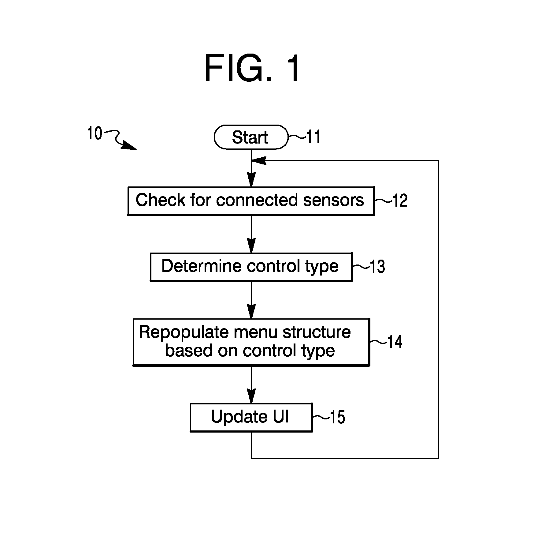
FIG. 1 is a flow diagram for the subject economizer controller plug and play system recognition with automatic user interface population;
FIGS. 2a, 2b, 3a, 3b, 4a, 4b, 5a and 5b are diagrams of several examples of configurations and menus based on mode; and
FIG. 6 is a schematic diagram of a representative economizer controller system which may be an illustrative system associated with examples of the present disclosure.
DESCRIPTION
There may be numerous economizer system configurations and control types. A system configuration may include many combinations of mixed air temperature sensing, outdoor air temperature sensing, return air temperature sensing, outdoor air humidity sensing, return air humidity sensing, discharge air temperature sensing, discharge air humidity sensing, and/or other sensing. The system control types may consist of single ended drybulb control, differential drybulb control, single ended enthalpy control, differential enthalpy control, hybrid control strategies, and/or other controls. Each system configuration and control type may have specific user interface (UI) population and setup requirements.
The present approach may solve the issue by implementing an automatic system configuration determination routine in controller firmware. Periodically, the controller may search for attached sensors and determine the appropriate control type and populate the user interface menu structure accordingly. The controller may have a graphical user interface.
An economizer/DCV (demand controlled ventilation) controller may have the present system recognition and automatic user interface population routine implemented in firmware.
FIG. 1 is a flow diagram 10 for the subject economizer controller plug and play system recognition with automatic user interface population. From a start 11, the system may check for connected sensors at symbol 12. The control type of the sensors may be determined at symbol 13. The menu structure may be repopulated based on control type at symbol 14. Then the user interface may be updated at symbol 15. The approach may be redone to check again for connected sensors by returning to symbol 12.
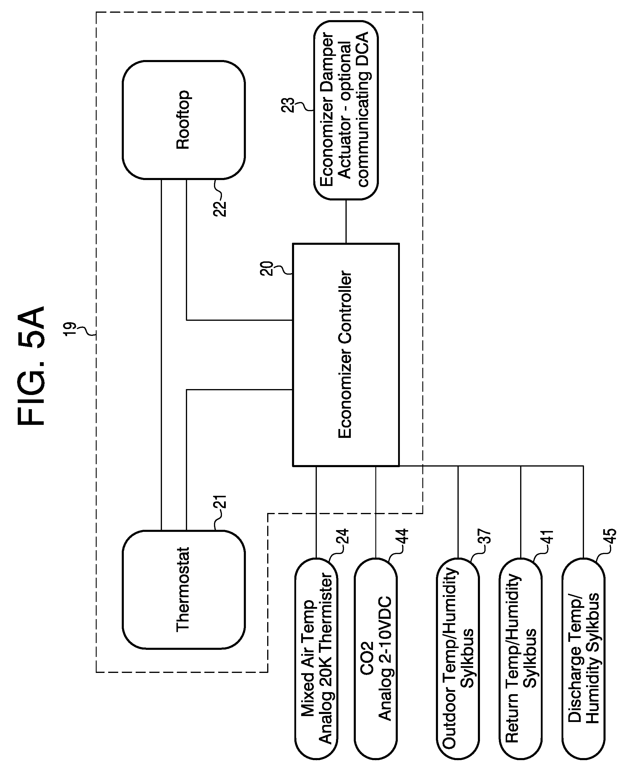
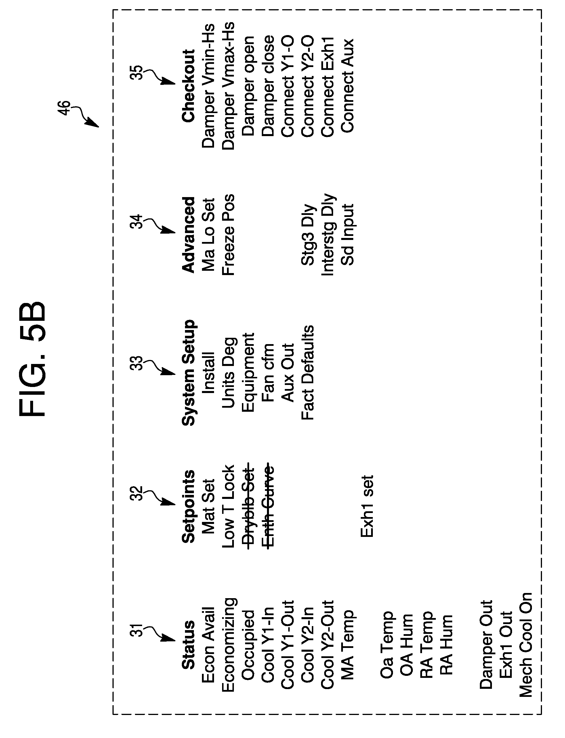
FIGS. 2a-5b are diagrams of several examples of configurations and menus based on mode. In FIG. 2a, the setup may begin with an economizer controller 20 having a thermostat 21 connected to the economizer 20 and a rooftop unit 22. Thermostat 21 and rooftop 22 may be connected to economizer controller 20. Also connected to controller 20 may be an economizer damper actuator 23. There may be an optional communicating demand control actuator (DCA). Components 20-23 may make up a combination 19 that is present in FIGS. 2a, 3a, 4a and 5a. FIGS. 2b, 3b, 4b and 5b reveal a menu structure with headings of status 31, setpoints 32, system setup 33, advanced 34 and checkout 35.
FIG. 2a is a diagram for a setup for a single dry bulb. A mixed air temperature (MAT) analog 20K ohm thermister 24 and an outdoor air temperature (OAT) analog 20K ohm thermister 25 may be connected to controller 20 of combination 19. FIG. 2b is a table 27 revealing a menu associated with the single dry bulb of a check for connected sensors, determination of control type, repopulation of menu structure based on control type, and update of user interface of the process 10 of FIG. 1. The headings may incorporate Status 31, Setpoint 32, System Setup 33, Advanced 34 and Checkout 35. Status 31 may have a listing of "Econ Avail," "Economizing", "Occupied", "Cool Y1-In", "Cool Y1-Out", "Cool Y2-In", "Cool Y2-Out', "MA Temp", "OA Temp", "Damper Out", "Exh1 Out" and "Mech Cool On". Setpoints 32 may have a listing of "Mat Set", "Low T Lock" "Dryblb Set", "Enth Curve", "Min Pos" and "Exh1 Set". System Setup 33 may have a listing of "Install", "Units Deg", "Equipment", "Fan cfm", "Aux Out" and "Fact Defaults". Advanced 34 may have a listing of "Ma Lo Set", "Freeze Pas", "Sta3 Dly", "Interstg Dly" and "Sd Input". Checkout 35 may have a listing of "Damper Vmin-Hs", "Damper Vmax-Hs", "Damper open", "Damper close", "Connect Y1-O", "Connect Y2-O", "Connect Exh1" and "Connect Aux".
FIG. 3a is a diagram for a setup for single enthalpy. The mixed air temperature analog 20K ohm thermister 24 and an outdoor temp/humidity sylkbus (Sylk.TM. bus) 37 may be connected to controller 20 of combination 19. FIG. 3b is a table 38 revealing a menu associated with the single enthalpy of a check for connected sensors, determination of control type, repopulation of menu structure based on control type, and update of the user interface of process 10. The headings of table 38 in FIG. 3b, as in FIG. 2b and FIGS. 4b and 5b, may incorporate Status 31, Setpoints 32, System Setup 33, Advanced 34 and Checkout 35. The headings Setpoints 32, System Setup 33, Advanced 34 and Checkout 35 of table 38 of FIG. 3b may have the same listings as the corresponding headings 32-35 of table 28 in FIG. 2b. Status 31 of FIG. 3b may have an additional item "OA Hum" after "OA Temp". Sylk.TM. bus may be a 2-wire, non-polarity sensitive, communications and power bus. Sylk.TM. is a trademark of Honeywell International Inc. of Morristown, N.J.
FIG. 4a is a diagram for a setup for differential enthalpy without DCV. The mixed air temperature analog 20K ohm thermister 24, the outdoor temp/humidity Sylkbus 37 and a return temp/humidity Sylkbus 41 may be connected to controller 20 of combination 19. FIG. 4b is a table 42 revealing a menu associated with the differential enthalpy without DCV of a check for connected sensors, determination of control type, repopulation of menu structure based on control type, and update of the user interface of process 10. The headings in FIG. 4b of table 42 may be the same as the headings in table 27. The listings of the headings in table 42 may differ from the listings in table 27 of FIG. 2b in that the "OA Hum', "RA Temp' and "RA Hum" may be present after "OA Temp" in the listing of Status 31. "Dryblb Set" and "Enth Curve" may be absent after "Low T Lock" in Setpoints 32 when compared with Setpoints 32 of table 27 in FIG. 2b. The remaining headings of table 42 may have the same listings as the corresponding headings of table 27.
FIG. 5a is a diagram for a setup for differential enthalpy with DCV. The mixed air temperature analog 20K ohm thermister 24, the outdoor temp/humidity Sylkbus 37, the return temp/humidity Sylkbus 41, a CO2 analog 2-10 VDC 44 and a discharge temp/humidity Sylkbus 45 may be connected to controller 20 of combination 19. FIG. 5b is a table 46 revealing a menu associated with the differential enthalpy with DCV of a check for connected sensors, determination of control type, repopulation of menu structure based on control type and update of the user interface of process 10. The headings of table 46 in FIG. 5b may be the same as the headings in table 27. The listings in table 46 may differ from the listings in table 27 of FIG. 2b in that "DA Temp" may be added after "MA Temp", "OA Hum", "RA Temp", "RA Hum", "in CO2" and "DCV Status" may be added after "OA Temp", in the listing of Status 31. "Dryblb Set", "Enth Curve" and "Min Pos" may be absent after "Low T Lock" in Setpoints 32 when compared with Setpoints 32 of table 27 in FIG. 2b. "DCV Set", "VentMax" and "VentMin" may be added to the listing of heading Setpoints 32 of table 46 when compared to table 27 in FIG. 2b. "CO2 Zero" may be added to the listing of the Advanced 34 heading. The Checkout 35 heading in table 46 may have the same listing as the Checkout 35 heading of table 27 in FIG. 2b.
FIG. 6 is a schematic diagram of a representative economizer controller system 50 which may be an illustrative system associated with the present approach. A thermostat 51 may be connected to an economizer logic module 52. A demand control ventilation sensor 53 may be connected to module 52. Return air 54 may come in through a recirculation damper 55 into a mixing air chamber 56 where air 54 may be mixed with outdoor air 57 coming through an intake damper 58. Mixed air may be discharge air 59 which is drawn by an indoor fan 61 through a direct expansion coil 62 and provided to a space being conditioned via a supply duct 68. Dampers 55 and 58 may be controlled by an actuator 63 which is connected to module 52. Damper 58 may close as damper 55 opens and vice versa. A portion of return air 54 may taken from return air duct 64 and drawn through a damper 65 by an exhaust fan 66 through an exhaust duct 76 to outside the system as exhaust air 67. Exhaust fan 66 may be connected to module 52. The position of damper 65 may be determined at least in part by module 52. The proportions of outdoor air 57 and recirculated air 54 taken into supply duct 68, as well as the amount of air 67 from return air duct 64, may be controlled by intake damper 58, recirculation damper 55 and exhaust damper 65. An enthalpy sensor 71 situated in an intake or outdoor air duct 73 may be connected to module 52. For differential enthalpy, a second enthalpy sensor 72, along with enthalpy sensor 71, may be connected to module 52.
A mixed air sensor 74 may be situated in chamber or duct 56, or a discharge air sensor 75 may situated in chamber or duct 68, but not necessarily both. One or the other of or both sensors 74 and 75 may be connected to logic module 52. There may be situations where there would be both a mixed air sensor in the mixed air chamber and a separate discharge air sensor in the discharge chamber or duct. There may also be situations where there is not a discharge air sensor but that a mixed air sensor is mounted in the discharge chamber or duct.
Economizer controller systems may save energy in buildings by using cool outside air as a means of cooling the indoor space. When the enthalpy of the outside air is less than the enthalpy of the recirculated air, conditioning the outside air may be more energy efficient than conditioning recirculated air. When the outside air is both sufficiently cool and sufficiently dry (depending on the climate), the amount of enthalpy in the air is acceptable to the control, no additional conditioning of it is necessarily needed. This portion of the economizer control scheme may be referred to as free cooling.
Economizer systems may reduce HVAC energy costs in cold and temperate climates while also potentially improving indoor air quality, but they might often not be appropriate in hot and humid climates. With the proper controls, economizer systems may be used in climates which experience various weather systems.
When the outside air's dry-bulb and wet-bulb temperatures are low enough, economizer systems may use water cooled by a wet cooling tower to cool buildings without operating a chiller. Often a plate-and-frame heat exchanger may be inserted between, for example, the cooling tower and chilled water loops.
To recap, an economizer controller system recognition approach may incorporate checking for connected sensors to an economizer controller of an economizer controller system, determining a control type of the connected sensors, repopulating a menu structure based on the control type, updating a user interface of the economizer controller system, and repeating the approach as desired or needed. The repopulating the menu structure may be automatic.
The economizer controller system may have a configuration, and the configuration may incorporate one or more combinations of sensing. The one or more combinations of sensing may incorporate mixed air temperature sensing, outdoor air temperature sensing, return air sensing, outdoor air humidity sensing, return air humidity sensing, discharge air temperature sensing, discharge air humidity sensing, and/or other applicable sensing.
The economizer controller system may incorporate one or more control types. The one or more control types may incorporate single ended drybulb control, differential drybulb control, single ended enthalpy control, differential enthalpy control, and/or other applicable control.
The economizer controller system may have a configuration and a control type. The configuration and control type may incorporate a specific user interface population and setup requirements. The economizer controller system may have an automatic system configuration determination routine in firmware of an economizer controller of the system.
The economizer controller system may periodically perform the checking for connected sensors, determining the control type of the connected sensors, and repopulating the user interface menu structure based on the control type. A control type of a sensor may incorporate status of the system, setpoints, system setup, advanced settings, checkout of dampers and ducts, and/or other applicable items.
The economizer controller system may incorporate an economizer controller, a rooftop economizer unit connected to the economizer controller, and a thermostat connected to the economizer controller and to the rooftop economizer unit. The economizer controller system may further incorporate an economizer damper actuator connected to the economizer controller.
This system may even further incorporate an outdoor air temperature sensor, a mixed air temperature sensor, an outdoor humidity sensor, a discharge air temperature sensor, a return air temperature sensor, a discharge air humidity sensor, a return air humidity sensor and/or a CO2 sensor connected to the economizer controller. One or more other applicable sensors may be connected to the economizer controller. The system may also have a communicating demand control actuator connected to the economizer controller.
A system having a recognition system with a user interface populating, may incorporate an economizer controller. The system may have a user interface connected to the economizer controller, a sensor checker for detecting sensors connected to the economizer controller, a type indicator for indicating a control type of the sensors, a mechanism for populating and/or repopulating a menu structure of the user interface, and/or other applicable mechanisms as appropriate. The repopulating the menu structure may be automatic. The sensor checker, type indicator and/or the mechanism for populating (and/or repopulating) may enable a plug and play aspect of the economizer controller.
The system may further incorporate a thermostat connected to the economizer controller, and an economizer rooftop unit connected to the mechanism for populating and/or repopulating and the thermostat.
An approach for updating a user interface of an economizer system, may incorporate providing an economizer controller having a user interface, providing a menu structure for the user interface, detecting sensors connected to the economizer controller, identifying a control type of the sensors connected to the economizer controller, and populating and/or repopulating the menu structure based on control type. The populating and/or repopulating the menu structure may be automatic. The economizer controller may have plug and play recognition.
U.S. Pat. Nos. 6,161,764, 4,570,448, and 7,434,413 may be relevant. U.S. Pat. No. 6,161,764, issued Dec. 19, 2000, is hereby incorporated by reference. U.S. Pat. No. 4,570,448, issued Feb. 18, 1986, is hereby incorporated by reference. U.S. Pat. No. 7,434,413, issued Oct. 14, 2008, is hereby incorporated by reference.
In the present specification, some of the matter may be of a hypothetical or prophetic nature although stated in another manner or tense.
Although the present system has been described with respect to at least one illustrative example, many variations and modifications will become apparent to those skilled in the art upon reading the specification. It is therefore the intention that the appended claims be interpreted as broadly as possible in view of the prior art to include all such variations and modifications.
* * * * *
References
-
content.honeywell.com/building/components/pr/econstudy.asp
-
automatedbuildings.com/releases/mar09/090312111454honeywell.htm
-
colemparmer.com/Assets/manual
-
nmschembio.org.uk/dm_uk/documents/Igcvam2003032_xsjgl.pdf
-
pexsupply.com/Honeywell-W7210A1001-Series-72-Economizer-TwoSPDT
-
ti.corn/lit/an/sboa111/sboa111.pdf
-
zipeconomizer.com/articlesresources
D00000
D00001
D00002
D00003
D00004
D00005
D00006
D00007
D00008
D00009
D00010
XML
uspto.report is an independent third-party trademark research tool that is not affiliated, endorsed, or sponsored by the United States Patent and Trademark Office (USPTO) or any other governmental organization. The information provided by uspto.report is based on publicly available data at the time of writing and is intended for informational purposes only.
While we strive to provide accurate and up-to-date information, we do not guarantee the accuracy, completeness, reliability, or suitability of the information displayed on this site. The use of this site is at your own risk. Any reliance you place on such information is therefore strictly at your own risk.
All official trademark data, including owner information, should be verified by visiting the official USPTO website at www.uspto.gov. This site is not intended to replace professional legal advice and should not be used as a substitute for consulting with a legal professional who is knowledgeable about trademark law.