Medical instrument with sensor for use in a system and method for electromagnetic navigation
Crowley , et al. October 1, 2
U.S. patent number 10,426,555 [Application Number 15/147,273] was granted by the patent office on 2019-10-01 for medical instrument with sensor for use in a system and method for electromagnetic navigation. This patent grant is currently assigned to COVIDIEN LP. The grantee listed for this patent is COVIDIEN LP. Invention is credited to David M. Costello, Thomas P. Crowley, Keith E. Jasperson, Lev A. Koyrakh, David J. Miel, Jon D. Schell, David J. Serdar, Joshua B. Stopek.


View All Diagrams
| United States Patent | 10,426,555 |
| Crowley , et al. | October 1, 2019 |
Medical instrument with sensor for use in a system and method for electromagnetic navigation
Abstract
A medical instrument includes a printed sensor, a surface, at least one non-conductive material, and at least one pair of contacts. The sensor has at least one coil formed on a conductive material. The surface is suitable for receiving the printed sensor and can be placed in an EM field. The at least one non-conductive material covers the at least one coil of the sensor. The medical instrument contains multiple conductive and nonconductive layers. The at least one pair of contacts are electrically connected to the at least one coil and connectable to the conductive layer, the conductive layer coupled to a measurement device, which senses an induced electrical signal based on a magnetic flux change of the EM field. The location of the medical instrument in a coordinate system of the EM filed is identified based on the induced electrical signal in the sensor.
| Inventors: | Crowley; Thomas P. (Lino Lakes, MN), Miel; David J. (Minneapolis, MN), Serdar; David J. (Shorewood, MN), Stopek; Joshua B. (Minneapolis, MN), Costello; David M. (Delano, MN), Koyrakh; Lev A. (Plymouth, MN), Jasperson; Keith E. (Andover, MN), Schell; Jon D. (Shoreview, MN) | ||||||||||
|---|---|---|---|---|---|---|---|---|---|---|---|
| Applicant: |
|
||||||||||
| Assignee: | COVIDIEN LP (Mansfield,
MA) |
||||||||||
| Family ID: | 57442074 | ||||||||||
| Appl. No.: | 15/147,273 | ||||||||||
| Filed: | May 5, 2016 |
Prior Publication Data
| Document Identifier | Publication Date | |
|---|---|---|
| US 20160354160 A1 | Dec 8, 2016 | |
Related U.S. Patent Documents
| Application Number | Filing Date | Patent Number | Issue Date | ||
|---|---|---|---|---|---|
| 62170383 | Jun 3, 2015 | ||||
| Current U.S. Class: | 1/1 |
| Current CPC Class: | A61B 10/04 (20130101); A61B 34/20 (20160201); A61B 5/062 (20130101); A61B 34/10 (20160201); A61B 10/06 (20130101); A61B 5/0071 (20130101); A61M 25/0105 (20130101); A61B 5/055 (20130101); A61B 10/0233 (20130101); A61B 1/2676 (20130101); A61B 2034/107 (20160201); A61M 2025/0166 (20130101); A61B 2017/00526 (20130101); A61B 2017/00929 (20130101); A61B 2034/2051 (20160201); A61B 2010/0216 (20130101); A61B 2017/00853 (20130101); A61B 2034/105 (20160201); A61B 2017/00699 (20130101); A61B 2017/00849 (20130101) |
| Current International Class: | A61B 5/00 (20060101); A61B 10/02 (20060101); A61B 10/06 (20060101); A61B 1/267 (20060101); A61B 34/10 (20160101); A61B 5/06 (20060101); A61B 10/04 (20060101); A61B 5/055 (20060101); A61B 34/20 (20160101); A61M 25/01 (20060101); A61B 17/00 (20060101) |
References Cited [Referenced By]
U.S. Patent Documents
| 1576781 | March 1926 | Phillips |
| 1735726 | November 1929 | Bornhardt |
| 2407845 | September 1946 | Nemeyer |
| 2650588 | September 1953 | Drew |
| 2697433 | December 1954 | Sehnder |
| 3016899 | January 1962 | Stenvall |
| 3017887 | January 1962 | Heyer |
| 3061936 | November 1962 | Dobbeleer |
| 3073310 | January 1963 | Mocarski |
| 3109588 | November 1963 | Polhemus et al. |
| 3294083 | December 1966 | Alderson |
| 3367326 | February 1968 | Frazier |
| 3439256 | April 1969 | Kahne et al. |
| 3577160 | May 1971 | White |
| 3614950 | October 1971 | Rabey |
| 3644825 | February 1972 | Davis, Jr. et al. |
| 3674014 | July 1972 | Tillander |
| 3702935 | November 1972 | Carey et al. |
| 3704707 | December 1972 | Halloran |
| 3821469 | June 1974 | Whetstone et al. |
| 3868565 | February 1975 | Kuipers |
| 3941127 | March 1976 | Froning |
| 3983474 | September 1976 | Kuipers |
| 4017858 | April 1977 | Kuipers |
| 4037592 | July 1977 | Kronner |
| 4052620 | October 1977 | Brunnett |
| 4054881 | October 1977 | Raab |
| 4117337 | September 1978 | Staats |
| 4173228 | November 1979 | Van Steenwyk et al. |
| 4182312 | January 1980 | Mushabac |
| 4202349 | May 1980 | Jones |
| 4228799 | October 1980 | Anichkov et al. |
| 4256112 | March 1981 | Kopf et al. |
| 4262306 | April 1981 | Renner |
| 4287809 | September 1981 | Egli et al. |
| 4298874 | November 1981 | Kuipers |
| 4314251 | February 1982 | Raab |
| 4317078 | February 1982 | Weed et al. |
| 4319136 | March 1982 | Jinkins |
| 4328548 | May 1982 | Crow et al. |
| 4328813 | May 1982 | Ray |
| 4339953 | July 1982 | Iwasaki |
| 4341220 | July 1982 | Perry |
| 4346384 | August 1982 | Raab |
| 4358856 | November 1982 | Stivender et al. |
| 4368536 | January 1983 | Pfeiler |
| 4394831 | July 1983 | Egli et al. |
| 4396885 | August 1983 | Constant |
| 4396945 | August 1983 | DiMatteo et al. |
| 4403321 | September 1983 | Kruger |
| 4418422 | November 1983 | Richter et al. |
| 4419012 | December 1983 | Stephenson et al. |
| 4422041 | December 1983 | Lienau |
| 4431005 | February 1984 | McCormick |
| 4447224 | May 1984 | DeCant, Jr. et al. |
| 4485815 | December 1984 | Amplatz et al. |
| 4506676 | March 1985 | Duska |
| 4543959 | October 1985 | Sepponen |
| 4548208 | October 1985 | Niemi |
| 4571834 | February 1986 | Fraser et al. |
| 4572198 | February 1986 | Codrington |
| 4583538 | April 1986 | Onik et al. |
| 4584577 | April 1986 | Temple |
| 4586491 | May 1986 | Carpenter |
| 4607619 | August 1986 | Seike et al. |
| 4608977 | September 1986 | Brown |
| 4613866 | September 1986 | Blood |
| 4617925 | October 1986 | Laitinen |
| 4618978 | October 1986 | Cosman |
| 4621628 | November 1986 | Brudermann |
| 4625718 | December 1986 | Olerud et al. |
| 4638798 | January 1987 | Shelden et al. |
| 4642786 | February 1987 | Hansen |
| 4645343 | February 1987 | Stockdale et al. |
| 4649504 | March 1987 | Krouglicof et al. |
| 4651732 | March 1987 | Frederick |
| 4653509 | March 1987 | Oloff et al. |
| 4659971 | April 1987 | Suzuki et al. |
| 4660970 | April 1987 | Ferrano |
| 4669172 | June 1987 | Petruzzi |
| 4673352 | June 1987 | Hansen |
| 4688037 | August 1987 | Krieg |
| 4701049 | October 1987 | Beckman et al. |
| 4705395 | November 1987 | Hageniers |
| 4705401 | November 1987 | Addleman et al. |
| 4706665 | November 1987 | Gouda |
| 4709156 | November 1987 | Murphy et al. |
| 4710708 | December 1987 | Rorden et al. |
| 4719419 | January 1988 | Dawley |
| 4722056 | January 1988 | Roberts et al. |
| 4722336 | February 1988 | Kim et al. |
| 4723544 | February 1988 | Moore et al. |
| 4727565 | February 1988 | Ericson |
| RE32619 | March 1988 | Damadian |
| 4733969 | March 1988 | Case et al. |
| 4737032 | April 1988 | Addleman et al. |
| 4737794 | April 1988 | Jones |
| 4737921 | April 1988 | Goldwasser et al. |
| 4742356 | May 1988 | Kuipers |
| 4742815 | May 1988 | Ninan et al. |
| 4743770 | May 1988 | Lee |
| 4743771 | May 1988 | Sacks et al. |
| 4745290 | May 1988 | Frankel et al. |
| 4750487 | June 1988 | Zanetti |
| 4753528 | June 1988 | Hines et al. |
| 4761072 | August 1988 | Pryor |
| 4764016 | August 1988 | Johansson |
| 4771787 | September 1988 | Wurster et al. |
| 4779212 | October 1988 | Levy |
| 4782239 | November 1988 | Hirose et al. |
| 4788481 | November 1988 | Niwa |
| 4791934 | December 1988 | Brunnett |
| 4793355 | December 1988 | Crum et al. |
| 4794262 | December 1988 | Sato et al. |
| 4797907 | January 1989 | Anderton |
| 4803976 | February 1989 | Frigg et al. |
| 4804261 | February 1989 | Kirschen |
| 4805615 | February 1989 | Carol |
| 4809679 | March 1989 | Shimonaka et al. |
| 4809694 | March 1989 | Ferrara |
| 4821200 | April 1989 | Oberg |
| 4821206 | April 1989 | Arora |
| 4821731 | April 1989 | Martinelli et al. |
| 4822163 | April 1989 | Schmidt |
| 4825091 | April 1989 | Breyer et al. |
| 4829373 | May 1989 | Leberl et al. |
| 4836778 | June 1989 | Baumrind et al. |
| 4838265 | June 1989 | Cosman et al. |
| 4841967 | June 1989 | Chang et al. |
| 4845771 | July 1989 | Wislocki et al. |
| 4849692 | July 1989 | Blood |
| 4860331 | August 1989 | Williams et al. |
| 4862893 | September 1989 | Martinelli |
| 4869247 | September 1989 | Howard, III et al. |
| 4875165 | October 1989 | Fencil et al. |
| 4875478 | October 1989 | Chen |
| 4884566 | December 1989 | Mountz et al. |
| 4889526 | December 1989 | Rauscher et al. |
| 4896673 | January 1990 | Rose et al. |
| 4905698 | March 1990 | Strohl, Jr. et al. |
| 4923459 | May 1990 | Nambu |
| 4931056 | June 1990 | Ghajar et al. |
| 4945305 | July 1990 | Blood |
| 4945914 | August 1990 | Allen |
| 4951653 | August 1990 | Fry et al. |
| 4951677 | August 1990 | Crowley et al. |
| 4955891 | September 1990 | Carol |
| 4961422 | October 1990 | Marchosky et al. |
| 4977655 | December 1990 | Martinelli |
| 4989608 | February 1991 | Ratner |
| 4991579 | February 1991 | Allen |
| 4994069 | February 1991 | Ritchart et al. |
| 5002058 | March 1991 | Martinelli |
| 5005592 | April 1991 | Cartmell |
| 5013317 | May 1991 | Cole et al. |
| 5016639 | May 1991 | Allen |
| 5017139 | May 1991 | Mushabac |
| 5027818 | July 1991 | Bova et al. |
| 5030196 | July 1991 | Inoue |
| 5030222 | July 1991 | Calandruccio et al. |
| 5031203 | July 1991 | Trecha |
| 5042486 | August 1991 | Pfeiler et al. |
| 5047036 | September 1991 | Koutrouvelis |
| 5050608 | September 1991 | Watanabe et al. |
| 5054492 | October 1991 | Scribner et al. |
| 5057095 | October 1991 | Fabian |
| 5059789 | October 1991 | Salcudean |
| 5078140 | January 1992 | Kwoh |
| 5079699 | January 1992 | Tuy et al. |
| 5086401 | February 1992 | Glassman et al. |
| 5094241 | March 1992 | Allen |
| 5097839 | March 1992 | Allen |
| 5098426 | March 1992 | Sklar et al. |
| 5099845 | March 1992 | Besz et al. |
| 5099846 | March 1992 | Hardy |
| 5104393 | April 1992 | Isner et al. |
| 5105829 | April 1992 | Fabian et al. |
| 5107839 | April 1992 | Houdek et al. |
| 5107843 | April 1992 | Aamio et al. |
| 5107862 | April 1992 | Fabian et al. |
| 5109194 | April 1992 | Cantaloube |
| 5119817 | June 1992 | Allen |
| 5142930 | September 1992 | Allen et al. |
| 5143076 | September 1992 | Hardy et al. |
| 5152288 | October 1992 | Hoenig et al. |
| 5160337 | November 1992 | Cosman |
| 5161536 | November 1992 | Vilkomerson et al. |
| 5178164 | January 1993 | Allen |
| 5178621 | January 1993 | Cook et al. |
| 5186174 | February 1993 | Schlondorff et al. |
| 5187475 | February 1993 | Wagener et al. |
| 5188126 | February 1993 | Fabian et al. |
| 5190059 | March 1993 | Fabian et al. |
| 5193106 | March 1993 | DeSena |
| 5197476 | March 1993 | Nowacki et al. |
| 5197965 | March 1993 | Cherry et al. |
| 5198768 | March 1993 | Keren |
| 5198877 | March 1993 | Schulz |
| 5207688 | May 1993 | Carol |
| 5211164 | May 1993 | Allen |
| 5211165 | May 1993 | Dumoulin et al. |
| 5211176 | May 1993 | Ishiguro et al. |
| 5212720 | May 1993 | Landi et al. |
| 5214615 | May 1993 | Bauer |
| 5219351 | June 1993 | Teubner et al. |
| 5222499 | June 1993 | Allen et al. |
| 5224049 | June 1993 | Mushabac |
| 5228442 | July 1993 | Imran |
| 5230338 | July 1993 | Allen et al. |
| 5230622 | July 1993 | Brossoit |
| 5230623 | July 1993 | Guthrie et al. |
| 5233990 | August 1993 | Bamea |
| 5237996 | August 1993 | Waldman et al. |
| 5249581 | October 1993 | Horbal et al. |
| 5251127 | October 1993 | Raab |
| 5251635 | October 1993 | Dumoulin et al. |
| 5253647 | October 1993 | Takahashi et al. |
| 5255680 | October 1993 | Darrow et al. |
| 5257636 | November 1993 | White |
| 5257998 | November 1993 | Ota et al. |
| 5261404 | November 1993 | Mick et al. |
| 5265610 | November 1993 | Darrow et al. |
| 5265611 | November 1993 | Hoenig et al. |
| 5269759 | December 1993 | Hernandez et al. |
| 5271400 | December 1993 | Dumoulin et al. |
| 5273025 | December 1993 | Sakiyama et al. |
| 5274551 | December 1993 | Corby, Jr. |
| 5279309 | January 1994 | Taylor et al. |
| 5285787 | February 1994 | Machida |
| 5291199 | March 1994 | Overman et al. |
| 5291889 | March 1994 | Kenet et al. |
| 5295483 | March 1994 | Nowacki et al. |
| 5297549 | March 1994 | Beatty et al. |
| 5299253 | March 1994 | Wessels |
| 5299254 | March 1994 | Dancer et al. |
| 5299288 | March 1994 | Glassman et al. |
| 5300080 | April 1994 | Clayman et al. |
| 5301061 | April 1994 | Nakada et al. |
| 5305091 | April 1994 | Gelbart et al. |
| 5305203 | April 1994 | Raab |
| 5306271 | April 1994 | Zinreich et al. |
| 5307072 | April 1994 | Jones, Jr. |
| 5309913 | May 1994 | Kormos et al. |
| 5315630 | May 1994 | Sturm et al. |
| 5316024 | May 1994 | Hirschi et al. |
| 5318025 | June 1994 | Dumoulin et al. |
| 5320111 | June 1994 | Livingston |
| 5325728 | July 1994 | Zimmerman et al. |
| 5325873 | July 1994 | Hirschi et al. |
| 5329944 | July 1994 | Fabian et al. |
| 5330485 | July 1994 | Clayman et al. |
| 5333168 | July 1994 | Fernandes et al. |
| 5353795 | October 1994 | Souza et al. |
| 5353800 | October 1994 | Pohndorf et al. |
| 5353807 | October 1994 | DeMarco |
| 5359417 | October 1994 | Muller et al. |
| 5368030 | November 1994 | Zinreich et al. |
| 5371778 | December 1994 | Yanof et al. |
| 5375596 | December 1994 | Twiss et al. |
| 5377678 | January 1995 | Dumoulin et al. |
| 5380302 | January 1995 | Orth |
| 5383454 | January 1995 | Bucholz |
| 5383852 | January 1995 | Stevens-Wright |
| 5385146 | January 1995 | Goldreyer |
| 5385148 | January 1995 | Lesh et al. |
| 5386828 | February 1995 | Owens et al. |
| 5389101 | February 1995 | Heilbrun et al. |
| 5391199 | February 1995 | Ben-Haim |
| 5394457 | February 1995 | Leibinger et al. |
| 5394875 | March 1995 | Lewis et al. |
| 5397329 | March 1995 | Allen |
| 5398684 | March 1995 | Hardy |
| 5399146 | March 1995 | Nowacki et al. |
| 5400384 | March 1995 | Fernandes et al. |
| 5402801 | April 1995 | Taylor |
| 5408409 | April 1995 | Glassman et al. |
| 5413573 | May 1995 | Koivukangas |
| 5417210 | May 1995 | Funda et al. |
| 5419325 | May 1995 | Dumoulin et al. |
| 5423334 | June 1995 | Jordan |
| 5425367 | June 1995 | Shapiro et al. |
| 5425382 | June 1995 | Golden et al. |
| 5426683 | June 1995 | O'Farrell, Jr. et al. |
| 5426687 | June 1995 | Goodall et al. |
| 5427097 | June 1995 | Depp |
| 5429132 | July 1995 | Guy et al. |
| 5433198 | July 1995 | Desai |
| RE35025 | August 1995 | Anderton |
| 5437277 | August 1995 | Dumoulin et al. |
| 5443066 | August 1995 | Dumoulin et al. |
| 5443489 | August 1995 | Ben-Haim |
| 5444756 | August 1995 | Pai et al. |
| 5445144 | August 1995 | Wodicka et al. |
| 5445150 | August 1995 | Dumoulin et al. |
| 5445166 | August 1995 | Taylor |
| 5446548 | August 1995 | Gerig et al. |
| 5447154 | September 1995 | Cinquin et al. |
| 5448610 | September 1995 | Yamamoto et al. |
| 5453686 | September 1995 | Anderson |
| 5456718 | October 1995 | Szymaitis |
| 5457641 | October 1995 | Zimmer et al. |
| 5458718 | October 1995 | Venkitachalam |
| 5464446 | November 1995 | Dreessen et al. |
| 5469847 | November 1995 | Zinreich et al. |
| 5474075 | December 1995 | Goldberg et al. |
| 5478341 | December 1995 | Cook et al. |
| 5478343 | December 1995 | Ritter |
| 5480422 | January 1996 | Ben-Haim |
| 5480439 | January 1996 | Bisek et al. |
| 5483961 | January 1996 | Kelly et al. |
| 5485849 | January 1996 | Panescu et al. |
| 5487391 | January 1996 | Panescu |
| 5487729 | January 1996 | Avellanet et al. |
| 5487757 | January 1996 | Truckai et al. |
| 5489256 | February 1996 | Adair |
| 5490196 | February 1996 | Rudich et al. |
| 5494034 | February 1996 | Schlondorff et al. |
| 5503416 | April 1996 | Aoki et al. |
| 5506102 | April 1996 | McDonnell |
| 5513637 | May 1996 | Twiss et al. |
| 5514146 | May 1996 | Lam et al. |
| 5515160 | May 1996 | Schulz et al. |
| 5517990 | May 1996 | Kalfas et al. |
| 5522815 | June 1996 | Durgin, Jr. et al. |
| 5531227 | July 1996 | Schneider |
| 5531520 | July 1996 | Grimson et al. |
| 5542938 | August 1996 | Avellanet et al. |
| 5543951 | August 1996 | Moehrmann |
| 5546940 | August 1996 | Panescu et al. |
| 5546949 | August 1996 | Frazin et al. |
| 5546951 | August 1996 | Ben-Haim |
| 5551429 | September 1996 | Fitzpatrick et al. |
| 5558091 | September 1996 | Acker et al. |
| 5566681 | October 1996 | Manwaring et al. |
| 5568384 | October 1996 | Robb et al. |
| 5568809 | October 1996 | Ben-haim |
| 5571083 | November 1996 | Lemelson |
| 5572999 | November 1996 | Funda et al. |
| 5573493 | November 1996 | Sauer et al. |
| 5573533 | November 1996 | Strul |
| 5575794 | November 1996 | Walus et al. |
| 5575798 | November 1996 | Koutrouvelis |
| 5577991 | November 1996 | Akui et al. |
| 5583909 | December 1996 | Hanover |
| 5588430 | December 1996 | Bova et al. |
| 5590215 | December 1996 | Allen |
| 5592939 | January 1997 | Martinelli |
| 5595193 | January 1997 | Walus et al. |
| 5596228 | January 1997 | Anderton et al. |
| 5600330 | February 1997 | Blood |
| 5603318 | February 1997 | Heilbrun et al. |
| 5611025 | March 1997 | Lorensen et al. |
| 5617462 | April 1997 | Spratt |
| 5617857 | April 1997 | Chader et al. |
| 5619261 | April 1997 | Anderton |
| 5622169 | April 1997 | Golden et al. |
| 5622170 | April 1997 | Schulz |
| 5627873 | May 1997 | Hanover et al. |
| 5628315 | May 1997 | Vilsmeier et al. |
| 5630431 | May 1997 | Taylor |
| 5636644 | June 1997 | Hart et al. |
| 5638819 | June 1997 | Manwaring et al. |
| 5640170 | June 1997 | Anderson |
| 5642395 | June 1997 | Anderton et al. |
| 5643175 | July 1997 | Adair |
| 5643268 | July 1997 | Vilsmeier et al. |
| 5645065 | July 1997 | Shapiro et al. |
| 5646524 | July 1997 | Gilboa |
| 5646525 | July 1997 | Gilboa |
| 5647361 | July 1997 | Damadian |
| 5662111 | September 1997 | Cosman |
| 5664001 | September 1997 | Tachibana et al. |
| 5674296 | October 1997 | Bryan et al. |
| 5676673 | October 1997 | Ferre et al. |
| 5681260 | October 1997 | Ueda et al. |
| 5682886 | November 1997 | Delp et al. |
| 5682890 | November 1997 | Kormos et al. |
| 5690108 | November 1997 | Chakeres |
| 5694945 | December 1997 | Ben-Haim |
| 5695500 | December 1997 | Taylor et al. |
| 5695501 | December 1997 | Carol et al. |
| 5696500 | December 1997 | Diem |
| 5697377 | December 1997 | Wittkampf |
| 5700236 | December 1997 | Sauer et al. |
| 5702406 | December 1997 | Vilsmeier et al. |
| 5711299 | January 1998 | Manwaring et al. |
| 5713853 | February 1998 | Clark et al. |
| 5713946 | February 1998 | Ben-Haim |
| 5715822 | February 1998 | Watkins et al. |
| 5715836 | February 1998 | Kliegis et al. |
| 5718241 | February 1998 | Ben-Haim et al. |
| 5727552 | March 1998 | Ryan |
| 5727553 | March 1998 | Saad |
| 5728047 | March 1998 | Edoga |
| 5729129 | March 1998 | Acker |
| 5730129 | March 1998 | Darrow et al. |
| 5730130 | March 1998 | Fitzpatrick et al. |
| 5732703 | March 1998 | Kalfas et al. |
| 5735278 | April 1998 | Hoult et al. |
| 5738096 | April 1998 | Ben-Haim |
| 5740802 | April 1998 | Natis et al. |
| 5741214 | April 1998 | Ouchi et al. |
| 5742394 | April 1998 | Hansen |
| 5744953 | April 1998 | Hansen |
| 5748767 | May 1998 | Raab |
| 5749362 | May 1998 | Funda et al. |
| 5749835 | May 1998 | Glantz |
| 5752513 | May 1998 | Acker et al. |
| 5755725 | May 1998 | Druais |
| RE35816 | June 1998 | Schulz |
| 5758667 | June 1998 | Slettenmark |
| 5762064 | June 1998 | Polvani |
| 5767669 | June 1998 | Hansen et al. |
| 5767699 | June 1998 | Bosnyak et al. |
| 5767960 | June 1998 | Orman |
| 5769789 | June 1998 | Wang et al. |
| 5769843 | June 1998 | Abela et al. |
| 5769861 | June 1998 | Vilsmeier |
| 5772594 | June 1998 | Barrick |
| 5775322 | July 1998 | Silverstein et al. |
| 5776064 | July 1998 | Kalfas et al. |
| 5782765 | July 1998 | Jonkman |
| 5787886 | August 1998 | Kelly et al. |
| 5792055 | August 1998 | McKinnon |
| 5795294 | August 1998 | Luber et al. |
| 5797849 | August 1998 | Vesely et al. |
| 5799055 | August 1998 | Peshkin et al. |
| 5799099 | August 1998 | Wang et al. |
| 5800352 | September 1998 | Ferre et al. |
| 5800535 | September 1998 | Howard, III |
| 5802719 | September 1998 | O'Farrell, Jr. et al. |
| 5803089 | September 1998 | Ferre et al. |
| 5807252 | September 1998 | Hassfeld et al. |
| 5810008 | September 1998 | Dekel et al. |
| 5810728 | September 1998 | Kuhn |
| 5810735 | September 1998 | Halperin et al. |
| 5820553 | October 1998 | Hughes |
| 5823192 | October 1998 | Kalend et al. |
| 5823958 | October 1998 | Truppe |
| 5828725 | October 1998 | Levinson |
| 5828770 | October 1998 | Leis et al. |
| 5829444 | November 1998 | Ferre et al. |
| 5831260 | November 1998 | Hansen |
| 5833608 | November 1998 | Acker |
| 5834759 | November 1998 | Glossop |
| 5836954 | November 1998 | Heilbrun et al. |
| 5840024 | November 1998 | Taniguchi et al. |
| 5840025 | November 1998 | Ben-Haim |
| 5843051 | December 1998 | Adams et al. |
| 5843076 | December 1998 | Webster, Jr. et al. |
| 5846183 | December 1998 | Chilcoat |
| 5848967 | December 1998 | Cosman |
| 5851183 | December 1998 | Bucholz |
| 5865726 | February 1999 | Katsurada et al. |
| 5865846 | February 1999 | Bryan et al. |
| 5868674 | February 1999 | Glowinski et al. |
| 5868675 | February 1999 | Henrion et al. |
| 5871445 | February 1999 | Bucholz |
| 5871455 | February 1999 | Ueno |
| 5871487 | February 1999 | Warner et al. |
| 5873822 | February 1999 | Ferre et al. |
| 5879499 | March 1999 | Corvi |
| 5882304 | March 1999 | Ehnholm et al. |
| 5884410 | March 1999 | Prinz |
| 5889834 | March 1999 | Vilsmeier et al. |
| 5891034 | April 1999 | Bucholz |
| 5891157 | April 1999 | Day et al. |
| 5893885 | April 1999 | Webster, Jr. |
| 5904691 | May 1999 | Barnett et al. |
| 5907395 | May 1999 | Schulz et al. |
| 5913820 | June 1999 | Bladen et al. |
| 5920395 | July 1999 | Schulz |
| 5921992 | July 1999 | Costales et al. |
| 5923727 | July 1999 | Navab |
| 5928248 | July 1999 | Acker |
| 5935160 | August 1999 | Auricchio et al. |
| 5938603 | August 1999 | Ponzi |
| 5938694 | August 1999 | Jaraczewski et al. |
| 5947925 | September 1999 | Ashiya et al. |
| 5947980 | September 1999 | Jensen et al. |
| 5947981 | September 1999 | Cosman |
| 5950629 | September 1999 | Taylor et al. |
| 5951475 | September 1999 | Gueziec et al. |
| 5951571 | September 1999 | Audette |
| 5954647 | September 1999 | Bova et al. |
| 5954796 | September 1999 | McCarty et al. |
| 5957844 | September 1999 | Dekel et al. |
| 5967980 | October 1999 | Ferre et al. |
| 5967982 | October 1999 | Barnett |
| 5968047 | October 1999 | Reed |
| 5971997 | October 1999 | Guthrie et al. |
| 5976156 | November 1999 | Taylor et al. |
| 5980535 | November 1999 | Bamett et al. |
| 5983126 | November 1999 | Wittkampf |
| 5987349 | November 1999 | Schulz |
| 5987960 | November 1999 | Messner et al. |
| 5999837 | December 1999 | Messner et al. |
| 5999840 | December 1999 | Grimson et al. |
| 6001130 | December 1999 | Bryan et al. |
| 6004269 | December 1999 | Crowley et al. |
| 6006126 | December 1999 | Cosman |
| 6006127 | December 1999 | Van Der Brug et al. |
| 6013087 | January 2000 | Adams et al. |
| 6014580 | January 2000 | Blume et al. |
| 6016439 | January 2000 | Acker |
| 6019725 | February 2000 | Vesely et al. |
| 6024695 | February 2000 | Taylor et al. |
| 6035229 | March 2000 | Silverstein et al. |
| 6050724 | April 2000 | Schmitz et al. |
| 6059718 | May 2000 | Taniguchi et al. |
| 6061588 | May 2000 | Thornton et al. |
| 6063022 | May 2000 | Ben-Haim |
| 6071288 | June 2000 | Carol et al. |
| 6073043 | June 2000 | Schneider |
| 6076008 | June 2000 | Bucholz |
| 6086529 | July 2000 | Arndt |
| 6096050 | August 2000 | Audette |
| 6104944 | August 2000 | Martinelli |
| 6112111 | August 2000 | Glantz |
| 6117070 | September 2000 | Akiba |
| 6118845 | September 2000 | Simon et al. |
| 6122538 | September 2000 | Sliwa, Jr. et al. |
| 6122541 | September 2000 | Cosman et al. |
| 6131396 | October 2000 | Duerr et al. |
| 6139183 | October 2000 | Graumann |
| 6147480 | November 2000 | Osadchy et al. |
| 6149592 | November 2000 | Yanof et al. |
| 6156067 | December 2000 | Bryan et al. |
| 6161032 | December 2000 | Acker |
| 6165181 | December 2000 | Heilbrun et al. |
| 6167296 | December 2000 | Shahidi |
| 6172499 | January 2001 | Ashe |
| 6175756 | January 2001 | Ferre et al. |
| 6178345 | January 2001 | Vilsmeier et al. |
| 6183444 | February 2001 | Glines et al. |
| 6188355 | February 2001 | Gilboa |
| 6192280 | February 2001 | Sommer et al. |
| 6194639 | February 2001 | Botella et al. |
| 6200262 | March 2001 | Ouchi |
| 6201387 | March 2001 | Govari |
| 6203493 | March 2001 | Ben-Haim |
| 6203497 | March 2001 | Dekel et al. |
| 6210362 | April 2001 | Ponzi |
| 6210378 | April 2001 | Ouchi |
| 6211666 | April 2001 | Acker |
| 6213995 | April 2001 | Steen et al. |
| 6216027 | April 2001 | Willis et al. |
| 6223067 | April 2001 | Vilsmeier et al. |
| 6226543 | May 2001 | Gilboa et al. |
| 6233476 | May 2001 | Strommer et al. |
| 6236875 | May 2001 | Bucholz et al. |
| 6246231 | June 2001 | Ashe |
| 6246784 | June 2001 | Summers et al. |
| 6253770 | July 2001 | Acker et al. |
| 6259942 | July 2001 | Westermann et al. |
| 6273896 | August 2001 | Franck et al. |
| 6285902 | September 2001 | Kienzle, III et al. |
| 6298262 | October 2001 | Franck et al. |
| 6314310 | November 2001 | Ben-Haim et al. |
| 6319250 | November 2001 | Falwell et al. |
| 6332089 | December 2001 | Acker et al. |
| 6335617 | January 2002 | Osadchy et al. |
| 6341231 | January 2002 | Ferre et al. |
| 6345112 | February 2002 | Summers et al. |
| 6351659 | February 2002 | Vilsmeier |
| 6366799 | April 2002 | Acker et al. |
| 6373240 | April 2002 | Govari |
| 6381485 | April 2002 | Hunter et al. |
| 6423009 | July 2002 | Downey et al. |
| 6424856 | July 2002 | Vilsmeier et al. |
| 6427314 | August 2002 | Acker |
| 6428547 | August 2002 | Vilsmeier et al. |
| 6434415 | August 2002 | Foley et al. |
| 6437567 | August 2002 | Schenck et al. |
| 6443894 | September 2002 | Sumanaweera et al. |
| 6445943 | September 2002 | Ferre et al. |
| 6447504 | September 2002 | Ben-Haim et al. |
| 6453190 | September 2002 | Acker et al. |
| 6468265 | October 2002 | Evans et al. |
| 6470207 | October 2002 | Simon et al. |
| 6474341 | November 2002 | Hunter et al. |
| 6478802 | November 2002 | Kienzle, III et al. |
| 6484049 | November 2002 | Seeley et al. |
| 6484118 | November 2002 | Govari |
| 6490475 | December 2002 | Seeley et al. |
| 6493573 | December 2002 | Martinelli et al. |
| 6498944 | December 2002 | Ben-Haim et al. |
| 6499488 | December 2002 | Hunter et al. |
| 6516046 | February 2003 | Frohlich et al. |
| 6527443 | March 2003 | Vilsmeier et al. |
| 6551325 | April 2003 | Neubauer et al. |
| 6580938 | June 2003 | Acker |
| 6584174 | June 2003 | Schubert et al. |
| 6585639 | July 2003 | Kotmel et al. |
| 6591129 | July 2003 | Ben-Haim et al. |
| 6593884 | July 2003 | Gilboa et al. |
| 6609022 | August 2003 | Vilsmeier et al. |
| 6611700 | August 2003 | Vilsmeier et al. |
| 6615155 | September 2003 | Gilboa |
| 6618612 | September 2003 | Acker et al. |
| 6640128 | October 2003 | Vilsmeier et al. |
| 6650927 | November 2003 | Keidar |
| 6666864 | December 2003 | Bencini et al. |
| 6676659 | January 2004 | Hutchins et al. |
| 6690963 | February 2004 | Ben-Haim et al. |
| 6694162 | February 2004 | Hartlep |
| 6701179 | March 2004 | Martinelli et al. |
| 6711429 | March 2004 | Gilboa et al. |
| 6712842 | March 2004 | Gifford, III et al. |
| 6751492 | June 2004 | Ben-Haim |
| 6770027 | August 2004 | Banik et al. |
| 6788967 | September 2004 | Ben-Haim et al. |
| 6796963 | September 2004 | Carpenter et al. |
| 6846286 | January 2005 | Suzuki et al. |
| 6947788 | September 2005 | Gilboa et al. |
| 6960161 | November 2005 | Amling et al. |
| 6995729 | February 2006 | Govari et al. |
| 7022066 | April 2006 | Yokoi et al. |
| 7101380 | September 2006 | Khachin et al. |
| 7182756 | February 2007 | Saeed et al. |
| 7197354 | March 2007 | Sobe |
| 7233820 | June 2007 | Gilboa |
| 7236567 | June 2007 | Sandkamp et al. |
| 7286868 | October 2007 | Govari |
| 7301332 | November 2007 | Govari et al. |
| 7321228 | January 2008 | Govari |
| 7324915 | January 2008 | Altmann et al. |
| 7343195 | March 2008 | Strommer et al. |
| 7353125 | April 2008 | Nieminen et al. |
| 7357795 | April 2008 | Kaji et al. |
| 7366562 | April 2008 | Dukesherer et al. |
| 7370656 | May 2008 | Gleich et al. |
| 7373271 | May 2008 | Schneider |
| 7386339 | June 2008 | Strommer et al. |
| 7397364 | July 2008 | Govari |
| 7399296 | July 2008 | Poole et al. |
| 7497029 | March 2009 | Plassky et al. |
| 7505809 | March 2009 | Strommer et al. |
| 7536218 | May 2009 | Govari et al. |
| RE40852 | July 2009 | Martinelli et al. |
| 7570987 | August 2009 | Raabe et al. |
| 7577474 | August 2009 | Vilsmeier |
| 7579837 | August 2009 | Fath et al. |
| 7587235 | September 2009 | Wist et al. |
| 7599535 | October 2009 | Kiraly et al. |
| 7599810 | October 2009 | Yamazaki |
| 7630753 | December 2009 | Simon et al. |
| 7634122 | December 2009 | Bertram et al. |
| 7636595 | December 2009 | Marquart et al. |
| 7641609 | January 2010 | Ohnishi et al. |
| 7648458 | January 2010 | Niwa et al. |
| 7652468 | January 2010 | Kruger et al. |
| 7657300 | February 2010 | Hunter et al. |
| 7659912 | February 2010 | Akimoto et al. |
| 7660623 | February 2010 | Hunter et al. |
| 7680528 | March 2010 | Pfister et al. |
| 7684849 | March 2010 | Wright et al. |
| 7686767 | March 2010 | Maschke |
| 7688064 | March 2010 | Shalgi et al. |
| 7696899 | April 2010 | Immerz et al. |
| 7697972 | April 2010 | Verard et al. |
| 7697973 | April 2010 | Strommer et al. |
| 7697974 | April 2010 | Jenkins et al. |
| 7720517 | May 2010 | Drysen |
| 7722565 | May 2010 | Wood et al. |
| 7725154 | May 2010 | Beck et al. |
| 7725164 | May 2010 | Suurmond et al. |
| 7727269 | June 2010 | Abraham-Fuchs et al. |
| 7729742 | June 2010 | Govari |
| 7744605 | June 2010 | Vilsmeier et al. |
| 7747307 | June 2010 | Wright et al. |
| 7751865 | July 2010 | Jascob et al. |
| 7998062 | August 2011 | Gilboa |
| 8190238 | May 2012 | Moll et al. |
| 8828201 | September 2014 | Simpson |
| 8932207 | January 2015 | Greenburg et al. |
| 2001/0007918 | July 2001 | Vilsmeier et al. |
| 2001/0007925 | July 2001 | Ritchart et al. |
| 2001/0031919 | October 2001 | Strommer et al. |
| 2001/0034530 | October 2001 | Malackowski et al. |
| 2001/0036245 | November 2001 | Kienzle et al. |
| 2002/0026097 | February 2002 | Akiba |
| 2002/0067408 | June 2002 | Adair et al. |
| 2002/0087100 | July 2002 | Onuki et al. |
| 2002/0095081 | July 2002 | Vilsmeier |
| 2002/0128565 | September 2002 | Rudy |
| 2002/0137014 | September 2002 | Anderson et al. |
| 2002/0162555 | November 2002 | West et al. |
| 2002/0165503 | November 2002 | Morris et al. |
| 2002/0173689 | November 2002 | Kaplan |
| 2002/0193686 | December 2002 | Gilboa |
| 2003/0018251 | January 2003 | Solomon |
| 2003/0028096 | February 2003 | Niwa et al. |
| 2003/0040657 | February 2003 | Yamaya et al. |
| 2003/0074011 | April 2003 | Gilboa et al. |
| 2003/0086599 | May 2003 | Armato et al. |
| 2003/0114742 | June 2003 | Lewkowicz et al. |
| 2003/0142753 | July 2003 | Gunday |
| 2003/0160721 | August 2003 | Gilboa et al. |
| 2003/0171653 | September 2003 | Yokoi et al. |
| 2003/0227547 | December 2003 | Iddan |
| 2004/0015049 | January 2004 | Zaar |
| 2004/0024309 | February 2004 | Ferre et al. |
| 2004/0086161 | May 2004 | Sivaramakrishna et al. |
| 2004/0097804 | May 2004 | Sobe |
| 2004/0138548 | July 2004 | Strommer et al. |
| 2004/0169509 | September 2004 | Czipott et al. |
| 2004/0249267 | December 2004 | Gilboa |
| 2004/0260201 | December 2004 | Mueller |
| 2005/0022993 | February 2005 | Wilson et al. |
| 2005/0033149 | February 2005 | Strommer et al. |
| 2005/0075680 | April 2005 | Lowry |
| 2005/0080342 | April 2005 | Gilreath et al. |
| 2005/0085715 | April 2005 | Dukesherer et al. |
| 2005/0107688 | May 2005 | Strommer |
| 2005/0119527 | June 2005 | Banik et al. |
| 2005/0197566 | September 2005 | Strommer et al. |
| 2005/0229934 | October 2005 | Willeford |
| 2006/0015126 | January 2006 | Sher |
| 2006/0058647 | March 2006 | Strommer et al. |
| 2006/0064006 | March 2006 | Strommer et al. |
| 2006/0069313 | March 2006 | Couvillon et al. |
| 2006/0149134 | July 2006 | Soper et al. |
| 2007/0015964 | January 2007 | Eversull et al. |
| 2007/0163597 | July 2007 | Mikkaichi et al. |
| 2007/0167714 | July 2007 | Kiraly et al. |
| 2007/0167738 | July 2007 | Timinger et al. |
| 2007/0167743 | July 2007 | Honda et al. |
| 2007/0167806 | July 2007 | Wood et al. |
| 2007/0197896 | August 2007 | Moll et al. |
| 2007/0225559 | September 2007 | Clerc et al. |
| 2007/0265639 | November 2007 | Danek et al. |
| 2007/0287901 | December 2007 | Strommer et al. |
| 2007/0293721 | December 2007 | Gilboa |
| 2008/0086051 | April 2008 | Voegele |
| 2008/0097187 | April 2008 | Gielen et al. |
| 2008/0118135 | May 2008 | Averbuch et al. |
| 2008/0125760 | May 2008 | Gilboa |
| 2008/0132757 | June 2008 | Tgavalekos |
| 2008/0132909 | June 2008 | Jascob et al. |
| 2008/0132911 | June 2008 | Sobe |
| 2008/0139886 | June 2008 | Tatsuyama |
| 2008/0139915 | June 2008 | Dolan et al. |
| 2008/0144909 | June 2008 | Wiemker et al. |
| 2008/0147000 | June 2008 | Seibel et al. |
| 2008/0154172 | June 2008 | Mauch |
| 2008/0157755 | July 2008 | Kruger et al. |
| 2008/0161682 | July 2008 | Kendrick et al. |
| 2008/0162074 | July 2008 | Schneider |
| 2008/0183071 | July 2008 | Strommer et al. |
| 2008/0188749 | August 2008 | Rasche et al. |
| 2009/0182224 | July 2009 | Shmarak et al. |
| 2009/0234223 | September 2009 | Onoda et al. |
| 2010/0016757 | January 2010 | Greenburg et al. |
| 2011/0207997 | August 2011 | Greenburg et al. |
| 2012/0150022 | June 2012 | Bar-Tal et al. |
| 2013/0066194 | March 2013 | Seter |
| 964149 | Mar 1975 | CA | |||
| 3042343 | Jun 1982 | DE | |||
| 3508730 | Sep 1986 | DE | |||
| 3520782 | Dec 1986 | DE | |||
| 3717871 | Dec 1988 | DE | |||
| 3831278 | Mar 1989 | DE | |||
| 3838011 | Jul 1989 | DE | |||
| 4213426 | Oct 1992 | DE | |||
| 4225112 | Dec 1993 | DE | |||
| 4233978 | Apr 1994 | DE | |||
| 19610984 | Sep 1997 | DE | |||
| 19715202 | Oct 1998 | DE | |||
| 19751761 | Oct 1998 | DE | |||
| 19832296 | Feb 1999 | DE | |||
| 19747427 | May 1999 | DE | |||
| 10085137 | Nov 2002 | DE | |||
| 0062941 | Oct 1982 | EP | |||
| 0119660 | Sep 1984 | EP | |||
| 0155857 | Sep 1985 | EP | |||
| 0319844 | Jun 1989 | EP | |||
| 0326768 | Aug 1989 | EP | |||
| 0350996 | Jan 1990 | EP | |||
| 0419729 | Apr 1991 | EP | |||
| 0427358 | May 1991 | EP | |||
| 0456103 | Nov 1991 | EP | |||
| 0581704 | Feb 1994 | EP | |||
| 0600610 | Jun 1994 | EP | |||
| 0651968 | May 1995 | EP | |||
| 0796633 | Sep 1997 | EP | |||
| 0857461 | Aug 1998 | EP | |||
| 0894473 | Feb 1999 | EP | |||
| 0908146 | Apr 1999 | EP | |||
| 0 922 966 | Jun 1999 | EP | |||
| 0930046 | Jul 1999 | EP | |||
| 1078644 | Feb 2001 | EP | |||
| 1255113 | Nov 2002 | EP | |||
| 2096523 | Sep 2009 | EP | |||
| 2755554 | Jul 2014 | EP | |||
| 2417970 | Sep 1979 | FR | |||
| 2618211 | Jan 1989 | FR | |||
| 2094590 | Sep 1982 | GB | |||
| 2164856 | Apr 1986 | GB | |||
| 63-240851 | Oct 1988 | JP | |||
| 03-267054 | Nov 1991 | JP | |||
| 06194639 | Jul 1994 | JP | |||
| 07-043619 | Feb 1995 | JP | |||
| 10-197807 | Jul 1998 | JP | |||
| 2000-075218 | Mar 2000 | JP | |||
| 88/09151 | Dec 1988 | WO | |||
| 89/05123 | Jun 1989 | WO | |||
| 90/05494 | May 1990 | WO | |||
| 91/03982 | Apr 1991 | WO | |||
| 91/04711 | Apr 1991 | WO | |||
| 91/07726 | May 1991 | WO | |||
| 92/03090 | Mar 1992 | WO | |||
| 92/06645 | Apr 1992 | WO | |||
| 94/04938 | Mar 1994 | WO | |||
| 94/23647 | Oct 1994 | WO | |||
| 94/24933 | Nov 1994 | WO | |||
| 95/07055 | Mar 1995 | WO | |||
| 9605768 | Feb 1996 | WO | |||
| 96/11624 | Apr 1996 | WO | |||
| 96/32059 | Oct 1996 | WO | |||
| 97/29682 | Aug 1997 | WO | |||
| 97/29684 | Aug 1997 | WO | |||
| 97/36192 | Oct 1997 | WO | |||
| 97/49453 | Dec 1997 | WO | |||
| 98/08554 | Mar 1998 | WO | |||
| 98/38908 | Sep 1998 | WO | |||
| 99/15097 | Apr 1999 | WO | |||
| 99/21498 | May 1999 | WO | |||
| 99/23956 | May 1999 | WO | |||
| 99/26549 | Jun 1999 | WO | |||
| 99/27839 | Jun 1999 | WO | |||
| 99/29253 | Jun 1999 | WO | |||
| 99/32033 | Jul 1999 | WO | |||
| 99/33406 | Jul 1999 | WO | |||
| 99/37208 | Jul 1999 | WO | |||
| 99/38449 | Aug 1999 | WO | |||
| 99/52094 | Oct 1999 | WO | |||
| 99/60939 | Dec 1999 | WO | |||
| 00/06701 | Feb 2000 | WO | |||
| 00/10456 | Mar 2000 | WO | |||
| 00/16684 | Mar 2000 | WO | |||
| 00/35531 | Jun 2000 | WO | |||
| 01/30437 | May 2001 | WO | |||
| 01/67035 | Sep 2001 | WO | |||
| 01/87136 | Nov 2001 | WO | |||
| 01/87398 | Nov 2001 | WO | |||
| 01/91842 | Dec 2001 | WO | |||
| 02/24054 | Mar 2002 | WO | |||
| 02/064011 | Aug 2002 | WO | |||
| 02/070047 | Sep 2002 | WO | |||
| 03/086498 | Oct 2003 | WO | |||
| 2004/023986 | Mar 2004 | WO | |||
| 2005025635 | Mar 2005 | WO | |||
| 2007033379 | Mar 2007 | WO | |||
| 2013/038354 | Mar 2013 | WO | |||
| 2013/056006 | Apr 2013 | WO | |||
| 2013/98715 | Jul 2013 | WO | |||
| 2014/061354 | Apr 2014 | WO | |||
| 2015116687 | Aug 2015 | WO | |||
Other References
|
McKenna, N.J. et al., "Nuclear Receptor Coregulators: Cellular and Molecular Biology," Endocrine Reviews 20(3): 321-344, Jun. 1, 1999, 24 pages. cited by applicant . Ding, X.F. et al., "Nuclear Receptor-Binding Sites of Coactivators Glucocorticoid Receptor Interacting Protein 1 (GRIP1) and Steroid Receptor Coactivator 1 (SRC-1): Multiple Motifs with Different Binding Specificities," Molecular Endocrinology12:302-313, Feb. 1, 1998 (9 pages). cited by applicant . Stenoien, D.L. et al., "Ligand-Mediated Assembly and Real-Time Cellular Dynamics of Estrogen Receptor .alpha.-Coactivator Complexes in Living Cells," Molecular and Cellular Biology, Jul. 2001, pp. 4404-4412, 9 pages. cited by applicant . International Search Report and Written Opinion from Appl. No. PCT/US2016/033063 dated Aug. 16, 2016. cited by applicant . Chinese Office Action dated Jan. 7, 2019 issued in corresponding CN Appln. No. 2016800320825. (Summary only). cited by applicant . Extended European Search Report issued in corresponding Appl. No. EP 16803978.2 dated Feb. 21, 2019 (8 pages). cited by applicant. |
Primary Examiner: Laneau; Ronald
Parent Case Text
CROSS REFERENCE TO RELATED APPLICATION
The present application claims the benefit of and priority to U.S. Provisional Application Ser. No. 62/170,383, filed on Jun. 3, 2015, the entire contents of which are incorporated herein by reference.
Claims
What is claimed is:
1. A medical instrument, comprising: a base non-conductive layer on a distal portion of the medical instrument; a sensor printed on the base non-conductive layer, the sensor including a first conductive coil, a second conductive coil, and a non-conductive layer disposed between the first conductive coil and the second conductive coil; a proximal conductive layer printed circumferentially around a proximal portion of the medical instrument; a proximal non-conductive layer printed on the proximal conductive layer; and at least one pair of contacts electrically connected to at least one of the first conductive coil or the second conductive coil of the sensor and coupled to the proximal conductive layer, the proximal conductive layer connectable to a measurement device configured to sense an induced electrical signal in the sensor based on a magnetic flux change of an electromagnetic field, wherein a location of the medical instrument in a coordinate system of the electromagnetic field is identified based on the induced electrical signal in the sensor.
2. The medical instrument according to claim 1, wherein each of the first conductive coil and the second conductive coil includes a conductive layer formed of a conductive material, the conductive layer of the first conductive coil having a different configuration from a configuration of the conductive layer of the second conductive coil.
3. The medical instrument according to claim 2, wherein the different configuration includes a pitch angle and a number of loops of the conductive material.
4. The medical instrument according to claim 1, wherein the proximal portion of the medical instrument includes a plurality of proximal conductive layers and proximal non-conductive layers printed on the proximal portion of the medical instrument.
5. The medical instrument according to claim 4, wherein each proximal conductive layer of the plurality of proximal conductive layers is coupled to at least one of the first conductive coil or the second conductive coil of the sensor.
6. The medical instrument according to claim 1, wherein at least one of the first conductive coil or the second conductive coil of the sensor is connected to the proximal conductive layer through vias.
7. The medical instrument according to claim 1, wherein at least one of the first conductive coil or the second conductive coil of the sensor forms a helical shape.
8. The medical instrument according to claim 7, wherein the helical shape is counter clockwise.
9. The medical instrument according to claim 7, wherein the helical shape is clockwise.
10. The medical instrument according to claim 1, wherein an outer surface of the medical instrument is made of ETFE, PTFE, polyimide, or non-conductive polymer.
11. The medical instrument according to claim 1, wherein at least one of the first conductive coil or the second conductive coil of the sensor includes copper, silver, gold, conductive alloys, or conductive polymer.
12. The medical instrument according to claim 1, wherein the medical instrument is an extended working channel, an imaging instrument, a biopsy forceps, a biopsy brush, a biopsy needle, or a microwave ablation probe.
13. A sensor, comprising: a first conductive coil positioned at a distal portion of a medical instrument; a non-conductive layer positioned on at least a portion of the first conductive coil at the distal portion of the medical instrument; and a second conductive coil positioned on at least a portion of the non-conductive layer at the distal portion of the medical instrument, wherein the first conductive coil is spaced apart from the second conductive coil along a direction orthogonal to a surface of the non-conductive layer facing the first conductive coil.
14. The sensor according to claim 13, wherein the first conductive coil overlaps the second conductive coil along the direction orthogonal to the surface of the non-conductive layer facing the first conductive coil.
15. The sensor according to claim 13, wherein the first conductive coil is positioned on a non-conductive base layer of the medical instrument.
16. A medical instrument, comprising: a sensor positioned at a distal portion of the medical instrument, the sensor comprising: a first conductive coil positioned at the distal portion of the medical instrument; a non-conductive layer positioned on at least a portion of the first conductive coil; and a second conductive coil positioned on at least a portion of the non-conductive layer; and a tracking device configured to sense an induced electrical signal in the sensor based on a variation of an electromagnetic field, wherein a location of the sensor in a coordinate system of the electromagnetic field is configured to be determined by the tracking device based on the induced electrical signal in the sensor.
17. The medical instrument according to claim 16, wherein the first conductive coil overlaps the second conductive coil along a direction orthogonal to a surface of the non-conductive layer facing the first conductive coil.
18. The medical instrument according to claim 16, wherein the first conductive coil is positioned on a non-conductive base layer of the medical instrument.
19. The medical instrument according to claim 16, wherein the first conductive coil includes copper, silver, gold, a conductive alloy, or a conductive polymer.
20. The medical instrument according to claim 16, wherein the medical instrument is an extended working channel, an imaging instrument, a biopsy forceps, a biopsy brush, a biopsy needle, or a microwave ablation probe.
Description
BACKGROUND
Technical Field
The present disclosure relates to a medical instrument including a sensor, and a system in which the location of the sensor can be detected and tracked. More particularly, the present disclosure relates to systems and methods that identify a location of a medical instrument having the sensor in an electromagnetic field.
Discussion of Related Art
Electromagnetic navigation (EMN) has helped expand the possibilities of treatment to internal organs and diagnosis of diseases. EMN relies on non-invasive imaging technologies, such as computed tomography (CT) scanning, magnetic resonance imaging (MRI), or fluoroscopic technologies. These images may be registered to a location of a patient within a generated magnetic field, and as a result the location of a sensor placed in that field can be identified with reference to the images. As a result, EMN in combination with these non-invasive imaging technologies is used to identify a location of a target and to help clinicians navigate inside of the patient's body to the target.
In one particular example of currently marketed systems in the area of locating the position of medical instruments in a patient's airway, a sensor is placed at the end of a probe referred to as a locatable guide and passed through an extended working channel (EWC) or catheter, and the combination is inserted into the working channel of a bronchoscope. The EWC and probe with sensor is then navigated to the target within the patient. Once the target is reached, the locatable guide (i.e., sensor and probe) can be removed and one or more instruments, including biopsy needles, biopsy brushes, ablation catheters, and the like can be passed through the working channel and EWC to obtain samples and/or treat the target. At this point, however, because the locatable guide with its sensor have been removed, the exact location of a distal end of the EWC, and by extension any instrument which might be passed there through is not precisely known.
Images generated by the non-invasive imaging technologies described above do not provide the resolution of live video imaging. To achieve live video, a clinician may utilize the features of an endoscope. However, an endoscope is limited by its size and as a result cannot be navigated to the pleura boundaries of the lungs and other very narrow passageways as is possible with tools typically utilized in EMN. An alternative is a visualization instrument that is inserted through the EWC and working channel of the endoscope, which can be sized to reach areas such as the pleura boundaries.
As with the locatable guide, however, once the visualization instrument is removed the location of the distal end of the EWC is unclear. One technique that is used is the placement of one or more markers into the tissue near the target and the use of fluoroscopy to confirm location of the EWC and the markers, and any subsequent instruments passed through the EWC. Due to the small diameter of the EWC, simultaneous insertion of more than one instrument may be impractical. Thus, repeated insertions and removals of instruments for visualization, diagnosis, and surgeries are necessitated. Such repeated insertions and removals lengthen diagnostic or surgical time and efforts, and increase costs on patients correspondingly. Thus, it is desirous to make a fewer insertion and/or removal of instruments to shorten times necessary for diagnosis and surgeries while at the same time increasing the certainty of the location of the EWC and instruments passed through the EWC, including imaging modalities.
SUMMARY
As used herein, the term "distal" refers to the portion that is being described which is further from a user, while the term "proximal" refers to the portion that is being described which is closer to a user. Further, to the extent consistent, any of the aspects and features detailed herein may be used in conjunction with any or all of the other aspects and features detailed herein.
Provided in accordance with the present disclosure is a medical instrument having a distal portion and a proximal portion, the medical instrument comprising a sensor printed on a distal portion of the medical instrument and having at least one coil formed of a conductive material, at least one non-conductive material covering the at least one coil of the at least one sensor, a conductive layer printed circumferentially around the proximal portion of the medical instrument, a nonconductive layer printed on top of the conductive layer, and at least one pair of contacts electrically connected to the at least one coil and coupled to the conductive layer, the conductive layer connectable to a measurement device configured to sense an induced electrical signal based on a magnetic flux change of the electromagnetic field, wherein a location of the medical instrument in a coordinate system of the electromagnetic field is identified based on the induced electrical signal in the sensor.
According to aspects of the disclosure, the medical instrument comprises a base non-conductive layer on the distal portion of the medical instrument on which the conductive material is printed. The sensor may include multiple layers of the conductive material and the non-conductive material printed or fabricated on the distal portion of the medical instrument. Each conductive layer may have a different configuration, including a different pitch angle and/or the number of loops of the conductive material.
According to further aspects of the disclosure, the proximal portion of the medical instrument includes a plurality of conductive layers and non-conductive layers printed on the proximal portion of the medical instrument. Each conductive layer is coupled to one of the conductive materials of the sensor. The conductive material may further be connected to the conductive layer through vias. The conductive material may further form a helical shape which may be formed in a counter-clockwise or clockwise direction. In embodiments, the outer surface of the medical instrument is made of ETFE, PTFE, polyimide, or non-conductive polymer. The conductive materials may be copper, silver, gold, conductive alloys, or a conductive polymer. The medical instrument may be an extended working channel, an imaging instrument, a biopsy forceps, a biopsy brush, a biopsy needle, or a microwave ablation probe.
BRIEF DESCRIPTION OF THE DRAWINGS
Objects and features of the presently disclosed systems and methods will become apparent to those of ordinary skill in the art when descriptions of various embodiments are read with reference to the accompanying drawings, of which:
FIG. 1 is a perspective view of a system for identifying a location of a medical instrument in accordance with an embodiment of the present disclosure;
FIG. 2A is a profile view of a catheter guide assembly and medical instrument in accordance with an embodiment of the present disclosure;
FIG. 2B is an enlarged view of the indicated area of detail of FIG. 2A;
FIG. 3A depicts a sensor as a coil wound and printed at the distal portion of a medical instrument in accordance with an embodiment of the present disclosure;
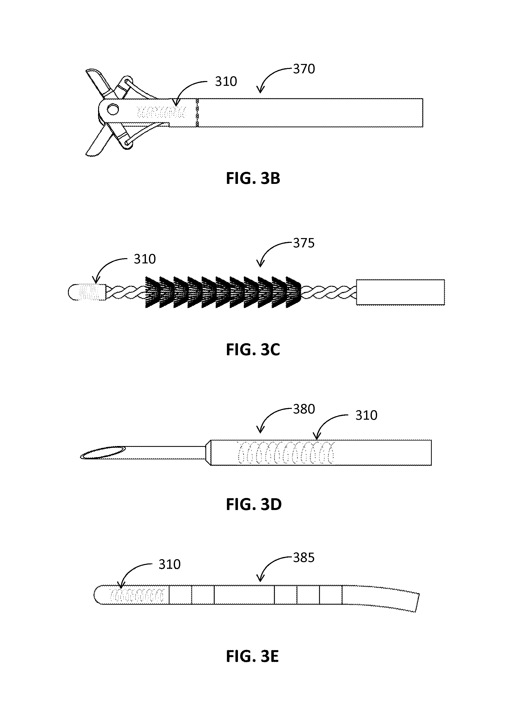
FIGS. 3B-3E are perspective views of a plurality of medical instruments in accordance with an embodiment of the present disclosure;
FIG. 4 is an expanded view of a distal portion of a medical instrument around which a circuit is printed in accordance with an embodiment of the present disclosure;
FIG. 5 is an illustrative design of a sensor including two-coils in a multi-layer circuit in accordance with an embodiment of the present disclosure;
FIG. 6A is an illustrative design of two sensors in a first layer of a multi-layer circuit in accordance with an embodiment of the present disclosure;
FIG. 6B is an illustrative design of a sensor in a second layer of a multi-layer circuit in accordance with an embodiment of the present disclosure;
FIG. 6C is an illustrative design of a proximal portion of a medical instrument around which a series of conductive and nonconductive layers are printed;
FIG. 7 is an illustration of a printer that prints a sensor on a surface of a medical instrument in accordance with an embodiment of the present disclosure; and
FIG. 8 is a flowchart of a method for printing a sensor on a medical instrument in accordance with an embodiment of the present disclosure.
DETAILED DESCRIPTION
The present disclosure is related to medical instruments, systems and methods for identifying a location of medical instruments in an electromagnetic field by using a sensor. The sensors may be printed directly on or separately fabricated and then affixed to the medical instruments, including imaging instruments. Since the sensor may be inserted inside of patient's body with medical instruments, the location of the medical instruments is identified in real-time. Further, the sensor may provide and trace an exact direction and location of the medical instrument with other imaging modalities. Due to the small size of the sensor, medical instruments may incorporate the sensor inside or outside of the medical instruments, to facilitate continuous navigation. Although the present disclosure will be described in terms of specific illustrative embodiments, it will be readily apparent to those skilled in this art that various modifications, rearrangements, and substitutions may be made without departing from the spirit of the present disclosure. The scope of the present disclosure is defined by the claims appended to this disclosure.
FIG. 1 illustrates one illustrative embodiment of a system and method for identifying a location of medical instruments in an electromagnetic field. In particular, an electromagnetic navigation (EMN) system 100, which is configured to utilize CT, MRI, or fluoroscopic images, is shown. One such EMN system may be the ELECTROMAGNETIC NAVIGATION BRONCHOSCOPY.RTM. system currently sold by Covidien LP. The EMN system 100 includes a catheter guide assembly 110, a bronchoscope 115, a computing device 120, a monitoring device 130, an EM board 140, a tracking device 160, and reference sensors 170. The bronchoscope 115 is operatively coupled to the computing device 120 and the monitoring device 130 via a wired connection (as shown in FIG. 1) or wireless connection (not shown).
FIG. 2A illustrates an embodiment of the catheter guide assembly 110 of FIG. 1. The catheter guide assembly 110 includes a control handle 210, which enables advancement and steering of the distal end 250 of the catheter guide assembly 110. The catheter guide assembly 110 includes a locatable guide catheter (LG) 220 inserted in the EWC 230 and an electromagnetic (EM) sensor 260, as shown in FIG. 2B. A locking mechanism 225 secures the EWC 230 and the LG 220 to one another. Catheter guide assemblies usable with the instant disclosure may be currently marketed and sold by Covidien LP under the name SUPERDIMENSION.RTM. Procedure Kits and EDGE.TM. Procedure Kits. For a more detailed description of the catheter guide assemblies, reference is made to commonly-owned U.S. patent application Ser. No. 13/836,203 filed on Mar. 15, 2013, by Ladtkow et al. and U.S. Pat. No. 7,233,820, the entire contents of which are incorporated in this disclosure by reference. As will be described in greater detail below, the EM sensor 260 on the distal portion of the LG 220 senses the electromagnetic field, and is used to identify the location of the LG 220 in the electromagnetic field. In embodiments, the EM sensor 260 can be directly integrated into the distal end of the EWC 230.
In use, the bronchoscope 115 is inserted into the mouth or through an incision of a patient 150 to capture images of the internal organ. In the EMN system 100, inserted into the bronchoscope 115 is a catheter guide assembly 110 for achieving an access to the internal organ of the patient 150. The catheter guide assembly 110 may include an extended working channel (EWC) 230 into which a locatable guide catheter (LG) 220 with the EM sensor 260 at the distal portion is inserted. The EWC 230, the LG 220, and the EM sensor 260 are used to navigate through the internal organ as described in greater detail below.
In an alternative embodiment, instead of a bronchoscope 115 inserted via a natural orifice the catheter guide assembly 110 is inserted into the patient 150 via an incision. The catheter guide assembly 110 including the EWC 230 may be inserted through the incision to navigate a luminal network other than the airways of a lung, such as the cardiac luminal network.
The computing device 120, such as, a laptop, desktop, tablet, or other similar computing device, includes a display 122, one or more processors 124, memory 126, a network card 128, and an input device 129. The EMN system 100 may also include multiple computing devices, wherein the separate computing devices are employed for planning, treatment, visualization, and other aspects of assisting clinicians in a manner suitable for medical operations. The display 122 may be touch-sensitive and/or voice-activated, enabling the display 122 to serve as both input and output devices. The display 122 may display two dimensional (2D) images or a three dimensional (3D) model of an internal organ, such as the lung, prostate, kidney, colon, liver, etc., to locate and identify a portion of the internal organ that displays symptoms of diseases.
The display 122 may further display options to select, add, and remove a target to be treated and settable items for the visualization of the internal organ. In an aspect, the display 122 may also display the location of the catheter guide assembly 110 in the electromagnetic field based on the 2D images or 3D model of the internal organ.
The one or more processors 124 execute computer-executable instructions. The processors 124 may perform image-processing functions so that the 3D model of the internal organ can be displayed on the display 122. In embodiments, the computing device 120 may further include a separate graphic accelerator (not shown) that performs only the image-processing functions so that the one or more processors 124 may be available for other programs. The memory 126 stores data and programs. For example, data may be image data for the 3D model or any other related data such as patients' medical records, prescriptions and/or history of the patient's diseases.
One type of programs stored in the memory 126 is a 3D model and pathway planning software module (planning software). An example of the 3D model generation and pathway planning software may be the ILOGIC.RTM. planning suite currently sold by Covidien LP. When image data of a patient, which is typically in digital imaging and communications in medicine (DICOM) format, from for example a CT image data set (or an image data set by other imaging modality) is imported into the planning software, a 3D model of the internal organ is generated. In an aspect, imaging may be done by CT imaging, magnetic resonance imaging (MRI), functional MRI, X-ray, and/or any other imaging modalities. To generate the 3D model, the planning software employs segmentation, surface rendering, and/or volume rendering. The planning software then allows for the 3D model to be sliced or manipulated into a number of different views including axial, coronal, and sagittal views that are commonly used to review the original image data. These different views allow the user to review all of the image data and identify potential targets in the images.
Once a target is identified, the software enters into a pathway planning module. The pathway planning module develops a pathway plan to achieve access to the targets and the pathway plan pin-points the location and identifies the coordinates of the target such that they can be arrived at using the EMN system 100, and particularly the catheter guide assembly 110 together with the EWC 230, the LG 220, and the EM sensor 260. The pathway planning module guides a clinician through a series of steps to develop a pathway plan for export and later use during navigation to the target in the patient 150. The term, clinician, may include doctor, surgeon, nurse, medical assistant, or any user of the pathway planning module involved in planning, performing, monitoring and/or supervising a medical procedure.
Details of these processes and the pathway planning module can be found in U.S. patent application Ser. No. 13/838,805 filed by Covidien LP on Jun. 21, 2013, and entitled "Pathway Planning System and Method," the entire contents of which are incorporated in this disclosure by reference. Such pathway planning modules permit clinicians to view individual slices of the CT image data set and to identify one or more targets. These targets may be, for example, lesions or the location of a nerve which affects the actions of tissue where the disease has rendered the internal organ's function compromised.
The memory 126 may store navigation and procedure software which interfaces with the EMN system 100 to provide guidance to the clinician and provide a representation of the planned pathway on the 3D model and 2D images derived from the 3D model. An example of such navigation software is the ILOGIC.RTM. navigation and procedure suite sold by Covidien LP. In practice, the location of the patient 150 in the EM field generated by the EM field generating device 145 must be registered to the 3D model and the 2D images derived from the 3D model. Such registration may be manual or automatic and is described in detail and commonly assigned U.S. Provisional Patent Application 62/020,240 entitled "System and method for navigating within the lung."
As shown in FIG. 1, the EM board 140 is configured to provide a flat surface for the patient to lie down and includes an EM field generating device 145. When the patient 150 lies down on the EM board 140, the EM field generating device 145 generates an EM field sufficient to surround a portion of the patient 150. The EM sensor 260 at the end of the LG 220 is used to determine the location of the distal end of the LG 220 and therewith the EWC 230 within the patient. In an aspect, a separate EM sensor may be located at the distal end of the EWC 230 and therewith the exact location of the EWC 230 in the EM field generated by the EM field generating device 145 can be identified within the patient 150.
In yet another aspect, the EM board 140 may be configured to be operatively coupled with the reference sensors 170 which are located on the chest of the patient 150. The reference sensors 170 move up following the chest while the patient 150 is inhaling and move down following the chest while the patient 150 is exhaling. The movement of the chest of the patient 150 in the EM field is captured by the reference sensors 170 and transmitted to the tracking device 160 so that the breathing pattern of the patient 150 may be recognized. The tracking device 160 also receives the output of the EM sensor 260, combines both outputs, and compensates the breathing pattern for the location of the EM sensor 260. In this way, the location identified by the EM sensor 260 may be compensated for such that the compensated location of the EM sensor 260 may be synchronized with the 3D model of the internal organ. As noted above, however, the use of an LG 230 with an EM sensor 260 at its distal end 250 can result in challenges surrounding instrument swaps, loss of location information, and a general prolongation of the time needed for a procedure. To alleviate these issues, FIG. 3A depicts an electromagnetic sensor 310 in the shape of a coil. The sensor 310 may be printed directly on the distal portion of a medical instrument 300. The printed electromagnetic sensor (PES) 310 may form a helical shape, as depicted or in another configuration as required by the application. The instrument 300 may be the EWC 230, a catheter, a biopsy instrument, an ablation instrument, a monopolar or bipolar electrosurgical instrument, an imaging instrument, a marking instrument, or a needle, in short any instrument capable of being inserted into the luminal network (e.g., the airways or vasculature of a patient). In one embodiment the instrument 300 is sized to pass through the EWC 230. Alternatively, the instrument 300 may be the EWC 230, as described in more detail below. Other exemplary instruments are shown in FIGS. 3B-3E, depicting biopsy forceps 370, a biopsy brush 375, a biopsy needle 380, and a microwave ablation probe 385, each having an EM sensor 310 applied by the methods of the present disclosure.
As will be described in greater detail below, the distal portion of the instrument 300 may be made of or covered by Ethylene tetrafluoroethylene (ETFE), Polytetrafluoroethylene (PTFE), polyimide, or another suitable material to form a non-conductive base for the sensor 310. If the distal portion of the instrument 300 is not covered or made of a non-conductive material, a non-conductive material must be applied to the distal portion first to form an insulating base for the sensor 310.
With respect to the sensor 310 depicted in FIG. 3A, the coil of sensor 310 is in the shape of a helix. The dimensions of the helix (i.e., the length L, the distance d between two adjacent loops, and a diameter D of the helix, as shown in FIG. 3A) may be chosen to create an optimum sensor 310. A pitch angle .alpha. may be used to define the helix and be calculated by:
.alpha..function..pi..times..times. ##EQU00001## The pitch angle .alpha. indicates the density of loops of the printed helix along the longitudinal axis of the instrument 300.
In embodiments, the sensor 310 may include multiple layers. Specifically, after a conductive material is applied to the instrument 300 to form a first coil of sensor 310, a non-conductive material may be applied over the first coil, and the second coil formed of a conductive material may be applied over both the non-conductive material and the first coil on the instrument 300. This may continue until a desired number of coils are fabricated or printed on the instrument 300. Each coil may have a different configuration, e.g., a different orientation, a different length L, and a different distance d between two adjacent loops of a helix from that of the other coils. Alternatively, each of the multiple coils of the sensor 310 may be applied to different locations of the instrument 300. In embodiments, each coil may be substantially orthogonal to each other.
In an aspect of the present disclosure, the rotational direction of the helix of one coil may be different from that of another coil. That is, one helix may have the counter clockwise orientation and another one may have the clockwise orientation. In another aspect, the conductive material may be copper, silver, gold, conductive alloys, or conductive polymer, and the non-conductive material may be ETFE, PTFE, non-conductive polymer, or polyimide.
According to a further aspect of the present disclosure, each of the end portions of the helix 310 may have a larger area for electrical contacts 320 and 330 than other areas of conductive material in the helix. Wires are connected to each of the contacts 320 and 330. These wires may extend the length of the catheter assembly 100 and be connected to the tracking device 160. As described in more detail below, in another embodiment, the wires are integrated into the instrument 300 by printing conductive material directly on to the instrument 300 to couple the sensor 310 to the tracking device 160. Thus, when the instrument 300 is located within an electromagnetic field, electrical signal (e.g., voltage) may be induced in the sensor 310 while the instrument 300 is moving inside the electromagnetic field. The induced electrical signal is transmitted to the tracking device 160, which calculates a location of the instrument 300 with respect to a coordinate system of the electromagnetic field. This calculated location may be registered to the 3D model so that a computing device may display the location in the 3D model on a display. In this way, the clinician may identify the relative location of the instrument 300 in the 3D model and 2D images of the navigation and procedure software as described above.
The induced voltage is derived from the Maxwell's equations and is calculated by the following equation:
.times..DELTA..times..times..PHI..DELTA..times..times. ##EQU00002## where .epsilon..sub.ind is the induced voltage, N is the number of loops in the helix, .DELTA..PHI. is the change of magnetic flux of the electromagnetic field, and .DELTA.t is the change in time. The magnetic flux .PHI. is a product of the magnitude of the magnetic field and an area. In the same way, the change of magnetic flux, .DELTA..PHI., is a product of the change of the magnitude of the magnetic field and the area of the one loop in the helix. Thus, the more loops in the helix, the larger the magnitude of the induced voltage is. And the faster the change of the magnetic flux, the higher the magnitude of the induced voltage is. The negative sign indicates that the induced voltage is created to oppose the change of the magnetic flux.
Since the instrument 300 is typically moved slowly and with some caution inside of the body or in a luminal network of an internal organ and the size of the loops in the helix is to be minimal, the number of loops in the helix may be sufficiently large to compensate the slow movements and the size of the loops in order to have a recognizable induced electrical signal. Thus, when a sensitivity level of the induced electrical signal and a magnitude level of the electromagnetic field are determined, the number of loops in the coil sensor 310 may be determined by the following:
.times..DELTA..times..times..DELTA..PHI. ##EQU00003##
The sensor 310 may sense different EM fields generated by the EM field generating device 145, in one embodiment employing three coils in the sensor 310 three separate fields are sensed. The strength of the EM field decreases proportionally with the reciprocal of the square of the distance from the source (e.g., the EM field generating device 145). Thus, the magnitude of the voltage induced by an EM field includes information defining the distance of the sensor 310 from the EM field generating device 145. By determining the distance information based on the induced electrical signal, a location of the sensor 310 can be identified with respect to the location of the EM field generating device 145.
In an aspect, where the EM field generating device 145 generates three EM fields, which may have three different directivity patterns such as x-, y-, and z-axes, respectively, induced electrical signal may have different patterns when the instrument 300 having the sensor 310 moves in any direction within the coordinate system of the EM fields. For example, when the instrument 300 moves in the x-axis direction, strengths of EM fields having y- and z-axes directivity patterns will display larger differences as compared to the sensed changes in strength of the EM field having x-axis directivity. Thus, the location of the instrument 300 may be identified by checking patterns of induced voltage sensed by the sensor 310.
In accordance with the present disclosure, sensor 310 may be printed directly onto the instrument 300. That is, during the manufacture of the instrument 300, one of the processing steps is to apply one or more conductive inks or other materials to the instrument 300. This printing may be performed by a number of processes including ink jet printing, flexographic printing, vapor deposition, etching, and others known to those of skill in the art without departing from the scope of the present disclosure.
FIG. 4 shows sensors 410, 420 printed on a surface of an instrument 450, such as a medical instrument. The sensor 400 may have a thickness of about 0.01 to 0.05 millimeter (mm) so that the sensor can be printed on an instrument without appreciably increasing its dimensions. In accordance with one embodiment, a conductive material 415 is printed directly onto the instrument 300, to form a coil 410 or 420 and a second non-conductive film 430 covers the conductive material. Thus, the coil 410 or 420 is protected by the non-conductive film 430.
As described above, in one aspect of the present disclosure, each coil may have a different rotational orientation. The first coil 410 may have the clockwise rotational orientation and the second coil 420 may have the counter clockwise rotational orientation. Nevertheless, when the sensor 400 is printed directly on the instrument 450 so that two coils are facing each other across the longitudinal axis of the tube, the first and second coils 410 and 420 may have the same rotational orientation.
FIG. 5 shows a double layered circuit sensor 500 in accordance with embodiments of the present disclosure. Although not depicted, it is imagined that the double layered circuit sensor 500 is printed directly on an instrument. The double layered circuit sensor 500 includes a first coil 510, a second coil 520, a third coil 530, and a fourth coil 540. The top layer includes the first and second coils 510 and 520 and the bottom layer includes the third and fourth coils 530 and 540. The double layered circuit sensor 500 further includes first and second contacts 550 and 560, and first, second, third, and fourth vias 512, 514, 522, and 524.
In one non-limiting example of the present disclosure the conductive material of each loop of any of the coils 510-540 may be approximately 9 microns thick. The thickness of the conductive material may vary based on the specifications of the circuit sensor 500, and can be larger or smaller than 9 microns for a particular application without departing from the scope of the present disclosure. In accordance with one embodiment of the present disclosure, each loop of the coils 510-540 of the top and bottom layers, respectively may be separated from each other by approximately 0.009 inches. The length and the width of the outermost loop of each coil may be approximately 0.146 inches and approximately 0.085 inches, respectively. The width of the conductive material may be approximately 0.001 inch or from about 0.025 to 0.5 mm. The vias may have a diameter of approximately 0.002 inches. The thickness of the circuit sensor 500 may be approximately 0.005 inches or from about 0.01 to 0.15 mm. The length and the width of the circuit sensor 500 may be approximately 0.180 and approximately 0.188 inches, respectively. The gap between closest loops of the same coil may be typically about 0.0005 inch.
As depicted in FIG. 5, the first contact 550 is connected to one end of the first coil 510 and the first via 512 is connected to the other end of the first coil 510. The first via 512 connects the first coil 510 of the top layer to one end of the fourth coil 540 of the bottom layer. The other end of the fourth coil 540 is connected to one end of the second coil 520 of the top layer through the fourth via 524. The other end of the second coil 520 is connected to one end of the third coil 530 of the bottom layer through the third via 522. The other end of the third coil 530 is connected to the contact 560 on the top layer through the second via 514. In this way, the four coils 510, 520, 530, and 540 are all connected to the first and second contacts 550 and 560, forming one sensor with the four coils connected electrically in series. Since the four coils are all connected to each other, and the number of loops in one sensor is the sum of the loops of the four coils 510, 520, 530, and 540, the result is an increase in sensitivity of the electromagnetic field.
According to a further aspect of the disclosure, the first and second coils 510 and 520 may have different rotational orientations and, likewise, the third and fourth coils 530 and 540 may have different rotational orientations. That is, if the first coil 510 has the counter clockwise orientation, the second coil 520 has the clockwise orientation. In the same way, if the third coil 530 has the counter clockwise orientation, the fourth coil 540 has the clockwise orientation. In another aspect, the first and fourth coils 510 and 540 may have the same rotational orientation and the second and third coils 520 and 530 may have the same rotational orientation.
As shown in FIG. 5, the first and second contacts 550 and 560 are made larger than the width of each loop of the coils. Generally, each coil of the circuit sensor 500 is coated by a non-conductive material. In an aspect, the first and second contacts 550 and 560 may not be covered by the non-conductive material so that the multi-layered circuit sensor 500 may be easily connected to wires which transmit the induced electrical signal (e.g., voltage and/or current) to an external apparatus, such as the tracking device 160 for incorporation into and use with the navigation and procedure software described above.
FIGS. 6A-6C show an exemplary embodiment of a multi-layered circuit sensor printed directly on an instrument or EWC 600. FIGS. 6A and 6B show a first and second layered printed circuit sensor 601, 602. Each layer can contain one or more printed sensors. FIG. 6C shows the different layers of the EWC 600. As depicted in FIG. 6A, the first layer contains first and second sensors 610, 620 and the second layer (shown in FIG. 6B) contains a third sensor 630. Although shown separately, it is imagined that the second layer (shown in FIG. 6B) is printed on top of the first layer (shown in FIG. 6A). For convenience purpose only, loops of each coil are illustrated in FIGS. 6A and 6B in a simplified schematic fashion to only a couple of loops, however, each loop in FIG. 6 may represent more than one loop, and the number of loops may be more in line with those of coils 510-540 of FIG. 5. The sensors 610, 620, 630 are printed on a distal portion of EWC 600. FIG. 6C shows different conductive and nonconductive layers printed on a proximal portion of EWC 600. The conductive and nonconductive layers are coupled to the ends of first, second, and third sensors 610, 620, 630 by the terminals or vias 612, 614, 622, 624, 632, 634 and electrically couple the sensors to the tracking device 160.
As previously mentioned, sensors 610, 620, 630 are printed in layers. In particular, the first layer, containing the first and second sensors 610, 620, is printed directly on a nonconductive layer of the EWC 600. A second nonconductive layer is then printed on top of the first and second sensors 610, 620. The second layer, containing the third sensor 630, is then printed on top of the second nonconductive layer. This process may continue until a desired number of sensors are printed on the EWC 600. In one aspect, the final layer is a nonconductive layer. In yet another aspect, the conductive material may be copper, silver, gold, conductive alloys, or conductive polymer, and the non-conductive material may be Kapton, ETFE, PTFE, non-conductive polymer, or polyimide. Each sensor may have a different configuration or orientation, e.g., a different length L and a different distance d between two adjacent loops of a helix from that of the other coils.
As depicted in FIGS. 6A and 6B, each sensor 610, 620, 630 contains a via 612, 614, 622, 624, 632, 634 connected to the terminals of each sensor 610, 620, 630. In particular, sensor 610 contains first and second vias 612, 614, sensor 620 contains third and fourth vias 622, 624, and sensor 630 contains vias 632, 634. In embodiments, each via is electrically coupled to a different conductive layer on the proximal portion of the EWC 600, as shown in more detail in FIG. 6C.
FIG. 6C depicts an embodiment of an EWC 600 and the various layers of conductive and nonconductive material printed directly onto the instrument. FIG. 6C is not drawn to scale and is meant for illustrative purposes only. Each layer of conductive and nonconductive material may range in thickness from 9 microns to 0.05 millimeters (mm).
EWC 600 comprises a hollow tube consisting of an inner Teflon liner, e.g. PTFE. The Teflon liner provides lubricity for easy sliding of tools down the center of the EWC 600. In one embodiment, the first, second, and third sensors 610, 620, 630 are printed directly on the Teflon layer. Above the Teflon layer is a wire braid layer (not shown). The wire braid helps provide structural integrity and torquability to allow for easy maneuverability of the EWC 600. The final layer is a thermal plastic layer which, through a heat process, bonds all three layers together to provide durability.
As described above, the first, second, and third sensors 610, 620, 630 are printed on the distal portion of EWC 600 on the Teflon layer. On the proximal portion of the EWC 600, nonconductive layers 640 and conductive layers 613, 615, 623, 625, 633, 635 are printed directly on the Teflon layer in layers in alternating fashion. In other words, a base nonconductive layer 640 is printed on top of the Teflon layer followed by a conductive layer 613 printed on top of the base nonconductive layer. Another nonconductive layer is then printed on top of conductive layer 613 and another conductive layer 615 is printed on top of the nonconductive layer. This process is then repeated until a desired number of nonconductive and conductive layers are achieved. In embodiments, the final layer is a nonconductive layer. The wire braid and thermal plastic layer are then placed on top of the final nonconductive layer. The embodiment shown in FIG. 6C illustrates a total of six conductive layers 613, 615, 623, 625, 633, 635 and seven nonconductive layers 640. In aspects, the conductive material may be copper, silver, gold, conductive alloys, or conductive polymer, and the non-conductive material may be Kapton, ETFE, PTFE, non-conductive polymer, or polyimide.
The conductive layers function as wires and form a return path for sensors 610, 620, 630, connecting the sensors to tracking device 160. For example, in one embodiment, the conductive layer 613 is coupled to via 612, conductive layer 615 is connected to via 614, conductive layer 623 is connected to via 622, conductive layer 625 is connected to via 624, conductive layer 633 is connected to via 632, and conductive layer 635 is connected to via 634.
Since the sensors 610, 620, 630 are very thin, the sensors 610, 620, 630 have a high resistance, however, a low resistance is desired for the return path. In one embodiment, each conductive layer 613, 615, 623, 625, 633, 635 is printed 360 degrees around the EWC 600 and along the length of EWC 600 back to the proximal end in order to reduce the resistance on the return path.
The measured resistivity of the sensors 610, 620, 630 and the conductive layers 613, 615, 623, 625, 633, 635 is a function of a number of factors including the length, width, and thickness of the conductive material as well as the resistive properties of the conductive material used. In one experiment, a sensor made up of 200 turns of a conductive material having a resistance of 1.68.times.10.sup.-5 .OMEGA.mm and printed around the distal end of EWC 600, having a length of 1256 mm, a width of 0.47 mm, and a thickness of 0.01 mm measured a total resistance of 179.58.OMEGA.. Likewise, a sensor made up of 300 turns, having a length of 1884 mm, and a thickness of 0.015 mm measured a total resistance of 269.37.OMEGA.. In experiments, a return path made up of the same conductive material printed along the length of an EWC 600 having a length of 1020 mm and circumference of 6.28 mm measured a resistance of 10.92.OMEGA.. The low resistivity of the conductive return paths helps to lower the amount of noise in the signal from the sensors 610, 620, 630 back to the tracking device 160.
As described above, one methodology for applying sensors to instruments is via printing directly on the instruments. FIG. 7 shows a printing apparatus 700 that prints conductive and non-conductive materials directly to the desired locations of the instruments. The printing apparatus 700 includes a reservoir 710, a printing nozzle 720, and an actuating arm 730. The reservoir 710 includes a first tank 740, which contains a conductive material, and a second tank 750, which contains a non-conductive material. The printing apparatus 700 can print a circuit on any instruments 760, which can be locked into the distal end of the actuating arm 730. In an aspect, the printing apparatus may print a sensor over a polymer.
A controller of the printing apparatus 700, which is not shown in FIG. 7, controls an actuating motor, which is not shown in FIG. 7, to move the actuating arm 730. The actuating motor is fixedly connected to the proximal end of the actuating arm 730. The actuating motor can index forward and backward and rotate the actuating arm 730. In an aspect, the actuating motor may move the reservoir 710 while printing. In another aspect, the actuating motor may move the reservoir 710 and the actuating arm 730 simultaneously. For example, the actuating motor may index forward or backward the reservoir 710 while rotating the actuating arm 730. Still further, the reservoir 710 and instrument 760 may be held motionless while the printing nozzle 720, which is fluidly connected to the reservoir 710, moves about the instrument 760. Further, combinations of these techniques may be employed by those of skill in the art without departing from the scope of the present disclosure.
In one embodiment, with the proximal end of an instrument 760 locked into the distal end of the actuating arm 730, the printing nozzle 720 may start printing the conductive material contained in the first tank 740 while the actuating arm 730 is moved forward and rotated by the actuating motor. Velocities of indexing and rotating are controlled to print a helix-type sensor 770 on the instrument 760. When the velocity of indexing is faster than the velocity of rotating, the helix-type sensor 770 will have a large pitch angle or have loose loops in the helix. On the other hand, when the velocity of indexing (indexing velocity) is slower than the velocity of rotating (angular velocity), the helix-type sensor 770 will have a small pitch angle or have dense loops in the helix. Relationship between the pitch angle and velocities is shown below as follows:
.alpha..function..times..times..theta. ##EQU00004## where .alpha. is the pitch angle, .nu..sub.i is the indexing velocity, .nu..sub..theta. is the angular velocity of rotation in radian, and D is the cross-sectional diameter of the instrument 760. Thus, the controller may control the indexing velocity .nu..sub.i and the angular velocity .nu..sub..theta. so that the printed circuit 770 can have a pitch angle suitable for its purpose.
In an aspect, the printing may be started from the distal end of the instrument 760 or the proximal end of the instrument 760. In a case when the printing is started from the distal end of the instrument 760, the actuating arm 730 indexes the instrument 760 forward so that the printing nozzle 720 can print the conductive material toward the proximal end of the instrument 760. In another case when the printing is started from the proximal end of the toll 760, the actuating arm 730 indexes the instrument 760 backward so that the printing nozzle 720 can print the conductive material toward the distal end of the instrument 760. In another aspect, the actuating arm 730 may change the direction of rotation so that the helix-type sensor 770 can have the counter clockwise or clockwise helix.
The printing nozzle 720 may print more conductive material in the beginning and end of the printing so that each end of the helix-type sensor 770 has a larger area for contact to an external apparatus. In another aspect, after one layer of the helix-type sensor 770 is printed, the actuating arm 730 may perform a reverse indexing and rotating motion, meaning that indexing backward is performed when indexing forward is performed while the helix-type sensor 770 is printed and that counter clockwise rotation is performed when clockwise rotation is performed while the helix-type sensor 770 is printed. At the same time, the printing nozzle 720 may print the non-conductive material over the printed conductive material. In this way, the printed conductive material may be wholly covered by the non-conductive material. The printing nozzle 720 may be controlled to print the non-conductive material over a larger area than an area of the printed conductive material. This may give more certainty that the printed conductive material is completely covered by the non-conductive material.
After completion of printing the non-conductive material, the printing nozzle 720 may print the conductive material over the instrument 760 again. In an aspect, a new indexing velocity .nu..sub.i' and a new angular velocity .nu..sub..theta.' different from the original indexing velocity .nu..sub.i and the angular velocity .nu..sub..theta. may be selected so that new helix-type sensor may have different configuration from that of the original helix-type sensor. By repeating these steps, the instrument 760 may have several helix-type sensors.
In yet another aspect, the actuating arm 730 may control indexing forward and backward and rotation motions so that sensor may have different configurations. For example, the sensor may have a series of incomplete circles. This pattern can be obtained by rotating the actuating arm without indexing forward and by indexing forward it without rotation before completing a whole circle. The scope of the present disclosure may extend to similar or different configurations which may be readily appreciated by a person having ordinary skill in the art.
FIG. 8 shows a method 800 of printing a sensor on a surface using a printer. The sensor may be one layered or multiple layered. The method 800 starts from setting a counter N as zero in step 810. In step 820, the printer prints the conductive material for contact to an external apparatus. The contact area may be a larger than an area for printed conductive material of the sensor. In step 830, the printer prints a conductive material on the tube. While printing, in step 840, an indexing arm of the printer, which holds the tube, indexes forward or backward, and rotates the tube. Here, an indexing velocity and an angular velocity of the indexing arm may be controlled to make a specific pattern of the sensor as described above in FIG. 7.
In step 850, the printer prints the conductive material for another contact. The contacts printed in steps 810 and 850 are to be used to connect to wires which lead to and connect with an external apparatus such as the tracking device 160 of FIG. 1. The tracking device can process the sensed results to identify the location of the sensor in an electromagnetic field, as described above.
In step 860, the printer prints a non-conductive material to form a non-conductive film over the printed conductive material. While printing the non-conductive material, in step 870, the actuating arm of the printer indexes forward or backward and rotates in a direction reverse from the direction of printing the conductive material. In this way, the printed conductive material is insulated from or protected from other environments. This step concludes the printing of the sensor.
In step 880, the counter N is incremented by one. In step 890, the counter N is compared with a predetermined number of layers. If the counter N is less than the predetermined number of layers, the method 800 repeats steps 820 through 890. If the counter N is not less than the predetermined number of layers, the method is ended.
In an aspect, when the predetermined number of layers is greater than 1, a sensor printed in each layer may have different configuration, such as a helix pattern as shown in FIG. 7 and a pitch angle. Alternatively, the sensors in a multiple layers may be all connected so that the sensors only have two contacts rather than a sensor in each layer has two contacts separate from two contacts of another sensor.
Although embodiments have been described in detail with reference to the accompanying drawings for the purpose of illustration and description, it is to be understood that the inventive processes and apparatus are not to be construed as limited. It will be apparent to those of ordinary skill in the art that various modifications to the foregoing embodiments may be made without departing from the scope of the disclosure.
* * * * *
D00000
D00001
D00002
D00003
D00004
D00005
D00006
D00007
D00008
D00009
D00010
M00001
M00002

M00003

M00004

XML
uspto.report is an independent third-party trademark research tool that is not affiliated, endorsed, or sponsored by the United States Patent and Trademark Office (USPTO) or any other governmental organization. The information provided by uspto.report is based on publicly available data at the time of writing and is intended for informational purposes only.
While we strive to provide accurate and up-to-date information, we do not guarantee the accuracy, completeness, reliability, or suitability of the information displayed on this site. The use of this site is at your own risk. Any reliance you place on such information is therefore strictly at your own risk.
All official trademark data, including owner information, should be verified by visiting the official USPTO website at www.uspto.gov. This site is not intended to replace professional legal advice and should not be used as a substitute for consulting with a legal professional who is knowledgeable about trademark law.