Shielding tape with multiple foil layers
Visser Sept
U.S. patent number 10,424,423 [Application Number 15/644,477] was granted by the patent office on 2019-09-24 for shielding tape with multiple foil layers. This patent grant is currently assigned to PCT International, Inc.. The grantee listed for this patent is PCT International, Inc.. Invention is credited to Leonard James Visser.


| United States Patent | 10,424,423 |
| Visser | September 24, 2019 |
Shielding tape with multiple foil layers
Abstract
A coaxial cable of the present invention comprises a center conductor, a dielectric surrounding the center conductor, a shielding tape surrounding the dielectric, a braided metal surrounding the shielding tape, and an outer jacket surrounding the braided metal. The shielding tape comprises: (i) a first shielding layer bonded to a first separating layer; (ii) a second shielding layer bonded to the first separating layer and a second separating layer; and (iii) a third shielding layer bonded to the second separating layer. The present invention eliminates the potential problem of the outer shielding structures separating and interfering with connector attachment. Furthermore, the use of three or more shielding layers in the shielding tape of the present invention improves the flex life of the shield tape by covering micro-cracks in the metal layers with additional shielding layers, thus reducing signal egress or ingress. Accordingly, the present invention provides cost savings and/or an improvement in shielding performance.
| Inventors: | Visser; Leonard James (Gilbert, AZ) | ||||||||||
|---|---|---|---|---|---|---|---|---|---|---|---|
| Applicant: |
|
||||||||||
| Assignee: | PCT International, Inc. (Mesa,
AZ) |
||||||||||
| Family ID: | 43086812 | ||||||||||
| Appl. No.: | 15/644,477 | ||||||||||
| Filed: | July 7, 2017 |
Prior Publication Data
| Document Identifier | Publication Date | |
|---|---|---|
| US 20180158575 A1 | Jun 7, 2018 | |
Related U.S. Patent Documents
| Application Number | Filing Date | Patent Number | Issue Date | ||
|---|---|---|---|---|---|
| 12605908 | Oct 26, 2009 | 9728304 | |||
| 61226250 | Jul 16, 2009 | ||||
| Current U.S. Class: | 1/1 |
| Current CPC Class: | H01B 11/1813 (20130101); H01B 11/1008 (20130101); H05K 9/0098 (20130101); H01B 11/1826 (20130101); H01B 11/1016 (20130101); Y10T 29/49123 (20150115) |
| Current International Class: | H01B 11/18 (20060101); H01B 11/10 (20060101); H05K 9/00 (20060101) |
| Field of Search: | ;29/828,825,592.1 |
References Cited [Referenced By]
U.S. Patent Documents
| 2178365 | October 1939 | Brobst |
| 2232846 | February 1941 | Freydberg |
| 2669695 | September 1952 | Bird |
| 2769148 | October 1956 | Clogston |
| 3076235 | February 1963 | Rollins et al. |
| 3229623 | January 1966 | Rubinstein et al. |
| 3379824 | April 1968 | Kempf |
| 3662090 | May 1972 | Grey |
| 4029006 | June 1977 | Mercer |
| 4092452 | May 1978 | Hori |
| 4096346 | June 1978 | Stine et al. |
| 4100003 | July 1978 | Trusch |
| 4117260 | September 1978 | Wilkenloh |
| 4125739 | November 1978 | Bow |
| 4221926 | September 1980 | Schneider |
| 4371742 | February 1983 | Manly |
| 4484023 | January 1984 | Gindrup |
| 4439632 | March 1984 | Aloisio et al. |
| 4465717 | August 1984 | Crofts et al. |
| 4472595 | September 1984 | Fox et al. |
| 4487996 | December 1984 | Rabinowitz et al. |
| 4515992 | May 1985 | Gupta |
| 4557560 | December 1985 | Bohannon, Jr. et al. |
| 4564723 | January 1986 | Lang |
| 4569704 | February 1986 | Bohannon, Jr. et al. |
| 4595431 | June 1986 | Bohannon, Jr. et al. |
| 4641110 | February 1987 | Smith |
| 4691081 | September 1987 | Gupta |
| 4729629 | March 1988 | Saito et al. |
| 4760362 | July 1988 | Maki |
| 4774148 | September 1988 | Goto |
| 4894488 | January 1990 | Gupta |
| 4965412 | October 1990 | Lai |
| 4997994 | March 1991 | Andrews et al. |
| 5043538 | August 1991 | Hughey, Jr. et al. |
| 5043539 | August 1991 | Connole et al. |
| 5049721 | September 1991 | Parnas et al. |
| 5132491 | July 1992 | Mulrooney et al. |
| 5216202 | June 1993 | Yoshida et al. |
| 5329064 | July 1994 | Tash |
| 5355720 | October 1994 | Bailey |
| 5412856 | May 1995 | Nazerian et al. |
| 5414213 | May 1995 | Hillburn |
| 5471144 | November 1995 | Meyer et al. |
| 5560536 | October 1996 | Moe |
| 5707465 | January 1998 | Bibber |
| 5719353 | February 1998 | Carlson et al. |
| 5770988 | June 1998 | Goto et al. |
| 5796042 | August 1998 | Pope |
| 5926949 | July 1999 | Moe et al. |
| 5945632 | August 1999 | Butera |
| 5949018 | September 1999 | Esker |
| 5959245 | September 1999 | Moe et al. |
| 5969295 | October 1999 | Boucino et al. |
| 6037545 | March 2000 | Fox et al. |
| 6052043 | April 2000 | Gotoh et al. |
| 6087017 | July 2000 | Bibber |
| 6127441 | October 2000 | Sakamoto et al. |
| 6137058 | October 2000 | Moe et al. |
| 6148130 | November 2000 | Lee et al. |
| 6201189 | March 2001 | Carlson et al. |
| 6201190 | March 2001 | Pope |
| 6204445 | March 2001 | Gialenios et al. |
| 6246006 | June 2001 | Hardin |
| 6265667 | July 2001 | Stipes et al. |
| 6282778 | September 2001 | Fox et al. |
| 6288628 | September 2001 | Fujimori |
| 6326551 | December 2001 | Adams |
| 6371585 | April 2002 | Kurachi |
| 6372990 | April 2002 | Saito et al. |
| 6384337 | May 2002 | Drum |
| 6417454 | July 2002 | Biebuyck |
| 6462436 | October 2002 | Kay et al. |
| 6498301 | December 2002 | Pieper et al. |
| 6545222 | April 2003 | Yokokawa et al. |
| 6596393 | July 2003 | Houston et al. |
| 6610931 | August 2003 | Perelman et al. |
| 6734364 | May 2004 | Price et al. |
| 6770819 | August 2004 | Patel |
| 6800809 | October 2004 | Moe et al. |
| 6800811 | October 2004 | Boucino |
| 6818832 | November 2004 | Hopkinson et al. |
| 6846536 | January 2005 | Priesnitz et al. |
| 6848939 | February 2005 | Stirling |
| 6858805 | February 2005 | Blew et al. |
| 6875928 | April 2005 | Hayes et al. |
| 6915564 | July 2005 | Adams |
| 6997999 | February 2006 | Houston et al. |
| 7022918 | April 2006 | Gialenios et al. |
| 7084343 | August 2006 | Visser |
| 7127806 | October 2006 | Nelson et al. |
| 7157645 | January 2007 | Huffman |
| 7299550 | November 2007 | Montena |
| 7314998 | January 2008 | Amato et al. |
| 7468489 | December 2008 | Alrutz |
| 7497002 | March 2009 | Chawgo |
| 7507117 | March 2009 | Amidon |
| 7566236 | July 2009 | Malloy et al. |
| 2002/0053446 | May 2002 | Moe |
| 2003/0044606 | March 2003 | Iskander |
| 2004/0007308 | January 2004 | Houston et al. |
| 2004/0222009 | November 2004 | Blew et al. |
| 2005/0042960 | February 2005 | Yeh et al. |
| 2007/0291462 | December 2007 | Peng |
| 2010/0276176 | November 2010 | Amato |
| 2011/0011638 | January 2011 | Gemme et al. |
| 2011/0011639 | January 2011 | Visser |
| 10050445 | Apr 2002 | DE | |||
| 1075698 | Nov 1999 | EP | |||
| 1335390 | Aug 2003 | EP | |||
| 2004128158 | Apr 2004 | JP | |||
| 2003013848 | Feb 2003 | WO | |||
| 2005006353 | Jan 2005 | WO | |||
| 2011009006 | Jan 2011 | WO | |||
Other References
|
"Pico/Macom GRB-I" and "Pico/Macom GRB-2" single and dual coax cable ground blocks, Stallions Satellite and Antenna--Grounding Products, dated Nov. 9, 2005 and printed Aug. 17, 2011, 3 pgs., located online at: http://web.archive.org/web/20051109024213/http://tvantenna.com/products/i- nstallation/grounding.html. cited by applicant. |
Primary Examiner: Tugbang; A. Dexter
Assistant Examiner: Parvez; Azm A
Attorney, Agent or Firm: Perkins Coie LLP
Parent Case Text
CROSS REFERENCE TO RELATED APPLICATIONS
The present application is a continuation of U.S. patent application Ser. No. 12/605,908, filed Oct. 26, 2009, titled "Shielding Tape With Multiple Foil Layers." which claims the benefit of and priority to U.S. Provisional Patent Application No. 61/226,250, filed Jul. 16, 2009, titled "Shielding Tape With Multiple Foil Layers," the disclosures of which are fully incorporated herein by reference for all purposes.
Claims
What is claimed is:
1. A method of manufacturing a coaxial cable, the method comprising: surrounding a center conductor with a dielectric; and wrapping a shielding tape around the dielectric, wherein the shielding tape is formed by a method including-- subjecting a first surface of a first plastic sheet to a corona discharge to activate the first surface; applying adhesive to at least one of the activated first surface of the first plastic sheet or a first surface of a first metal sheet; laminating the first metal sheet to the first plastic sheet by pressing the first surface of the first metal sheet against the first surface of the first plastic sheet with the adhesive therebetween; subjecting a second surface of the first plastic sheet to a corona discharge to activate the second surface; applying adhesive to at least one of the activated second surface of the first plastic sheet or a first surface of a second metal sheet; laminating the second metal sheet to the first plastic sheet by pressing the first surface of the second metal sheet against the second surface of the first plastic sheet with the adhesive therebetween; subjecting a first surface of a second plastic sheet to a corona discharge to activate the first surface of the second plastic sheet; applying adhesive to at least one of the activated first surface of the second plastic sheet or a first surface of a third metal sheet; laminating the third metal sheet to the second plastic sheet by pressing the first surface of the third metal sheet against the first surface of the second plastic sheet with the adhesive therebetween; subjecting a second surface of the second plastic sheet to a corona discharge to activate the second surface of the second plastic sheet; applying adhesive to at least one of the activated second surface of the second plastic sheet or a second surface of the second metal sheet; and laminating the second metal sheet to the second plastic sheet by pressing the second surface of the second metal sheet against the second surface of the second plastic sheet with the adhesive therebetween, wherein-- laminating the first and second metal sheets to the first plastic sheet forms a first lamination, laminating the third metal sheet to the second plastic sheet forms a second lamination separate from the first lamination, and laminating the second metal sheet to the second plastic sheet forms a third lamination including the first, second, and third metal sheets individually separated from each other by the first and second plastic sheets.
2. The method of claim 1 wherein the method of forming the shielding tape further includes-- heating the first lamination in an oven to cure at least one of the adhesive between the first plastic sheet and the first metal sheet or the adhesive between the first plastic sheet and the second metal sheet; heating the second lamination in an oven to cure the adhesive between the second plastic sheet and the third metal sheet; and heating the third lamination in an oven to cure the adhesive between the second plastic sheet and the second metal sheet.
3. The method of claim 2 wherein the first lamination is heated separately from the second lamination.
4. The method of claim 1 wherein subjecting the surfaces of the first and second plastic sheets to corona discharges includes etching the surfaces.
5. A method of manufacturing a coaxial cable, the method comprising: surrounding a center conductor with a dielectric; and wrapping a shielding tape around the dielectric, wherein the shielding tape is formed by a method including-- subjecting a first surface of a first plastic sheet to a corona discharge to activate the first surface; applying adhesive to at least one of the activated first surface of the first plastic sheet or a first surface of a first metal sheet; moving the first plastic sheet toward a laminating device; moving the first metal sheet toward the laminating device, wherein subjecting the first surface of the first plastic sheet to a corona discharge includes subjecting the first surface of the first plastic sheet to a corona discharge before the first sheet reaches the laminating device, and wherein applying adhesive to at least one of the first surface of the first plastic sheet or the first surface of the first metal sheet includes applying adhesive to the first surface of the first plastic sheet after the first plastic sheet has been subjected to the corona discharge and before the first plastic sheet reaches the laminating device; laminating the first metal sheet to the first plastic sheet by pressing the first surface of the first metal sheet against the first surface of the first plastic sheet with the adhesive therebetween, wherein pressing the first surface of the first metal sheet against the first surface of the first plastic sheet includes pressing the first surface of the first metal sheet against the first surface of the first plastic sheet at the laminating device; subjecting a second surface of the first plastic sheet to a corona discharge to activate the second surface; applying adhesive to at least one of the activated second surface of the first plastic sheet or a first surface of a second metal sheet; laminating the second metal sheet to the first plastic sheet by pressing the first surface of the second metal sheet against the second surface of the first plastic sheet with the adhesive therebetween; subjecting a first surface of a second plastic sheet to a corona discharge to activate the first surface of the second plastic sheet; applying adhesive to at least one of the activated first surface of the second plastic sheet or a first surface of a third metal sheet; laminating the third metal sheet to the second plastic sheet by pressing the first surface of the third metal sheet against the first surface of the second plastic sheet with the adhesive therebetween; subjecting a second surface of the second plastic sheet to a corona discharge to activate the second surface of the second plastic sheet; applying adhesive to at least one of the activated second surface of the second plastic sheet or a second surface of the second metal sheet; and laminating the second metal sheet to the second plastic sheet by pressing the second surface of the second metal sheet against the second surface of the second plastic sheet with the adhesive therebetween.
6. The method of claim 1 wherein the method of forming the shielding tape further includes laminating an adhesive sheet to one of the first or third metal sheets, and wherein wrapping the shielding tape around the dielectric includes pressing the adhesive sheet against the dielectric.
7. The method of claim 1, further comprising: wrapping a braided metal around the shielding tape; and surrounding the braided metal with an outer jacket.
8. The method of claim 1 wherein at least one of the first and second plastic sheets include polyester, and wherein at least one of the first, second, and third metal sheets include aluminum.
9. The method of claim 1 wherein at least one of the first and second plastic sheets include polyester, and wherein at least one of the metal sheets includes copper and at least one of the remaining metal sheets includes aluminum.
10. A method of manufacturing a coaxial cable, the method comprising: surrounding a center conductor with a dielectric; and wrapping a shielding tape around the dielectric, wherein the shielding tape is formed by a method including-- subjecting a first surface of a first plastic sheet to a corona discharge to activate the first surface; applying adhesive to at least one of the activated first surface of the first plastic sheet or a first surface of a first metal sheet; laminating the first metal sheet to the first plastic sheet by pressing the first surface of the first metal sheet against the first surface of the first plastic sheet with the adhesive therebetween; subjecting a second surface of the first plastic sheet to a corona discharge to activate the second surface; applying adhesive to at least one of the activated second surface of the first plastic sheet or a first surface of a second metal sheet; laminating the second metal sheet to the first plastic sheet by pressing the first surface of the second metal sheet against the second surface of the first plastic sheet with the adhesive therebetween; subjecting a first surface of a second plastic sheet to a corona discharge to activate the first surface of the second plastic sheet; applying adhesive to at least one of the activated first surface of the second plastic sheet or a first surface of a third metal sheet; laminating the third metal sheet to the second plastic sheet by pressing the first surface of the third metal sheet against the first surface of the second plastic sheet with the adhesive therebetween; subjecting a second surface of the second plastic sheet to a corona discharge to activate the second surface of the second plastic sheet; applying adhesive to at least one of the activated second surface of the second plastic sheet or a second surface of the second metal sheet; and laminating the second metal sheet to the second plastic sheet by pressing the second surface of the second metal sheet against the second surface of the second plastic sheet with the adhesive therebetween, wherein-- the first metal sheet includes copper, the second and third metal sheets include aluminum, and wrapping the shielding tape around the dielectric includes positioning the first metal sheet between the dielectric and the second and third metal sheets.
11. A method of manufacturing shielding tape, the method comprising: exposing a first surface of a first separating layer to a corona discharge; applying adhesive to at least one of the exposed first surface of the first separating layer or a first surface of a first shielding layer; pressing the first surface of the first shielding layer against the first surface of the first separating layer after application of the adhesive; exposing a second surface of the first separating layer to a corona discharge; applying adhesive to at least one of the exposed second surface of the first separating layer or a first surface of a second shielding layer; pressing the first surface of the second shielding layer against the second surface of the first separating layer after application of the adhesive; exposing a first surface of a second separating layer to a corona discharge; applying adhesive to at least one of the first surface of the second separating layer or a first surface of a third shielding layer; pressing the first surface of the third shielding layer against the first surface of the second separating layer after application of the adhesive; exposing a second surface of the second separating layer to a corona discharge; applying adhesive to at least one of the exposed second surface of the second separating layer or a second surface of the second shielding layer; and pressing the second surface of the second shielding layer against the second surface of the second shielding layer after application of the adhesive, wherein, after the pressing steps, the first and second separating layers and the first, second, and third shielding layers form a lamination in which the first, second and third shielding layers are individually separated from each other by the first and second separating layers.
12. The method of claim 11, further comprising heating the lamination to cure at least a portion of the adhesive between the first, second, and third shielding layers and the first and second separating layers.
13. The method of claim 12, further comprising slitting the lamination into multiple tapes.
14. The method of claim 11 wherein-- the pressing of the first and second shielding layers against the first separating layer forms a first lamination, the pressing of the third shielding layer against the second separating layer forms a second lamination separate from the first lamination, and the pressing of the first or second shielding layer against the second separating layer forms a third lamination, wherein the third lamination includes the first, second and third shielding layers individually separated from each other by the first and second separating layers.
15. The method of claim 11 wherein-- the first and second separating layers are polymer layers, and the first, second and third shielding layers are metal layers.
16. The method of claim 11 wherein-- the first and second separating layers are polymer layers, at least one of the shielding layers is a copper layer, and at least one of the remaining shielding layers is an aluminum layer.
17. The method of claim 5 wherein subjecting the surfaces of the first and second plastic sheets to corona discharges includes etching the surfaces.
18. The method of claim 5 wherein the method of forming the shielding tape further includes laminating an adhesive sheet to one of the first or third metal sheets, and wherein wrapping the shielding tape around the dielectric includes pressing the adhesive sheet against the dielectric.
19. The method of claim 5, further comprising: wrapping a braided metal around the shielding tape; and surrounding the braided metal with an outer jacket.
20. The method of claim 5 wherein at least one of the first and second plastic sheets includes polyester, and wherein at least one of the first, second, and third metal sheets includes aluminum.
21. The method of claim 5 wherein at least one of the first and second plastic sheets includes polyester, and wherein at least one of the metal sheets includes copper and at least one of the remaining metal sheets includes aluminum.
22. The method of claim 10 wherein subjecting the surfaces of the first and second plastic sheets to corona discharges includes etching the surfaces.
23. The method of claim 10 wherein the method of forming the shielding tape further includes laminating an adhesive sheet to one of the first or third metal sheets, and wherein wrapping the shielding tape around the dielectric includes pressing the adhesive sheet against the dielectric.
24. The method of claim 10, further comprising: wrapping a braided metal around the shielding tape; and surrounding the braided metal with an outer jacket.
Description
BACKGROUND
Shielding is used in a variety of cables to reduce electrical interference that could affect a signal travelling through the cable. The shielding also helps to prevent the signal from radiating from the cable and interfering with other devices. One such type of shielding includes either one or two layers of aluminum or other shielding material (such as silver, copper, or Mu-metal) wherein each shielding layer is laminated onto (and if there is more than one shielding layer, each shielding layer is separated by) a separating layer, such as a plastic, e.g., polyethylene terephthalate ("PET") or a polyolefin such as polypropylene ("PP"). This type of shielding that combines layers of shielding material and separating layers is often referred to as either "foil," "laminated tape," "shielding tape," "shielding laminate tape," and combinations or variations thereof.
In some cables, such as coaxial cables, multiple layers of shielding tape (each of which has either one shielding layer or two shielding layers) are employed in the cable. For example, "tri-shield" cable includes an inner foil surrounded by a braid, which is in turn surrounded by an outer foil. "Quad-shield" cable includes an inner foil surrounded by an inner braid, which is in turn surrounded by an outer foil, in turn surrounded by an outer braid.
Multiple layers of shielding tape, while providing better shielding performance, also add to the cost and complexity of producing the cabling. Conventional shielding tape, with only one or two shielding layers, is susceptible to allowing RF signal egress or ingress as micro-cracks form in the shielding layers and align with each other as a result of flexing the cable. Furthermore, the outer shielding structures (such as tape) of conventional cables must often be removed in order to attach a connector. These outer shielding structures may also separate and interfere with the attachment of a connector to the cable.
The present invention overcomes these and other problems associated with conventional shielding tape and cable designs. In particular, by using shielding tape of the present invention (that incorporates three or more shielding layers) as the inner foil of a cable, outer shielding structures (such as shielding tape and/or braids) can be eliminated. This not only reduces the cost of the cable, but obviates the need for these outer shielding structures to be removed to attach a connector to the cable. Likewise, by including additional shielding layers to the inner shielding tape, the present invention eliminates the potential problem of the outer shielding structures separating and interfering with connector attachment. Furthermore, the use of three or more shielding layers in the shielding tape of the present invention improves the flex life of the shield tape by covering micro-cracks in the metal layers with additional shielding layers, thus reducing signal egress or ingress.
SUMMARY OF THE INVENTION
A coaxial cable of the present invention comprises a center conductor, a dielectric surrounding the center conductor, a shielding tape surrounding the dielectric, a braided metal surrounding the shielding tape, and an outer jacket surrounding the braided metal. The shielding tape comprises: (i) a first shielding layer bonded to a first separating layer; (ii) a second shielding layer bonded to the first separating layer and a second separating layer; and (iii) a third shielding layer bonded to the second separating layer. The present invention eliminates the potential problem of the outer shielding structures separating and interfering with connector attachment. Furthermore, the use of three or more shielding layers in the shielding tape of the present invention improves the flex life of the shield tape by covering micro-cracks in the metal layers with additional shielding layers, thus reducing signal egress or ingress. Accordingly, the present invention provides cost savings and/or an improvement in shielding performance.
A cable according to another aspect of the present invention includes a center conductor and a shielding tape surrounding the center conductor. The shielding tape comprises (i) a first shielding layer bonded to a first separating layer; (ii) a second shielding layer bonded to the first separating layer and a second separating layer; and (iii) a third shielding layer bonded to the second separating layer.
A shielding tape according to another aspect of the present invention comprises a first shielding layer bonded to a first separating layer, a second shielding layer bonded to the first separating layer and a second separating layer, and a third shielding layer bonded to the second separating layer.
BRIEF DESCRIPTION OF THE DRAWINGS
FIG. 1 shows a preferred embodiment of a shielding tape according to the invention.
FIG. 2 shows the shielding tape of FIG. 1 included in a coaxial cable.
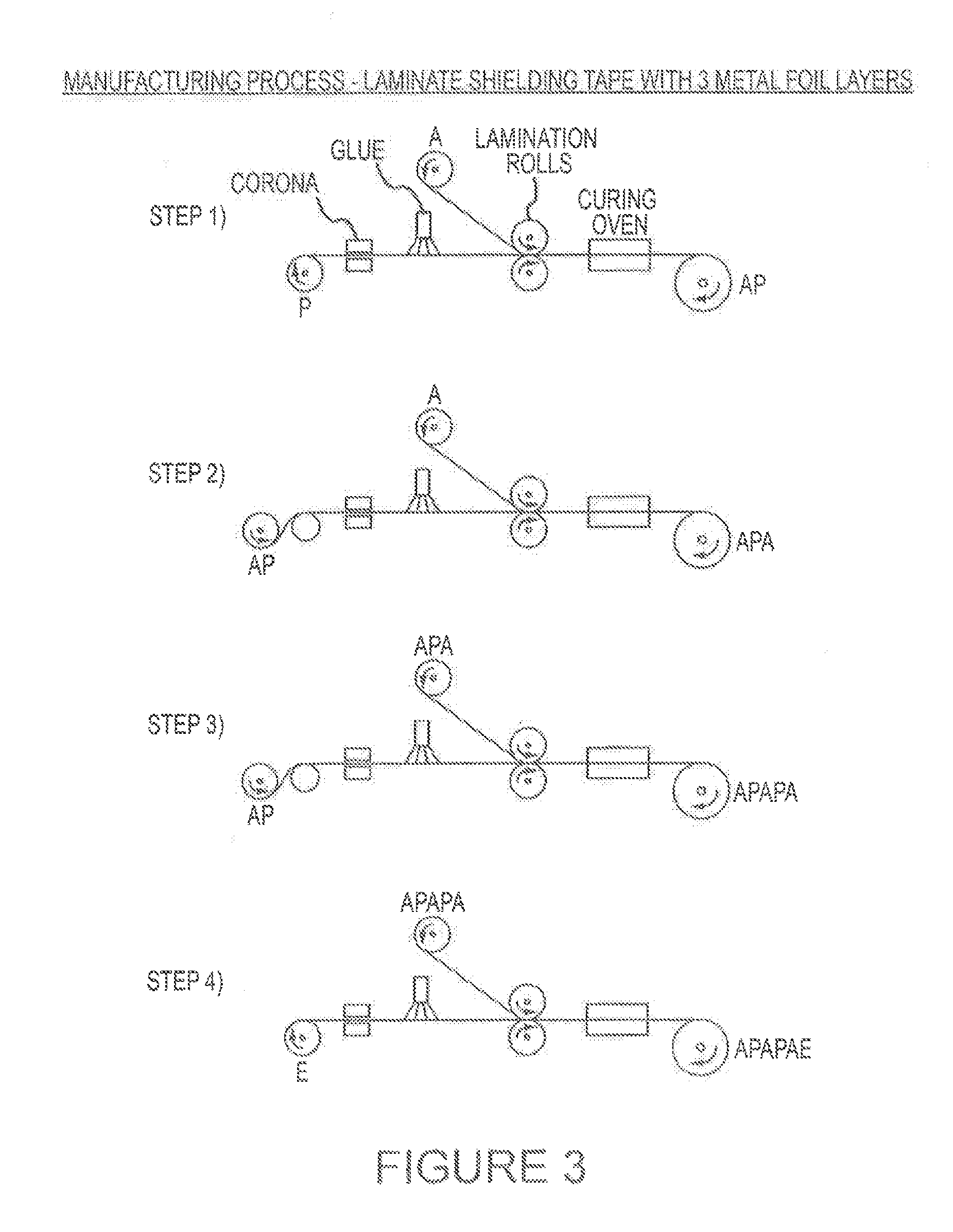
FIG. 3 shows diagrams illustrating how a shielding tape according to the invention is manufactured.
FIG. 4 is a graph depicting the improved performance of a preferred embodiment of the invention over a shielding tape having two shielding layers.
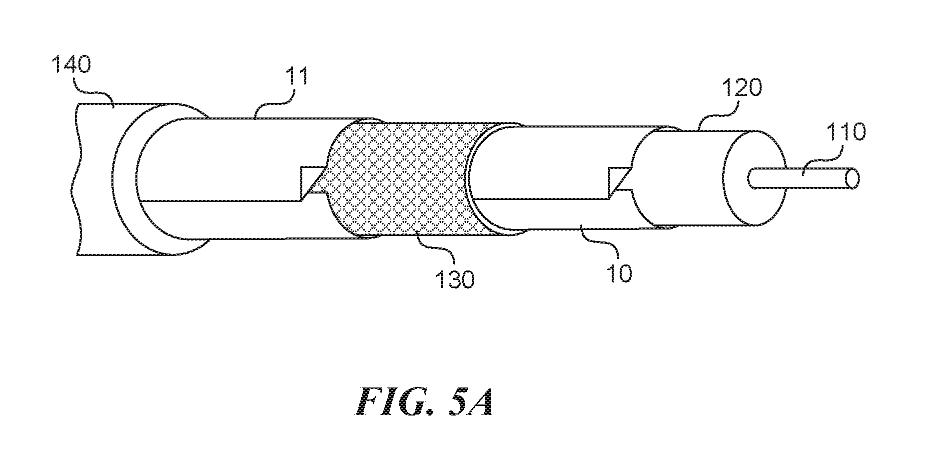
FIG. 5A shows a side perspective view of a tri-shield coaxial cable having an additional layer of shielding tape configured in accordance with the present technology.
FIG. 5B shows a side perspective view of a quad-shield coaxial cable configured in accordance with the present technology.
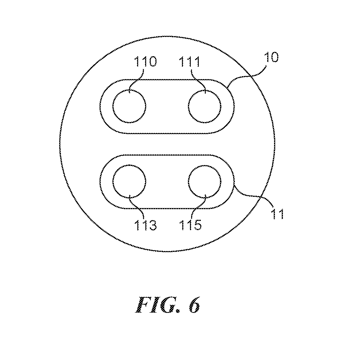
FIG. 6 shows a cross-sectional end view of a cable having a first center conductor and a second center conductor surrounded by a shielding tape configured in accordance with the present technology.
FIG. 7 shows a cross-sectional view of shielding tape having four shielding layers configured in accordance with the present technology.
DESCRIPTION OF PREFERRED EMBODIMENTS OF THE INVENTION
Turning now to the drawings, where the purpose is to describe preferred embodiments of the invention and not limit same, FIG. 1 shows a shielding tape 10.
Shielding tape 10 according to the present invention comprises at least three layers of shielding material (which are also called "shielding layers"). As shown in FIG. 1, the shielding tape 10 comprises a laminate structure of aluminum 20/PET 30/aluminum 40/PET 50/aluminum 60, with a hot melt adhesive 70 (which is preferably EAA or EMAA) applied to aluminum layer 60.
The aluminum layers of the exemplary shielding tape 10 are each about 9 microns thick, while the separating layers are about 12 microns thick. There is also a layer of adhesive between each aluminum/PET layer of about 2 microns thick. The adhesive layer 70 is about 25 microns thick. Other embodiments of the present invention may include shielding layers of at least 3 microns thick, separating layers of at least 4 microns thick, and adhesive layers of at least 8 microns thick. Multiple shielding layers need not all be of the same thickness. Likewise, multiple separating layers and/or adhesive layers need not all have the same thickness.
The layers of shielding material may comprise any suitable material, such as aluminum, copper, silver, a magnetic alloy (such as Mu-metal), or combinations thereof, and need not each be formed from the same material(s). The shielding layers may be any suitable thickness, and need not each be the same thickness. Additionally, while the exemplary shielding tape depicted in FIG. 1 comprises three shielding layers, alternate embodiments of the present invention may include any suitable number of shielding layers greater than two, such as four or more layers of shielding material, each separated by a separator material. For example, FIG. 7 shows a shielding tape 10 comprising a first shielding layer 20 bonded to a first separating layer 30, and a second shielding layer 40 bonded to the first separating layer 30 and a second separating layer 50. The tape further comprises a third shielding layer 60 bonded to the second separating layer 50 and a third separating layer 61, as well as a fourth shielding layer 63 bonded to the third separating layer 61.
The separator layers are preferably plastic and may comprise any suitable material, such as polyester, polyethylene terephthalate ("PET"), a polyolefin (such as polypropylene), or combinations thereof, and need not each be formed from the same material(s). The separator layers may be any suitable thickness, and need not each be the same thickness. Additionally, while the exemplary shielding tape depicted in FIG. 1 comprises two plastic layers, each disposed between two of the three respective shielding layers, alternate embodiments of the present invention may include any suitable number of plastic layers.
The additional thickness of the shielding tape of the present invention can be accommodated by, for example, reducing slightly the diameter of the foam dielectric 120 to which it is applied. This allows the diameter of the cable 100 to remain the same as conventional cables, yet the slight reduction in the diameter of the dielectric does not substantially degrade the performance of the cable.
Because of the improved inner layer shielding, a bi-shield coaxial cable using the preferred shielding tape of the present invention (which has three shielding layers) can perform as well as some conventional tri-shield cables without the use of an outer shielding tape. This lowers the cost and complexity of manufacturing the cable. Additionally, connector attachment is easier since an outer shielding layer would normally need to be removed to install a connector. Likewise, a tri-shield coaxial cable using the preferred shielding tape of the present invention (which has three shielding layers) can perform as well as some quad-shield cables without the use of an outer shielding braid. Accordingly, the present invention provides cost savings (e.g., when a bi-shield cable of the present invention is used instead of a conventional tri-shield cable) and/or an improvement in shielding performance (e.g., when a tri-shield cable of the present invention is used instead of a conventional tri-shield cable).
The shielding tape of the present invention also provides additional resistance to performance degradation due to wear. Upon repeated flexing of conventional cables, the shielding material (which is preferably aluminum) in each shielding layer can develop micro-cracks. These degrade shielding performance because the cracks in one shielding layer may align with the cracks in the other shielding layer, and RF can then egress or ingress through the cracks in each respective layer. The present invention reduces the effects of such cracks because cracks in each of the three layers are less likely to be aligned to provide a path for R.F. egress or ingress as compared to shielding tape with only one or two shielding layers. This is illustrated in FIG. 4.
The exemplary bi-shield coaxial cable 100 in FIG. 2 comprises a center conductor 110 preferably formed from copper-clad steel and is about 0.0403'' in diameter. The center conductor 110 may be any suitable diameter or thickness, such as between about 0.014'' and about 0.200'' in diameter. The center conductor 110 may also be formed from any other suitable conductive material, such as copper, copper-plated steel, and/or copper-plated aluminum. The center conductor 110 may be solid or may comprise multiple conductors, such as stranded wire. Surrounding the center conductor 110 is a dielectric 120 that is about 0.18'' in diameter and preferably formed from foam polyethylene. The dielectric may be any suitable diameter, such as between about 0.040'' and about 0.600'' in diameter. The dielectric 120 may also be solid, and may be formed from any other suitable material, such as polypropylene or fluorinated ethylene propylene. The shielding tape 10 of the present invention is wrapped around, and preferably bonded (using an adhesive) to the dielectric 120. Surrounding the shielding tape 10 is a braid 130 preferably formed from 34-gauge aluminum wire. The braid 130 may be formed from any other suitable material, such as aluminum, copper, copper-plated steel, tinned copper, and/or copper-clad steel. An outer jacket 140 formed from polyvinyl chloride ("PVC") that is about 0.273'' in diameter and about 0.03'' thick surrounds the outer foil. The jacket 140 may be any suitable thickness, such as between about 0.007'' and 0.080'' thick. The jacket 140 may also be formed from any other flexible insulator, such as polyethylene, nylon, and/or TEFLON. The dimensions recited above are for an RG-6 type 75-Ohm coaxial cable, but the shielding tape of the present invention may be used with any other form of cable having components of any suitable dimension, such as 50-Ohm coaxial cables.
Cables employing shielding tape of the present invention may also include additional layers of shielding tape and/or braid. For example, as shown in FIG. 5A, a tri-shield coaxial cable may include an additional layer of shielding tape 11 surrounding the braid 130, providing three layers of shielding (the outer foil 11, the braid 130, and the inner foil 10). The outer foil 11 may employ conventional shielding tape or the shielding tape of the present invention. In another example shown in FIG. 5B, the present invention may be used in conjunction with a quad-shield coaxial cable, which includes an outer foil layer 11 (as described above for the tri-shield cable) and an outer braid 131 surrounding the outer foil layer 11 to provide four layers of shielding.
A shielding tape of the present invention may be used in conjunction with any other type of shielded cable, such as shielded twisted-pair ("STP") cabling. In an STP cable, for example, the shielding tape of the present invention may be used to surround each pair of one or more pairs of conductors twisted together. As shown in FIG. 6, in some embodiments the cable may have a first conductor 110 and a second conductor 111 surrounded by a first shielding tape 10. In yet other embodiments, the cable may also have third and fourth conductors, 113 and 115, respectively, surrounded by a second shielding tape 11. A shielding tape of the present invention may be used to surround any type of conductor, insulator, or other component of a shielded cable and may surround a conductor directly (i.e., there are no intervening structures between the conductor and the tape) or indirectly (i.e., there are one or more intervening structures between the conductor and the tape, such as a dielectric, braiding, or other shielding).
An exemplary process for manufacturing a shielding tape in accordance with the present invention is depicted in FIG. 3. In this process, lamination is used to bond multiple layers of materials into a sandwich structure. These materials are processed in the form of wide (typically 0.5 to 2 meters) and long (typically 1,000 to 50,000 meters) sheet. After all of the lamination layers are combined, the sheet is slit into multiple narrow tapes (typically 10 mm to 50 mm wide) and rolled up for use in manufacturing cable. The shielding tape contains metallic and polymeric strengthening layers interspersed with adhesive layers. An optional hot melt adhesive can be applied to one side of the laminate to bond it to a cable core. The desired tape construction is: A/P/A/P/A/E where A=aluminum, P=polyester and E=EMAA (a hot melt adhesive). This process can also be used to make other shield tape embodiments where A=other metal such as copper, lead or Mu metal and P=other polymers such as polypropylene and E=other adhesives such as EAA.
Referring again to FIG. 3, in step (1), polyester (P) and aluminum (A) sheets are fed from rolls into the laminator. Before lamination the polyester surface may be activated using a corona treatment whereby the sheet is passed through a high voltage corona discharge etching the surface to make the adhesive bond more effective. Next a thin layer (about 2 microns) of liquid adhesive is applied to the polyester sheet by spraying or by offset printing. The lamination rolls apply pressure and heat to bond the two sheets together. An oven is used to heat and cure the adhesive. The AP laminate is then rolled up for the next operation.
In step (2), the AP sheet and an A sheet are fed from rolls into the laminator. Once again, corona treatment may be used to activate the P surface prior to applying a thin layer of liquid adhesive. After lamination and oven curing the APA laminate is rolled up for the next operation.
In step (3), the sheet of AP manufactured in step 1 is combined with a sheet of APA manufactured in step 2 using lamination resulting in an APAPA layer, which is rolled up. This laminate with 3 metal shielding layers can be slit and used as is if no hot melt adhesive layer is needed.
In step (4), the sheet of APAPA manufactured in step 3 is combined with a sheet of E using the laminator. The E surface may be activated using corona treatment to improve adhesive bonding. After lamination and oven curing the APAPAE laminate is rolled up for slitting.
In step (5), the sheet of APAPA or APAPAE is slit into multiple tapes to the final width and then rolled up for use in cable manufacture.
As mentioned previously, the laminate shielding tape of the present invention provides better shielding effectiveness than cables with conventional tape, even after repeated flexing of the cable. This effectiveness is illustrated in the graph in FIG. 4.
Having thus described preferred embodiments of the invention, other variations and embodiments that do not depart from the spirit of the invention will become apparent to those skilled in the art. The scope of the present invention is thus not limited to any particular embodiment, but is instead set forth in the appended claims and the legal equivalents thereof. Unless expressly stated in the written description or claims, the steps of any method recited in the claims may be performed in any order capable of yielding the desired result.
* * * * *
References
D00000
D00001
D00002
D00003
D00004
D00005
D00006
D00007
XML
uspto.report is an independent third-party trademark research tool that is not affiliated, endorsed, or sponsored by the United States Patent and Trademark Office (USPTO) or any other governmental organization. The information provided by uspto.report is based on publicly available data at the time of writing and is intended for informational purposes only.
While we strive to provide accurate and up-to-date information, we do not guarantee the accuracy, completeness, reliability, or suitability of the information displayed on this site. The use of this site is at your own risk. Any reliance you place on such information is therefore strictly at your own risk.
All official trademark data, including owner information, should be verified by visiting the official USPTO website at www.uspto.gov. This site is not intended to replace professional legal advice and should not be used as a substitute for consulting with a legal professional who is knowledgeable about trademark law.