Tornado display
Shafer , et al. Sept
U.S. patent number 10,421,579 [Application Number 15/679,701] was granted by the patent office on 2019-09-24 for tornado display. The grantee listed for this patent is General Packaging Products, Inc.. Invention is credited to Robert Berg, Michael Shafer.


| United States Patent | 10,421,579 |
| Shafer , et al. | September 24, 2019 |
Tornado display
Abstract
A blank of material to be folded into a product display container is disclosed. The blank is substantially rectangular in shape and has a first edge, a second edge opposite of the first edge, a third edge disposed adjacent to the first edge and the second edge and a fourth edge disposed opposite the third edge. The blank comprises a tab disposed adjacent to the fourth edge; a plurality of perpendicular folds, wherein each perpendicular fold extends across the width of the blank and is disposed substantially perpendicular to the first edge and the second edge; and a plurality of angular folds, wherein each angular fold extends across the width of the blank and is disposed at a non-perpendicular angle with respect to the first edge and the second edge. The blank is utilized to make a tornado shaped product display.
| Inventors: | Shafer; Michael (Wadsworth, OH), Berg; Robert (Wadsworth, OH) | ||||||||||
|---|---|---|---|---|---|---|---|---|---|---|---|
| Applicant: |
|
||||||||||
| Family ID: | 61190619 | ||||||||||
| Appl. No.: | 15/679,701 | ||||||||||
| Filed: | August 17, 2017 |
Prior Publication Data
| Document Identifier | Publication Date | |
|---|---|---|
| US 20180050836 A1 | Feb 22, 2018 | |
Related U.S. Patent Documents
| Application Number | Filing Date | Patent Number | Issue Date | ||
|---|---|---|---|---|---|
| 62375930 | Aug 17, 2016 | ||||
| Current U.S. Class: | 1/1 |
| Current CPC Class: | A47F 5/112 (20130101); B65D 5/4266 (20130101); B65D 5/04 (20130101); B65D 5/5213 (20130101); B65D 5/029 (20130101) |
| Current International Class: | B65D 5/42 (20060101); B65D 5/02 (20060101); A47F 5/11 (20060101); B65D 5/52 (20060101); B65D 5/04 (20060101) |
| Field of Search: | ;229/116.1 |
References Cited [Referenced By]
U.S. Patent Documents
| 1896721 | February 1933 | Richards |
| 2150453 | March 1939 | Mulford |
| 2176912 | October 1939 | Luckett |
| D178925 | October 1956 | March |
| 3079062 | February 1963 | Craddock |
| 3237838 | March 1966 | Elias |
| 3269644 | August 1966 | Bump |
| 3447732 | June 1969 | Deckys |
| 3844470 | October 1974 | Rohde |
| 3912156 | October 1975 | May |
| 4017017 | April 1977 | Vos |
| 4063679 | December 1977 | Henry |
| 4191324 | March 1980 | Kitagawa |
| 4260097 | April 1981 | Nold |
| 4408689 | October 1983 | Daniels |
| 4691858 | September 1987 | Peer, Jr. |
| 4792470 | December 1988 | Clark |
| 5098014 | March 1992 | Perkins |
| D391097 | February 1998 | Eichert |
| 5791555 | August 1998 | Kanter |
| 5819453 | October 1998 | Eichert |
| 6206279 | March 2001 | Countee |
| D525762 | August 2006 | Evans |
| D549587 | August 2007 | Lestelle |
| D560377 | January 2008 | Jouin |
| D566573 | April 2008 | Lestelle |
| D586208 | February 2009 | Evans |
| D592051 | May 2009 | Casebasse |
| D646721 | October 2011 | Dingler |
| 8479972 | July 2013 | Craft |
| 10022943 | July 2018 | Scharfenort |
Attorney, Agent or Firm: Keener; Kevin Keener and Associates, P.C.
Parent Case Text
PRIORITY
This application claims priority to U.S. Provisional Application Ser. No. 62/375,930, filed on Aug. 17, 2017, the disclosure of which is hereby incorporated by reference.
Claims
The invention claimed is:
1. A blank of material to be folded into a product display container a) wherein said blank is substantially rectangular in shape having a first edge, a second edge opposite of said first edge, a third edge disposed adjacent to said first edge and said second edge and a fourth edge disposed opposite said third edge; i) wherein said first edge and said second edge extend along a length of said blank; ii) wherein said third edge and said fourth edge extend along a width of said blank; b) said blank comprising i) a tab disposed adjacent to said fourth edge; ii) a first surface and a second surface disposed on an opposite side from said first surface; iii) a plurality of perpendicular folds, wherein each perpendicular fold extends across said width of said blank for an entire distance from said first edge to said second edge and is disposed substantially perpendicular to said first edge and said second edge; iv) a plurality of angular folds, wherein each angular fold extends across said width of said blank for an entire distance from said first edge to said second edge and is disposed at a non-perpendicular angle with respect to said first edge and said second edge; v) wherein a first end of each angular fold is disposed at a first end of a first respective perpendicular fold along said first edge; vi) wherein a second end of each of said angular folds is disposed at a second end of a second respective perpendicular fold along said second edge; vii) wherein each of said angular folds project outward from said first surface; and viii) wherein each of said perpendicular folds project outward from said second surface.
2. The blank as in claim 1 further comprising four angular folds.
3. The blank as in claim 2 further comprising four perpendicular folds.
4. The blank as in claim 3 further comprising one or more apertures.
5. The blank as in claim 3 wherein said blank is formed from cardboard.
6. The blank as in claim 1 further comprising four perpendicular folds.
7. The blank as in claim 1 further comprising one or more apertures.
8. The blank as in claim 1 wherein said blank is formed from cardboard.
Description
FIELD OF THE INVENTION
This application pertains generally to product displays and more particularly to a specialized blank and product display.
BACKGROUND OF INVENTION
Different product displays are known. A conventional product display is no more than an open box in a cuboid shape with a vertical back displaying information regarding the product. This configuration has simple functionality but lacks distinctiveness required to gain a customer's attention in today's retail location. What is needed is a distinctive product display which functions to hold products but has a unique and distinctive shape to grab the attention of consumers.
SUMMARY OF THE INVENTION
The following presents a simplified summary in order to provide a basic understanding of some aspects of the disclosed innovation. This summary is not an extensive overview, and it is not intended to identify key/critical elements or to delineate the scope thereof. Its sole purpose is to present some concepts in a simplified form as a prelude to the more detailed description that is presented later.
The invention is directed to a blank of material to be folded into a product display container. The blank is substantially rectangular in shape and has a first edge, a second edge opposite of the first edge, a third edge disposed adjacent to the first edge and the second edge and a fourth edge disposed opposite the third edge. The first edge and the second edge extend along a length of the blank. The third edge and the fourth edge extend along a width of the blank. The blank comprises a tab disposed adjacent to the fourth edge; a plurality of perpendicular folds, wherein each perpendicular fold extends across the width of the blank and is disposed substantially perpendicular to the first edge and the second edge; and a plurality of angular folds, wherein each angular fold extends across the width of the blank and is disposed at a non-perpendicular angle with respect to the first edge and the second edge. A first end of each angular fold is disposed at a first end of a first respective perpendicular fold along the first edge. A second end of each of the angular folds is disposed at a second end of a second respective perpendicular fold along the second edge.
The blank may comprise four angular folds. The blank may comprise four perpendicular folds. The blank may further comprise one or more apertures.
The blank may further comprise a first surface and a second surface disposed on an opposite side from the first surface. Each of the angular folds project outward from the first surface. Each of the perpendicular folds project outward from the second surface.
Still other embodiments of the present invention will become readily apparent to those skilled in this art from the following description wherein there is shown and described the embodiments of this invention, simply by way of illustration of the best modes suited to carry out the invention. As it will be realized, the invention is capable of other different embodiments and its several details are capable of modifications in various obvious aspects all without departing from the scope of the invention. Accordingly, the drawing and descriptions will be regarded as illustrative in nature and not as restrictive.
BRIEF DESCRIPTION OF THE DRAWINGS
Various exemplary embodiments of this invention will be described in detail, wherein like reference numerals refer to identical or similar components, with reference to the following figures, wherein:
FIG. 1 is a blank of the product display;
FIG. 2 is a side perspective view of the product display; and
FIG. 3 is a top perspective view of the product display.
DETAILED DESCRIPTION OF THE PREFERRED EMBODIMENT
The claimed subject matter is now described with reference to the drawings. In the following description, for purposes of explanation, numerous specific details are set forth in order to provide a thorough understanding of the claimed subject matter. It may be evident, however, that the claimed subject matter may be practiced with or without any combination of these specific details, without departing from the spirit and scope of this invention and the claims.
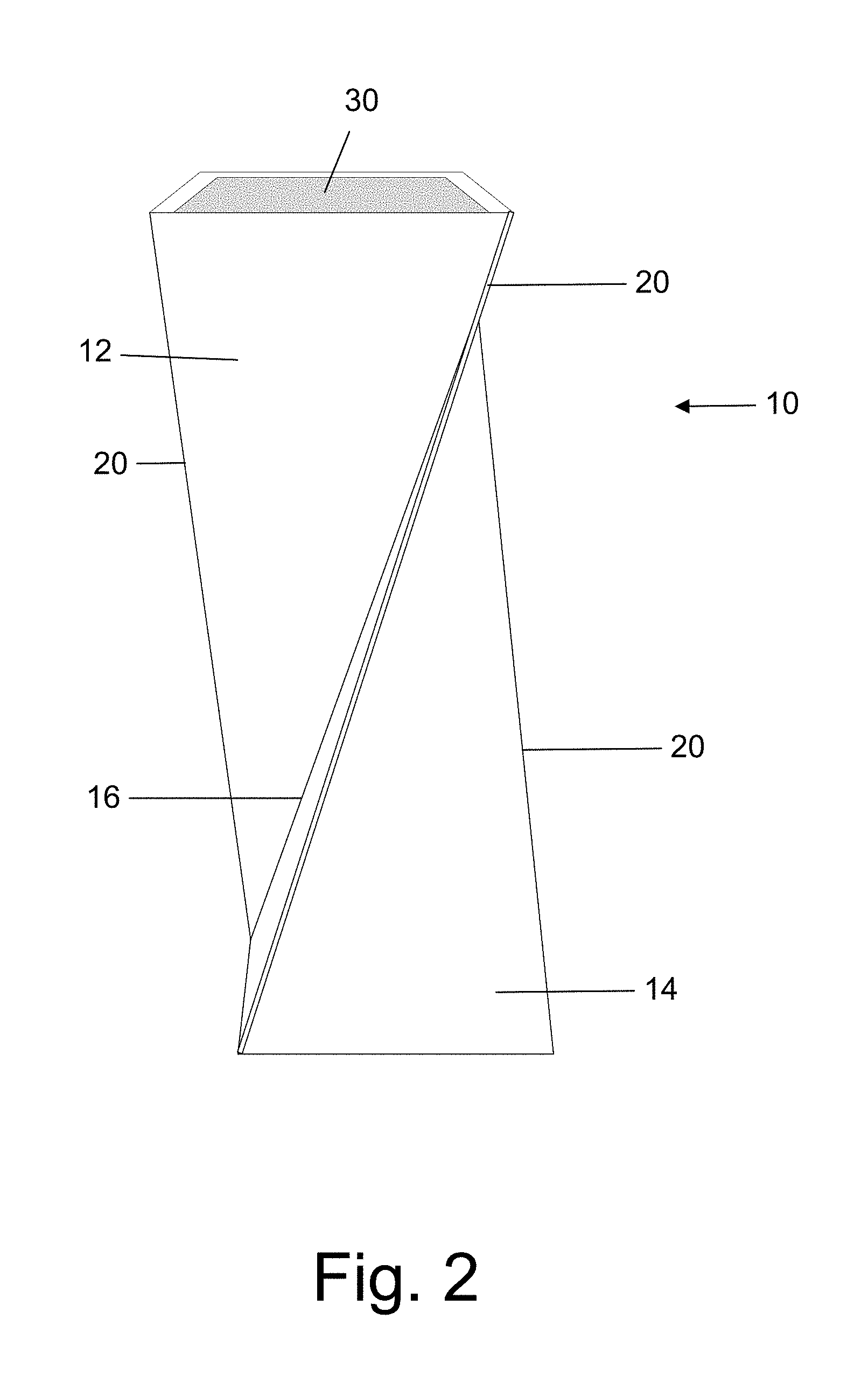
The invention is directed toward a foldable blank for a product display and a folded product display. Referring to FIG. 1, the preferred embodiment of the display blank 10 is illustrated. The display blank 10 may be made from any material. In the preferred embodiment the display blank 10 is composed of cardboard. In other embodiments, the display blank 10 is made from a thermoplastic material, metal, paper, or any other commercially available structural material. In the preferred embodiment the display blank 10 is an elongate rectangular sheet of thin material which can be folded into the specific shape of the product display. The display blank 10 may be any size, thickness, length, width, or shape.
In the preferred embodiment the display blank 10 has a plurality of plurality of upper triangles 12. The upper triangles 12 may be any size or shape. The preferred embodiment also has a plurality of lower triangles 14. The lower triangles 14 may be any size or shape. In one portion of the display blank 10, the upper triangle 12 is connected to the lower triangle 14 by a shared hypotenuse 16. The shared hypotenuse 16 may be a fold point in the material. In another embodiment the shared hypotenuse 16 is a perforation in the material. The shared hypotenuse 16 is at a predetermined angle to the width of the display blank 10. Each hypotenuse 16 may be at a separate predetermined angle to the width of the display blank 10. In the preferred embodiment each hypotenuse 16 is at the same predetermined angle.
In another portion the of the display blank 10, the lower triangle 14 is connected to a second upper triangle 12 by a shared side 20. The shared side 20 is parallel to the width of the display blank 10. The shared side 20 may be a fold in the material. In another embodiment the shared side 20 is a perforation in the material.
At one end of the display blank 10 is a tab 18. The tab 18 may be any size and shape. In other embodiments there are a plurality of tabs 18. The tab 18 is utilized to permit the display blank 10 to be folded into a three-dimensional shape. In the three-dimensional shape the tab 18 is glued to the opposite end of the display blank 10. The tab 18 may be secured to the opposite end of the display blank 10 in any manner of known means, such as glue, staples, tape, ultrasonic welding, heat sealing, or any other commercially available means.
In the preferred embodiment the display blank 10 has four upper triangles 12 and four lower triangles 14. In other embodiments there may be any number of upper triangles 12 and lower triangles 14. The number of upper triangles 12 and lower triangles 14 determines the ultimate number of sides of the folded product display.
Referring to FIG. 2 and FIG. 3, the folded, three-dimensional configuration of the product display is illustrated. In the folded, three-dimensional configuration the product display has inner diagonal lines formed by each hypotenuse 16. The inner diagonal lines formed by each hypotenuse 16 extend laterally into the body of the display. The product display has outer diagonal extensions formed by the shared sides 20. The outer diagonal extensions formed by the shared sides 20 extend laterally outward from the body of the display.
The product display has a lower pyramid shape to provide a standing base for the product display. The product display has an upper inverted pyramid shape to hold the selected product. The product display has an internal holding portion 30 which is utilized to hold any chosen product. In the preferred embodiment, the product display is utilized to hold loose material. In other embodiments products may be in specialized shape boxes to complement the shape of the product display.
In the preferred embodiment shown in FIG. 2 and FIG. 3, the top of the product display has a square cross sectional shape. The bottom end of the product display also has a square cross sectional shape. In the folded configuration, a corner of the top square is connected to the corner of the bottom square that is rotated ninety degrees from the corner of the top square by the outer diagonal extension formed by a shared side 20. The same corner of the top square is also connected to the corner of the bottom square that is rotated one hundred eighty degrees from the corner of the top square by the inner diagonal line formed by a hypotenuse 16.
In some embodiments of the invention any upper triangle 12 and any lower triangle 14 may have sections cut out from the middle, thereby creating a hole through which materials and products may be inserted or withdrawn from the product display.
In the preferred embodiment there are four upper triangles 12 and four lower triangles 14. The number of upper triangles 12 and lower triangles 14 determine the number of sides of the folded product display. In the preferred embodiment the product display has a square cross section. In other embodiments the blank may have more than four upper triangles 12 and more than four lower triangles 14. The additional upper triangles 12 and lower triangles 14 changes the cross sectional shape of the product display such that the cross sectional shape may be any polyhedron shape.
What has been described above includes examples of the claimed subject matter. It is, of course, not possible to describe every conceivable combination of components or methodologies for purposes of describing the claimed subject matter, but one of ordinary skill in the art can recognize that many further combinations and permutations of such matter are possible. Accordingly, the claimed subject matter is intended to embrace all such alterations, modifications and variations that fall within the spirit and scope of the appended claims. Furthermore, to the extent that the term "includes" is used in either the detailed description or the claims, such term is intended to be inclusive in a manner similar to the term "comprising" as "comprising" is interpreted when employed as a transitional word in a claim.
The foregoing method descriptions and the process flow diagrams are provided merely as illustrative examples and are not intended to require or imply that the steps of the various embodiments must be performed in the order presented. As will be appreciated by one of skill in the art the order of steps in the foregoing embodiments may be performed in any order. Words such as "thereafter," "then," "next," etc. are not intended to limit the order of the steps; these words are simply used to guide the reader through the description of the methods. Further, any reference to claim elements in the singular, for example, using the articles "a," "an" or "the" is not to be construed as limiting the element to the singular.
The preceding description of the disclosed embodiments is provided to enable any person skilled in the art to make or use the present invention. Various modifications to these embodiments will be readily apparent to those skilled in the art, and the generic principles defined herein may be applied to other embodiments without departing from the spirit or scope of the invention. Thus, the present invention is not intended to be limited to the embodiments shown herein but is to be accorded the widest scope consistent with the following claims and the principles and novel features disclosed herein.
* * * * *
D00000
D00001
D00002
D00003
XML
uspto.report is an independent third-party trademark research tool that is not affiliated, endorsed, or sponsored by the United States Patent and Trademark Office (USPTO) or any other governmental organization. The information provided by uspto.report is based on publicly available data at the time of writing and is intended for informational purposes only.
While we strive to provide accurate and up-to-date information, we do not guarantee the accuracy, completeness, reliability, or suitability of the information displayed on this site. The use of this site is at your own risk. Any reliance you place on such information is therefore strictly at your own risk.
All official trademark data, including owner information, should be verified by visiting the official USPTO website at www.uspto.gov. This site is not intended to replace professional legal advice and should not be used as a substitute for consulting with a legal professional who is knowledgeable about trademark law.