Transparent liquid crystal display on display case
Dunn Sept
U.S. patent number 10,417,943 [Application Number 15/882,817] was granted by the patent office on 2019-09-17 for transparent liquid crystal display on display case. This patent grant is currently assigned to Manufacturing Resources International, Inc.. The grantee listed for this patent is Manufacturing Resources International, Inc.. Invention is credited to William Dunn.


| United States Patent | 10,417,943 |
| Dunn | September 17, 2019 |
Transparent liquid crystal display on display case
Abstract
A point-of-sale advertising system for use with a display case having a front glass sheet positioned in front of a cavity for accepting goods, the system containing a transparent LCD positioned behind the front glass sheet, and a plurality of LEDs positioned adjacent to one pair of opposing edges of the LCD and arranged so that light which is emitted from the LEDs is directed backwards towards the cavity. Further embodiments may also contain a door assembly and frame surrounding the front glass sheet and LCD, a switch positioned to determine when the door assembly is open or closed, and electrical circuitry adapted to turn off the LEDs when the door is open and turn on the LEDs when the door is closed.
| Inventors: | Dunn; William (Alpharetta, GA) | ||||||||||
|---|---|---|---|---|---|---|---|---|---|---|---|
| Applicant: |
|
||||||||||
| Assignee: | Manufacturing Resources
International, Inc. (Alpharetta, GA) |
||||||||||
| Family ID: | 49324768 | ||||||||||
| Appl. No.: | 15/882,817 | ||||||||||
| Filed: | January 29, 2018 |
Prior Publication Data
| Document Identifier | Publication Date | |
|---|---|---|
| US 20180151097 A1 | May 31, 2018 | |
Related U.S. Patent Documents
| Application Number | Filing Date | Patent Number | Issue Date | ||
|---|---|---|---|---|---|
| 13649764 | Oct 11, 2012 | 9881528 | |||
| 61546809 | Oct 13, 2011 | ||||
| Current U.S. Class: | 1/1 |
| Current CPC Class: | G09G 3/18 (20130101); G09F 23/065 (20130101); G09F 23/0058 (20130101); G09F 23/06 (20130101); G02F 1/13 (20130101); G09F 9/35 (20130101); G09F 2023/0025 (20130101) |
| Current International Class: | G02F 1/13 (20060101); G09G 3/18 (20060101); G09F 9/35 (20060101); G09F 23/06 (20060101); G09F 23/00 (20060101) |
References Cited [Referenced By]
U.S. Patent Documents
| 3629972 | December 1971 | Rehberg et al. |
| 4040726 | August 1977 | Paca |
| 4299092 | November 1981 | Ibrahim |
| 4371870 | February 1983 | Biferno |
| 4853678 | August 1989 | Bishop, Jr. et al. |
| 4950344 | August 1990 | Glover et al. |
| 7413233 | August 2008 | Jung |
| 7455412 | November 2008 | Rottcher |
| 7513637 | April 2009 | Kelly et al. |
| 7922381 | April 2011 | Han et al. |
| 8254121 | August 2012 | Lee et al. |
| 8417376 | April 2013 | Smolen |
| 8578081 | November 2013 | Fils |
| 8683745 | April 2014 | Artwohl et al. |
| 8982013 | March 2015 | Sako et al. |
| 8988635 | March 2015 | Dunn et al. |
| 9052536 | June 2015 | Artwohl et al. |
| 9155405 | October 2015 | Artwohl et al. |
| 9173509 | November 2015 | Mischel, Jr. et al. |
| 9500801 | November 2016 | Dunn |
| 9500896 | November 2016 | Dunn et al. |
| 9514661 | December 2016 | Riegel |
| 9519185 | December 2016 | Dunn et al. |
| 9526352 | December 2016 | Dunn et al. |
| 9535293 | January 2017 | Dunn |
| 9633366 | April 2017 | Dunn |
| 9661939 | May 2017 | Dunn et al. |
| 9684124 | June 2017 | Dunn |
| 9733420 | August 2017 | Dunn et al. |
| 9832847 | November 2017 | Dunn et al. |
| 9881528 | January 2018 | Dunn |
| 9983427 | May 2018 | Dunn |
| 10052026 | August 2018 | Tran |
| 2002/0064037 | May 2002 | Lee |
| 2002/0075552 | June 2002 | Poll et al. |
| 2002/0187575 | December 2002 | Maruyama et al. |
| 2003/0062813 | April 2003 | Cording |
| 2003/0117790 | June 2003 | Lee et al. |
| 2003/0139169 | July 2003 | Arreazola, Jr. |
| 2004/0148055 | July 2004 | Shoenfeld |
| 2004/0160388 | August 2004 | O'Keeffe |
| 2005/0195972 | September 2005 | Barr |
| 2005/0265019 | December 2005 | Sommers et al. |
| 2006/0012985 | January 2006 | Archie, Jr. et al. |
| 2006/0215958 | September 2006 | Yeo et al. |
| 2006/0284788 | December 2006 | Robinson et al. |
| 2007/0151274 | July 2007 | Roche et al. |
| 2007/0171647 | July 2007 | Artwohl et al. |
| 2007/0195535 | August 2007 | Artwohl et al. |
| 2007/0214812 | September 2007 | Wagner et al. |
| 2008/0024047 | January 2008 | Juo et al. |
| 2008/0042554 | February 2008 | Komoto |
| 2008/0055534 | March 2008 | Kawano |
| 2008/0094854 | April 2008 | Coleman et al. |
| 2008/0284942 | November 2008 | Mahama et al. |
| 2008/0295033 | November 2008 | Lee et al. |
| 2009/0002990 | January 2009 | Becker et al. |
| 2009/0015400 | January 2009 | Breed |
| 2009/0097227 | April 2009 | Kim et al. |
| 2009/0121970 | May 2009 | Ozbek |
| 2009/0225519 | September 2009 | Mischel, Jr. et al. |
| 2009/0244884 | October 2009 | Trulaske, Sr. |
| 2009/0278766 | November 2009 | Sako et al. |
| 2009/0300953 | December 2009 | Frisch et al. |
| 2010/0026912 | February 2010 | Ho |
| 2010/0058628 | March 2010 | Reid et al. |
| 2010/0162747 | July 2010 | Hamel et al. |
| 2010/0238394 | September 2010 | Dunn |
| 2010/0275477 | November 2010 | Kim |
| 2010/0293827 | November 2010 | Suss et al. |
| 2010/0309687 | December 2010 | Sampsell et al. |
| 2011/0056102 | March 2011 | Reid et al. |
| 2011/0083460 | April 2011 | Thomas et al. |
| 2011/0116000 | May 2011 | Dunn et al. |
| 2011/0116231 | May 2011 | Dunn et al. |
| 2011/0261282 | October 2011 | Jean et al. |
| 2012/0020560 | January 2012 | Zarubinsky |
| 2012/0105424 | May 2012 | Lee et al. |
| 2012/0105428 | May 2012 | Fleck et al. |
| 2012/0206500 | August 2012 | Koprowski et al. |
| 2012/0206941 | August 2012 | He |
| 2012/0275477 | November 2012 | Berendt et al. |
| 2012/0285089 | November 2012 | Artwohl et al. |
| 2012/0287368 | November 2012 | Que et al. |
| 2012/0287379 | November 2012 | Koike |
| 2013/0016296 | January 2013 | Fujita et al. |
| 2013/0063326 | March 2013 | Riegel |
| 2013/0063676 | March 2013 | Tsuchihashi et al. |
| 2013/0120815 | May 2013 | Aspnes et al. |
| 2013/0151006 | June 2013 | Garson et al. |
| 2013/0158703 | June 2013 | Lin et al. |
| 2013/0208447 | August 2013 | Maslen |
| 2013/0211583 | August 2013 | Borra |
| 2013/0265525 | October 2013 | Dunn et al. |
| 2013/0271674 | October 2013 | Liu et al. |
| 2013/0271696 | October 2013 | Dunn |
| 2014/0062316 | March 2014 | Tischler et al. |
| 2014/0078407 | March 2014 | Green et al. |
| 2014/0085564 | March 2014 | Hendren et al. |
| 2014/0104538 | April 2014 | Park et al. |
| 2014/0137065 | May 2014 | Feng et al. |
| 2014/0144083 | May 2014 | Artwohl et al. |
| 2014/0204452 | July 2014 | Branson |
| 2014/0285732 | September 2014 | Tanabe et al. |
| 2014/0300979 | October 2014 | Tomida et al. |
| 2014/0333541 | November 2014 | Lee et al. |
| 2015/0035432 | February 2015 | Kendall et al. |
| 2015/0172385 | June 2015 | Kuroyama et al. |
| 2015/0177480 | June 2015 | Bullock et al. |
| 2015/0250021 | September 2015 | Stice et al. |
| 2015/0253612 | September 2015 | Hasegawa et al. |
| 2015/0300628 | October 2015 | Dunn et al. |
| 2015/0309263 | October 2015 | Abovitz et al. |
| 2015/0338715 | November 2015 | Schaefer et al. |
| 2015/0362667 | December 2015 | Dunn |
| 2015/0362768 | December 2015 | Dunn |
| 2015/0362792 | December 2015 | Dunn et al. |
| 2015/0363819 | December 2015 | Dunn |
| 2015/0366083 | December 2015 | Dunn et al. |
| 2016/0037657 | February 2016 | Yoshizumi |
| 2016/0061514 | March 2016 | Seo et al. |
| 2016/0091755 | March 2016 | Dunn |
| 2016/0095450 | April 2016 | Trulaske, Sr. |
| 2016/0103275 | April 2016 | Diaz et al. |
| 2016/0106231 | April 2016 | Dunn et al. |
| 2016/0192451 | June 2016 | Dunn et al. |
| 2017/0010771 | January 2017 | Bernstein et al. |
| 2017/0046991 | February 2017 | Riegel |
| 2017/0053456 | February 2017 | Cho et al. |
| 2017/0068042 | March 2017 | Dunn et al. |
| 2017/0068044 | March 2017 | Dunn |
| 2017/0099960 | April 2017 | Dunn et al. |
| 2017/0108735 | April 2017 | Dunn |
| 2017/0228770 | August 2017 | Dunn |
| 2017/0256115 | September 2017 | Diaz |
| 2017/0329078 | November 2017 | Dunn et al. |
| 2018/0012526 | January 2018 | Dunn et al. |
| 2018/0020847 | January 2018 | Dunn et al. |
| 2018/0035521 | February 2018 | Dunn et al. |
| 2018/0151097 | May 2018 | Dunn |
| 2018/0368240 | December 2018 | Dunn et al. |
| 2015277337 | Dec 2015 | AU | |||
| 2015277337 | Sep 2018 | AU | |||
| 2815355 | May 2012 | CA | |||
| 101949526 | Jan 2011 | CN | |||
| 202815379 | Mar 2013 | CN | |||
| 3155607 | Apr 2017 | EP | |||
| 3422907 | Jan 2019 | EP | |||
| 2008180502 | Aug 2008 | JP | |||
| 2008299660 | Dec 2008 | JP | |||
| 2010171010 | Aug 2010 | JP | |||
| 5173088 | Mar 2013 | JP | |||
| 2017531198 | Oct 2017 | JP | |||
| 1020040045939 | Jun 2004 | KR | |||
| 1020110119360 | Nov 2011 | KR | |||
| 2012004874 | May 2012 | KR | |||
| WO2006055873 | May 2006 | WO | |||
| WO2010116202 | Oct 2010 | WO | |||
| WO2013056109 | Apr 2013 | WO | |||
| WO2014006490 | Jan 2014 | WO | |||
| WO2015195681 | Dec 2015 | WO | |||
| 2016021751 | Feb 2016 | WO | |||
| WO2017151934 | Sep 2017 | WO | |||
| WO2018009399 | Jan 2018 | WO | |||
Other References
|
A Vogler & H. Kunkley, Photochemistry and Beer, Jan. 1982, 3 pages, vol. 59, No. 1. cited by applicant . Dave Roos, How Transmissive Film Works, 2008, 9 Pages. cited by applicant . Pilkington TEC Glass, for the Refrigeration Market, 2002, 2 Pages. cited by applicant. |
Primary Examiner: Duong; Thoi V
Attorney, Agent or Firm: Standley Law Group LLP Standley; Jeffrey S. Norris; Jeffrey C.
Parent Case Text
CROSS-REFERENCE TO RELATED APPLICATIONS
This application is a continuation of U.S. application Ser. No. 13/649,764, filed Oct. 11, 2012, which claims priority to U.S. Provisional Application No. 61/546,809, filed Oct. 13, 2011, each of which is hereby incorporated by reference in its entirety.
Claims
We claim:
1. A display case comprising: a housing that defines a cavity that is adapted to receive goods; a front glass substrate positioned over said cavity; a transparent LCD adapted to produce an image such that an individual may see through said LCD into said cavity, said LCD having a first pair of opposing edges; and a plurality of LEDs adapted to provide lighting for said LCD, said LEDs positioned adjacent to at least one of said first pair of opposing edges of said LCD.
2. The display case of claim 1 wherein said LEDs are configured such that light which is emitted from said LEDs is directed backward toward said cavity.
3. The display case of claim 2 wherein said LEDs are configured such that light which is emitted from said LEDs is primarily directed backward toward said cavity.
4. The display case of claim 2 wherein said LEDs are configured such that light which is emitted from said LEDs is adapted to reflect back toward said LCD to create a backlight for said LCD.
5. The display case of claim 1 wherein: a first set of said LEDs is positioned adjacent to a first one of said opposing edges of said LCD; and a second set of said LEDs is positioned adjacent to a second one of said opposing edges of said LCD.
6. The display case of claim 5 wherein: said LCD has a second pair of opposing edges; and said first pair of opposing edges is longer than said second pair of opposing edges.
7. The display case of claim 5 wherein: said LCD has a second pair of opposing edges; and said first pair of opposing edges is shorter than said second pair of opposing edges.
8. The display case of claim 5 wherein: said LCD has a second pair of opposing edges; a third set of said LEDs is positioned adjacent to a first one of said opposing edges of said second pair; and a fourth set of said LEDs is positioned adjacent to a second one of said opposing edges of said second pair.
9. The display case of claim 1 wherein said first pair of opposing edges are vertical edges of said LCD.
10. The display case of claim 1 wherein said first pair of opposing edges are horizontal edges of said LCD.
11. The display case of claim 1 further comprising a rear glass substrate positioned over said cavity such that said LCD is positioned between said rear glass substrate and said front glass substrate.
12. The display case of claim 1 wherein said LEDs are in line with said at least one of said first pair of opposing edges of said LCD.
13. The display case of claim 1 wherein said LEDs are planar with said LCD.
14. The display case of claim 1 wherein said LEDs abut said at least one of said first pair of opposing edges of said LCD.
15. The display case of claim 1 further comprising a door assembly comprising said front glass substrate and said LCD.
16. The display case of claim 15 further comprising: a switch positioned to determine when said door assembly is open or closed; and electrical circuitry in communication with said switch, said electrical circuitry adapted to turn off said LEDs when said door assembly is open and turn on said LEDs when said door assembly is closed.
17. The display case of claim 1 further comprising: masking around a portion of said front glass substrate; wherein said LEDs are positioned behind said masking.
18. The display case of claim 17 further comprising: a power supply in electrical communication with said LEDs; wherein said power supply is positioned behind said masking.
19. The display case of any of claims 1 to 18 wherein said display case is of a type selected from coolers and freezers.
Description
TECHNICAL FIELD
Embodiments generally relate to a transparent liquid crystal display (LCD) positioned adjacent to the display glass in a display case. Embodiments include a system and method for backlighting the LCD as well.
BACKGROUND OF THE ART
Display cases are used in a number of different retail establishments for illustrating the products that are available for sale. In some instances these display cases may be coolers or freezers which are placed in grocery stores, convenience stores, gas stations, restaurants, or other retail establishments. In other instances these display cases may be non-refrigerated transparent containers used in a jewelry or watch store, bakery, deli, antique shop, sporting goods store, electronics store, or other retail establishments. While the design and appearance of the product itself does provide some point-of-sale (POS) advertising, it has been found that additional advertising at the POS can increase the awareness of a product and in turn create additional sales.
Most retail establishments already contain some POS advertising, and depending on the type of establishment the proprietor may want to limit the amount of `clutter` in the retail area--resulting in a very limited space for additional POS advertising. It has now become desirable to utilize the transparent glass that is typically placed in display cases with additional POS advertising. Most notably, it has been considered that transparent LCDs may be positioned along with the transparent glass and could display additional advertising materials while still allowing a patron to view the products inside the display case.
SUMMARY OF THE EXEMPLARY EMBODIMENTS
One exemplary embodiment provides a transparent LCD within the door of a display case. The LCD may be sandwiched between a pair of glass substrates. A plurality of LEDs may be positioned within the door assembly to provide additional illumination of the interior of the display case, reflecting and refracting off the products within the display case, effectively creating a backlight for the transparent LCD. The assembly may contain a switch so that an electronic controlling unit can detect when the door is open or closed. When closed, the LEDs are illuminated. When open, the LEDs are preferably off, but may be simply reduced in power. In some embodiments the LEDs may remain on even when the door is opened.
Another exemplary embodiment provides a transparent LCD within the front glass assembly of a display case. In these embodiments, the LEDs may remain on whenever the LCD is displaying an image. Here, the LCD may be positioned behind a front glass. In any of the embodiments, the video data for the LCD may be provided by CAT-V cable. Also in any of the embodiments, the LEDs may be positioned along opposing edges of the assembly or along all edges of the assembly.
The foregoing and other features and advantages of the present invention will be apparent from the following more detailed description of the particular embodiments, as illustrated in the accompanying drawings.
BRIEF DESCRIPTION OF THE DRAWINGS
A better understanding of an exemplary embodiment will be obtained from a reading of the following detailed description and the accompanying drawings wherein identical reference characters refer to identical parts and in which:
FIG. 1 is a perspective illustration of a display case containing an exemplary embodiment of the transparent LCD.
FIG. 2 is a sectional view showing the interior of the display case shown in FIG. 1.
FIG. 3 is a rear elevation view of the door assembly from the embodiment shown in FIG. 1.
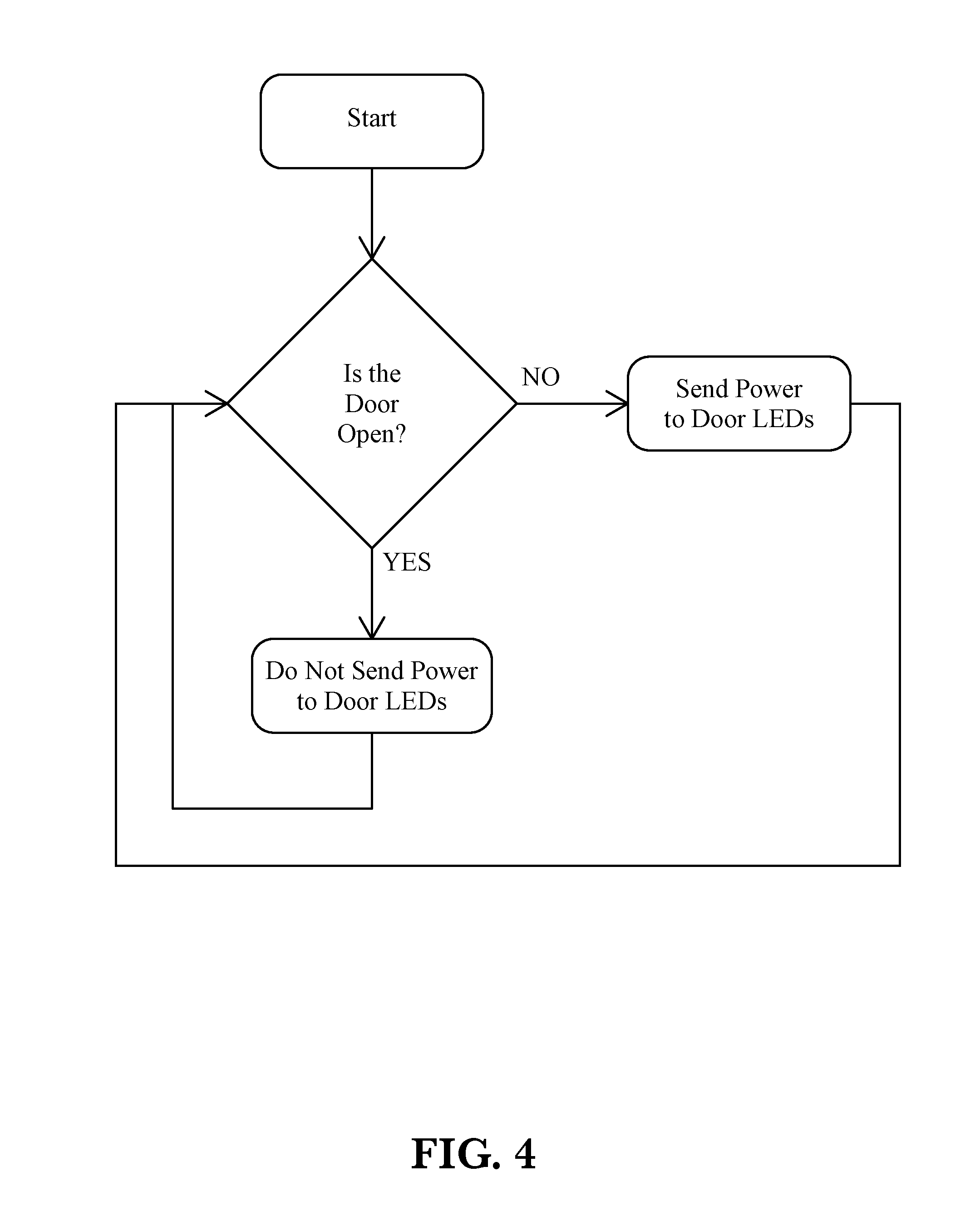
FIG. 4 is a logic flow chart showing one embodiment for controlling the LED lighting for the transparent LCD.
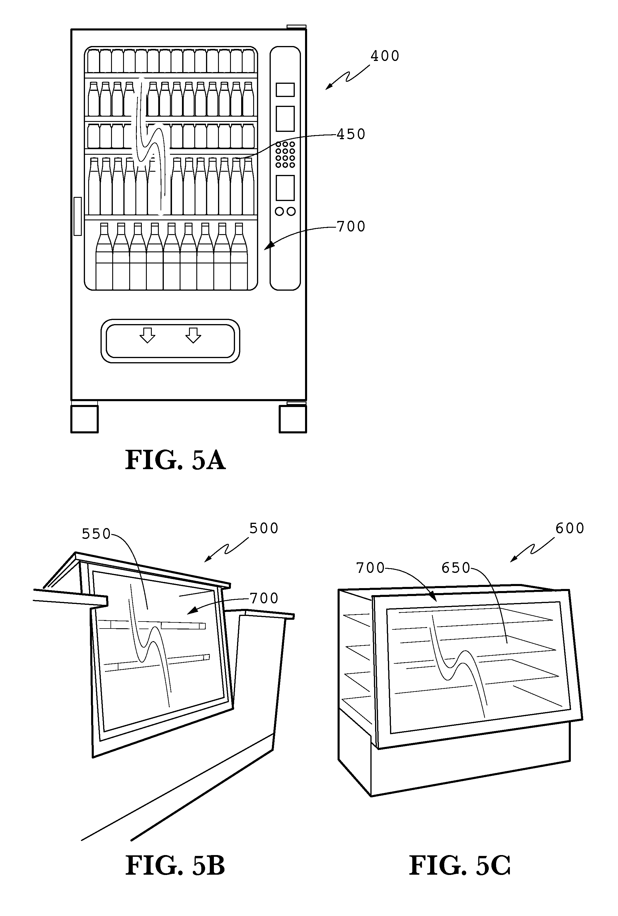
FIG. 5A is an illustration of an embodiment of the transparent LCD used with a vending machine.
FIG. 5B is an illustration of an embodiment of the transparent LCD built within the counter of a general retail establishment.
FIG. 5C is an illustration of an embodiment of the transparent LCD used with a bakery display case.
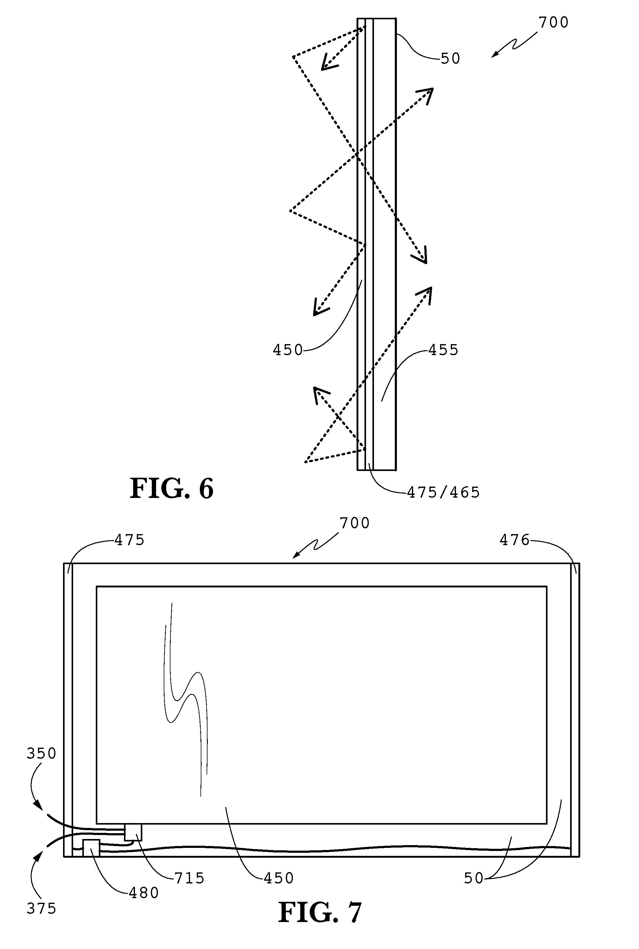
FIG. 6 is a side elevation view of an exemplary front glass assembly.
FIG. 7 is a rear elevation view of an exemplary front glass assembly.
DETAILED DESCRIPTION
The invention is described more fully hereinafter with reference to the accompanying drawings, in which exemplary embodiments of the invention are shown. This invention may, however, be embodied in many different forms and should not be construed as limited to the exemplary embodiments set forth herein. Rather, these embodiments are provided so that this disclosure will be thorough and complete, and will fully convey the scope of the invention to those skilled in the art. In the drawings, the size and relative sizes of layers and regions may be exaggerated for clarity.
The terminology used herein is for the purpose of describing particular embodiments only and is not intended to be limiting of the invention. As used herein, the singular forms "a", "an" and "the" are intended to include the plural forms as well, unless the context clearly indicates otherwise. It will be further understood that the terms "comprises" and/or "comprising," when used in this specification, specify the presence of stated features, integers, steps, operations, elements, and/or components, but do not preclude the presence or addition of one or more other features, integers, steps, operations, elements, components, and/or groups thereof.
Embodiments of the invention are described herein with reference to illustrations that are schematic illustrations of idealized embodiments (and intermediate structures) of the invention. As such, variations from the shapes of the illustrations as a result, for example, of manufacturing techniques and/or tolerances, are to be expected. Thus, embodiments of the invention should not be construed as limited to the particular shapes of regions illustrated herein but are to include deviations in shapes that result, for example, from manufacturing.
Unless otherwise defined, all terms (including technical and scientific terms) used herein have the same meaning as commonly understood by one of ordinary skill in the art to which this invention belongs. It will be further understood that terms, such as those defined in commonly used dictionaries, should be interpreted as having a meaning that is consistent with their meaning in the context of the relevant art and will not be interpreted in an idealized or overly formal sense unless expressly so defined herein.
FIG. 1 is a perspective illustration of a display case 100 containing an exemplary embodiment of the transparent LCD 90 and 91. The display case 100 typically contains a plurality of products 57 which are offered for sale. As shown in the figure, transparent LCD 90 is displaying an advertising graphic while transparent LCD 91 is clear, showing a view similar to a traditional display case. The front portion of the door assembly 60 may be described in two parts. The first is a transparent portion 55 which contains the LCD 90. The second is a masked portion 50 which may allow room for various electrical components to run the LCD and backlighting. The section line 2-2 is shown as a vertical line, which cuts horizontally through the display case 100.
FIG. 2 is a sectional view showing the interior of the display case 100 shown in FIG. 1. Again, various products 57 are shown within the interior of the display case 100. The transparent LCD 91 is preferably sandwiched between two pieces of glass, a front glass 190 and a rear glass 191. As known in the art, a transparent LCD typically contains the core elements of a traditional LCD (front/rear polarizers, electrical controlling layer/TFT array, and color glass) with the notable lack of a traditional direct backlight. These LCDs are typically `normal white` such that when zero volts are applied, the cells are substantially transparent, and as the voltage increases, the cells darken.
A switch 180 is preferably positioned so that it can sense whether the door assembly 60 has been opened. The switch 180 may be attached to the rear portion of the door assembly 60 or to the door jamb 175. The switch 180 may be any one of the following: push button, push to make, push to break, or any electrical component that can break an electrical circuit. The operation of the switch 180 is described more fully below.
As known in the art, LCDs act as a light filter and thus require light to pass through the device in order to create an image. Here, to increase the luminance through the LCD 91, a plurality of LEDs 126 have been positioned along the top of the door assembly 60 along with another plurality of LEDs 125 which are positioned along the bottom of the door assembly 60. While both sets 125 and 126 are not required, it has been found that utilizing both top and bottom LEDs 125 and 126 results in the greatest luminance and uniformity of the light. The LEDs 125 and 126 may be positioned adjacent to the LCD 91 and between the front glass 190 and rear glass 191. Further, the LEDs 125 and 126 may be placed behind the masking portion 50 of the door assembly 60 so that the LEDs are not visible to a patron.
An optional light diffusing element may be positioned between the LEDs 125 and 126 and the products 57. However, as shown in the figure, the light from the LEDs 125 and 126 may be permitted to bounce and scatter off various surfaces within the interior of the display case 100. Most notably, the light from the LEDs 125 and 126 may bounce/scatter off the products 57, both increasing the visibility of the products 57 as well as increasing the uniformity of the light emitted through the LCD 91. The light from the LEDs 125 and 126 may also bounce/scatter off the interior surfaces of the display case. The LEDs 125 and 126 are generally positioned so that the primary direction of emitted light is towards the interior cavity of the display case 100.
FIG. 3 is a rear elevation view of the door assembly from the embodiment shown in FIG. 1. The masking portion 50 is shown surrounding the LCD 91. Several electronic components may be positioned behind the masking portion 50. A first power supply 325 may be in electrical communication with the LEDs 125, which are preferably positioned along the bottom edge of the door assembly 60 and below the LCD 91. A second power supply 326 may be in electrical communication with the LEDs 126, which are preferably positioned along the top edge of the door assembly 60 and above the LCD 91. In other embodiments, the LEDs may be positioned along the vertical edges (i.e. left and right) of the door assembly 60 rather than the horizontal edges (i.e. top and bottom). In still further embodiments, the LEDs may be position along all of the edges of the door assembly (i.e. top, bottom, left, and right).
In some embodiments, a single power source may be placed in electrical communication with both sets of LEDs 125 and 126. If two power supplies 325 and 326 are used, they are preferably each in electrical communication with an electrical processor unit 300, which may be used to direct the amount of power to be sent to each set of LEDs. Even if two power supplies are not used, the sole power supply may preferably be in electrical communication with the electrical processor unit 300. Additionally, the switch 180 is preferably in electrical communication with the electrical processor unit 300. The electrical processor unit 300 may comprise any one of the following: EPROM, EEPROM, microprocessor, RAM, CPU, or any form of software driver capable of reading electrical signals from the switch 180 and controlling the power sent to the LEDs. The timing and control board (TCON) for the LCD 91 may be contained within the electrical processor unit 300 and thus is preferably in electrical communication with the LCD 91.
A power input 350 may also be in electrical communication with the electrical processor unit 300. The power from power input 350 may then be sent to the power supplies 325 and 326 or the power may be distributed directly from the power input 350 to the power supplies 325 and 326 without going through the electrical processor unit 300. A video signal input 375 may also be in electrical communication with the electrical processor unit 300. In an exemplary embodiment, the video signal input 375 would comprise a CAT-V cable. In other embodiments, the video signal input may instead comprise a wireless receiver.
FIG. 4 is a logic flow chart showing one embodiment for controlling the LED lighting for the transparent LCD 91. In some embodiments, this logic may provide at least a portion of the software for the electrical processor unit 300. Once the software has started, the system would preferably read the data from the switch 180 to determine if the door is open or closed. If the door is closed, the LEDs are preferably turned on, to increase the luminance through the LCD as well as the appearance of the products. If the door is open, the LEDs are preferably turned off, so that a patron is not subject to the bright illumination of the LEDs. Of course, there should still be illumination within the interior of the display case, sometimes provided by traditional fluorescent lighting. Whether the door is currently open or closed, the system should return to re-read the data from the sensor 180 to determine if the door's status has changed since the last check. This `loop` is preferably run almost constantly, so that changes in the door's status can be almost instantaneously accounted for.
FIG. 5A is an illustration of an embodiment of the transparent LCD 450 used with a vending machine 400. FIG. 5B is an illustration of an embodiment of the transparent LCD 450 built within the counter 500 of a general retail establishment. FIG. 5C is an illustration of an embodiment of the transparent LCD 450 used with a bakery display case 600. In contrast to the embodiments described above, these embodiments do not contain a door or door assembly, but rather a front glass assembly 700.
FIG. 6 is a side elevation view of an exemplary front glass assembly 700. In this embodiment, the LCD 450 is placed behind a front glass 455 and the LEDs 475/476 are positioned along the vertical edges of the front glass assembly 700. Preferably, the LEDs 475/476 are positioned behind the masking portion 50.
FIG. 7 is a rear elevation view of an exemplary front glass assembly 700. In this embodiment, a first set of LEDs 475 are positioned along the left vertical edge of the front glass assembly 700 and a second set of LEDs 476 are positioned along the right vertical edge of the front glass assembly 700. A single power source 480 is in electrical communication with both sets of LEDs 475 and 476. An electrical processor unit 715 is also preferably in electrical communication with the power source 480 as well as the LCD 450.
A power input 350 may also be in electrical communication with the electrical processor unit 715. The power from power input 350 may then be sent to the power supply 480 or the power may be distributed directly from the power input 350 to the power supply 480 without going through the electrical processor unit 715. A video signal input 375 may also be in electrical communication with the electrical processor unit 715. In an exemplary embodiment, the video signal input 375 would comprise a CAT-V cable. In other embodiments, the video signal input may instead comprise a wireless receiver.
Having shown and described a preferred embodiment of the invention, those skilled in the art will realize that many variations and modifications may be made to affect the described invention and still be within the scope of the claimed invention. Additionally, many of the elements indicated above may be altered or replaced by different elements which will provide the same result and fall within the spirit of the claimed invention. It is the intention, therefore, to limit the invention only as indicated by the scope of the claims.
* * * * *
D00000
D00001
D00002
D00003
D00004
D00005
D00006
XML
uspto.report is an independent third-party trademark research tool that is not affiliated, endorsed, or sponsored by the United States Patent and Trademark Office (USPTO) or any other governmental organization. The information provided by uspto.report is based on publicly available data at the time of writing and is intended for informational purposes only.
While we strive to provide accurate and up-to-date information, we do not guarantee the accuracy, completeness, reliability, or suitability of the information displayed on this site. The use of this site is at your own risk. Any reliance you place on such information is therefore strictly at your own risk.
All official trademark data, including owner information, should be verified by visiting the official USPTO website at www.uspto.gov. This site is not intended to replace professional legal advice and should not be used as a substitute for consulting with a legal professional who is knowledgeable about trademark law.